Takeuchi Hydraulic Excavator TB175W (S/N 17540001~). WORKSHOP MANUAL - page 10
 

  Index      Manuals     Takeuchi Hydraulic Excavator TB175W (S/N 17540001~). WORKSHOP MANUAL


Search            copyright infringement  


Content      ..     8      9      10      11     ..


Takeuchi Hydraulic Excavator TB175W (S/N 17540001~). WORKSHOP MANUAL - page 10


HYDRAULIC UNITS

HYDRAULIC PUMP

IV-19

TB175W

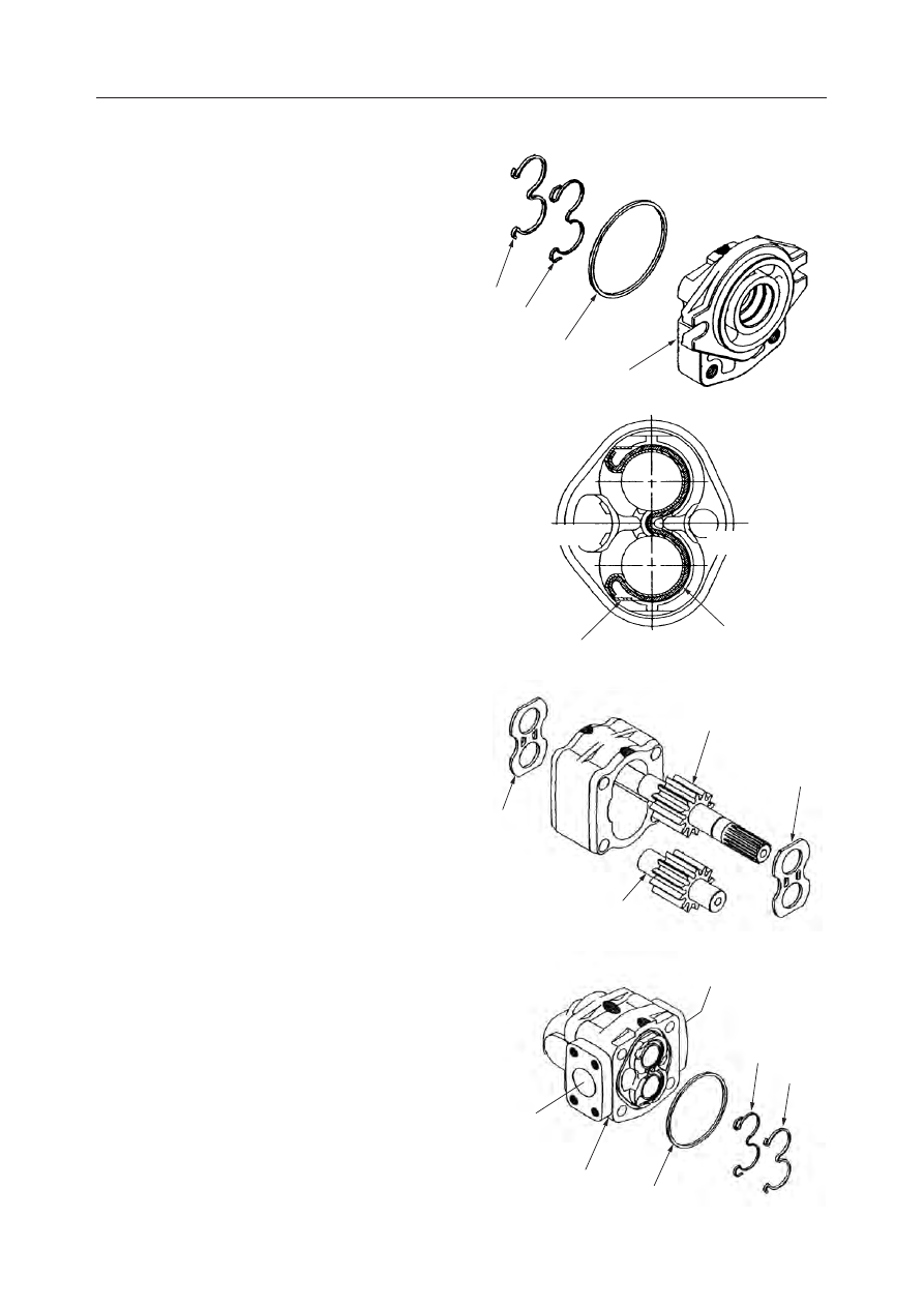
4. Remove the gasket (2) from the flange (1).

5. Remove the backup ring (5) and gasket (6) from

the flange (1).

6. Remove the bushing (7), the bushing (8), the

drive gear (9), and the driven gear (10) from the
housing.
• Be careful to keep the bushings separated and

in their original places.

• Be careful not to scratch or otherwise damage

the inside of the housing.

7. Remove the gasket (2) from the adapter plate

(11).

8. Remove the backup ring (5) and gasket (6) from

the adapter plate (11).

L4D153

1

2

6

5

L4D152E

6

5

SUCTION SIDE

DISCHARGE SIDE

L4D154

9

10

8

7

L4D155E

6

2

11

5

SUCTION SIDE

DISCHARGE SIDE

HYDRAULIC UNITS

HYDRAULIC PUMP

IV-20

TB175W

9. Remove the rear cover (17).

10. Remove the gasket (12) from the adapter plate

(11).

11. Remove the bushing (13), bushing (14), the drive

gear (15), and the driven gear (16).
• Be careful to keep the bushings separated and

in their original places.

• Be careful not to scratch or otherwise damage

the inside of the rear cover.

12. Remove the gasket (18), (19) from the bushing

(13) and the bushing (14).
• Be careful to keep the bushings separated and

in their original places.

L4D156

12

13

18

19

17

14

15

16

11

HYDRAULIC UNITS

HYDRAULIC PUMP

IV-21

TB175W

INSPECTION AND ADJUSTMENT

Checking Parts

After checking the disassembled parts for dirt or
discoloration, clean them with diesel fuel. However,
do not let diesel fuel get on rubber parts. Check each
part for the following points and if there is any trouble,
repair or replace the part.

Housing

The gear pump is made so that the crests of the gear
teeth make light contact with the housing walls as a
means of increasing its efficiency. Therefore, contact
marks can be seen near the suction port in any pump
that has been operated.
It is normal if the depth of the contact marks is within
0.1 mm. If the depth exceeds the use limit in the above
figure, replace the pump assembly.

Bushing

The ideal situation is for the sliding surfaces to have
no roughness and for the suction side half to be
lustrous. Also, it is satisfactory if strong contact
marks can be seen on the side surface on the suction
side and minute contact marks can be seen on the
discharge side.
• Contact marks can be seen on the sliding surface of

the entire bearing inner diameter and it is so rough
that it looks like it has been clawed.

• There is a large number of scratches around the

circumference of the side surface and it is so rough
that it looks like it has been clawed.

• There are marks from foreign matter biting into the

sliding surface of the bearing inner diameter and
the side surface.

Dirty hydraulic oil is one likely cause of such wear. In
such a case, replace the hydraulic oil and flush out
affected hydraulic circuit completely.

DISCHARGE SIDE

SUCTION SIDE

CONTACT MARKS

T7D157E

T7D158E

A

SUCTION SIDE

DISCHARGE SIDE

CONTACT MARKS

DEPTH OF CONTACT MARKS:
A    0.15mm

HYDRAULIC UNITS

HYDRAULIC PUMP

IV-22

TB175W

Other likely causes are as follows.

• Excessive load due to damage to the relief valve.
• Cavitaion or aeration.
• Hydraulic oil temperature is too high.
• Hydraulic oil is deteriorated.
• Hydraulic oil’s viscosity is low.
If it is necessary to replace the bushings, this means
that the gear shaft and gear side surfaces are also
rough or worn severely, so replace the gears at the
same time as the bushings are replaced.

Gear

Replace a gear if it is in the following condition.
1. The shaft or the gear side surfaces ar so rough that

they look like they have been clawed.

2. There are cracks in the tooth roots and there is

extreme abnormal wear in the tooth surfaces.

3. None of the points coming into contact with the

oil seal should be abraded to a depth in excess of
0.1 mm.

Seals

• Check oil seals for scratches in the seal surface,

wear, deformation or deterioration of the rubber’s
elasticity. If a seal is abnormal, replace it.

• Replace seals when the hydraulic pump is disas-

sembled.

• Check the backup ring for scaling and cutting. If it

is abnormal, replace it.

Test Operation

The best method for testing the pump’s operation is to
mount it in a test stand. However, if that cannot be
done, test it under the conditions it would be subjected
to if it were installed in the machine.
Also, if any abnormal wear is discovered during
disassembly, be sure to replace the hydraulic oil and
return filter.
1. Install a pressure gauge in the high pressure

piping near the pump.

2. Run the engine at 500~1,000 rpm and set the

control valve in the neutral position.

3. Run the pump for 10 minutes under the conditions

in (2), then increase the engine’s speed to
1,500~2,000 rpm and run it for another 10 min-
utes.

4. Next, run the pump so that it reaches the rated

pressure (

 “II. Specifications, Specification

Tables”) for 5 minutes at a time for each addi-
tional 1.96~2.94 kPa of pressure.

Afterward, after operating each ciruit for about 5
minutes, replace the return filter or clean it.
In addition, during the process of raising the pressure,
pay careful attention to the oil temperature, the pump’s
surface temperature and the operating noise. If the oil
temperature or the pump’s surface temperature be-
come abnormally high, eliminate the load from the
pump and let the temperature drop before resuming
the test.

HYDRAULIC UNITS

HYDRAULIC PUMP

IV-23

TB175W

Measuring the Discharge Volume

After completing the test operation, measure the
discharge volume.
1. Connect a tester (1) to the discharge side of the

pump (2).
• There should be no mistakes made in the

tester’s pipe installation.

2. Open the tester’s loading valve and start the

engine.

3. Run the engine at the rated speed.
4. Gradually close the loading valve and apply the

rated pressure to the pump (2).

5. Measure the discharge volume and the pump’s

speed (engine speed).

HYDRAULIC UNITS

HYDRAULIC PUMP

IV-24

TB175W

TROUBLESHOOTING

Symptom

Probable Causes

Remedy

Pump won’t discharge.

• Direction of rotation is reversed.

• Oil level in the tank is low.
• Suction side pipe or suction filter is

clogged.

• Hydraulic oil’s viscosity is too high.

• Speed is low.

• Run the pump in the specified direc-

tion.

• Replenish the oil to the specified level.
• Clean the pipes.

• Replace the hydraulic oil with oil of the

proper viscosity.

• Run the pump at the specified speed.

Noise level is high.
Abnormal noise is
generated.

• Suction side hose is crushed, the suc-

tion filter is clogged or cavitation is
occurring.

• Suction side joint is loose and air is

being sucked in.

• Hydraulic oil’s viscosity is too high,

and cavitation is occurring.

• Pump and engine are out of center with

respect to each other.

• There are bubbles in the hydraulic oil.

• Remove the dirt or eliminate the crushed

condition of the hose.

• Tighten all the joint.

• Replace the hydraulic oil with oil of the

proper viscosity.

• Correct the centering  between the pump

and engine.

• Investigate the cause of the bubbles

and correct it.

Oil  leaks  from  oil  seals.

• Oil seal is worn, damaged or deformed. • Replace  the  oil  seal.

Oil leaks from mating sur-
faces between housing and
flange and between hous-
ing and cover.

• Body seal is damaged or worn by rub-

bing.

• Replace with a new part.

Discharge volume is low.

• Bushing seal is damaged.
• Cavitation is occurring.

• Aeration is occurring.

• Viscosity of the hydraulic oil is too

low.

• Replace the bushing.
• Clean the suction filter and suction side

piping.

• Check for insufficient tightening of

pipes, etc. and repair.

• Replace the hydraulic oil with oil of the

proper viscosity.

HYDRAULIC UNITS

CONTROL VALVE

IV-25

TB175W

CONTROL VALVE (MONO-BLOCK)

CONSTRUCTION

  1. Right Travel Section
  2. Bucket Section
  3. Boom [1] Section
  4. Arm [2] Section
  5. Left Travel Section
  6. Auxiliary Section
  7. Boom [2] Section
  8. Arm [1] Section
  9. Swing Section

W2D200E

A

A

B

C

B

D

E

F

G

H

K
J

C

Z

E

D

F

G

H

K

J

VIEW  Z

1 2

4 3

5

6

8

9

7

HYDRAULIC UNITS

CONTROL VALVE

IV-30

TB175W

  1. Plug
  2. O-ring
  3. Poppet
  4. Spring
  5. Plug
  6. Main Relief Valve

W2D205E

6

2

1

3

4
5

SECTION “J-J”

SECTION “K-K”

HYDRAULIC UNITS

CONTROL VALVE

IV-31

TB175W

Main Relief Valve

Port Relief Valve

Anti-Drift Valve

  1. Plug
  2. Sleeve
  3. Main Poppet
  4. Spring
  5. Seat
  6. Needle Valve
  7. Spring
  8. O-ring
  9. Backup Ring
10. O-ring

11. Plug
12. O-ring
13. Nut
14. Piston
15. Plug
16. O-ring
17. Nut
18. O-ring
19. Backup Ring

  1. Housing
  2. Plug
  3. Poppet
  4. Poppet
  5. Piston
  6. Needle Valve
  7. Spring
  8. Spring
  9. Spring

10. Adjusting Screw
11. Washer
12. Nut
13. O-ring
14. O-ring
15. Backup Ring
16. O-ring
17. O-ring
18. Backup Ring

  1. Body
  2. Poppet
  3. Plug
  4. Piston
  5. Spool
  6. Sleeve
  7. Spring
  8. Spring
  9. O-ring
10. O-ring
11. Backup Ring
12. Backup Ring
13. O-ring
14. Plug
15. O-ring
16. Spring Holder

L2D207

5 3

16 7 6

1

8

9 2 1112 10

4 18 17

14 15

13

L2D208

15

15

6

2

8

1

14

3

4

5
7

13

11

10

9

12

16

W2D206

15 17 11 16 14 12 10 7

6

4 3 2

13

1

5 9 8 18 19

HYDRAULIC UNITS

CONTROL VALVE

IV-32

TB175W

OPERATION

This control valve has a structure incorporating a 4-
section and a 5-section part.

When All Spools are in the Neutral Positions
Center bypass passage

The oil supplied from the pump P1 flows through the
center bypass passage (1) and the tank passage (2) of
the 4-section part, and through the ports T1 and T2,
and then back to the tank.
The oil supplied from the pump P2 flows through the
center bypass passage (3) and the passage (4) of the 5-
section part, the tank passage (2) of the 4-section part,
the ports T1 and T2, and then back to the tank.

Signal passage

The oil supplied from the port PP of the signal passage
passes through the filter (5), orifice (6), passage (7),
and flows into the pilot chamber (9) of the straight
travel spool (8). At the same time, the oil from the
signal land of individual spools of the 5-section part
passes through the passage (10), signal lands of indi-
vidual spools of the 4-section part, signal land (11) of
the bucket spool, and then flows into the tank passage

(2).
Concurrently, the oil that passed through the signal
land (12) passes through the signal land (13) and
flows into the tank passage (14).
On the other hand, the oil that passed through the
passage (15) and entered the signal passage of the
travel spool of the 4-section part flows through the
signal land (16) to the tank passage (2).

L3D209

10

P2

T1

5P3

PH

14

12

13

9

8

4

15

7

P1

4P

1

PT

11

16

PP

5

6

T2

2

HYDRAULIC UNITS

CONTROL VALVE

IV-33

TB175W

Independent Operation
Travel spool switching

Switching the spool (1) on the right travel lever closes
the center bypass passage (2), and the oil supplied
from the pump P1 passes through the center bypass
passage (2) and bridge passage (3), and flows into the
port 4A1. The return oil flows from the port 4B1
through the head of the spool (1) and back to the tank
passage (4).
Switching the spool (5) on the left travel lever allows

the oil supplied from the pump P2 to pass through the
parallel passages (6), the head of straight travel spool
(7), the passages (8) and (9), and to flow into the port
5A5. The return oil flows from the port 5B5 to the tank
passage (4). Part of the oil from the pump P2 passes
through the orifice (10), raises the poppet (11), passes
through the passage (3), and flows into the port 5A5.

Bucket spool switching

Switching the spool (1) by pressurizing the port 4Pa2
closes the center bypass passage (2). The oil supplied
from the pump P1 raises the parallel passages (3) and
the load check valve (4). Then the oil flows through
the passage (5) and the head of the spool (1), and
enters the port 4A2. The return oil flows from the port
4B2 through the head of the spool (1), and back to the

tank passage (6). Also, part of the oil is supplied from
the orifice (7) to the left travel section, enabling
concurrent operations of the buckets during right and
left travel operations.

L3D210

7

2

6

8

1

3

2

4

P2

5

9

10

11

5Pb4

4Pb2

5Pa4

4Pa2

4Pa2

5A4

5B4

4A2

4B2

2

3

4

5

7

6

1

L3D211

HYDRAULIC UNITS

CONTROL VALVE

IV-34

TB175W

Boom spool switching

1. When the spool is in the neutral position

The poppet (1) of the anti-drift valve mounted on the
cylinder head of the boom [1] is seated by the pressure
from the port 4B3. This pressure is applied through

the passage (2), spool (3), passage (4), and spring
chamber (5).

2. Raise

Switching the spool (6) of the boom [1] by pressuriz-
ing the port 4Pb3 closes the center bypass passage (7).
The oil supplied from the pump P1 passes through the
parallel passages (8), load check valve (9), passage
(10), and the head of the spool (6). Then the oil raises
the poppet (1) of the anti-drift valve and flows into the
port 4B3.
Concurrently, the spool (12) of the boom [2] is switched
by the passage (11) to close the center bypass valve
(13). The oil supplied from the pump P2 passes
through the parallel passages (14), load check valve
(15), passage (16), the head of the spool (12), and the

passage (17), and then joins into the port 4B3. Part of
the oil through the orifice (18) of the spool (12)
returns to the tank.
The return oil flows from the port 4A3 through the
head of the spool (6) of the boom [1], and back to the
tank passage (19).

L2D212

3

4 2

5

1

L2D213

19

8

10 9

6

1

11

17

7

13

14

15

18

12

16


Content      ..     8      9      10      11     ..