Takeuchi Hydraulic Excavator TB175W (S/N 17540001~). WORKSHOP MANUAL - page 9
 

  Index      Manuals     Takeuchi Hydraulic Excavator TB175W (S/N 17540001~). WORKSHOP MANUAL


Search            copyright infringement  


Content      ..     7      8      9      10     ..


Takeuchi Hydraulic Excavator TB175W (S/N 17540001~). WORKSHOP MANUAL - page 9


HYDRAULIC UNITS

HYDRAULIC PUMP

IV-3

TB175W

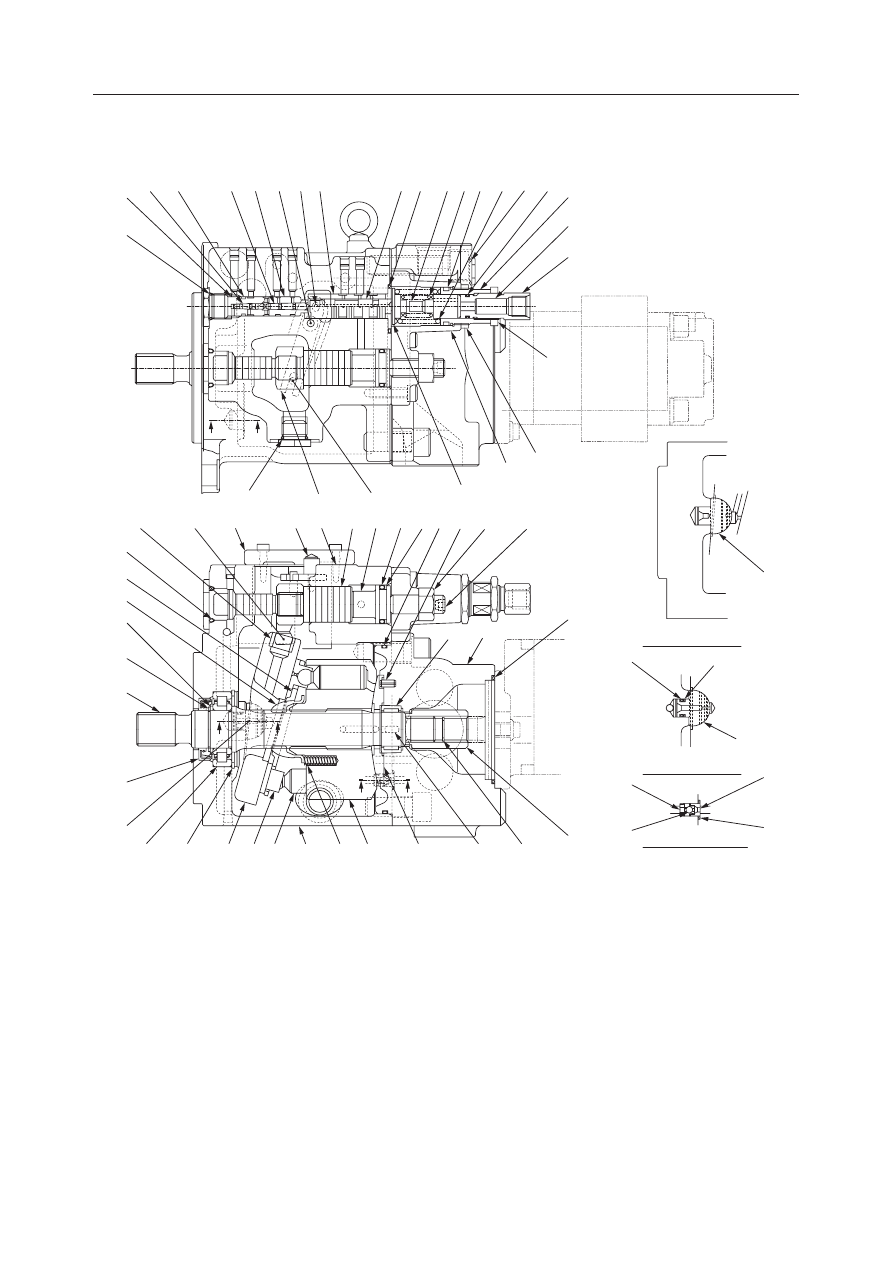
HYDRAULIC PUMP (PISTON)

CONSTRUCTION

  1. Shaft
  2. Coupling
  3. Collar Bearing
  4. Needle Bearing
  5. Spacer
  6. Cylinder Block
  7. Piston
  8. Shoe
  9. Shoe Holder
10. Guide
11. Spring
12. Swash Plate
13. Bushing
14. Pin

15. Pin
16. Housing
17. Cover
18. Cover
19. Valve Plate
20. Pin
21. Piston
22. Stopper
23. Seat
24. Stopper
25. Ball
26. Pin
27. Lever
28. Piston

29. Case
30. Spring Seat
31. Spring
32. Spring
33. Stem
34. Nut
35. Cover
36. Sleeve
37. Spool
38. Pin
39. Pin
40. Piston
41. Pin
42. Case

43. Adjusting Screw
44. Adjusting Screw
45. Piston
46. O-ring
47. O-ring
48. O-ring
49. O-ring
50. O-ring
51. O-ring
52. O-ring
53. O-ring
54. O-ring
55. O-ring
56. O-ring

57. Packing
58. Oil Seal
59. Backup Ring
60. Backup Ring
61. Nut
62. Nut
63. Ring
64. Ring
65. Ring
66. Spring Pin
67. Adjusting Screw

SECTION “V-V”

L3D100E

SECTION “X-X”

SECTION “W-W”

V

V

X

X

W

W

52

42

40

49

28 29 39 38 36

37 46 33 31 54 32

50

51

43

45

61

44

23

51

25

24

59

14

55

56

15

34

35

30

52

27

26

1

58

14

3

64

12

8

7

16

11

6

19

66

65

2

18

63

10

48

5

9

13

20

17

41 57

21 22 53 60 47 66 62

67

4

HYDRAULIC UNITS

HYDRAULIC PUMP

IV-4

TB175W

OPERATION

Piston Pump

This pump is a variable displacement piston pump
with a single cylinder block, which discharges two
equal volumes.
Ten pistons (2) are installed in the cylinder block (1),
and the end surface is in contact with the valve plate
(3). The suction port C and the discharge port A of the
pump P1 and the discharge port B of the pump P2 are
arranged in the valve plate (3). On the other hand, the
swash plate (4) is fastened to the housing at a given
inclination, and the pistons (2) rotate along this swash
plate (4).
When the shaft (5) is rotated, the cylinder block (1)
rotates, the pistons (2) in the cylinder block execute
reciprocating movement along the swash plate (4),
and the pump executes suction and discharge. At this
time, the pistons in contact with the discharge port A
of the valve plate (3) operate as the pump P1, while the
pistons in contact with the discharge port B operate as
the pump P2.
In this way, the ten pistons (2) execute one suction and
discharge stroke with each revolution of the cylinder
block (1), so that suction and discharge are executed
continuously when the shaft (5) is rotated continu-
ously.
As the piston stroke displacement depends on the
inclination of the swash plate (4), the discharge flow
quantity can be changed by changing the inclination
of the awash plate (4).

Discharge volume control

The lever (1) can pivot on the pin and is linked with
the sleeve (2) and pin (3). The pin (3) is linked with the
swash plate (4) to change the inclination of the swash
plate.
The force exerted by the springs (7) and (8) acts on the
spool (6) while the average discharge pressure from
pumps P1 and P2 and discharge pressure from pump
P3 act on the piston (9). Also, the discharge pressure
selected by the shuttle valve (11) and transmitted
through the sleeve (2) and spool (6) acts on the servo
piston (10).

L3D101

3

1

2

4

5

L3D103

11

8

7

2

9

3

10

4

1

6

P2

P1

P3

HYDRAULIC UNITS

HYDRAULIC PUMP

IV-5

TB175W

When the discharge pressure from pump P1 or P2
exceeds the setting value, the average pressure of the
discharges from pumps P1 and P2, (P1 + P2)/2, acts
on the piston (9). Then, the spool (6) is pushed and
moved to the right until this operating pressure bal-
ances the force exerted by the springs (7) and (8).
When the spool (6) moves, the hydraulic oil passes
through the sleeve (2), spool (6), and hydraulic pas-
sage (11), and is supplied to the large bore of the servo
piston (10). This pushes the servo piston (10) to the
left, decreasing the inclination of the swash plate (4).
The movement of the servo piston (10) is conveyed
via the piston (3) to the lever (1). The lever (1) pivots
on the pin fixed on the housing and moves the sleeve
(2) to the right. The sleeve (2) continues to move until
the hydraulic oil passage (11) connected to the large
bore is closed.

When the discharge pressure from pumps P1 and P2
is reduced, the spool (6) is pushed back to the left by
the force exerted by the springs (7) and (8), and the
hydraulic oil passage (11) connected to the large bore
is connected to the tank passage. Then the servo
piston (10) moves to the right by pressure from the
small bore on its own, increasing the inclination of the
swash plate (4). The lever (1) pivots on the pin and
moves the sleeve (2) to the left. This operation contin-
ues until the openings of the sleeve (2) and spool (6)
are closed.

Thus, by changing the inclination of the swash plate
(4) the discharge is controlled and only minimum
pressure and flow required for the load are supplied
from the pump. This minimizes the pressure loss of
the pump. The inclination of the swash plate (4) varies
depending on the operating pressures not only by the
pumps P1 and P2 but also by the pump P3. Thus, the
P-Q curve for the piston pumps shows that the engine's
power is fully utilized (full horse power control).

L3D124E

L3D104

P2
P1

9

2

7 8

3

4

1

10 11

6

L3D105

P2
P1

2

7 8

3

4

1

10 11

6

HYDRAULIC UNITS

HYDRAULIC PUMP

IV-6

TB175W

DISASSEMBLY AND ASSEMBLY

General Cautions

• Carry out disassembly and assembly operations in

a clean place and provide clean containers to place
the disassembled parts in.

• Before disassembly, clean around the ports and

remove the paint from each joint using a wire
brush.

• Clean all disassembled parts in cleaning solvent.

Use a lint free cloth, or air dry the parts.

• Make match marks on each part so that they will be

assembled in the same positions when assembled.

• Replace all seals with new ones each time the

hydraulic units is disassembled.

• Check each part to make sure there is no abnormal

wear or seizing and use sandpaper, etc. to remove
any burrs, sharp edges, etc.

• Do not turn adjusting screws if not required.
• Apply hydraulic oil to sliding surfaces and apply a

thin coating of grease to seals when assembling
them.

Disassembly

1. Loosen the drain plug (1) and drain out the oil.

2. Remove the cap screws and remove the gear

pump.

3. Remove the coupling.

4. Remove the cap screws and remove the cover.

• Remove the cover in horizontal condition.

L3D106

1

L3D107

L3D108

HYDRAULIC UNITS

HYDRAULIC PUMP

IV-7

TB175W

5. Remove the valve plate.

6. Disassemble the cylinder block.

a. Remove the cylinder block from the shaft.

b. Remove the guide (3), the springs (4), the

holder (5), and the pistons (6) from the cylinder
block (7).
• Disassemble the inside of the cylinder block

(7) only when required.

7. Remove the swash plate.

8. Remove the pin R and pin L.

L3D109

L3D110

L3D111

3

5

7

6

4

L3D112

HYDRAULIC UNITS

HYDRAULIC PUMP

IV-8

TB175W

9. Remove the shaft while tapping its rear end with

a plastic hammer.

10. Remove the cap screws and remove the cover.

11. Remove the two springs [inside, outside].

12. Remove the spring seat.

13. Remove the cap screws and remove the cover.

14. Remove the lever.

15. Remove the sleeve, the spool and piston.

L3D113

L3D114

L3D115

L3D116

HYDRAULIC UNITS

HYDRAULIC PUMP

IV-9

TB175W

16. Remove the plug and the pin.

17. Remove the piston.

• Screw the bolt into the screw hole (M4) at the

end face of the piston, and grab the bolt to pull
out the piston.

18. Loosen the lock nut (3) and remove the adjusting

screw (2).
• Record the length of the adjusting screw pro-

trusion before starting the disassembly.

L3D117

L3D118

L3D119

3

2

HYDRAULIC UNITS

HYDRAULIC PUMP

IV-10

TB175W

Assembly

1. Install the adjusting screw (2).

• Fix the adjusting screw (2) to the same length

as previously assembled using the lock nut (3).

Lock nut: 98 N·m

2. Install the piston.

3. Install the drain plug (1).

4. Install the oil seal.

5. Install the shaft in the housing.

• Tap the spline end with a plastic hammer to

positively install the outer race of the bearing
in the housing hole.

L3D119

3

2

L3D118

L3D106

1

L3D120

HYDRAULIC UNITS

HYDRAULIC PUMP

IV-11

TB175W

6. Fit the pin R and L on the swash plate.

7. Install the swash plate in the housing.

• Insert the bushing into the swash plate.
• Apply grease on the sliding surfaces of the

swash plate, pin R and pin L.

8. Mount the pin and tighten the plug.

Plug: 29.4 N·m

9. Mount the piston in the housing.

L3D121

L3D122

L3D117

L3D123

HYDRAULIC UNITS

HYDRAULIC PUMP

IV-12

TB175W

10. Mount the sleeve and spool.

11. Install the lever on the housing.

12. Install the cover and install the cap screws.

Cap screw: 29.4 N·m

13. Install the spring seat.

• Apply grease to the spherical part of the spring

seat.

14. Install the two springs [inside, outside].

15. Assemble the cylinder block.

a. Install the springs in the cylinder block.
b. Install the guide (3) in the cylinder block.

• Apply grease to the spherical part of the

guide.

c. Attach the pistons (6) to the shoe holder (5),

and install the shoe holder (5) in the cylinder
block.

L3D116

L3D115

L3D114

L3D111

3

5

7

6

4

HYDRAULIC UNITS

HYDRAULIC PUMP

IV-13

TB175W

16. Install the cylinder block matching the spline of

the shaft.
• Apply grease to the sliding surfaces of the

piston shoes and the plate.

17. Apply grease to the rear of the valve plate and

install it to the cover, matching the knock hole.

18. Install a large and a small O-ring in the cover.

19. Install the cover and install the cap screws.

• Install the cover parallel to the housing instal-

lation surface.

Cap screw: 235 N·m

20. Install the coupling on the end of the main pump

shaft.

21. Unite the main pump and gear pump and fix them

with the cap screws.

Cap screw: 56.9 N·m

L3D110

L3D108

L3D107

HYDRAULIC UNITS

HYDRAULIC PUMP

IV-14

TB175W

Parts

Judgment Criteria

Treatment

• A clearance S of 0.05 mm or more

between the piston and the cylinder
block

• Occurrence of scratches, scoring,

abnormal wear, etc. on sliding parts

Piston and cylinder
block assembly

Slack of the piston
shoe

Shaft and oil seal
installation part

Valve plate

• A slack S of 0.2 mm or more for the

piston shoe

• A wear amount of 0.025 mm at the

installation part of shaft and oil seal

• No abnormal scratches (0.02 mm or

more), wear, or sticking for the slid-
ing surfaces

• Exchange

• Exchange.

• Exchange

• Exchange

• Correct by lapping

or exchange.

• No abnormal wear or harmful

scratches of the sliding surfaces

• At the time of reassembly after dis-

assembly

• No abnormal scratches, wear, or

flaking of the tooth surfaces

• No abnormal scratches, wear, or

flaking of the rolling surfaces

• Exchange

• Exchange

• Exchange

• Exchange the shaft

and the assembly.

Bushing

Seals and O-rings

Drive gear and
driven gear

Ball bearings and
needle bearings

OIL SEAL MOUNT

STANDARD DIMENSION

INSPECTION AND ADJUSTMENT

Checking the Parts

HYDRAULIC UNITS

HYDRAULIC PUMP

IV-15

TB175W

TROUBLESHOOTING

Symptom

Probable Causes

Remedy

• Remove the dirt or eliminate the pinched

condition of the hose.

• Retighten each joint.

• Replace the hydraulic oil with oil of the

proper viscosity.

• Center the pump with respect to the

engine.

• Investigate the cause of the bubbles and

repair it.

• Operate the engine at the specified speed.

• Check and replace the drain piping.

• Replace the damaged parts or replace

the pump.

Noise is loud. Abnormal
noise is generated.

• The suction hose is pinched or the suc-

tion filter is clogged.

• The suction side joint is loose and air is

being sucked in.

• The hydraulic oil’s viscosity is too high

and cavitation is occurring.

• The pump is off center with respect to

the engine.

• There are bubbles in the hydraulic oil.

• The engine’s speed is higher than the

specified speed.

• The drain back pressure is higher than

the specified pressure.

• The bearing, etc. is mechanically dam-

aged.

• The engine’s speed is too low.
• The oil temperature is abnormally high.

• The hydraulic oil’s viscosity is too high.

• The pump’s volumetric efficiency has

dropped.

• The horsepower setting adjustment

screw is loose.

• The oil level in the tank is low.

• The suction side pipe or the suction

filter is clogged.

• The amount of leakage from hydraulic

devices other than the pump is increasing.

• Operate the engine at the specified speed.
• Stop the machine and let the oil cool off,

then check again.

• Replace the hydraulic oil with oil of the

proper viscosity.

• Replace the pump.

• Reset the screw and lock it.

• Replenish the tank with hydraulic oil to

the specified level.

• Clean the piping.

• Repair the hydraulic device or replace

it.

• The relief valve setting has dropped.
• The amount of leakage from hydraulic

devices other than the pump is increasing.

• The pump’s volumetric efficiency has

dropped.

• The peak pressure is generated due to a

drop in the relief valve’s response.

• There is foreign matter trapped in the

pilot line or foreign matter is caught in
the sliding parts of the control equip-
ment.

• Leakage from the pump is increasing.
• The bearings, etc. are mechanically dam-

aged.

• There is seizing of sliding parts.

• Seals are damaged.
• The shaft surface which slides against

the oil seal is worn.

• The plug or bolts are loose.

• Reset the relief valve setting.
• Repair the hydraulic device or replace

it.

• Replace the pump.

• Repair the relief valve or replace it.

• Remove the foreign matter and repair or

replace the scratched parts.

• Replace the pump.
• Replace the damaged parts or replace

the pump.

• Replace the damaged parts or replace

the pump.

• Replace the seals.
• Replace the shaft or replace the pump.

• Tighten them or replace the seals.

Discharge is insufficient.

Pressure doesn’t rise.

The rotational speed drops
when there is a dynamic
load.

Abnormal heat is gener-
ated.

Hydraulic oil is leaking.

HYDRAULIC UNITS

HYDRAULIC PUMP

IV-16

TB175W

HYDRAULIC UNITS

HYDRAULIC PUMP

IV-17

TB175W

HYDRAULIC PUMP (GEAR)

CONSTRUCTION

  1. Flange
  2. Housing
  3. Drive Gear
  4. Driven Gear
  5. Bushing

  6. Adapter Plate
  7. Rear Cover
  8. Drive Gear
  9. Driven Gear
10. Bushing

11. Bushing
12. Bushing
13. Gasket
14. Gasket
15. Buckup Ring

16. Gasket
17. Gasket
18. Oil Seal
19. Snap Ring

Gear Pump

The gear pump consists of a single gear case, inside of
which is a drive gear (1) and a driven gear (2) engaged
with each other. By turning the drive shaft (3), the
space between the case and the gears is filled with oil.
This oil is thus sent through the pump from the inlet
to the outlet.

19

3

18

14

1

15

4

5

11

13

10

9

17

8

7

16

6

2

12

L4D150

INLET

OUTLET

Y1-D101E

HYDRAULIC UNITS

HYDRAULIC PUMP

IV-18

TB175W

DISASSEMBLY AND ASSEMBLY

General Cautions

• Carry out disassembly and assembly operations in

a clean place and provide clean containers to place
the disassembled parts in.

• Before disassembly, clean around the ports and

remove the paint from each joint using a wire
brush.

• Clean each of the disassembled parts with a clean-

ing oil such as diesel fuel.

• Make match marks on each part so that they will be

assembled in the same positions when assembled.

• Replace all seals with new ones each time the pump

is disassembled, coating them lightly with grease.

• Check each part to make sure there is no abnormal

wear or seizing and use sandpaper, etc. to remove
any burrs, sharp edges, etc.

• Adjust adjustment screws only when required.

Following is an explanation of the gear pump disas-
sembly procedure.
Follow the procedure used to disassemble the gear
pump in reverse order when reassembling it.

1. Remove the cap screws.

Screw: 98~108 N·m

2. Remove the flange (1).

3. Remove the snap ring (3) and the oil seal (4) from

the flange (1).
• Be careful not to scratch or otherwise damage

the flange.

• When re-assembling, install the oil seal using

the jigs A and B.

L4D151

4

3

1

T7D152

B

A

4

1


Content      ..     7      8      9      10     ..