Takeuchi Hydraulic Excavator TB175W (S/N 17540001~). WORKSHOP MANUAL - page 11
 

  Index      Manuals     Takeuchi Hydraulic Excavator TB175W (S/N 17540001~). WORKSHOP MANUAL


Search            copyright infringement  


Content      ..     9      10      11      12     ..


Takeuchi Hydraulic Excavator TB175W (S/N 17540001~). WORKSHOP MANUAL - page 11


HYDRAULIC UNITS

CONTROL VALVE

IV-35

TB175W

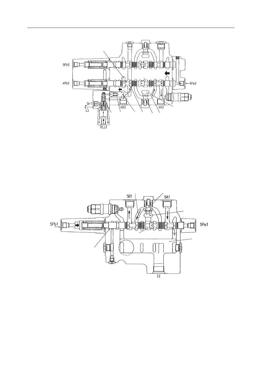
3. Lower

Switching the spool (6) of the boom [1] by pressuriz-
ing the port 4Pa3 closes the center bypass passage (7).
The oil supplied from the pump P1 passes through the
parallel passages (8), load check valve (9), passage
(10), and the head of the spool (6), and then flows into
the port 4A3.

Pressurizing the ports 4Pa3 and PLc1 at the same time
switches the spool (3) of the anti-drift valve. This
reduces the pressure in the spring chamber (5) through
the drain port Dr1 to open the poppet (1). The return
oil flows through the head of the spool (6) of the boom
[1], orifice, notch, and back to the tank passage (20).

Swing spool switching

Switching the spool (1) by pressurizing the port 5Pb1
closes the center bypass passage (2). The oil supplied
from the pump P2 passes through the parallel pas-
sages (3), load check valve (4), passage (5), and the
head of the spool (1), and then flows into the port 5B1.
The return oil flows from the port 5A1 through the
head of the spool (1), and back to the tank passage (6).

L2D214

3

5

1

6

9 10

8

7

20

L2D215

1

2

4

3

6

5

HYDRAULIC UNITS

CONTROL VALVE

IV-36

TB175W

Arm spool switching

1. Dump

Switching the spool (1) of the arm [1] by pressurizing
the port 5Pb2 closes the center bypass passage (2).
The oil supplied from the pump P2 passes through the
center bypass passage (2), tandem check valve (3),
passage (4), and the head of the spool (1), and then
flows into the port 5B2.
Concurrently, part of the oil from the pump P2 flows
through the parallel passages (5), orifice (6), load
check valve (7), and the passage (4), and then enters
the port 5B2.
Switching the spool (1) of the arm [1] causes the spool
(17) of the arm [2] to be switched by the passage (8)

to close the center bypass passage (9). The oil sup-
plied from the pump P1 flows through the center
bypass passage (9), passage (10), and check valve
(11), and joins into the port 5B2. Part of the oil from
the pump P1 also, flows through the tandem check
valve (12), the passages (13) and (4), and the head of
the spool of the arm [1], and then joins into the port
5B2. Part of the oil from the orifice (14) of the spool
flows into the tank.
The return oil flows from the port 5A2 through the
head of the spool (1) of the arm [1], and back to the
tank passage (15).

2. Load

L2D216

17

11

10

14

12

9

2

13

15

5

3

7

1

6

8

4

L2D217

1

18

6

4

7

3

5

2
9

13

16

12

14

10

11

17

HYDRAULIC UNITS

CONTROL VALVE

IV-37

TB175W

Switching the spool (1) of the arm [1] by pressurizing
the port 5Pa2 closes the center bypass passage (2).
The oil supplied from the pump P2 passes through the
center bypass passage (2), tandem check valve (3),
passage (4), and the head of the spool (1) of the arm
[1], and then flows into the port 5A2.
Also, part of the oil from the pump P2 flows through
the parallel passages (5), orifice (6), load check valve
(7), and passage (4), and then enters the port 5A2. The
orifice (6) is provided as a priority throttle for the
concurrent operation with the boom offset operation.
Switching the spool (1) of the arm [1] causes the spool
(17) of the arm [2] to be switched by the passage (16)

to close the center bypass passage (9). The oil sup-
plied from the pump P1 flows through the center
bypass passage (9), passage (10), check valve (11),
passage (4), and the head of the spool (1) of the arm
[1], and then joins into the port 5A2.
The oil from the pump P1 raises the tandem check
valve (12) and from the passage (13) joins into the
port 5A2.
Part of the oil from the orifice (14) of the spool returns
to the tank.
The return oil flows from the port 5B2 through the
orifice and notch of the head of the spool (1) of the arm
[1], and back to the tank passage (18).

Compound Operations during Traveling

When the attachment is operated while traveling, the
passages (1) and (2) are closed, causing the pressure
of the port PP to switch the straight travel spool (3) to
block the flow from the parallel passages (4) of the 5-
section part to the passage (5). This stops the oil
supply from the pump P2 to the left travel spool (6),
and the hydraulic oil from the pump P2 is supplied to
the sections for the attachment. Concurrently, the
hydraulic oil from the pump P1 is separated into two
flows: one flow is from the center bypass (7) of the 4-
section part to the right travel spool (8); and the other
flow raises the poppet (9), passes through the head of
the straight travel spool (3) and passage (5), and
reaches the left travel spool. This keeps the travel
straight.
Part of the oil from the pump P2 flows through the
parallel passages (4), orifice (10), and load check
valve (11), and is supplied to the travel section to
relieve the deceleration shock at the time of switching
of the straight travel spool (3).

L3D216

P1

3

9

5

4

7

1

2

6

8

10

11

4

HYDRAULIC UNITS

CONTROL VALVE

IV-38

TB175W

Anti-Drift Valve

This valve is installed in the boom cylinder head line
to prevent the oil from leaking at the boom cylinder
head line so that the boom will not fall down sponta-
neously when the boom spool is in the neutral posi-
tion.

1. Neutral
The pressure from the cylinder port is applied through
the passage (2), hollow in the spool (3), passage (4),
and to the spring chamber (5). Due to the spring force
and the force produced by the difference in the poppet
areas, the poppet (1) is firmly seated.

2. Raise
The oil supplied from the pump opens the poppet (1)
and flows into the cylinder port.

3. Lower
Switching the spool (3) by pressurizing the port PLc1
causes the oil from the spring chamber (5) to flow
through the passage (4) into the tank port Dr1. This
opens the poppet (1), and the return oil from the
cylinder port 4B3 flows through the spool of the boom
[1] and back to the tank.

L2D219

4

3

2

5

1

L2D220

1

L2D221

3

4

5

1

HYDRAULIC UNITS

CONTROL VALVE

IV-39

TB175W

Main Relief Valve
Relieving Operation

When the pressure in the circuit is low with respect to
the set value, the relief valve is maintained at equilib-
rium. Hydraulic oil from the pump passes through the
orifice from chamber B and arrives at the spring
chamber C and the needle valve (5). On the other
hand, forces F and F1 are acting in the arrow direc-
tions on both sides of the main poppet (6).
F = P 

×

 A

F1 = P 

×

 A1

P: Pressure

A,A1: Sectional Area

Since the sectional area of A is less than that of A1, the
main poppet (6) is pushed by the force “F1-F” to the
seat surface on the left side.

If the pressure in the circuit becomes higher than the
force of the spring (7), the needle valve (5) is pushed
to the right by hydraulic pressure, opening. Oil then
flows around the circumference of the needle valve
(5) and passes through the slits, flowing into the tank
passage (T).

Compared to the chamber B side, the pressure in
chamber C is low and there is no equilibrium in
pressure. For this reason, the main poppet (6) opens
and pressurized oil flows to the tank passage (T).

Pressure Increase Operation

When the pressure is applied to the pilot port PH, the
piston (8) is pushed to the left to hit the plug (9). Then,
the spring force of the spring (7) becomes larger,
increasing the pressure in chamber B.

W2D207

B A

6 C

5

A1

F

F1

W2D208

T

7

5

W2D209

T

B

6 C

W2D210

B

7

8

9

PH

HYDRAULIC UNITS

CONTROL VALVE

IV-40

TB175W

Port Relief Valve
Relieving Operation

When the pressure in the circuit is low with respect to
the set value, the relief valve is maintained at equilib-
rium. Pressure from the pump passes from chamber B
to the orifice in piston (4), then reaches chamber C and
the needle valve (5). On the other hand, forces F and
F1 are acting in the arrow directions on both sides of
the main poppet (6).
F = P 

×

 A

F1 = P 

×

 A1

P: Pressure

A, A1: Sectional Area

Since the sectional area of A is less than that of A1, the
main poppet (6) is pushed by the force “F1-F” to the
seat surface on the left side.

If the pressure in the circuit becomes higher than the
force of the spring (7), the needle valve (5) is pushed
to the right by hydraulic pressure, opening. Oil then
flows around the circumference of the needle valve
(5) and passes through the slits, flowing into the tank
passage (T).

When the needle valve (5) opens, the pressure drops
on the back side of the piston (4), pushing the piston
(4) to be pushed to the right, seating with the needle
valve (5). This shuts off the flow of hydraulic oil to the
rear of the main poppet (6). As a result, the pressure
in chamber C on the inside drops.

Compared to the chamber B side, the pressure in
chamber C is low and there is no equilibrium in
pressure. For this reason, the main poppet (6) opens
and pressurized oil flows to the tank passage (T).

HYDRAULIC UNITS

CONTROL VALVE

IV-41

TB175W

Suction Operation

When the cylinder is operated at high speed, and the
supply of oil cannot keep up with it, creating a vacuum
in chamber B, oil is supplied from the tank side,
preventing the occurrence of cavitation.
When the pressure in chamber B is lower than the
pressure in the tank passage (T), the differences in the
sectional areas A and A1 cause the main poppet (6) to
open. Thus, sufficient oil from the tank passage (T)
enters chamber B, filling the empty space.

HYDRAULIC UNITS

CONTROL VALVE

IV-42

TB175W

DISASSEMBLY AND ASSEMBLY

General Cautions

• Since all parts in control valves are precision

machined, carry out disassembly and assembly
operations in a clean place.

• Before disassembly, clean the outside surfaces

around the valves.

• Clean all disassembled parts in cleaning solvent.

Use a lint free cloth, or air dry the parts.

• Apply hydraulic oil to sliding surfaces and apply a

thin coating of grease to seals when assembling
them.

• Replace all seals with new ones each time the

valves are disassembled.

• Spools and section bodies are specially selected for

a precise fit. Therefore, if any damage is found in
either of these parts, replace the section assembly
as a unit.

• Be sure to number each section and spool to avoid

mistakes during assembly.

• Do not turn adjusting screws if not required.

Following is an explanation of the control valve
disassembly procedure.
Follow the procedure used to disassemble the control
valve in reverse order when reassembling it.
• Before disassembly, number each section and spool.

Disassembly

1. Remove the main relief valve (2), then remove

the O-ring from the valve.

Valve: 49~54 N·m

2. Remove the port relief valve (3), then remove the

O-ring from the valve.
• Do not disassemble the port relief valve, as the

pressure cannot be adjusted after it is reas-
sembled.

• Install the valve in the same position as it was

in before disassembly.

Valve: 59~69 N·m

3. Remove the plug (4), then remove spring (5) and

spool (6). Next, remove the O-ring from the plug.

Plug: 78~88 N·m

W2D211

2

3

3

W2D212

6

5

4

4

HYDRAULIC UNITS

CONTROL VALVE

IV-43

TB175W

L3D226

7

8

9

10

11

12

1

9 8

7

L3D227

15

14

13

15

14

13

L3D228

20

19

1817

16

4. Disassemble the arm [1] and [2] and load check

valve.
a. Remove the plug (7), then remove the O-ring

from the plug.

Plug: 167~196 N·m

b. Remove the spring (8) and poppet (9).
c. <Arm [1]> Remove the sleeve (10), spring

(11) and poppet (12).
<Arm [2]> Remove the sleeve (1).

5. Disassemble the booms [1] and [2], auxiliary,

bucket, offset and the load check valves at the
three common check valves.
a. Remove the plug (13), then remove the O-ring

from the plug.

Plug: 88~98 N·m

b. Remove the spring (14) and poppet (15).

6. Disassemble the left travel load check valve.

a. Remove the plug (16), then remove the O-ring

from the plug.

Plug: 167~196 N·m

b. Remove the sleeve (17), spring (18) and pop-

pet (19).

7. Disassemble the right travel plug (20). Next,

remove the O-ring from the plug.

Plug: 105.9~141.2 N·m

8. Remove the cap screws, then remove cover (21).

Next, remove the O-ring from the cover.

Cap screw: 8.8~10.8 N·m

L3D229

21

HYDRAULIC UNITS

CONTROL VALVE

IV-44

TB175W

L2D232

27

28

29

28

L3D230

L3D231

23

9. Remove the individual spool assemblies from the

valve housing.
• Pull out the spool straight so that the spool

surface will not be damaged.

10. Remove the cap screws, then remove cover (23).

Next, remove the O-ring from the cover.

Cap screw: 8.8~10.8 N·m

11. Disassemble the spool.

• Hold the spool with two pieces of wood so that

the spool will not be damaged.

• Locktite is applied to the thread, so heat the

section around the thread to approximately
200

°

C.

a. Remove the screw (27), then remove the spools.

Cap screw: 19~22 N·m

b. Remove the spring holder (28), spring (29) and

spring holder (28).

12. Pull out the plug (33) and remove the spring (34)

and poppet (35). Then remove the O-ring and
backup ring from the plug (33).
• Screw the bolt into the screw hole (M6 

×

 1.0)

at the end face of the plug, and grab the bolt to
pull out the plug.

L3D236

35

34

33

35
34

33

HYDRAULIC UNITS

CONTROL VALVE

IV-45

TB175W

Anti-Drift Valve

1. Remove the plug (1), then remove the O-ring

from the plug.

Plug: 69~78 N·m

2. Remove the piston (2), spool (3) and spring (4).

3. Remove the plug (5), then remove the O-ring

from the plug.

Plug: 69~78 N·m

4. Remove the sleeve (6). Then remove the O-rings

(8) and (9), and the backup rings (10) and (11)
from the sleeve (6).
• When reassembling, be sure to put the O-rings

and the backup rings in place. Otherwise the
boom can fall spontaneously.

5. Remove the poppet (7), spring seat (12), and

spring (13).
• When reassembling, be sure to apply grease to

the edge of the poppet (7) to prevent the spring
seat and the spring from being displaced.

6. Remove the cap screws, then remove the body

(14) from the housing.

Cap screw: 8.8~10.8 N·m

7. Remove the O-ring from the body (14).

8. Remove the spacer (15).

• Screw the bolt into the screw hole (M4 

×

 0.7)

at the end face of the spacer, and grab the bolt
to pull out the spacer.

9. Remove the O-ring (16) and backup ring (17)

from the spacer (15).

10. Remove the spring (18) and poppet (19) from the

body (14).

L2D237

1

2

3

4

L2D238

5

6

10 8

9

11 7

12

13

L2D239

14

L2D240

15

17
16

18

19

HYDRAULIC UNITS

CONTROL VALVE

IV-46

TB175W

Main Relief Valve

1. Remove the sleeve (2), spring (3) and main pop-

pet (4) from the plug assembly (1).
• The pilot seat (5) is caulked by the tip of the

plug and cannot be disassembled.

2. Remove the O-ring (6) and backup ring (7) from

the pilot seat (5).

3. Remove the O-ring (8) and backup rings (9) from

the main poppet (4).

4. Loosen the lock nut (10) and remove the plug (11)

and piston (12).
• When assembling, after installing the plug,

first partially tighten the lock nut, then fully
tighten it after adjusting the pressure.

5. Remove the O-ring (13) from the plug (11).

6. Loosen the lock nut (14) and remove the plug

(15).

7. Remove the O-ring (16) from the plug (15).

8. Remove the spring (17) and needle valve (18).

W2D213

1

2

3

4

5

6

7

8

9

W2D214

11

12

13

14

15

16

17

18

10

HYDRAULIC UNITS

CONTROL VALVE

IV-47

TB175W

INSPECTION AND ADJUSTMENT

Checking the Parts

Adjusting the Main Relief Valve Pressure

“II. Specifications, Standards for Judging Per-
formance”

Parts

Judgment Criteria

Treatment

• Replace

• Replace

• Replace

• Replace

• Replace

Housing

• Scratches, rust, corrosion of the portion which slides

against the spool.

• Scratches, rust, corrosion of the seal pocket portion of

the part that enters the spool.

• Scratches, rust, corrosion of the port seal portion which

is in contact with the O-ring.

• Scratches, rust, corrosion of the seal portion of the relief

valve, etc.

• Other damage which could be a hindrance to correct

function.

• Scratch marks like being clawed around the outer cir-

cumference sliding portion.

• Scratches on the portion that slides against the seals on

both ends.

• Spool not operating smoothly.

• Imperfect sealing due to damage to the valve or spring.
• Does not catch, but operates lightly when inserted in the

section body and operated.

• Rust, corrosion, deformation, breakage or other marked

damage to the spring, holder or cover.

• Oil leaking to the outside.
• Rust, corrosion or deformation of the seal holder.

• External rust, damage.
• Damage to valve seat contact surface.
• Damage to poppet contact surface.
• Abnormality in the spring.
• O-rings, backup rings, seals

• Replace

• Replace

• Repair or replace.

• Repair or replace.
• Normal

• Replace

• Repair or replace.

• Replace
• Replace
• Replace
• Replace
• As a rule, all these

should be replaced.

Spool

Load Check Valve

Around Springs

Around Spool Seal

Main Relief Valve,
Port Relief Valve,
Anti-Drift Valve

HYDRAULIC UNITS

CONTROL VALVE

IV-48

TB175W

TROUBLESHOOTING

The following items are a list of all the problems that
might occur individually, but in actual practice, 2 or
3 of these problems might occur simultaneously to

compound the trouble. It is therefore desirable to
proceed so that the causes can be eliminated one at a
time.

Symptom

Probable Causes

Remedy

• Replace with a new part.

• Repair or replace the spool.

• Return to the correct shape and check

for eccentric wear of the seal lip.

• Remove paint with paint thinner or re-

move it mechanically. However, at this
time, be careful not to damage the spool
surface or the seal lip.

• Eliminate the factors causing excessive

flow resistance.

Oil leaks from spool seal. • Seal is scratched or the seal lip is worn

due to long use.

• Spool’s seal sliding portion was dam-

aged by some external cause (bruise,
scratch, etc.).

• Seal bulged out and the cover was in-

stalled in a warped state.

• Paint adhered to the sliding portion of

the spool’s seal portion during painting.

• Tank circuit’s pressure became high

and exceeded the pressure level that the
seal was capable of withstanding.

• Foreign matter is biting into the spool’s

sliding surface.

• Oil film between the spool and body

disappears due to abnormally high oil
temperature.

• Lubrication is improper due to deterio-

rating oil.

• Spool is worn from long use or due to

pressure bearing on one side only.

• Spool is bent from externally applied

pressure.

• Entire valve is strained due to strain in

the installation face.

• Valve was used at a pressure or a flow

volume which was out of specification.

• Bolts used to assemble the valve were

tightened excessively.

• Oil is accumulating in the cover (the

side with a spring or a detent) opposite
the side where the spool operates.

• Overhaul and repair or replace.

• Use some method to lower the oil tem-

perature or if the relief valve is operat-
ing frequently, investigate the cause
and reduce the frequency.

• This could be alleviated by simply re-

placing the hydraulic oil, or it could
require an overhaul of the circuit.

• Check the spool’s diameter and con-

sider the necessity of replacement.

• Check the spool’s straightness and other

factors, then repair or replace.

• Loosen the installation bolts, then cut

the installation face and edge and check.

• In the case of pressure, check with a

pressure gauge. In the case of flow
volume, check by the actuator’s speed
of movement and the capacity.

• Check if the assembly bolts are tight-

ened to the specified torque. If the torque
deviates markedly from the specified
torque, tighten them again.

• The spool is leaking oil, so when the

spool moves, oil leaks from the cover.
After confirming this, replace the seal.

• Foreign matter is biting into the load

check valve seat or large scratches were
made by foreign matter biting into the
valve's seat previously.

• Disassemble and check, then overhaul

or replace.

Spool’s sliding is not
smooth.

Cylinder drops while
shifting to a lift operation.

HYDRAULIC UNITS

CONTROL VALVE

IV-49

TB175W

• Check if it isn't just the cylinder’s natu-

ral drop when the cylinder is held. If the
problem is in the cylinder, disassemble
and repair it.

• Replace the spool or replace the valve

block assembly.

• Manually Operated :

Check if there is something interfering
with the link mechanism.
Pilot Operated:
Check the pilot pressure.

• Disassemble and check, then overhaul

or replace.

Symptom

Can’t be held in the spool
neutral position (cylinder
drops).

• Could be mistaken for a great amount of

leakage in the cylinder.

• The gap between the spool and body is

large, so the amount of oil leaking from
the spool is great.

• Spool won’t return completely to the

neutral position.

• Foreign matter is biting into the port

relief valve seat or the anti-cavitation
valve seat and oil is bypassing. Or a seat
is damaged.

Probable Causes

Remedy

• Foreign matter is biting into the relief

valve seat and oil is bypassing. Or the
seat is damaged.

• The relief valve’s adjustment screw is

loose.

• Foreign matter is biting into the port

relief valve seat or the anti-drift valve
seat and oil is bypassing. Or a seat is
damaged.

• Spool stroke is not the specified stroke.

• Pump is damaged and no oil is dis-

charged.

• Disassemble and check, then overhaul

or replace.

• Try tightening the adjustment screw. If

it is loose, correct the setting and tighten
the lock nut securely.

• Disassemble and check, then overhaul

or replace.

• Manually Operated:

Check if there is something interfering
with the link mechanism. Check if a pin
or a pin hole in the link connection is
worn.
Pilot Operated:
Check the pilot pressure.

• Check if the pump is abnormal or not. If

the pump is bad, replace it. Check if the
cause of the abnormality is air being
sucked in, deterioration of hydraulic oil
or shafts not centered, etc.

• The load is too heavy.

• Mechanical resistance of connecting

parts is great regardless of the hydraulic
pressure in the operating unit.

• A large piece of foreign matter is trapped

in the circuit or a pipe is bent, causing
great resistance.

• Spool stroke is not the specified stroke.

• Compare with an object of the specified

weight.

• Check and replenish hydraulic oil, etc.,

modify or repair.

• Find the affected place and repair it.

• Check if there is something interfering

with the link mechanism. Check if a pin
or a pin hole in the link connection is
worn or not.

The load won’t move.
(Pressure won’t increase.)

Load doesn’t move. (Pres-
sure rises.)

HYDRAULIC UNITS

CONTROL VALVE

IV-50

TB175W


Content      ..     9      10      11      12     ..