Takeuchi Gear Box 357A10. Service Manual (1998) - page 3
TROUBLESHOOTINTG
SLEWING
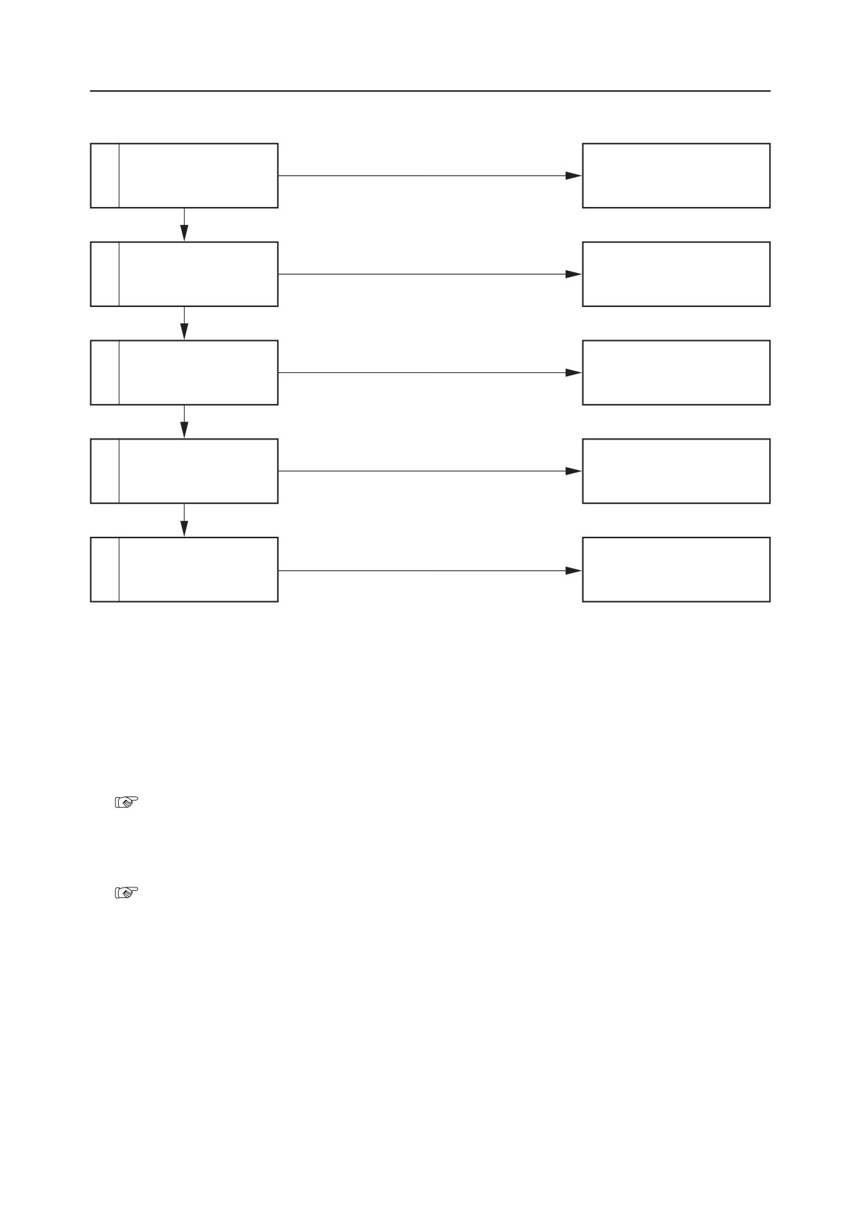
RIGHT OR LEFT SLEWING CANNOT BE DONE.
Faulty
Repair or replace the pilot
1
Inspect the pilot valve.
valve.
Normal
Faulty
Inspect the operation of
Repair or replace the housing
2
the spool.
block.
Normal
Faulty
Inspect the slew relief
Repair or replace the slew re-
3
valve.
lief valve.
Normal
Faulty
Inspect the check valve
Repair or replace the slew
4
of the slew brake valve.
brake valve.
Normal
Repair or replace the slew
5
The slew motor is faulty.
motor.
1. Inspect the pilot valve.
It could be that the spool for only the side of the
pilot valve for which slewing is impossible will
not operate.
“V-10”
2. Inspect the operation of the spool.
It could be that the spool will not move only in the
direction in which slewing is impossible.
“V-10”
TB175W
V-12
SLEWING
TROUBLESHOOTINTG
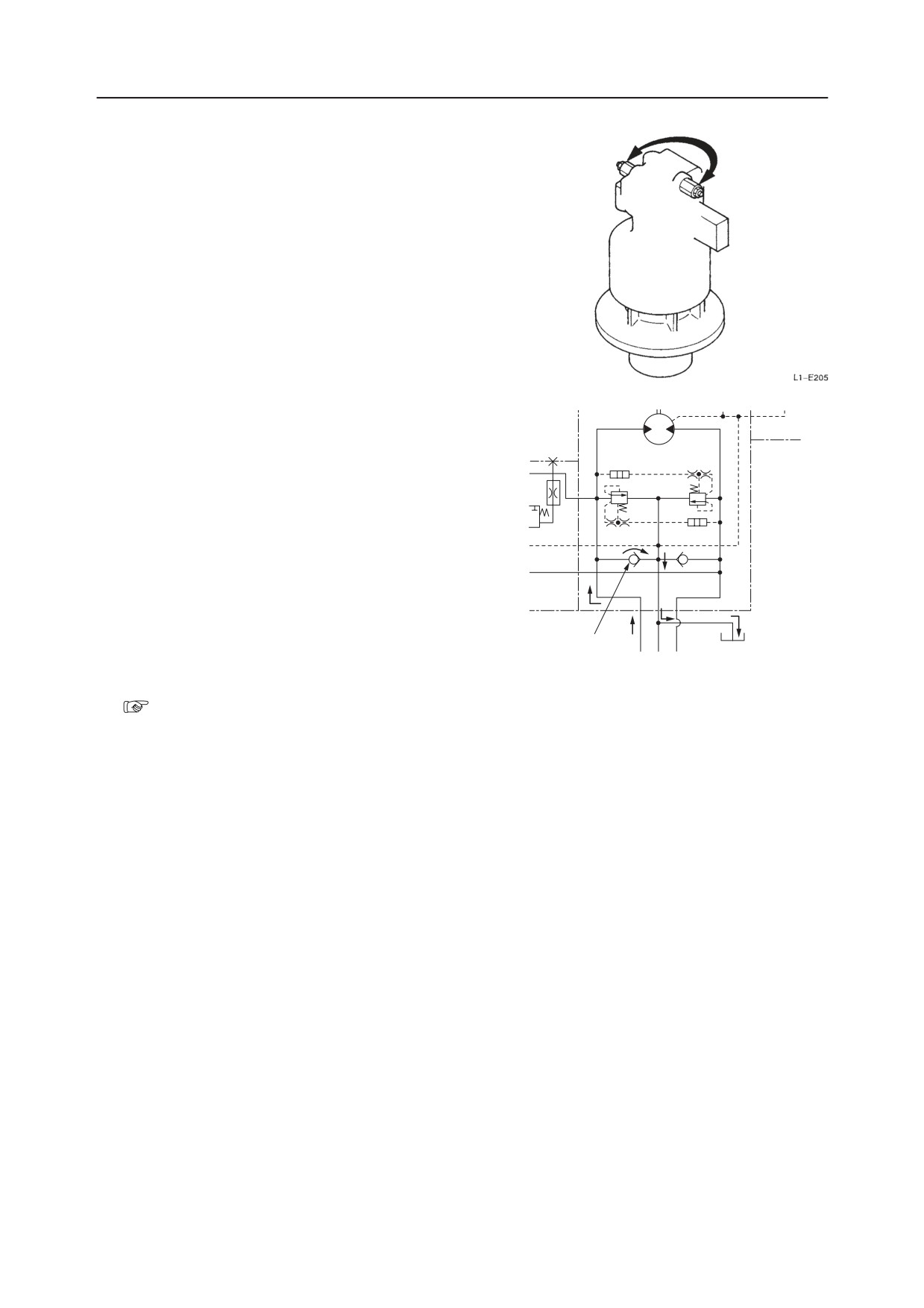
3. Inspect the slew relief valve.
Try switching the left and right slew relief valves.
If slewing becomes possible, the relief valve is
faulty.
4. Inspect the check valve of the slew brake
valve.
If foreign matter is caught in one end of the check
valve (1), or if the valve is sticking, right or left
slewing will be impossible.
• If foreign matter is caught in one of the check
valves, the hydraulic oil returns to the tank
from the check valve.
5. The slew motor is faulty.
“IV. Hydraulic Units, Slew Motor”
V-13
TB175W
TROUBLESHOOTINTG
SLEWING
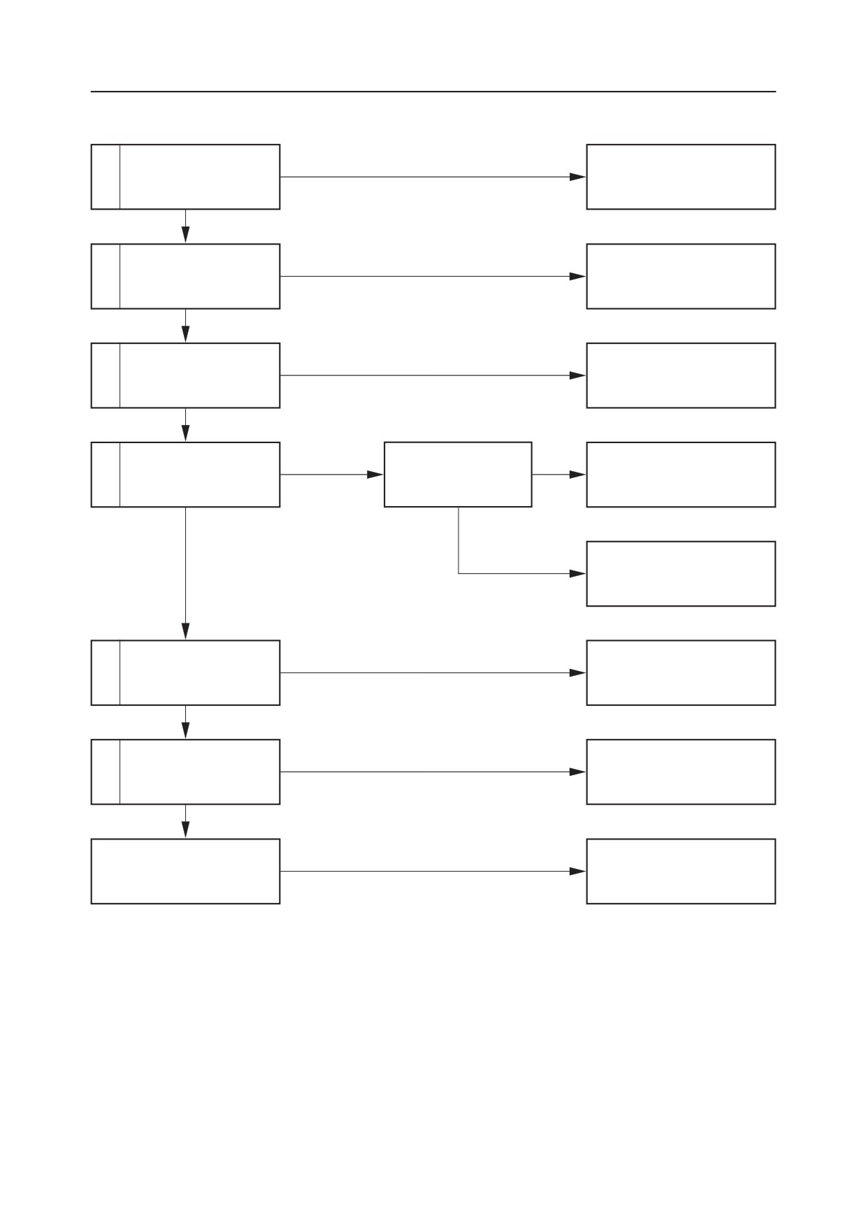
SLEWING SPEED IS LOW, OR THERE IS NO POWER.
Is the time needed for
Within the standard.
1
slewing within the stan-
Normal
dard?
Not within the standard
Faulty
Repair or replace the pilot
2
Inspect the pilot valve.
valve.
Normal
Inspect the operation of
Faulty
Repair or replace the housing
3
the spool.
block.
Normal
Inspect the slew hydrau-
Pressure is low.
Adjust the pressure of
4
Adjust the set pressure.
lic pressure.
the slew relief valve.
Normal
Pressure does not rise.
Repair or replace the slew re-
lief valve.
Inspect the check valve
Faulty
Repair or replace the slew
5
of the slew brake valve.
brake valve.
Normal
Faulty
Repair or replace the slew
6
Inspect the slew motor.
motor.
Normal
The slew bearing is faulty.
Replace.
TB175W
V-14
SLEWING
TROUBLESHOOTINTG
1. Is the time needed for slewing within the
standard?
“II. Specifications, Standards for Judging
Performance”
2. Inspect the pilot valve.
“V-10”
3. Inspect the operation of the spool.
“V-10”
4. Inspect the slew hydraulic pressure.
“V-10”
5. Inspect the check valve of the slew brake
valve.
“IV. Hydraulic Units, Slew Motor”
6. Inspect the slew motor.
“IV. Hydraulic Units, Slew Motor”
V-15
TB175W
TROUBLESHOOTINTG
SLEWING
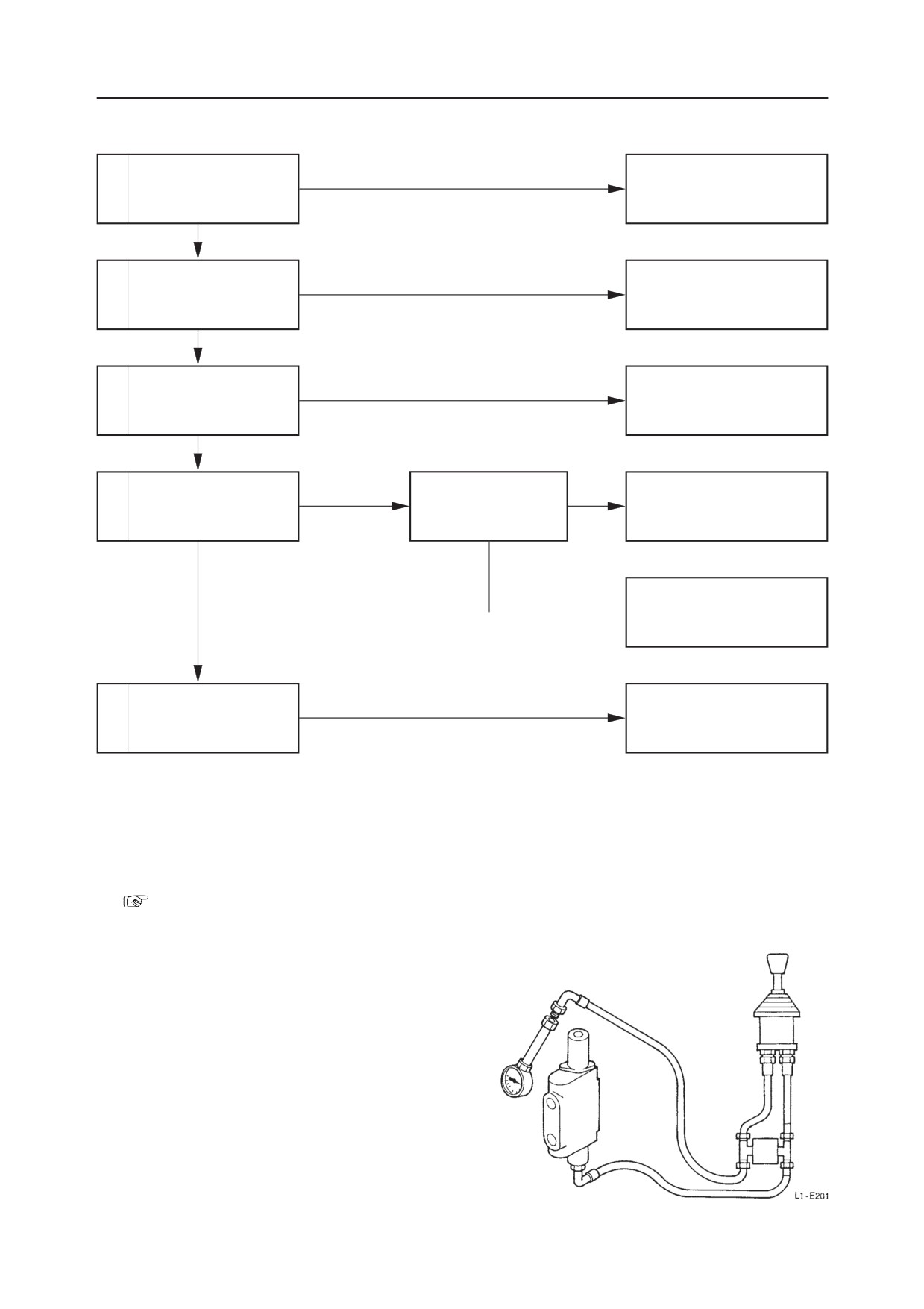
THE MACHINE SLEWS, BUT OVERRUN WHEN SLEWING STOPS IS GREAT, OR IT CANNOT BE STOPPED.
Is the amount of overrun
Within the standard.
1
when slewing stops
Normal.
within the standard?
Not within the standard.
Faulty
Repair or replace the pilot
2
Inspect the pilot valve.
valve.
Normal
Inspect the operation of
Faulty
Repair or replace the housing
3
the spool.
block.
Normal
Inspect the slew hydrau-
Pressure is low.
Adjust the pressure of
4
Adjust the set pressure.
lic pressure.
the slew relief valve.
Normal
Pressure doesn’t rise Repair or replace the slew re-
lief valve.
Inspect the slew brake
Repair replace the slew brake
5
valve.
valve.
1. Is the amount of overrun when slewing stops
within the standard?
“II. Specifications, Standards for Judging
Performance”
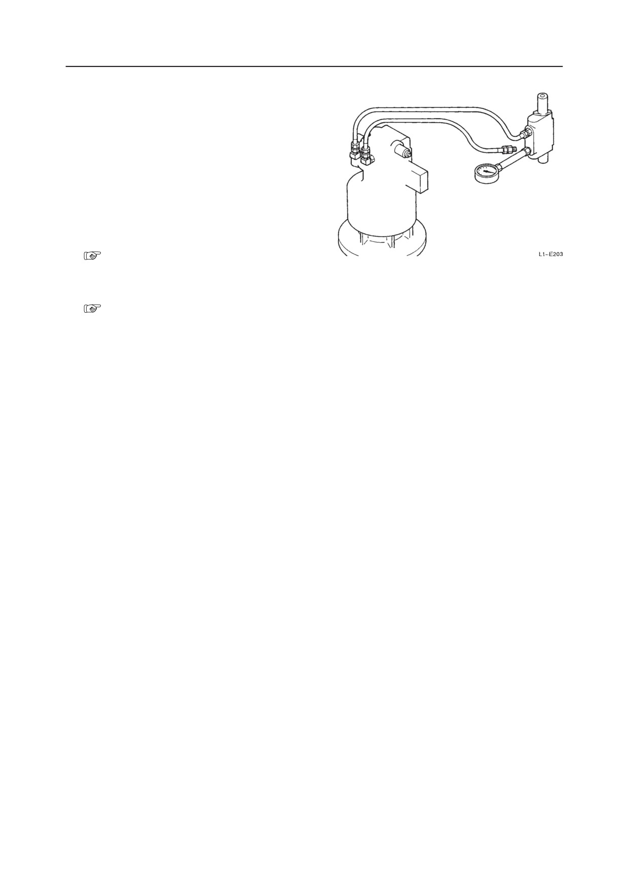
2. Inspect the pilot valve.
Inspect if the spool of the pilot valve returns to the
neutral position when the operation lever (slew)
is released after operation. Disconnect the hose
between the pilot valve and the control valve
(slew section) on the control valve side, then set
a pressure gauge in the disconnected hose.
• Read the pressure gauge after operating the
lever (slew), then releasing it.
• If the pressure is zero, the pilot valve is normal.
TB175W
V-16
SLEWING
TROUBLESHOOTINTG
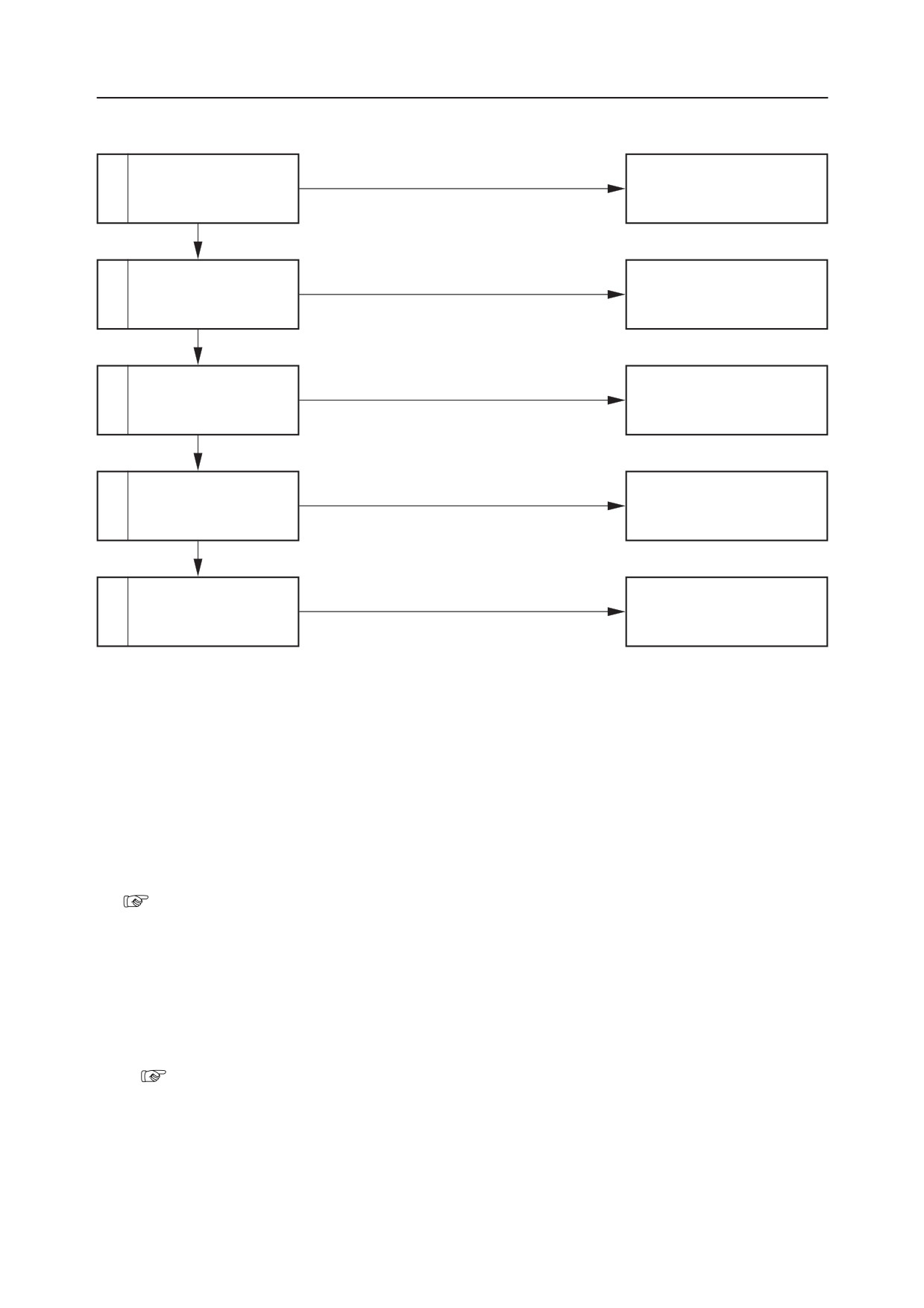
3. Inspect the operation of the spool.
Inspect if the spool of the control valve (slew
section) returns to the neutral position when the
operation lever (slew) is released after operation.
Disconnect the line from the slew section of the
control valve, then set a pressure gauge in its
supply port.
• Read the pressure gauge after operating the
lever (slew), then releasing it.
• If the pressure is zero, the pilot valve is normal.
4. Inspect the slew hydraulic pressure.
“V-10”
5. Inspect the slew brake valve.
“IV. Hydraulic Units, Slew Motor”
V-17
TB175W
TROUBLESHOOTINTG
SLEWING
SLEWING IN SLOW GEAR IS NOT POSSIBLE.
Inspect the hydraulic
Faulty
Repair or replace the hydrau-
1
pump P5.
lic pump P5.
Normal
Faulty
Inspect the pilot relief
Adjust, repair or replace the
2
valve.
pilot relief valve.
Normal
Inspect the slow slew
Faulty
3
Replace the slow slew switch.
switch
Normal
Inspect the slow slew
Faulty
Repair or replace the slow slew
4
solenoid valve.
solenoid valve.
Normal
Inspect the slew flow
Faulty
Repair or replace the slew flow
5
control valve.
control valve.
1. Inspect the hydraulic pump P5.
Inspect the hydraulic pump P5 which is the source
of the hydraulic pressure for switching to slow
gear.
“V-4”
Since clogging of the line filter can also be con-
sidered, inspect and clean the filter.
2. Inspect the pilot relief valve.
Measure the relief pressure of the pilot relief
valve.
• If the pressure is the standard value, the valve
is normal.
“II. Specifications Standards for Judging
Performance”
3. Inspect the slow slew switch.
Press the switch to obtain “ON” condition. The
switch is normal when the lamp lights in this
condition.
TB175W
V-18
SLEWING
TROUBLESHOOTINTG
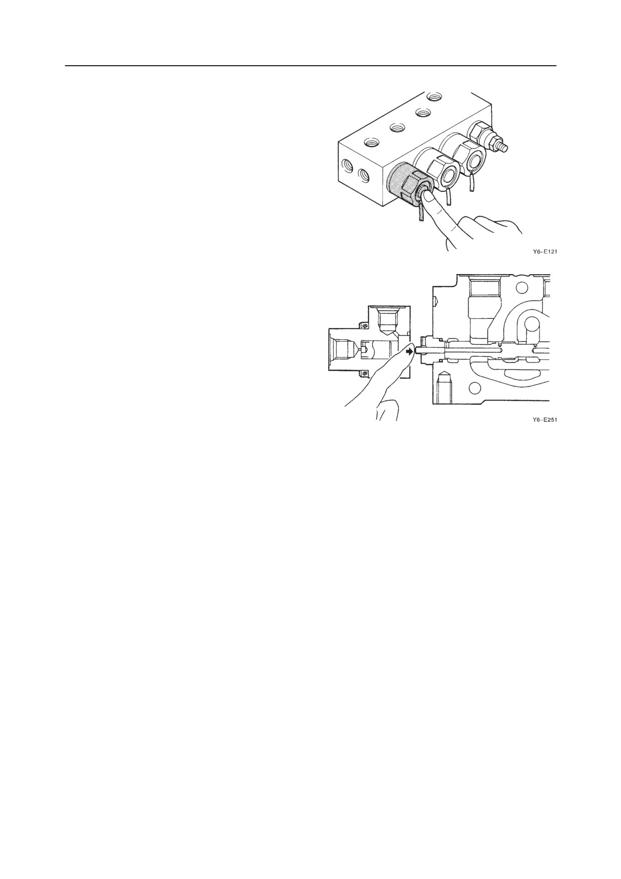
4. Inspect the slow slew solenoid valve.
a. Turn the start switch “ON”.
b. Press the protruding portion of the solenoid
valve lightly.
c. Turn the slow slew switch “ON”.
d. If the spool moves and vibration can be felt
with the fingertip when the circuit changes,
then it is normal.
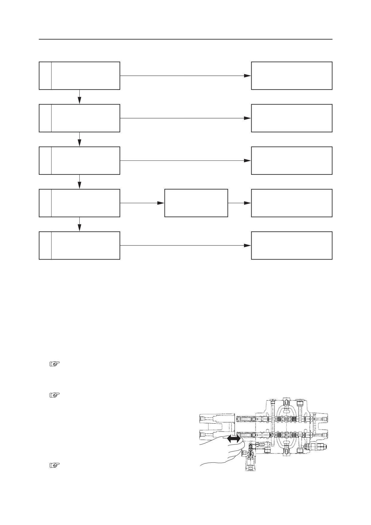
5. Inspect the slew flow control valve.
Inspect if the spool of the slew flow control valve
moves smoothly.
• Remove the spool cover at the FC port and try
pushing the spool with a finger. It is normal if
it moves smoothly about 9 mm.
V-19
TB175W
TROUBLESHOOTINTG
BOOM
THE BOOM CYLINDER DOESN’T MOVE.
Inspect the operation of
1
actuators other than the
boom cylinder.
Normal
Faulty
Repair or replace the pilot
2
Inspect the pilot valve.
valve.
Normal
Inspect the operation of
Faulty
Repair or replace the housing
3
the spool.
block.
Normal
Operation
Perform a port relief
became normal.
The port relief valve is
Repair or replace the port re-
4
valve switching test.
faulty.
lief valve.
Does not change.
Inspect the boom cylin-
Faulty
Repair or replace the boom
5
der.
cylinder.
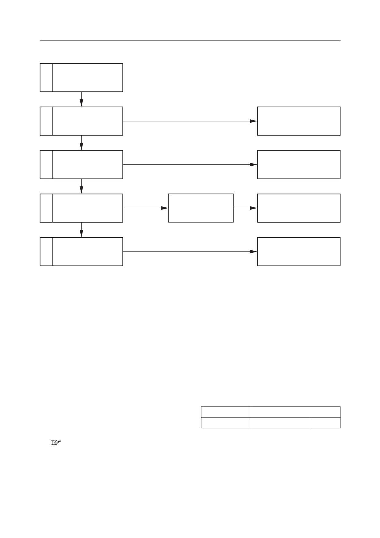
1. Inspect the operation of actuators other than
the boom cylinder.
Inspect if the operation of the boom cylinder only
Lever Operated
Places inspected
is faulty by the table at right. If its operation is
Bucket
Relief Valve R1
Pump P1
faulty, inspect the main relief valve and the hy-
draulic pump.
“V-6”
TB175W
V-20
BOOM
TROUBLESHOOTINTG
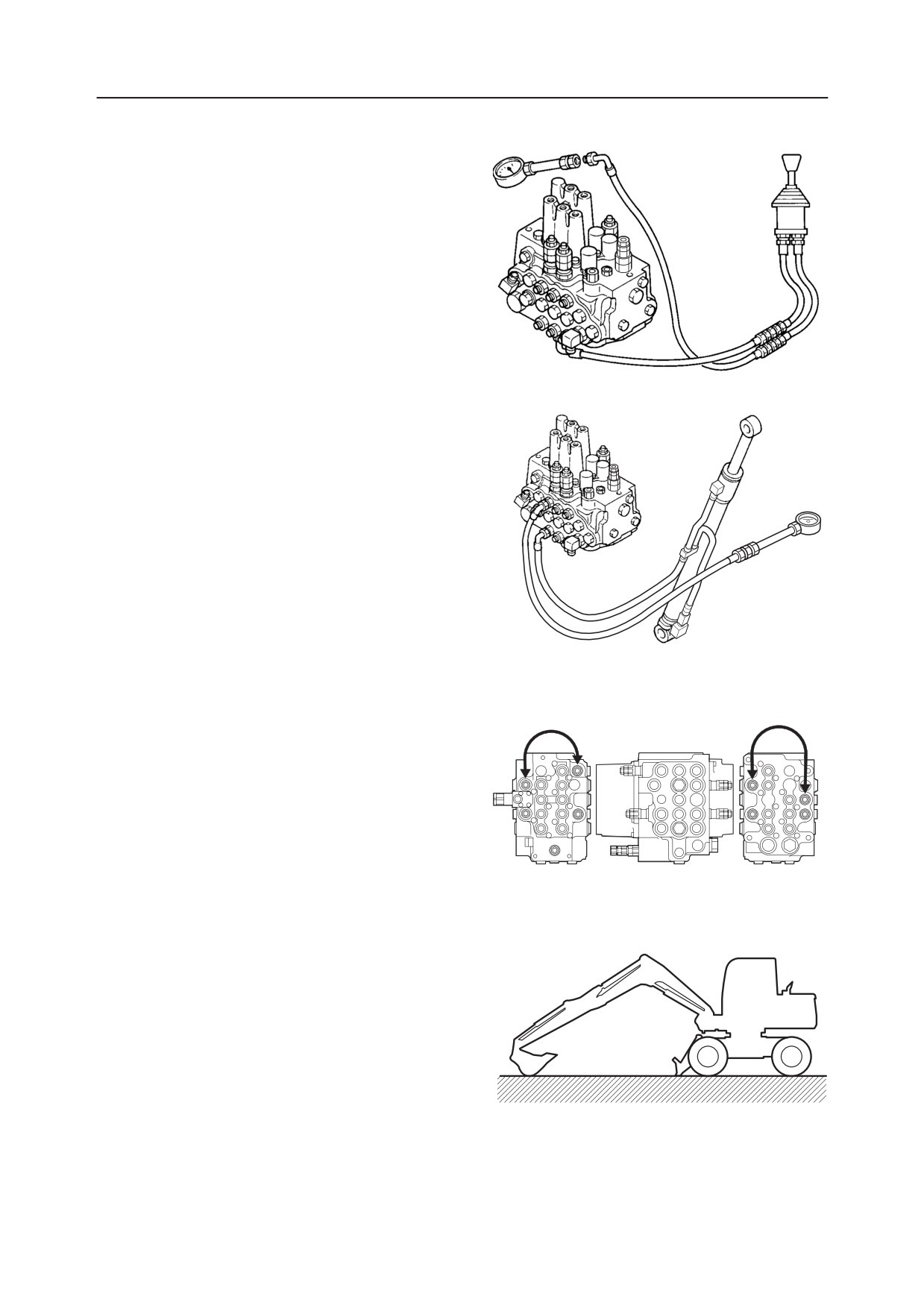
2. Inspect the pilot valve.
Disconnect the hose between the pilot valve and
control valve (boom section) on the control valve
side, then set a pressure gauge in the disconnected
hose.
• Operate the (boom) lever and measure the
pressure.
• Depending the operation angle, if the pressure
is normal, it will range between 0~3.4 MPa.
W2E004
3. Inspect the operation of the spool.
Disconnect the hose between the control valve
(boom section) and the cylinder on the cylinder
side, then set a pressure gauge in the disconnected
hose.
• Operate the (boom) lever and measure the
pressure.
• A pressure of 27.5 MPa is normal.
W2E005
4. Perform a port relief valve switching test.
Switch the port relief valve for the port relief
valve of the normal arm. If the boom cylinder
operates, the boom side port relief valve is faulty.
W2E006
5. Inspect the boom cylinder.
a. Disconnect the hose between the control valve
and the boom cylinder on the control valve
side.
b. Connect the disconnected hose to the arm
section or the bucket section.
c. Try operating the boom cylinder. If the cylin-
der doesn’t operate, the cylinder is faulty.
When performing the operation in “a~c”
above, the bucket cylinder should be fully
W1-E004
extended, the arm cylinder should be fully
retracted and the bucket should be lowered
to the ground.
V-21
TB175W
TROUBLESHOOTINTG
BOOM
BOOM CYLINDER OPERATION IS SLOW, OR THERE IS NO POWER.
Is the boom cylinder’s
Within the standard.
1
speed within the stan-
Normal
dard?
Not within the standard.
Faulty
Repair or replace the pilot
2
Inspect the pilot valve.
valve.
Normal
Inspect the operation of
Faulty
Repair or replace the housing
3
the spool.
block.
Normal
Operation
Perform a port relief
became normal.
The port relief valve is
Repair or replace the port re-
4
valve switching test.
faulty.
lief valve.
Does not change
Inspect the boom cylin-
Faulty
Repair or replace the boom
5
der.
cylinder.
1. Is the boom cylinder’s speed within the stan-
dard?
“II. Specifications, Standards for Judging
Performance”
2. Inspect the pilot valve.
“V-21”
3. Inspect the operation of the spool.
Stroke the spools of the boom [1] and boom [2]
sections and inspect whether they move smoothly,
or remove the spools and check whether there is
any foreign matter engaged in them.
4. Perform a port relief valve switching test.
“V-21”
TB175W
V-22
BOOM
TROUBLESHOOTINTG
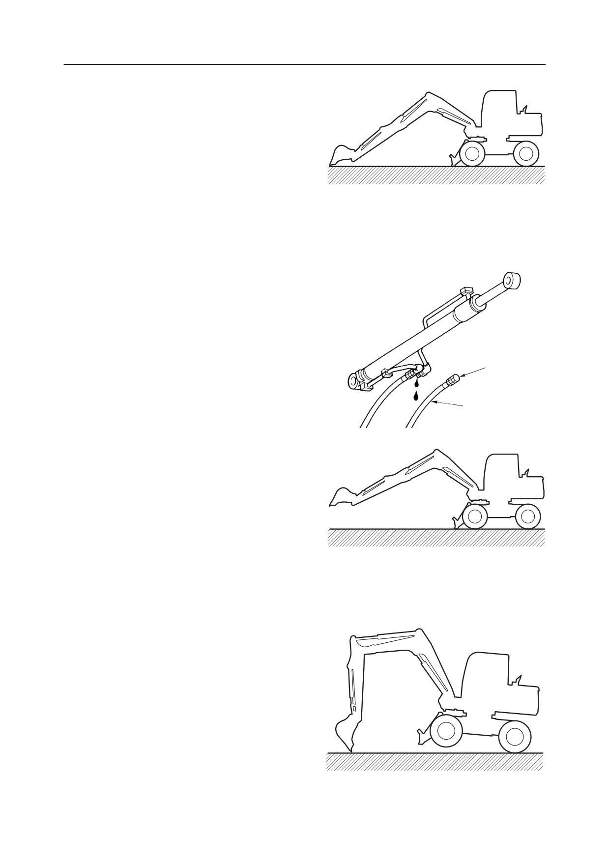
5. Inspect the boom cylinder.
Boom Cylinder internal Leakage Inspect (1)
a. With the bucket cylinder fully retracted and
with the rod of the arm cylinder a little ex-
tended from the fully retracted position, lower
the bucket front end to the ground.
W1-E005
b. Disconnect the rod side hose (A) only and let
the oil in the piping run out.
Insert a plug (1) in the disconnected hose.
• Test the left and right cylinders one at a
time. Remove both hoses from the cylinder
that is not being inspected at this time and
plug the disconnected hoses.
c. Retract the arm cylinder and lift the bucket so
it is floating above the ground.
At this time, if there is oil leaking from the
piping of the cylinder where the hose was
disconnected, and if the boom cylinder’s rod is
retracted, the cylinder is leaking internally.
Also, if there is no leakage of oil from the
cylinder’s piping, if the boom cylinder’s rod is
retracted, the control valve is leaking inter-
nally.
W1-E006
Boom Cylinder Internal Leakage Inspect (2)
a. Place the machine in the posture shown in the
figure.
W1-E008
V-23
TB175W
TROUBLESHOOTINTG
BOOM
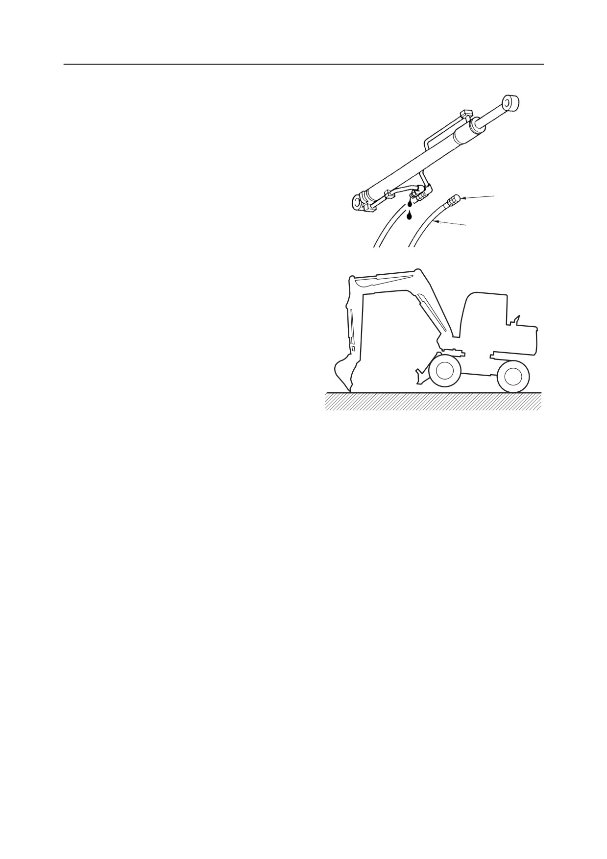
b. Disconnect the head side hose (B) and let the
hydraulic oil out of the cylinder’s piping.
Insert a plug (2) in the disconnected hose.
• Test the left and right cylinders one at a
time. Remove both hoses from the cylinder
that is not being inspected at this time and
plug the disconnected hoses.
c. Operate the bucket and raise the machine’s
body.
At this time, if there is oil leaking from the
piping of the cylinder where the hose was
disconnected, and if the boom cylinder’s rod is
extended, the cylinder is leaking internally.
Also, if there is no leakage of oil from the
cylinder’s piping, if the boom cylinder’s rod is
extended, the control valve is leaking inter-
nally.
If the cylinder is damaged internally, the
system should be flushed out to remove any
W1-E008
broken pieces (NAS Class 9).
TB175W
V-24
BOOM
TROUBLESHOOTING
WHEN THE BOOM OPERATION LEVER IS PULLED GENTLY, THE BOOM DROPS TEMPORARILY.
Inspect the load check
Faulty
Repair or replace the housing
1
valve of the control valve.
block.
Normal
Inspect for internal leak-
Faulty
Repair or replace the boom
2
age in the boom cylinder.
cylinder.
1. Inspect the load check valve of the control
valve.
a. Disconnect the hose between the control valve
and boom cylinder at the control valve side.
b. Connect the disconnected hose to the arm or
bucket section.
c. Try operating the boom cylinder.
If operation is normal, the load check valve is
faulty.
Place the machine in the following posture
when performing the operation in “a~c” above.
• The bucket cylinder should be fully ex-
tended, the arm cylinder should be fully
retracted and the bucket should be low-
ered to the ground.
Reference: When the spool first starts to pull, the
oil’s pressure and flow are small, so if the load
check valve is faulty, it causes a load to bear on the
boom cylinder, which causes the oil to flow
backwards for a time. For this reason, the boom
will drop temporarily.
2. Inspect for internal leakage in the boom
cylinder.
When the boom cylinder’s piston or tube is faulty,
if oil is leaking from the head side (A) to the rod
side (B), since the oil’s pressure and flow are low
when the spool first starts pulling, the boom
cylinder will drop temporarily. Also, the cylinder
will have inadequate driving force. However, in
this case as well, the amount of natural drop will
be great.
• Cylinder Inspect
“V-23~24”
V-25
TB175W
TROUBLESHOOTING
BOOM
THE AMOUNT OF BOOM NATURAL DROP IS GREAT.
Is the amount of natural
Within the standard.
1
Normal
fall within the standard?
Not within the standard.
Inspect for internal leak-
Faulty
Repair or replace the boom
2
age in the boom cylinder.
cylinder.
Normal
Operation be-
Perform a port relief
came normal.
The port relief valve is
Repair or replace the port re-
3
valve switching test.
faulty.
lief valve.
Does not change.
The control valve is leaking
Replace the housing block.
internally.
1. Is the amount of natural drop within the
standard?
“II. Specifications, Standards for Judging
Performance”
2. Inspect for internal leakage in the boom
cylinder.
“V-23~24”
3. Perform a port relief valve switching test.
“V-21”
TB175W
V-26
BOOM
TROUBLESHOOTING
THE BOOM ADJUSTMENT CYLINDER DOESN’T MOVE.
Inspect the supply pres-
1
sure to the pilot valve
(swing).
Normal
Inspect the pilot valve
Faulty
Repair or replace the pilot
2
(swing).
valve (swing).
Normal
Inspect the operation of
Faulty
Repair or replace the housing
3
the spool.
block.
Normal
Faulty
Repair or replace the selector
4
Inspect the selector valve.
valve.
Normal
Inspect the port relief
Faulty
Repair or replace the port rerief
5
valve.
valve.
Normal
Inspect the boom adjust-
Faulty
Repair or replace the boom
6
ment cylinder.
adjustment cylinder.
1. Inspect the supply pressure to the pilot valve
5Pb1
(swing).
“V-7~8”
2. Inspect the pilot valve (swing).
Disconnect the hose between the pilot valve
(swing) and control valve on the control valve
5Pa1
side, then set a pressure gauge in the disconnected
hose.
• Operate the boom swing pedal and measure the
pressure.
BS2
• Depending the operation angle, if the pressure
BS1
is normal, it will range between 0~3.4 MPa.
W2E007
V-27
TB175W
TROUBLESHOOTING
BOOM
3. Inspect the operation of the spool.
Disconnect the hose between the control valve
SH
(swing section) and the selector valve on the
selector valve side, then set a pressure gauge in
the disconnected hose.
5B1
5A1
• Operate the boom swing pedal and measure the
SR
OP2
pressure.
• A pressure of 27.5 MPa is normal.
MA1
MA2
OP1
MA1
MP1
MB1
MA2
MP2
MB2
W2E008
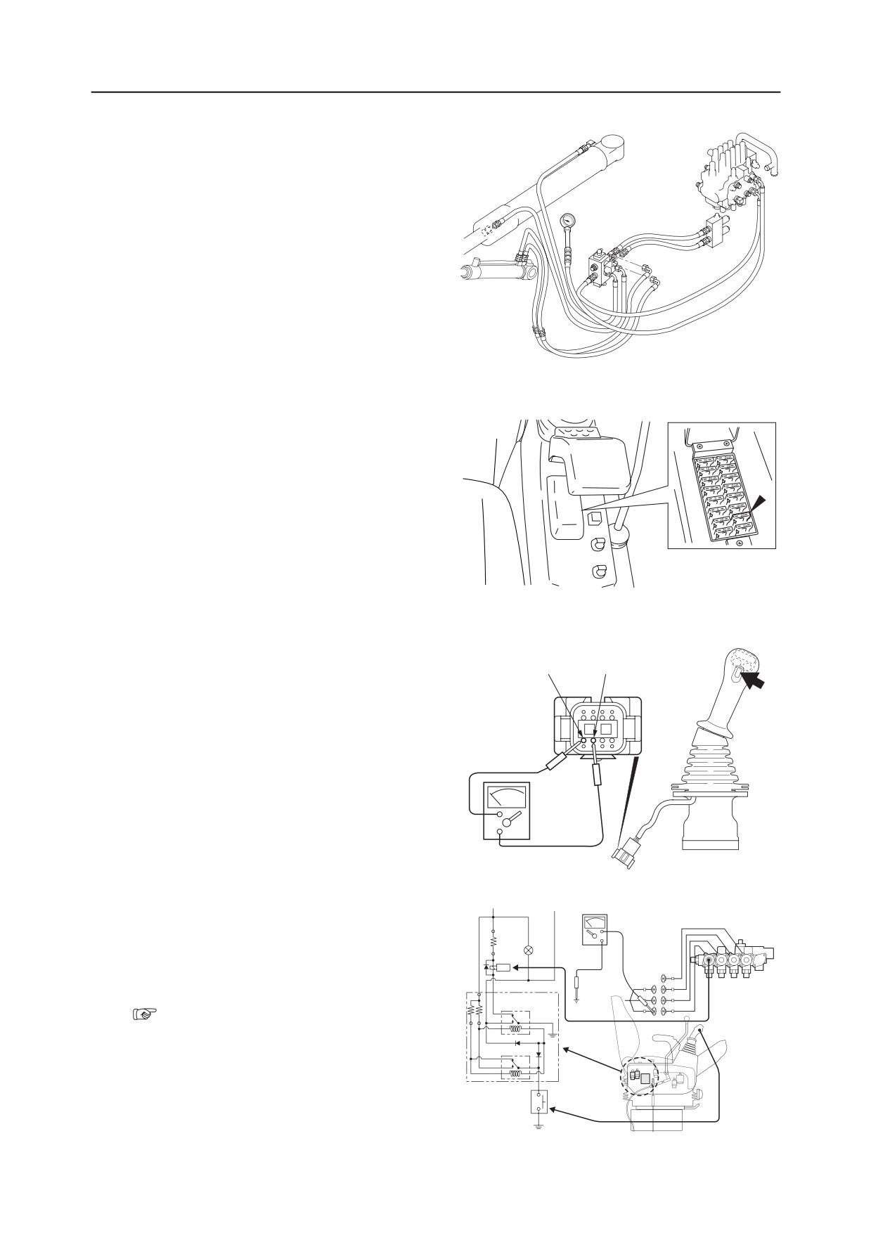
4. Inspect the selector valve.
a. Inspect the fuse.
Operate the solenoid valve and check the fuse
for the power supply circuit.
b. Inspect the selector switch.
Press the selector switch to turn it “ON”. While
GRAY YELLOW
it is this condition, check if there is continuity
with a tester.
W2E009E
c. Inspect the relay.
Solenoid Valve (4-Section)
Press the selector switch to turn the relay to
Change and Speed Shift
“ON”. Check whether the voltage is applied to
the solenoid valve by using a tester. Be sure to
stop the engine before starting the inspection.
d. Inspect the solenoid valve.
“IV. Hydraulic Units, Solenoid Valves,
Swing/Adjust Cange”
W2E010E
TB175W
V-28
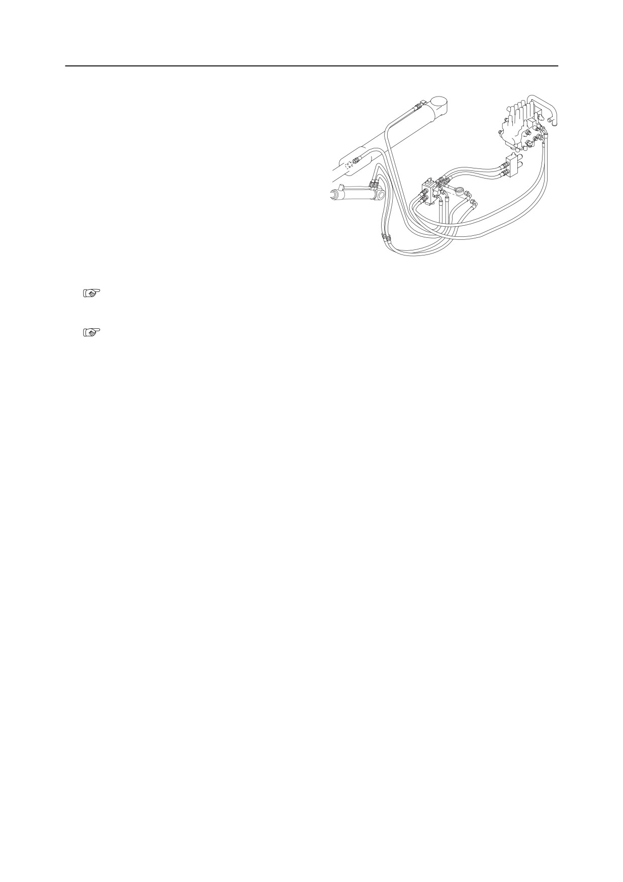
BOOM
TROUBLESHOOTING
e. Inspect the operation of the spool.
Disconnect the hose between the selector valve
SH
and the cylinder on the selector valve side, then
set a pressure gauge in the disconnected hose.
• Operate the boom swing pedal and measure
5B1
5A1
the pressure.
SR
OP2
• A pressure of 33.3 MPa is normal.
MA1
MA2
OP1
MP1
MA1
MB1
MA2
MP2
MB2
W2E011
5. Inspect the port relief valve.
“IV. Hydraulic Units, Port Relief Valve”
6. Inspect the boom adjustment cylinder.
“IV. Hydraulic Units, Cylinders”
V-29
TB175W
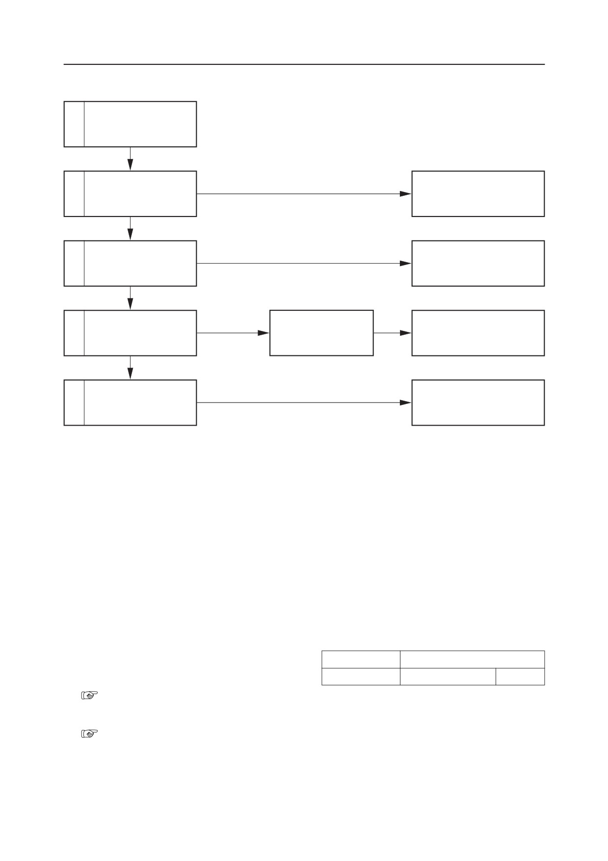
TROUBLESHOOTING
ARM
THE ARM CYLINDER DOESN’T MOVE.
Inspect the operation of
1
actuators other than the
arm cylinder.
Normal
Faulty
Repair or replace the pilot
2
Inspect the pilot valve.
valve.
Normal
Inspect the operation of
Faulty
Repair or replace the housing
3
the spool.
block.
Normal
Operation
Perform a port relief
became normal.
The port relief valve is
Repair or replace the port re-
4
valve switching test.
faulty.
lief valve.
Does not change.
Faulty
Repair or replace the arm cyl-
5
Inspect the arm cylinder.
inder.
1. Inspect the operation of actuators other than
the arm cylinder.
Inspect if the operation of the arm only is faulty by
Lever Operated
Places inspected
the table at right. If operation is faulty, inspect the
Swing
Relief Valve R1
Pump P2
main relief valve and the hydraulic pump.
“V-6”
2. Inspect the pilot valve.
“V-21”
TB175W
V-30
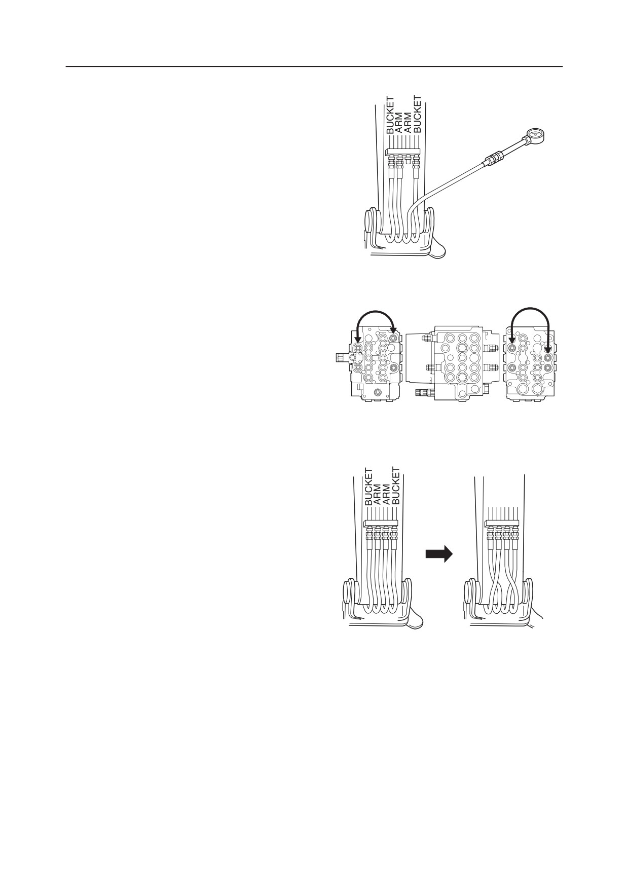
ARM
TROUBLESHOOTING
3. Inspect the operation of the spool.
Disconnect the arm hose connected to the pipe at
the boom foot, then set a pressure gauge in the
disconnected hose.
• Operate the (arm) lever and measure the pres-
sure.
• If the pressure is 27.5 MPa, it is normal.
4. Perform a port relief valve switching test.
Switch the port relief valve with that of the
normal boom. If the arm cylinder then operates,
the port relief valve is faulty.
W2E006
5. Inspect the arm cylinder.
Switch the arm hoses and bucket hoses connected
to the pipes at the boom foot.
• Try operating the (bucket) operation lever to
operate the arm cylinder.
• If the cylinder doesn’t operate, the cylinder is
faulty.
When performing the operation above, the
bucket cylinder should be fully extended, the
arm cylinder should be fully retracted, and
the bucket should be lowered to the ground.
V-31
TB175W
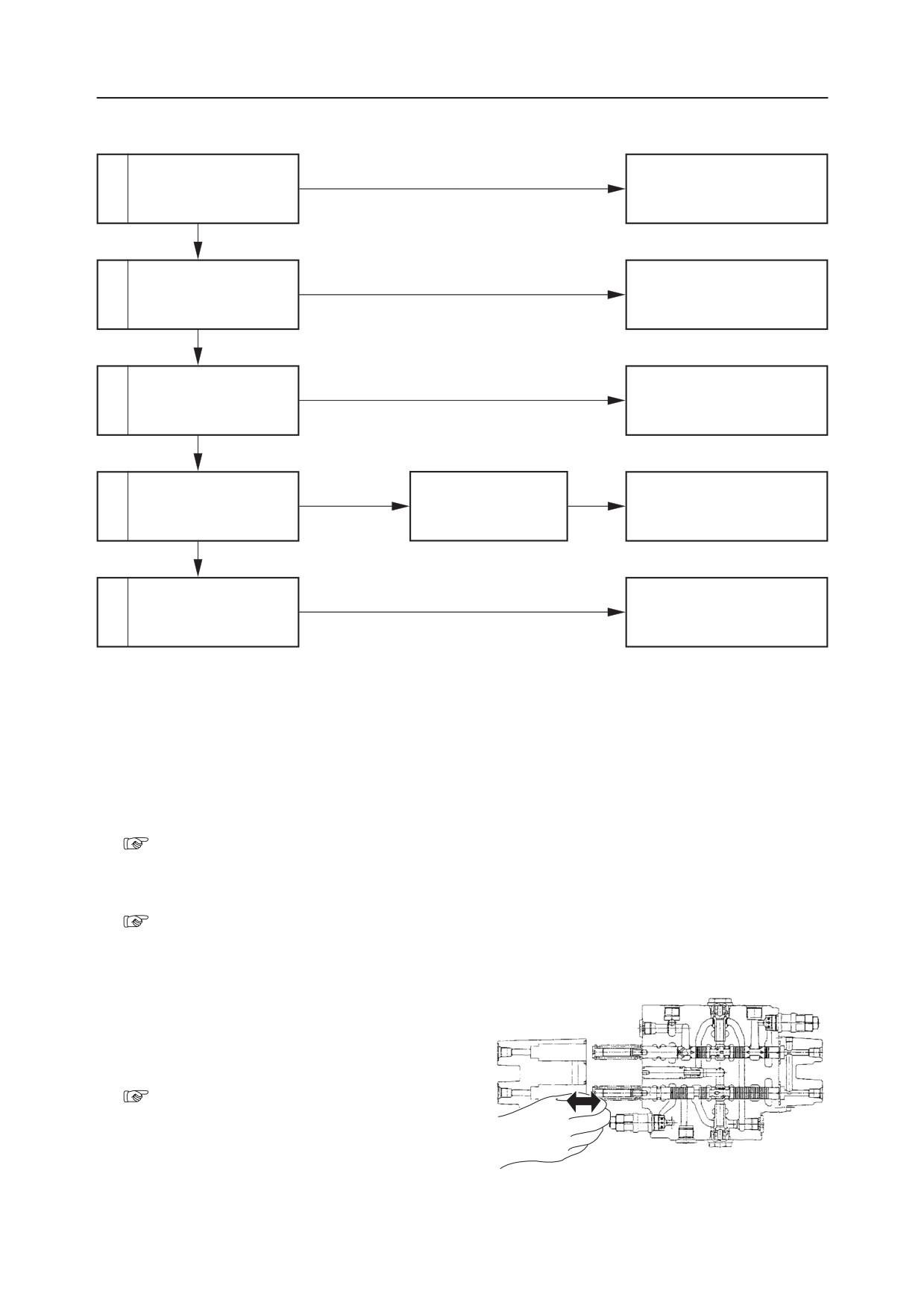
TROUBLESHOOTING
ARM
ARM CYLINDER OPERATION IS SLOW, OR THERE IS NO POWER.
Is the arm cylinder’s
Within the standard.
1
speed within the stan-
Normal
dard?
Not within the standard.
Faulty
Repair or replace the pilot
2
Inspect the pilot valve.
valve.
Normal
Inspect the operation of
Faulty
Repair or replace the housing
3
the spool.
block.
Normal
Operation
Perform a port relief
became normal.
The port relief valve is
Repair or replace the port re-
4
valve switching test.
faulty.
lief valve.
Does not change
Faulty
Repair or replace the arm cyl-
5
Inspect the arm cylinder.
inder.
1. Is the arm cylinder’s speed within the stan-
dard?
“II. Specifications, Standards for Judging
Performance”
2. Inspect the pilot valve.
“V-21”
3. Inspect the operation of the spool.
Stroke the spools of the boom [1] and boom [2]
sections and inspect whether they move smoothly,
or remove the spools and check whether there is
any foreign matter engaged in them.
4. Perform a port relief valve switching test.
“V-21”
TB175W
V-32
ARM
TROUBLESHOOTING
5. Inspect the arm cylinder.
a. Fully retract the bucket cylinder, fully retract
the arm cylinder and lower the bucket to the
ground.
W1-E005
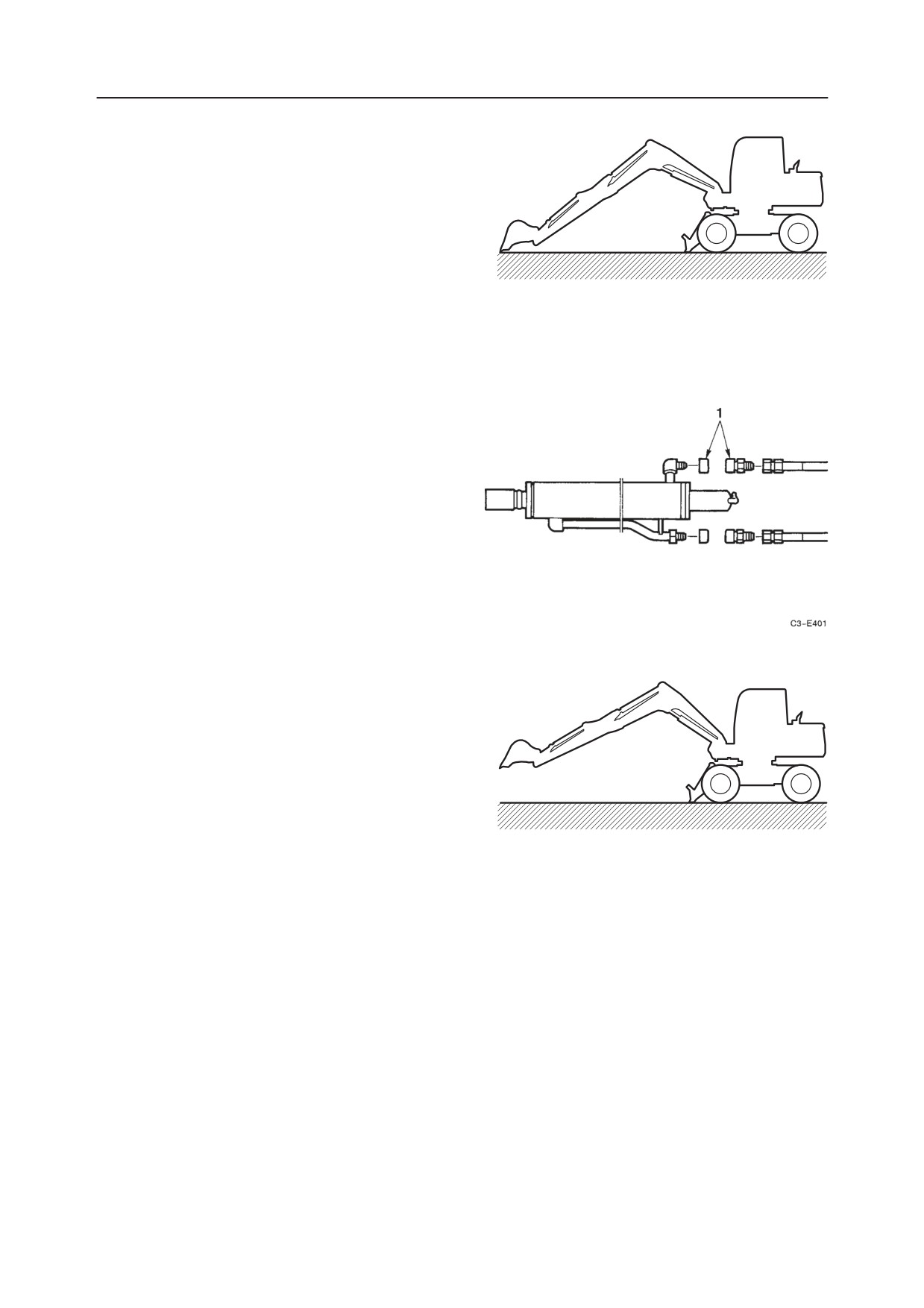
b. Disconnect the two hoses connected to the
cylinder. Insert plugs (1) in the disconnected
hoses and the cylinder piping.
c. Raise the boom and raise the hoe attachment so
it floats above the ground. If the arm dorps, the
cylinder is faulty. If the arm does not drop,
there is leakage inside the control valve.
W1-E006
V-33
TB175W
TROUBLESHOOTING
ARM
THE AMOUNT OF ARM NATURAL DROP IS GREAT.
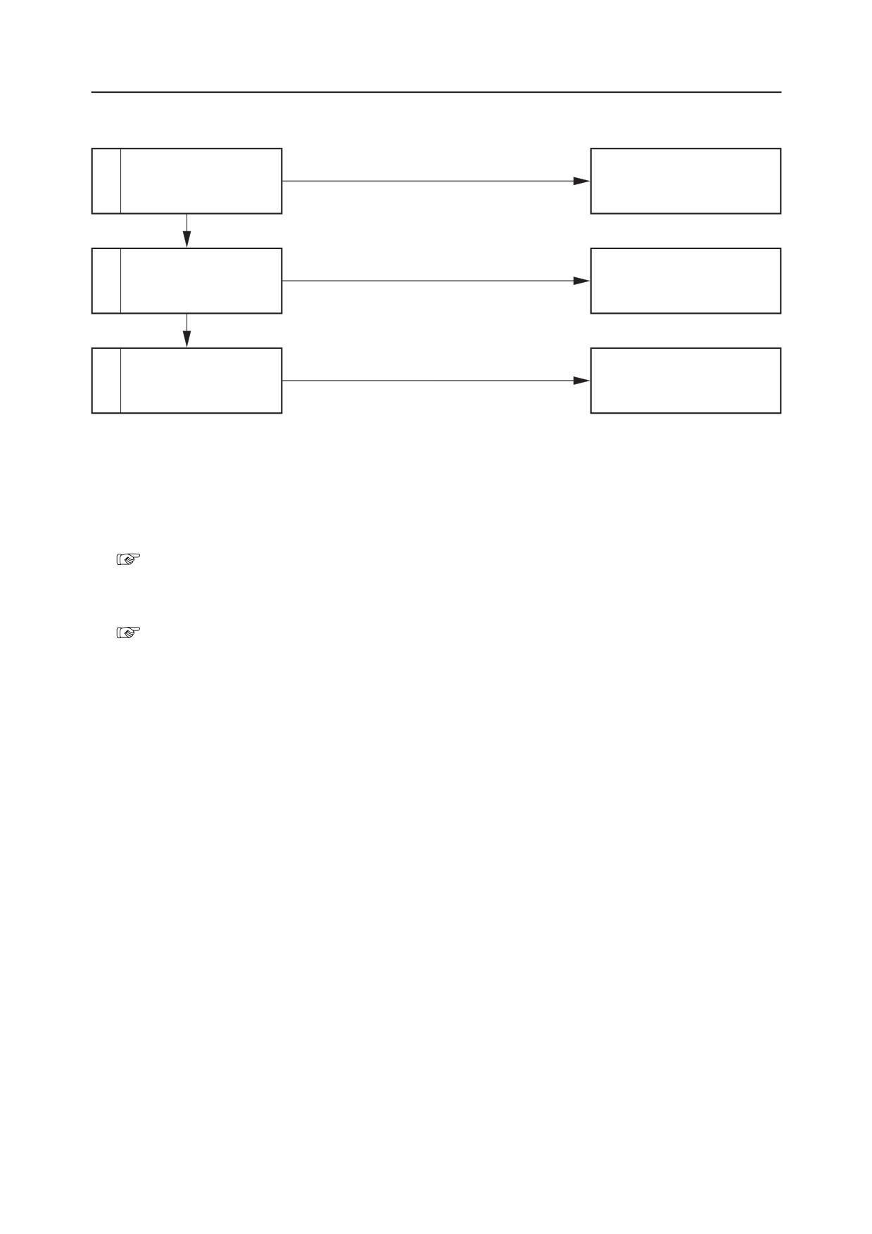
Is the amount of natural
Within the standard.
1
Normal
fall within the standard?
Not within the standard.
Faulty
Repair or replace the arm cyl-
2
Inspect the arm cylinder.
inder.
Normal
There is leakage inside
3
Replace the housing block.
the control valve.
1. Is the amount of natural fall within the stan-
dard?
“II. Specifications, Standards for Judging
Performance”
2. Inspect the arm cylinder.
“V-31”
TB175W
V-34
BUCKET
TROUBLESHOOTING
THE BUCKET CYLINDER DOESN’T MOVE, OR THERE IS NO POWER.
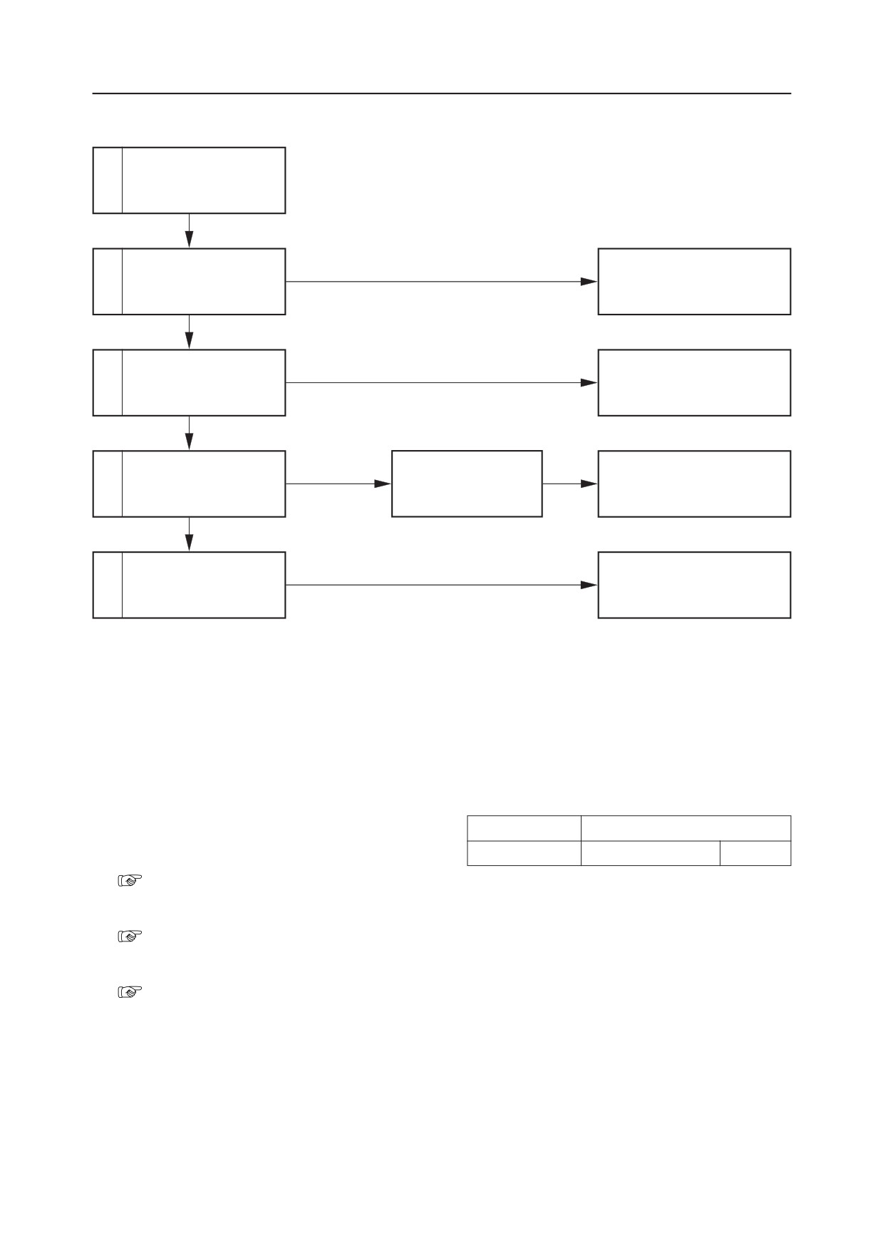
Inspect the operation of
1
actuators other than the
bucket cylinder.
Normal
Faulty
Repair or replace the pilot
2
Inspect the pilot valve.
valve.
Normal
Inspect the operation of
Faulty
Repair or replace the housing
3
the spool.
block.
Normal
Operation
Perform a port relief
became normal.
The port relief valve is
Repair or replace the port re-
4
valve switching test.
faulty.
lief valve.
Does not change.
Inspect the bucket cylin-
Faulty
Repair or replace the bucket
5
der.
cylinder.
1. Inspect the operation of actuators other than
the bucket cylinder.
Inspect if the operation of the bucket only is faulty
Lever Operated
Places inspected
by the table at right. If operation is faulty, inspect
Boom
Relief Valve R1
Pump P1
the main relief valve and the hydraulic pump.
“V-6”
2. Inspect the pilot valve.
“V-21”
3. Inspect the operation of the spool.
“V-21”
V-35
TB175W
TROUBLESHOOTING
BUCKET
4. Perform a port relief valve switching test.
When only “bucket load” side is inoperable:
Replace the port relief valve with that of the
normal boom, and test. If the bucket cylinder
operates, the replaced old port relief valve was
faulty.
W2E012
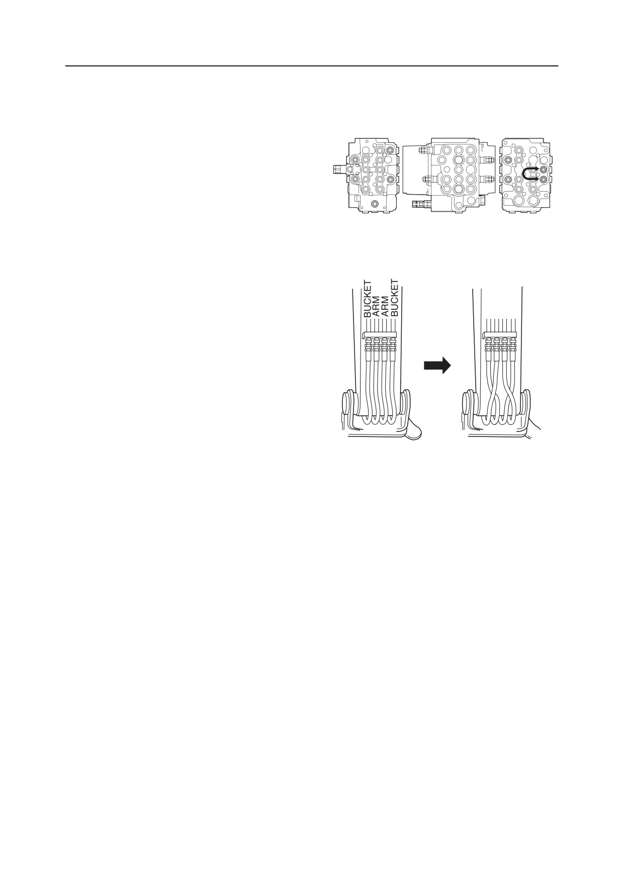
5. Inspect the bucket cylinder.
At the boom foot, exchange the arm hose with the
bucket hose that is connected to the pipe.
• Move the lever (arm) and check whether the
bucket cylinder operates.
• If the bucket cylinder does not operate, the
bucket cylinder is faulty.
This inspection should be done with the
bucket cylinder fully extended and the arm
cylinder fully retracted. Also, the bucket must
be lowered to the ground.
TB175W
V-36
BUCKET
TROUBLESHOOTING
THE AMOUNT OF BUCKET NATURAL DROP IS GREAT.
Is the amount of natural
Within the standard.
1
Normal
fall within the standard?
Not within the standard.
Inspect the bucket cylin-
Faulty
Repair or replace the bucket
2
der.
cylinder.
Normal
There is leakage inside
3
Replace the housing block.
the control valve.
1. Is the amount of natural drop within the
standard?
“II, Specifications, Standards for Judging
Performance”
2. Inspect the bucket cylinder.
a. Fully extend the bucket cylinder, fully retract
the arm cylinder and lower the bucket to the
ground,
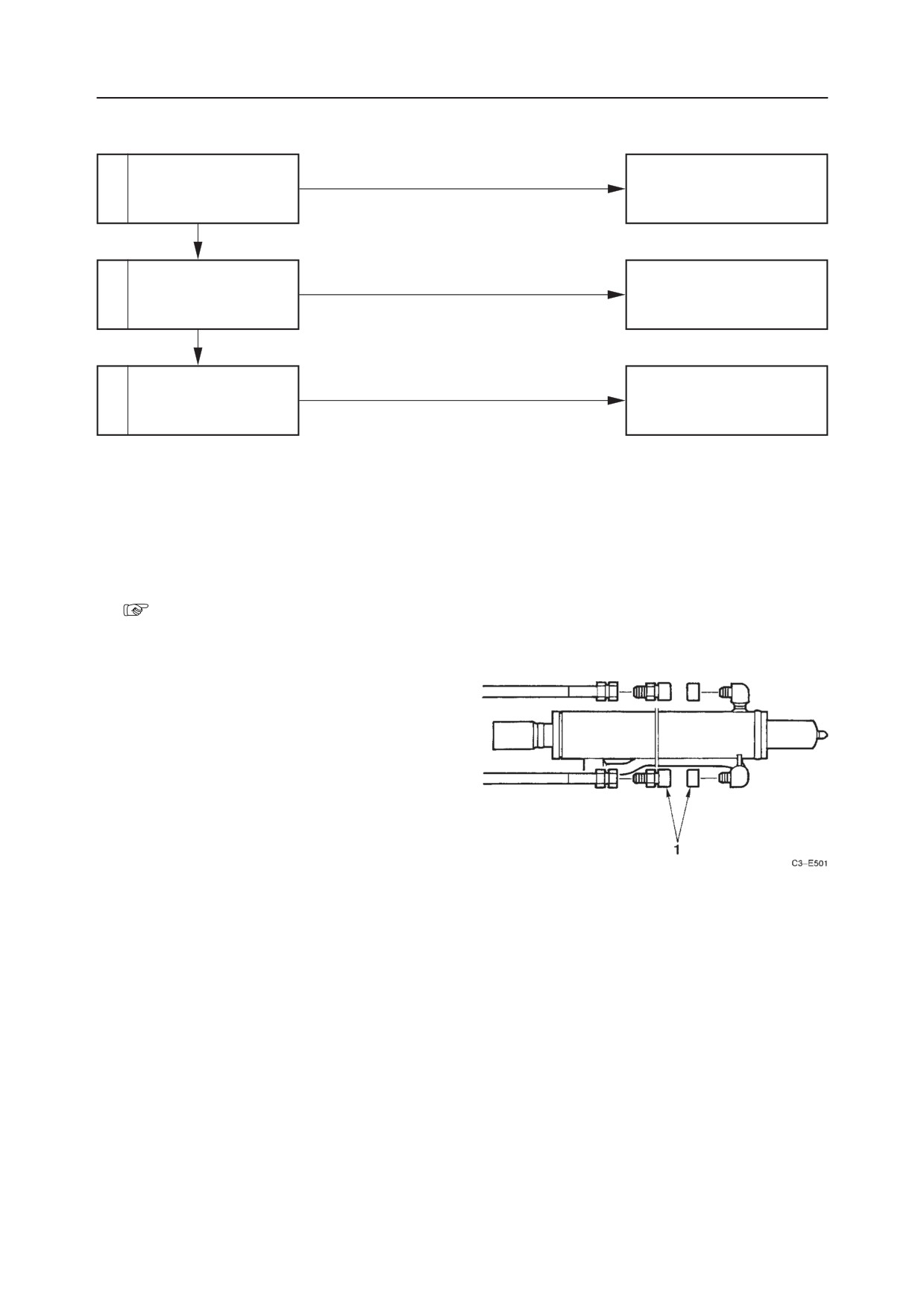
b. Disconnect the 2 hoses connected to the cylin-
der.
Insert the plugs (1) in the disconnected hoses
and the piping.
c. Raise the boom and raise the hoe attachment so
that it floats above the ground, If the bucket
drops, the cylinder is faulty, If the bucket does
not drop, there is leakage inside the control
valve.
V-37
TB175W
TROUBLESHOOTING
BOOM SWING
THE SWING CYLINDER DOESN’T MOVE.
2-Piece Boom
Inspect the supply pres-
1
sure to the pilot valve
(swing).
Normal
Inspect the pilot valve
Faulty
Repair or replace the pilot
2
(swing).
valve (swing).
Normal
Inspect the operation of
Faulty
Repair or replace the housing
3
the spool.
block.
Normal
Faulty
Repair or replace the selector
4
Inspect the selector valve.
valve.
Normal
Inspect the swing cylin-
Faulty
Repair or replace the swing
5
der.
cylinder.
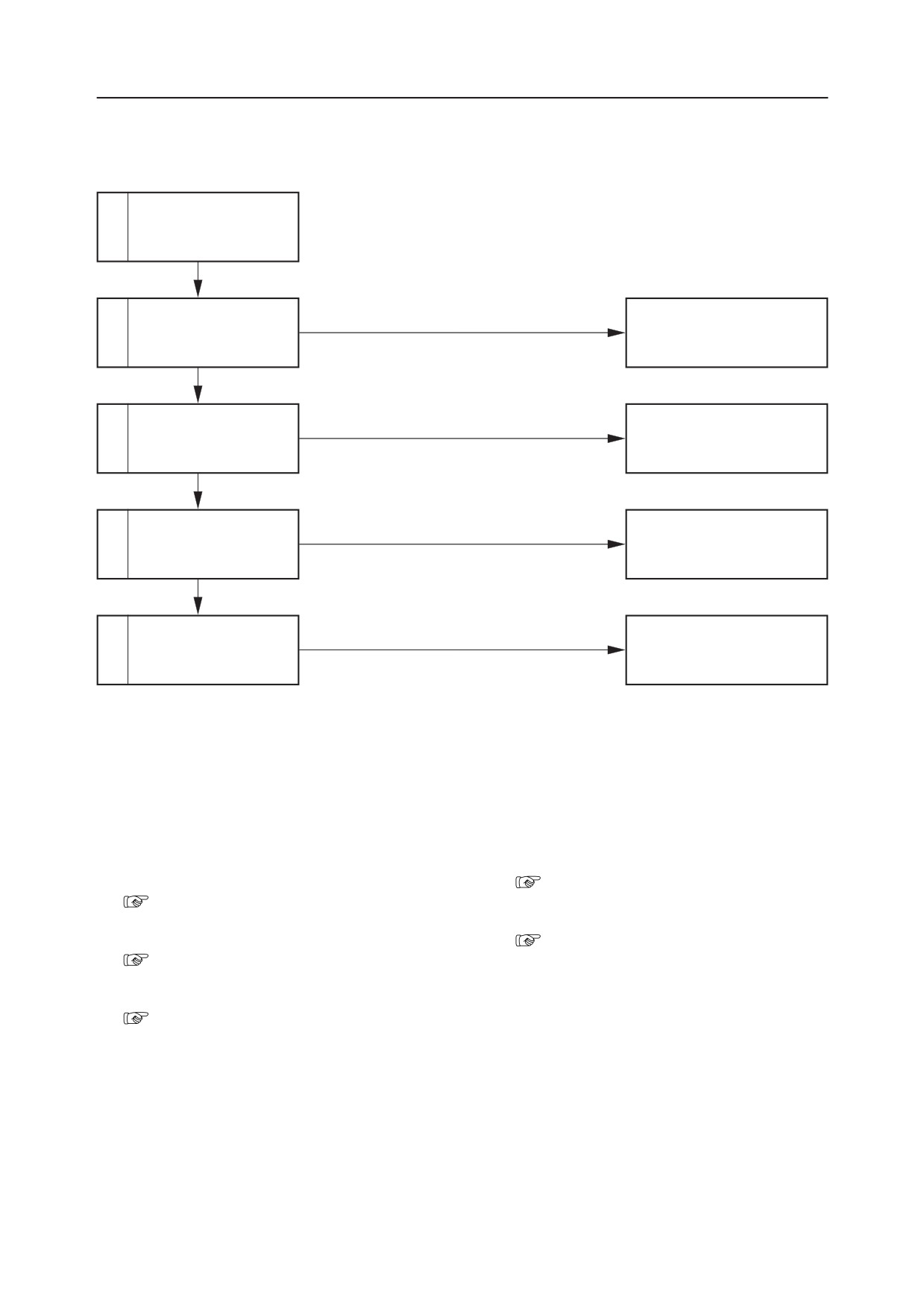
1. Inspect the supply pressure to the pilot valve
4. Inspect the selector valve.
(swing).
“V-28~29”
“V-7~8”
5. Inspect the swing cylinder.
2. Inspect the pilot valve (swing).
“IV. Hydraulic Units, Cylinders”
“V-27”
3. Inspect the operation of the spool.
“V-28”
TB175W
V-38
BOOM SWING
TROUBLESHOOTING
Mono Boom
Inspect the supply pres-
1
sure to the pilot valve
(swing).
Normal
Inspect the pilot valve
Faulty
Repair or replace the pilot
2
(swing).
valve (swing).
Normal
Inspect the operation of
Faulty
Repair or replace the housing
3
the spool.
block.
Normal
Faulty
Repair or replace the check
4
Inspect the check valve.
valve.
Normal
Inspect the swing cylin-
Faulty
Repair or replace the swing
5
der.
cylinder.
1. Inspect the supply pressure to the pilot valve
(swing).
“V-7~8”
2. Inspect the pilot valve (swing).
“V-27”
3. Inspect the operation of the spool.
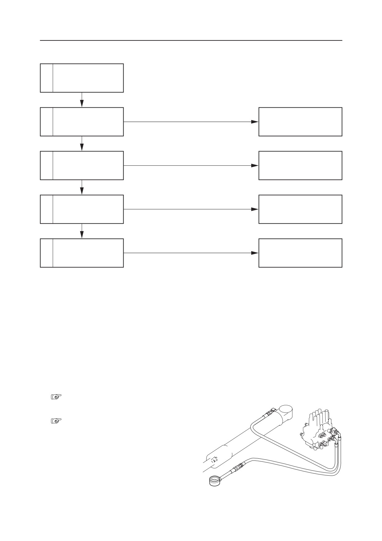
Disconnect the hose between the control valve
(swing section) and the cylinder on the cylinder
side, then set a pressure gauge in the disconnected
hose.
• Operate the boom swing pedal and measure
the pressure.
• A pressure of 27.5 MPa is normal.
V-39
TB175W
TROUBLESHOOTING
BOOM SWING
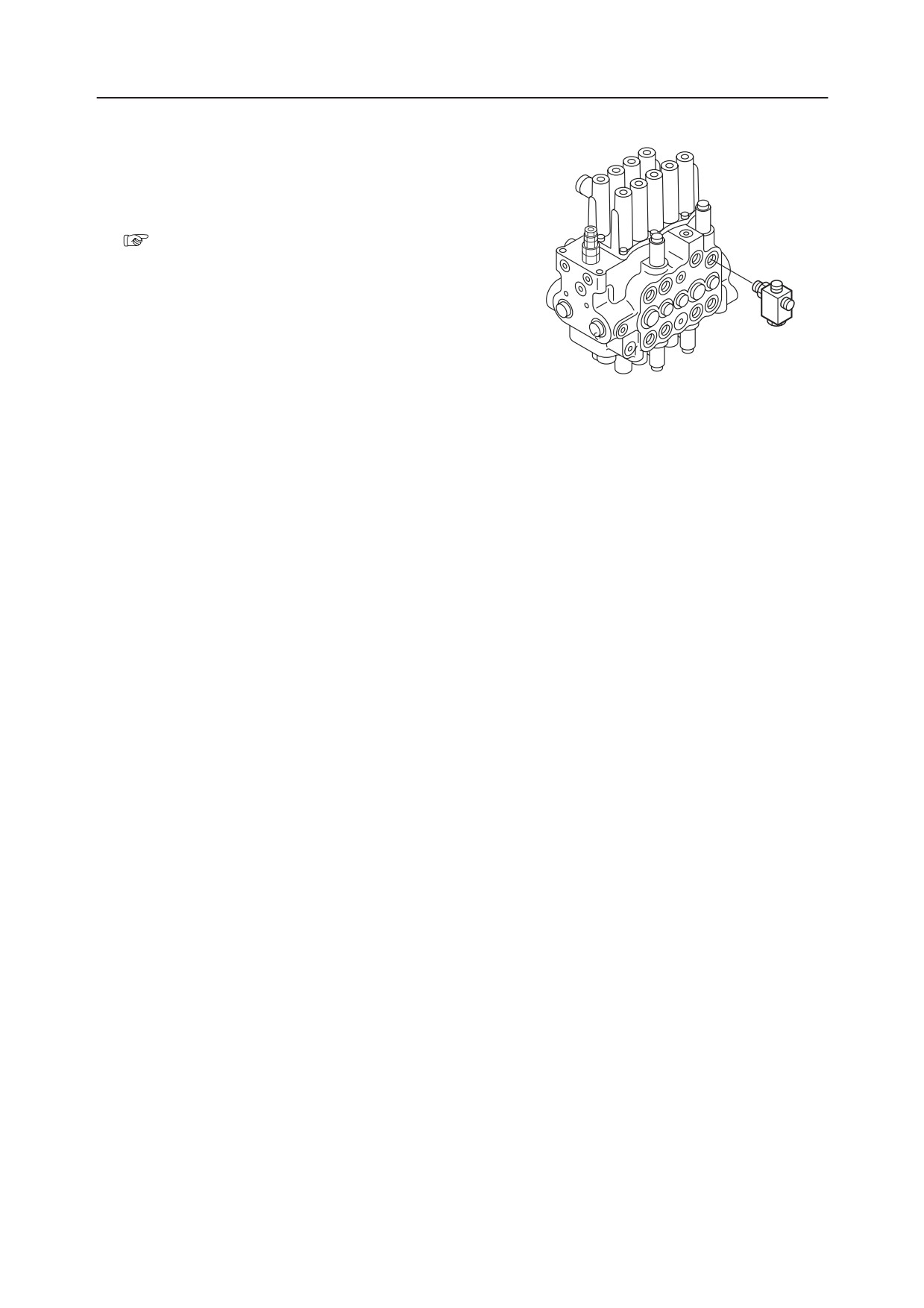
4. Inspect the check valve.
If right swing cannot be done, then foreign matter
is caught in the check valve or the valve is
sticking.
5. Inspect the swing cylinder.
“IV. Hydraulic Units, Cylinders”
W2E013
TB175W
V-40
VI . ENGINE
Machine Serial No.
Mounted Engine
Machine Model
TB175W
17540001~
4TNV98T
TB175W
ENGINE TROUBLE DIAGNOSTICS TOOL AND MAINTENANCE TOOL
1. Introduction
Our maintenance tools are designed to identify the causes of troubles so that machines can be quickly returned to
normal. We also offer a tool to adjust the quantity of oil in the service port for machines with an optional attachment,
to ensure safer maintenance work. These tools are offered only to the designated dealers, and are to be used by main-
tenance technicians with knowledge of computers, so the basic computer operations are not explained.
2. System overview
There are two main tools for maintenance: the engine trouble diagnostic tool provided by the engine manufacturer and
the maintenance tool provided by Takeuchi. Some of our machines have a control computer which can be connected
to a personal computer for communications, allowing computers to read or write data.
(1) Engine trouble diagnostic tool
This tool is used to diagnose troubles with the engine controller of machines with Tier 3-compliant engines and to
flash the engine control data. It can be purchased from the engine manufacturer, Isuzu or Yanmar. Tier 3-compliant
engines are electronically controlled by the Engine Control Unit (ECU) or Engine Control Module (ECM). These
controllers use data specific to Tier 3-compliant and regulation-approved engines, and the trouble diagnostic tool
is specifically designed for them; regular maintenance software for the controller intended for the whole machine
cannot be used.
In case of trouble, the engine trouble diagnostic tool is used to display the error codes and states, from which the
cause of trouble can be identified and action taken according to the engine manufacturerʼs manual.
To purchase the tool, contact our Sales or Parts department.
For details of the tool, read the userʼs manual of the manufacturer.
The maintenance software is permitted to be used only by licensed manufacturers and service dealers.
(2) Maintenance tool and maintenance software
This tool is used to read data from the machine controller and to adjust peripheral devices.
• Reading the error codes stored in the Takeuchi Electrical Control Unit (T-ECU)
Past trouble details can be read or deleted.
∗ For the details of error codes, refer to the manual included in the software CD and the maintenance manual.
• Reading the parameters and writing the modified data in the proportional amplifier for the service port
The proportional output for the first/second auxiliary line can be modified.
The operation speed of various attachments can be modified.
• It is possible to read each serial number and the software version of the controller connected to the device.
The serial number of the controller is necessary for manufacturing management or for troubleshooting.
Machine maintenance tool and trouble analysis tool
Engine manufacturer
Takeuchi maintenance tool
Emission
Develop-
Machine Ser.
maintenance tool
Model
standards
ment code
No.
Software CD
Engine
Name
Kit part No. *1
Description of software
part No.
17830001
or
TB180FR
F14C
later
15830001
or
• T-ECU maintenance soft-
F10C
17301-42800
17301-42700
later
ware
TB153FR
15820001
or
F10B
later
51410001
or
• T-ECU maintenance soft-
TB1140
A25B
later
ware
17301-42810
17301-42660
• Maintenance software for
51430001
or
TB1140
A25D
the proportional amplifier
later
of the service port
22400001
or
TL240
T-3
L8B
Yanmar
EDT
later
22300001
or
TL230
T-3
L6B
Yanmar
EDT
later
22200001
or
TL220
T-3
L5B
Yanmar
EDT
later
17840001
or
• T-ECU maintenance soft-
TB180FR
T-3
F14E
Yanmar
EDT
17301-42820
17301-42690
later
ware
17530001
or
TB175
T-3
A14E
later
• T-ECU maintenance soft-
Yanmar
EDT
17301-42830
17301-42680
17540001
or
ware
TB175W
T-3
A14EW
later
• T-ECU maintenance soft-
ware
• Controller
management
51420001
or
TB1140
T-3
A25C
Isuzu
EMPS-3
17301-42840
17301-42670
software
later
• Maintenance software for
the proportional amplifier
of the service port
• T-ECU maintenance soft-
ware
• Controller
management
A14E
Monitor ma-
TB175
T-3
Isuzu
EMPS-3
17301-42850
17301-42710
software
Isuzu
chines
• Maintenance software for
the proportional amplifier
of the service port
*1 The kit includes the USB cable assembly to be used to connect to the controller. (Part No.: 17301-42720)
T-ECU: Takeuchi-Electrical Control Unit (Takeuchi)
EDT: Engine Diagnostic Tool (Yanmar)
EMPS-3: Engine Module Programming System (Isuzu)
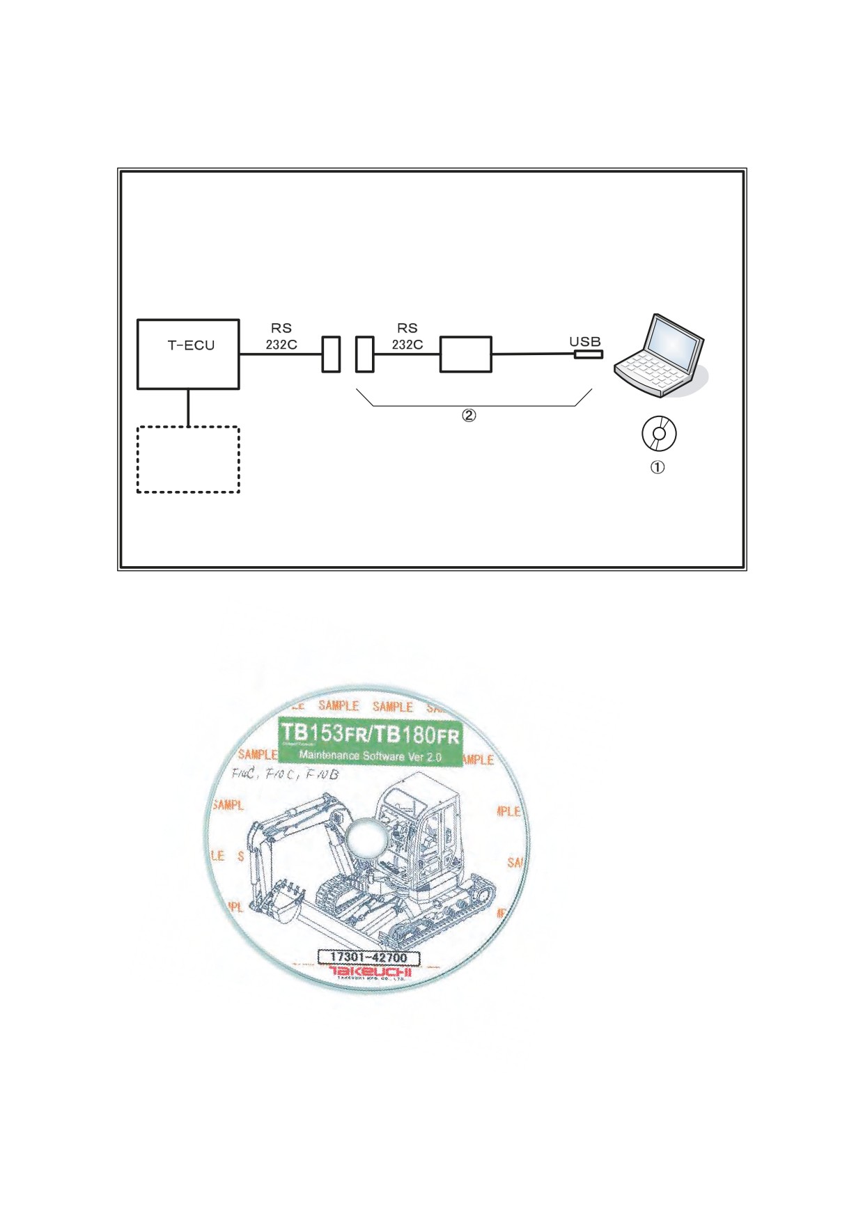
3. Controller connection diagram and system requirements
3.1 Machines with standard engines
(1) Connection diagram for F14C, F10C and F10B
T-ECU: Takeuchi-Electrical Control Unit
Excavator
TB180FR (F14C) T-2
Serial No. 178300001 or later
TB153FR (F10C) T-3
Serial No. 158300001 or later
TB153FR (F10B) T-2
Serial No. 158200001 or later
Laptop computer
Interface box
(Takeuchi)
Engine
Takeuchi maintenance tool
Configuration
ᶃ Maintenance software CD (Part No. 17301-42700)
ᶄ Dedicated USB cable (Part No. 17301-42720)
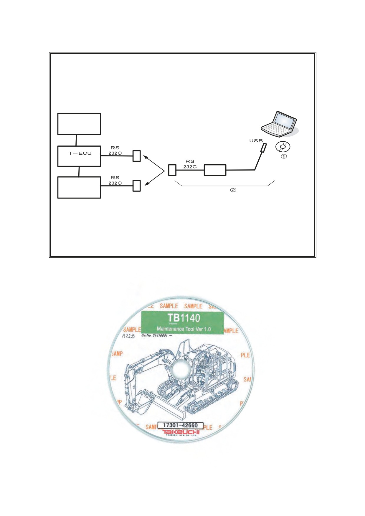
(2) Connection diagram for A25B and A25D
T-ECU: Takeuchi-Electrical Control Unit
Excavator
Engine model: 4BG1TRE (Isuzu)
TB1140 (A25B)
Compliant with Tier 2 emission standards
Serial No. 51410001 or later
TB1140 (A25D)
Serial No. 51430001 or later
Laptop computer
Engine
(Isuzu)
(Takeuchi)
Interface box
Proportional ampli-
fier for the service
Connection
port (Takeuchi)
upon selection
Optional for A25D
Takeuchi maintenance tool
Configuration
ᶃ Maintenance software CD (Part No. 17301-42660)
ᶄ Dedicated USB cable (Part No. 17301-42720)
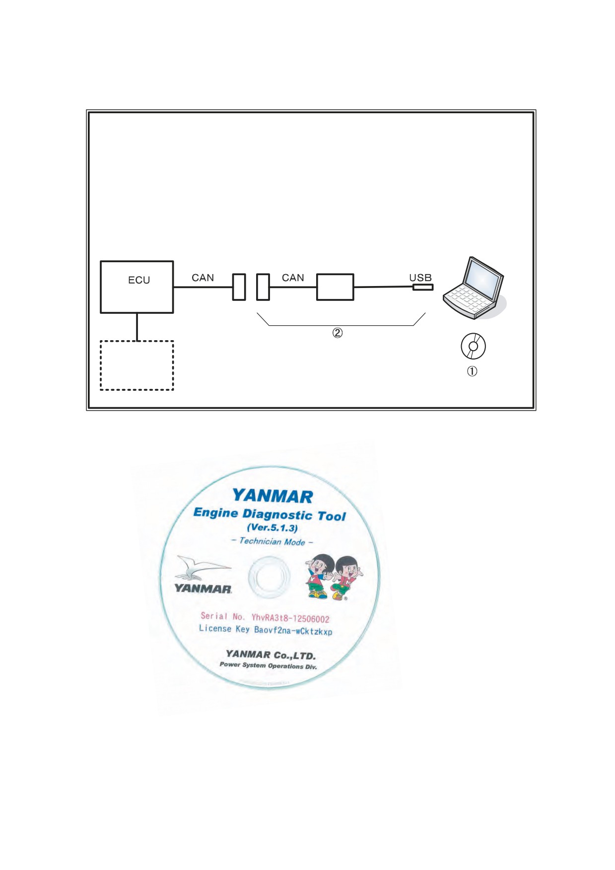
3.2 Machines with standard engines
(1) Connection diagram for TL240, TL230, and TL220
Track loader
Engine model: 4TNV98T-ZNTBL
TL240 (L8B)
Compliant with Tier 3 emission standards
Serial No. 22400001 or later
TL230 (L6B)
Serial No. 22300001 or later
TL220 (L5B)
Serial No. 22200001 or later
Laptop computer
Interface box
(Yanmar)
Yanmar Engine Diagnostic Tool (EDT)
Engine
Configuration
ᶃ Software CD
ᶄ Interface cable