Takeuchi Gear Box 357A10. Service Manual (1998) - page 1
Service Manual
Gear Box
357A10
GSM-0012
January 1998
PRINTED IN ITALY
Vietata la riproduzione anche parziale di testo ed illustrazioni
Realizzazione a cura dell'Ufficio PubblicitaÁ e dell'Ufficio Post Vendita della DANA SPICER CLARK-HURTH
Impaginazione: TEMAS s.r.l. - Gallarate (Va)
Stampa: Gennaio 1998 (N.L. 7309)
Data subject to change without notice. We decline all responsability for the use of non-original components, or accessories which have
not been tested and submitted for approval.
Dati soggetti a modifiche senza impegno di preavviso. Si declina ogni responsabilitaÁ per l'utilizzo di componenti non originali o accessori
non collaudatied apporvati.
Ènderungen ohne vorherige Ank
È ndingung vorbehalten. Es wird jede Verantwortung fuÈr die Verwendung von Nichtoriginalteilen oder
nicht abgenommenem und genehmigtem ZubehoÈr abgelehnt.
Los datos pueden ser modificados sin aviso previo. Se declina toda responsabilidad en el caso de uso de componentes no originales o
bien de accesorios no ensayados y aprobados.
Le constructeur se r
 serve le droit d'apporter des modifications
Á sa production, sans pour cela
à tre tenu d'en donner pre avis. Nous
d
 clinons toute responsabilit
 pour l'utilisation de pi
Á ces non originales ou d'accessoires non test
Âsethomologu
 s.
2
INDEX - INDICE - INHALTSVERZEICHNIS - INDICE - INDEX
GB
INTRODUCTION
4
MAINTENANCE AND LUBRICANT
6
CONVERSION TABLES
7
TIGHTENING TORQUES
7
DIAGRAMS OF REDUCTION UNIT AND EXPLODED VIEWS
8
DISASSEMBLY OF DIRECTLY FLANGED REDUCTION GEAR 357
10
REMOVAL OF HYDRAULIC GEAR CONTROL
12
ASSEMBLY OF DIRECTLY FLANGED REDUCTION GEAR 357
28
INSTALLATION OF HYDRAULIC GEAR CONTROL
44
INTRODUZIONE
4
VORAUSSETZUNG
4
ITA
D
MANUTENZIONE E LUBRIFICANTI
6
WARTUNG UND SCHMIERSTOFFE
6
TABELLE DI CONVERSIONE
7
UMRECHNUNGSTABELLEN
7
COPPIE DI SERRAGGIO
7
ANZIEHDREHMOMENTE
7
SCHEMI RIDUTTORE ED ESPLOSI
8
SCHEMAS F
ÈRUNTERSETZUNGSGETRIEBE
SMONTAGGIO GRUPPO RIDUTTORE 357 AFFLANGIATO
10
UND ZUSAMMENSTELLUNGSZEICHNUNGEN
8
RIMOZIONE COMANDO MARCIA IDRAULICO
12
DIREKT GEFLANSCHTER REDUZIERER 357 ZERLEGEN
10
ASSEMBLAGGIO GRUPPO RIDUTTORE 357 AFFLANGIATO
28
HYDRAULISCHER GANGSCHALTUNG ENFERNEN
12
INSTALLAZIONE COMANDO MARCIA IDRAULICO
44
DIREKT GEFLANSCHTER REDUZIERER 357 MONTIEREN
28
HYDRAULISCHER GANGSCHALTUNG MONTIEREN
44
PROLOGO
4
INTRODUCTION
4
ESP
F
MANTENIMIENTO Y LUBRICANTES
6
ENTRETIEN ET LUBRIFIANTS
6
TABLAS DE CONVERSION
7
TABLEAUX DE CONVERSION
7
PARES DE TORSION
7
COUPLES DE SERRAGE
7
DIAGRAMAS REDUCTOR Y VISTAS PORMENORIZADAS
8
TRACES REDUCTEUR ET EXPLOSIFS
8
DESMONTAJE GRUPO REDUCTOR 357 CON BRIDA
10
DEMONTAGE DU GROUPE REDUCTEUR BRIDE 357
10
REMOCION MANDO MARCHA HIDRAULICO
12
DEPLACEMENT DE LA COMMANDE DE VITESSES
MONTAJE GRUPO REDUCTOR 357 CON BRIDA
28
HYDRAULIQUE
12
MONTAJE MANDO MARCHA HIDRAULICO
44
ASSEMBLAGE DU GROUPE REDUCTEUR BRIDE 357
28
INSTALLATION DE LA COMMANDE DE VITESSES
HYDRAULIQUE
44
3

INTRODUCTION - INTRODUZIONE - VORAUSSETZUNG - PROLOGO - INTRODUCTION
The efficiency and continued operation of mechan-
martelli in plastica o rame, leve appropriate estrattori e chiavi
GB
ical units depend on constant, correct maintenance
specifiche, al fine di facilitare il lavoro salvaguardando nel
and also on efficient repair work, should there be a
contempo le superfici lavorate e la sicurezza degli operatori.
break-down or malfunction. The instructions contained in this
Prima di procedere al disassemblaggio delle parti e scaricare
manual have been based on a complete overhaul of the unit.
l'olio, eÁ opportuno eseguire un'accurata pulizia del ponte,
However, it is up to the mechanic to decide whether or not it is
asportando incrostazioni ed accumuli di grasso.
necessary to assemble only individual components, when
partial repair work is needed. The manual provides a quick
PREMESSA: Tutti gli organi meccanici smontati, devono
and sure guide which, with the use of photographs and
essere accuratamente puliti con prodotti appropriati, quindi
diagrams illustrating the various phases of the operations,
ripristinati o sostituiti nel caso presentino danni, usura,
allows accurate work to be performed.
incrinature, grippaggi, ecc. In particolare, verificare l'integrit
Á
All the information needed for correct disassembly, checks and
di tutte quelle parti in movimento (cuscinetti, ingranaggi, coppia
assembly of each individual component is set out below. In
conica, alberi) e di tenuta (anelli OR, paraolio), soggette a
order to remove the differential unit from the vehicle, the
maggiori sollecitazioni ed usura.
Á consigliabile, comunque, la
manuals provided by the vehicle manufacturer should be
sostituzione degli organi di tenuta ogni qualvolta si proceda alla
consulted. In describing the following operations it is presumed
revisione o riparazione dei componenti. Al momento del
that the unit has already been removed from the vehicle.
montaggio, gli anelli di tenuta devono essere lubrificati sui
bordi di tenuta. Nel caso della coppia conica, la sostituzione di
IMPORTANT: In order to facilitate work and protect both
uno dei suoi ingranaggi comporta anche la sostituzione
working surfaces and operators, it is advisable to use proper
dell'altro. In fase di montaggio sono da rispettare scrupolosa-
equipment such as: trestles or supporting benches, plastic or
mente i giochi, i precarichi e le coppie prescritte.
copper hammers, appropriate levers, extractors and specific
spanners or wrenches.
VALIDIT
Á: Il manuale fornisce le validitaÁ dei gruppi sotto forma
Before going on to disassemble the parts and drain the oil, it is
di matricola. Al fine di una corretta interpretazione, le validit
Á
best to thoroughly clean the unit, removing any encrusted or
sono indicate come:
accumulated grease.
= fino alla matricola
INTRODUCTORY REMARKS: All the disassembled mechan-
ical units should be thoroughly cleaned with appropriate
= dalla matricola
products and restored or replaced if damage, wear, cracking or
seizing have occurred.
Se non sono indicate validitaÁ, le operazioni di smontaggio ed
In particular, thoroughly check the condition of all moving parts
assemblaggio sono comuni a tutte le versioni.
(bearings, gears, crown wheel and pinion, shafts) and sealing
parts (O-rings, oil shields) which are subject to major stress and
MANUTENZIONE E RIPARAZIONE: Al fine di facilitare
wear. In any case, it is advisable to replace the seals every time
interventi sui gruppi ponte differenziali e cambi di velocit
Á la
a component is overhauled or repaired. During assembly, the
SPICER CLARK-HURTH, ha ritenuto opportuno compilare
sealing rings must be lubricated on the sealing edge. In the
queste istruzioni di manutenzione e riparazione. I disegni delle
case of the crown wheel and pinion, replacement of one
attrezzature specifiche eventualmente necessarie per l'esecu-
component requires the replacement of the other one. During
zione di interventi di manutenzione e riparazione possono
assembly, the prescribed pre-loading, backlash and torque of
essere acquistati direttamente presso il costruttore; i ricambi
parts must be maintained.
possono essere ordinati tramite il costruttore della macchina o
direttamente presso la SPICER CLARK-HURTH.
CLASSIFICATION: This manual classifies units according to
part numbers. For a correct interpretation, classification is
indicated as follows:
Die Leistung und Lebensdauer der mechanischen
= up to the part number
D
Teile h
È ngt nicht nur von einer staÈ ndigen und
richtig durchgefuÈ hrten Wartung sondern auch von
= from the part number on
einem sofortigen Eingriff im StoÈ rungsfall ab. Um dieses
Handbuch zu erstellen sind wir von einer allgemeinen
Èber-
When no classification is given, disassembly and assembly
operations are the same for all versions.
pruÈfung der Einheit ausgegangen, doch entscheidet der
Mechaniker ob die einzelnen Teile bei Reparaturen montiert
SPECIFIC EQUIPMENT AND SPARE PARTS: The drawings of
werden muÈ ssen oder nicht. Das Handbuch ist schnell und
all specific tools required for maintenance and repair work can
einfach nachzuschlagen und ermoÈ glicht es anhand der Abbild-
be found at the end of this manual ; spare parts may be ordered
ungen und der Zeichnungen, die die verschiedenen Vorg
È nge
either from the vehicle manufacturer or directly from the
darstellen, gezielt einzugreifen. Nachstehend sind alle Infor-
Service Centers or Authorised Distributors of SPICER
mationen und Hinweise aufgef
È hrt, die zur Zerlegung, PruÈ fung
CLARK-HURTH.
und Montage der Einzelteile noÈ tig sind. Um die Differentia-
lachse des Fahrzeugs abzumontieren, lesen Sie bitte die
Anweisungen in den HandbuÈ chern des Fahrzeugherstellers.
Die nachstehenden Beschreibungen gehen davon aus, daû die
Il rendimento e la continuitaÁ degli organi meccanici
Fahrzeugachse schon abmontiert worden ist.
ITA
dipendono oltre che da una costante e corretta
WICHTIG: Um die Arbeit zu erleichtern und gleichzeitig die
manutenzione, anche dal tempestivo intervento,
verarbeiteten Fl
È chen zu schuÈ tzen und die Sicherheit der
nell'eventualitaÁ di guasti o anomalie.
Arbeiter zu gewaÈ hrleisten, empfehlen wir geeignete Werk-
Nel proporre questo manuale si eÁ considerata l'ipotesi di una
zeuge wie BoÈ cke, Tisch, Gummi- oder Kupferhammer, geeig-
revisione generale del gruppo ma eÁ il meccanico a valutare la
nete Auszieher und SchluÈ ssel zu verwenden.
necessitaÁ di montare solo i singoli componenti nel caso di
Bevor mit der Zerlegung der Teile begonnen und das
Èl
riparazione. Il manuale eÁ una guida rapida e sicura che
abgelassen wird, muû die Achse sorgfaÈ ltig gereinigt und
consente interventi precisi, tramite le fotografie ed i disegni
Verkrustungen und Fettablagen abgetragen werden.
prospettici che illustrano le varie fasi delle operazioni. Di
seguito sono riportate tutte quelle informazioni ed avvertenze
VORAUSSETZUNG: Alle abmontierten mechanischen Teile
necessarie al corretto disassemblaggio, alle relative verifiche
m
È ssen sorgfaÈ ltig mit geeigneten Reinigungsmitteln gereinigt
ed all'assemblaggio dei singoli componenti. Per la rimozione
oder, wenn beschaÈ digt, verschleiût, gerissen, festgefressen
del ponte differenziale dal veicolo, eÁ necessario consultare i
usw. ausgewechselt werden. Insbesondere muû der einwand-
manuali forniti dal costruttore del veicolo. Nel descrivere le
freie Zustand aller beweglichen Teile
(Lager, ZahnraÈ der,
operazioni seguenti, si presuppone che il ponte sia giaÁ stato
Kegelradpaare, Wellen) und der Dichtungen (O-Ringe,
È lab-
rimosso dal veicolo.
dichtungen), die am meisten beansprucht werden und ver-
schleiûen, kontrolliert werden. Wir empfehlen auf jeden Fall die
IMPORTANTE: In tutte le operazioni, eÁ consigliabile usare
Èber-
Abdichtungselemente immer auszuwechseln, wenn eine
attrezzature idonee quali cavalletti o banchi di sostegno,
holung oder eine Reparatur der Teile vorgenommen wird. Bei
4

der Montage m
È ssen die RaÈ nder der Dichtringe geschmiert
Si no ha sido indicada validez, las operacioÂn de desmontaje y
werden. Wenn beim Kegelradpaar ein Zahnrad ausgewechselt
montaje son comunes a todas las versiones.
werden muû, muû auch das andere Zahnrad ausgewechselt
werden. Bei der Montage muÈ ssen die vorgeschriebenen
HERRAMIENTAS ESPECIFICAS Y RECAMBIOS: Los planos
Spiele, Vorspannungen und Drehmomente strengstens ein-
de las herramientas especificas necesarias para la ejecuci
Ân
gehalten werden.
de las intervenciones de mantenimiento figuran al final del
manual; los recambios se pueden pedir al fabricante de la
G
ÈLTIGKEIT:DasHandbuchgibtanzuwelchenKennummern
ma quina o directamente al Service Center o a Distribuidores
die Einheiten gehoÈren. Der Einfachheit halber sind die
autorizados de SPICER CLARK-HURTH.
Angeh
È rigkeiten folgendermaûen aufgefuÈ hrt:
= bis Kennummer
Le rendement et la continuit
 des organes m
 ca-
= ab Kennummer
F
niques de pendent, non seulement d'une mainte-
Wenn keine AngehoÈ rigkeit angegeben ist, verstehen sich die
nance correcte et constante, mais e galement de la
Arbeiten zur Zerlegung und Montage f
Èr alle AusfuÈ hrungen
rapidite d'intervention en cas de pannes ou d'anomalies. En
guÈ ltig.
vous proposant ce manuel, on envisage l'hypotheÁ se d'une
r
Âvision g
 n
Ârale du groupe, mais c'est au m
Âcanicien
SPEZIFISCHE WERKZEUGE UND ERSATZTEILE: die Zeich-
d'
Âvaluer la n
Âcessite de monter ou non chacun des
nungen der fuÈr Wartungsarbeiten erforderlichen spezifischen
composants en cas de re paration. Le manuel est un guide
Werkzeuge, sind am Ende des Handbuchs aufgefuÈ hrt; Ersatz-
rapide et s
Ãrconsentantdesinterventionspre cises, au travers
teile koÈ nnen beim Fahrzeughersteller oder direkt bei der
de photographies et de dessins prospectifs qui illustrent les
Kundendienststelle oder bei einem zugelassenen HaÈ ndler der
diff
 rentes phases des op
 rations. Ensuite, sont report
 es
toutes les informations et pr
 cautions ne cessaires pour un
SPICER CLARK-HURTH bezogen werden.
d
 montage correct et les ve rifications et assemblage de
chaque composant. En ce qui concerne le de placement du
pont d'
 tai du v
 hicule, il est ne cessaire consulter les manuels
fournis par le constructeur du v
 hicule. En de crivant les
El rendimiento y la duraci
Ân de los oÂrganos
op
 rations suivantes, on pr
 sume que le pont ait d
 j
Á
 t
Â
ESP
mec
 nicos depende, ademaÂs que del constante y
enlev
 du ve hicule.
correcto mantenimiento, tambieÂn de la interven-
cioÂn inmediata en caso de averÂas o anomalÂas.
IMPORTANT: Pour faciliter le travail en sauvegardant en
Al proponer este manual, ha sido considerada la suposici
Ân de
m
à me temps les surfaces usin
 es et la s
 curit
 des op
 ra-
una revisi
Ângeneraldelgrupo,peroeselmeca nico quien tiene
teurs, il est pr
 conis
 d'utiliser des installations appropri
 es
que valorar la necesidad de montar cada uno de los
telles que des e tais ou banc de support, maillets en plastique
componentes en caso de reparacio n. El manual es una guÂa
ou cuivre, leviers appropri
 s, extracteurs et cl
Âsspe cifiques.
ra pida y segura que permite intervenciones precisas por medio
Avant de proc
 der au de montage des parties et vidanger
de fotografÂas y de planos que muestran las distintas fases de
l'huile, il vaut mieux nettoyer soigneusement le pont, en
las operaciones. A continuacioÂn figuran todas las informacio-
enlevant incrustations et blocs de gras.
nes y advertencias necesarias para ejecutar un montaje
correcto, para las comprobaciones y el montaje de cada uno
PRELIMINAIRE: Tous les organes m
 caniques d
 mont
Âs
de los componentes. Para remover el puente diferencial del
doivent
à tre soigneusement nettoy
Âs aÁ l'aide de produits
vehÂculo hay que consultar los manuales de los fabricantes del
appropri
Âsetr
 par
Âsouremplac
ÂsdanslecasouÁ ils seraient
vehÂculo. En la descripcioÂn de las operaciones siguientes se
abÃm
 s, us
 s, f
Ãl
 s, gripp
 s, etc. V
Ârifier, l'int
 grit
Â, en
supone que el puente ya ha sido sacado del vahÂculo.
particulier, de toutes les parties en mouvement
(paliers,
engrenages, couple conique, arbres) et l'
Âtanch
Âit
 des
IMPORTANTE: Para facilitar el trabajo salvaguardando al
bagues (bagues OR, parahuile), qui sont sujettes aÁ plus de
mismo tiempo las superficies mecanizadas y la seguridad de
sollicitations et
Á l'usure. Il est pr
 conis
Â, de toute facËon, de
los operadores, se aconseja que se usen equipos y herra-
substituer les organes d'
 tanch
 iteÂ, chaque fois que l'on
mientas adecuados como caballetes y bancos de soporte,
effectue une r
 vision ou une re paration des composants. Au
martillos de plaÂstico o de cobre, palancas adecuadas,
moment du montage, les bagues d'
 tanch
 it
 doivent
à tre
extractores y llaves especÂficas.
lubrifi
 es sur les bords e tanches. Dans le cas du couple
Antes de desmontar las partes y descargar el aceite, es
conique, la substitution de l'un de ses engrenages comporte
conveniente que se haga una limpieza minuciosa del puente
e galement la substitution de l'autre. En phase de montage, il
sacando las incrustaciones y acumulaciones de grasa.
faut respecter scrupuleusement les jeux, les pre charges et les
couples prescrits.
INTRODUCCION: Todos los
 rganos meca nicos desmontados
tienen que ser limpiados minuciosamente con productos
VALIDITE: Le manuel fournit la validite des groupes sous
adecuados y restaurados o sustituidos en el caso de que
forme de matricule. Pour une meilleure interpre tation, les
presenten danÄ os, desgaste, rajaduras, agarrotamientos, etc.
validit
Âssontindique es comme:
En particular, comprobar la integridad de todas las partes en
movimiento (cojinetes, engranajes, par co nico, ejes) y de
= jusqu'aÁ l'immatriculation
estanqueidad (anillos OR, detenedor de aceite) sujetas a
mayores solicitaciones y desgaste.
=
Á partir de l'immatriculation et apr
Ás
Se aconseja, de todas formas, que se sustituyan los o rganos
de estanqueidad cada vez que se ejecute la revisi
Ân o
Si les validit
Âs ne sont pas indiqu
 es, les ope rations de
reparacioÂn de los componentes.
de montage et d'assemblage sont pareilles dans toutes les
Al volver a montar, los segmentos de compresioÂn tienen que
versions.
estar lubricados en los bordes de estanqueidad. En el caso del
par c
 nico, la sustitucioÂn de uno de sus engranajes comporta
INSTALLATIONS SPECIFIQUES ET PIECES DETACHEES:
tambi
Ân la sustitucioÂn del otro. Al montar hay que tener en
Les dessins des installations sp
 cifiques ne cessaires pour
cuenta escrupulosamente los juegos, las precargas y los pares
effectuer des interventions d'entretien sont report
 es aÁ la fin du
descriptos.
manuel, les pi
Á ces d
 tach
 es peuvent
à tre commande es au
constructeur de la machine ou directement aux Centres de
VALIDEZ: El manual suministra la validez de los grupos en
Services, ou Distributeurs agr
Â
Âs de la Soci
 te SPICER
forma de matrÂcula. Para poder tener una interpretaci
Ân
CLARK-HURTH.
correcta, la validez esta indicada:
= hasta la matrÂcula
= desde la matrÂcula en adelante
5
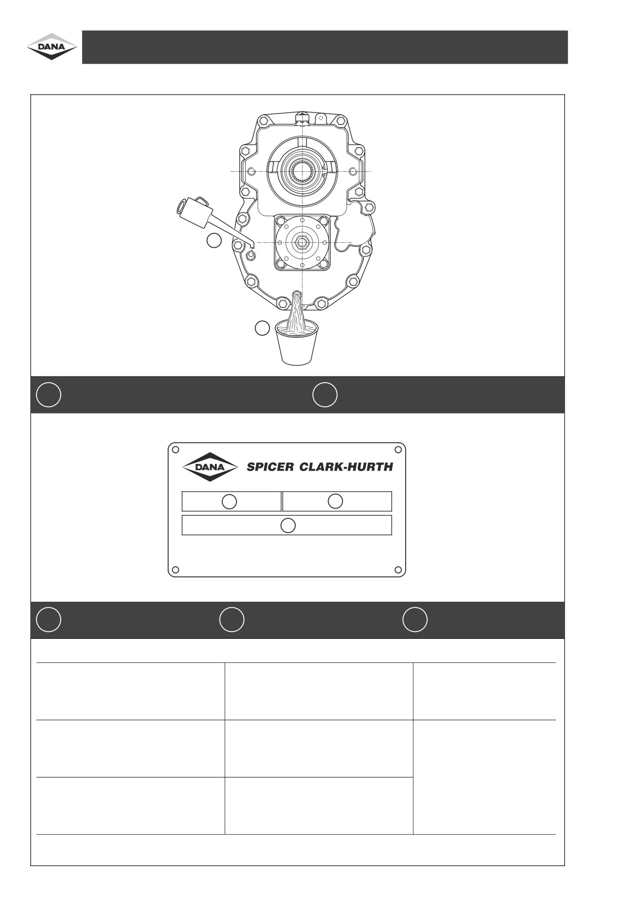
MAINTENANCE AND LUBRICANT - MANUTENZIONE E LUBRIFICANTI - WARTUNG UND SCHMIERSTOFFE
MANTENIMIENTO Y LUBRICANTES - ENTRETIEN ET LUBRIFIANTS
1
2
D1240009
Oil fill and level plug
Oil drain plug
Tappo carico e livello olio
Tappo scarico olio
È leinf
Èll- und
È lstandschraube
È leinf
Èll- und
È lablaûschraube
1
TapoÂn de relleno y nivel aceite
2
TapoÂn de vaciado nivel aceite
Bouchon de remplissage et jauge d'huile
Bouchon de vidage huile
1
2
3
MFG. BY CLARK-HURTH COMPONENTS S.P.A.
38062 Arco (Trento)
MADE IN ITALY
D1240011
Type and model unit
Serial number
Lubrificant
Tipo e modello gruppo
Numero di serie
Lubrificante
Type und modell Antriebes
Seriennummer
Schmieroel
1
Tipo y modelo unidad
2
NuÂmero de serie
3
Lubricante
Type et modeÂle de ensemble
Numero de serie
Lubrificant
OPERATION
FREQUENCY
LUBRICANTS
OPERAZIONE
PERIODICIT
Á
LUBRIFICANTI
ARBEITSVORGANG
ZEITABSTAND
SCHMIERSTOFFE
OPERACION
FRECUENCIA
LUBRICANTES
OPERATION
PERIODICITE
LUBRIFIANTS
. Check levels:
monthly
. Controllo livelli:
mensile
.
È lstandkontrolle:
monatlich
Control niveles:
cada mes
. Controà le niveaux:
mensuel
SAE85W90 API GL3
. Oil change:
every 1000 hours ]
. Cambio olio:
ogni 1000 ore
.
È lwechsel:
alle 1000 Std.
Cambio aceite:
cada 1000 horas
. Vidange huile:
toutes les 1000 hours
] Initially after 100 working hours - Inizialmente dopo 100 ore di lavoro - Erstmals nach 100 Betriebstunden - Al principio, despu
Âs de
100 horas de trabajo - Initialement apr
Ás100heuresdetravail
6
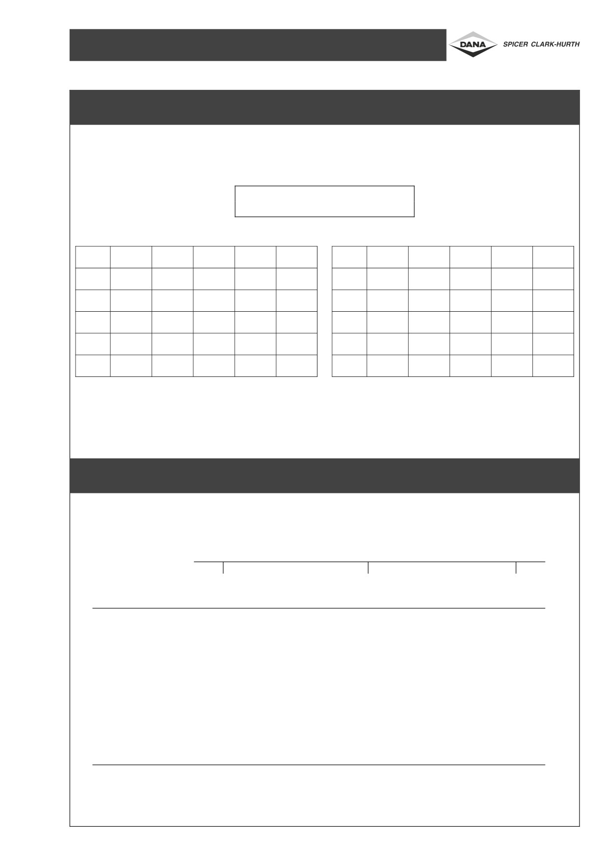
CONVERSION TABLES - TABELLE DI CONVERSIONE - UMRECHNUNGSTABELLEN
TABLAS DE CONVERSION - TABLEAUX DE CONVERSION
1 Atm%1 bar%105 PA%14.4 PSi
Pa
N
daN
kN
kg
lbs
Nm
daNm
kNm
kgm
lb-in
1N
1
0,1
0,001
0,102
0,225
1Nm
1
0,1
0,001
0,102
8,854
1daN
10
1
0,01
1,02
2,25
1daNm
10
1
0,01
1,02
88,54
1kN
1000
100
1
102
225
1kNm
1000
100
1
102
8854
1kg
9,81
0,981
0,00981
1
2,205
1kgm
9,81
0,981
0,00981
1
86,8
1lb-in
0,1129
0,01129
0,0001129
0,01152
1
TIGHTENING TORQUES - COPPIE DI SERRAGGIO - ANZIEHDREHMOMENTE
PARES DE TORSION - COUPLES DE SERRAGE
TYPE OF BOLT - TIPO VITE - GEWINDE - TIPO DE TORNILLO - TYPE DE VIS
SIZE OF BOLT
MISURA VITE
SCHRAUBENMASS
8G/8,8
10k/10,9
12k/10,9
TAMA
ÄO TORNILLO
MESURE VIS
Nm
Nm
Nm
M4
2,9
4,1
Ð
M6
10,0
14,0
Ð
M8
25,0
35,0
Ð
M10
49,0
69,0
Ð
M10x1,25
52,0
73,0
88,0
M12
86,0
120,0
Ð
M14
135,0
190,0
Ð
M14x1,5
150,0
210,0
250,0
M16
210,0
295,0
Ð
M18x1,5
325,0
460,0
550,0
A22
550
7
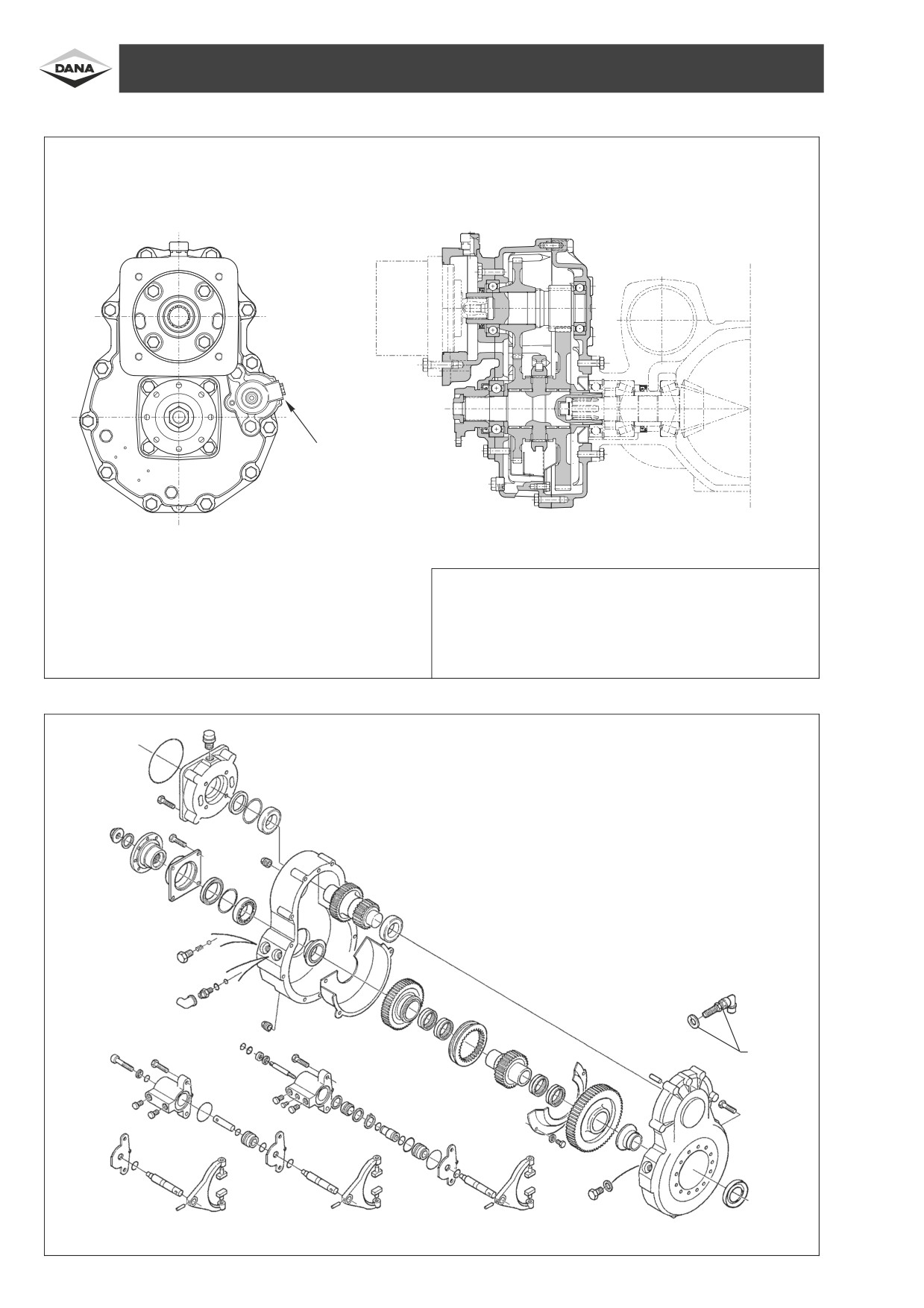
DIAGRAMS OF REDUCTION UNIT AND EXPLODED VIEWS - SCHEMI RIDUTTORE ED ESPLOSI - SCHEMAS F
ÈRUNTERSETZUNGSGETRIEBE
UND ZUSAMMENSTELLUNGSZEICHNUNGEN - DIAGRAMAS REDUCTOR Y VISTAS PORMENORIZADAS - TRACES REDUCTEUR ET EXPLOSIFS
DIAGRAM
SCHEMA
SCHEMAS
DIAGRAMAS
TRACES
A
D1240001
TECHNICAL DATA - CARATTERISTICHE TECNICHE - TECHNISCHE DATEN - CARACTERI-
STICAS TECNICAS - CARACTERISTIQUES TECHNIQUES
A - Connector for hydraulic gear control - Pressure required 15±30 bar
Raccordi comando marce idraulico - Pressione di comando 15±30 bar
Anschluss f
ÈrhydraulischerBetaÈtigung der Gangschaltung Schaltdruck 15±30 bar
Conexi
Ânmandomarchahydraulico-PresioÂn de mando 15±30 bar
Raccord commande des vitesses hydraulique - Pression de commande 15±30 bar
REDUCTION GEAR
RIDUTTORE
UNTERSETZUNGSGETRIEBE
REDUCTOR
REDUCTEUR
]
D1240012
] OPTIONAL
8
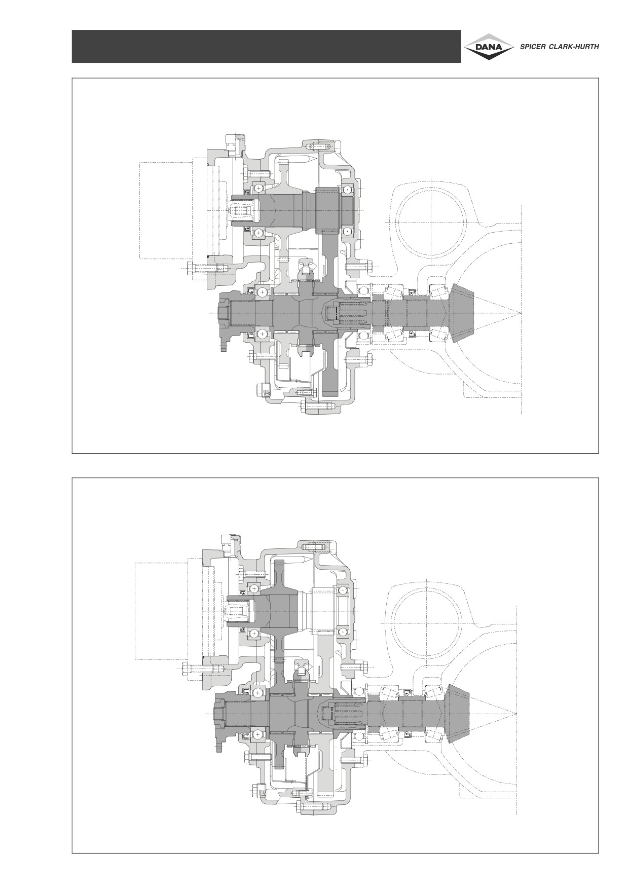
Ist GEAR
Ië MARCIA
Ië GANG
Ië MARCHA
Ië VITESSE
D1240002
IInd GEAR
IIë MARCIA
IIë GANG
IIë MARCHA
IIë VITESSE
D1240003
9
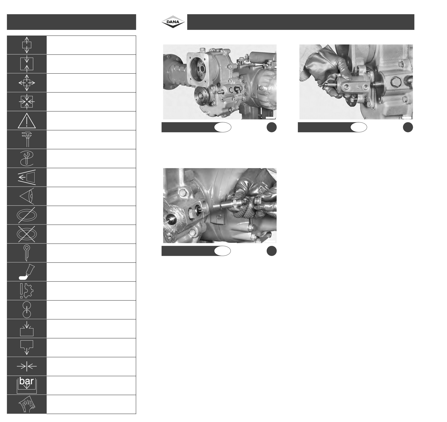
SYMBOLS - SIMBOLI - SYMBOLS
DISASSEMBLY OF DIRECTLY FLANGED REDUCTION GEAR 357- SMONTAGGIO GRUPPO RIDUTTORE 357 AFFLANGIATO - DIREKT GEFLANSCHTER
SIMBOLOS - SYMBOLES
REDUZIERER 357 ZERLEGEN - DESMONTAJE GRUPO REDUCTOR 357 CON BRIDA - DEMONTAGE DU GROUPE REDUCTEUR BRIDE 357
Disassembly of assembly groups
Smontaggio di sottogruppi
Zerlegen von Baugruppen
Desmontaje de subgrupos
Demontage des sous-groupes
Reassemble to from assembly groups
Montaggio di sottogruppi
Zusasmmenbauen von Baugruppen
Ensamblaje de subgrupos
Montage des sous-groupes
Remove obstruction parts
Smontaggio di particolari ingombri
Abbauen-Ausbauen
Desmontaje de componentes abultados
Demontage des pieces encombrante
Reinstall-remount parts which had obstructed disassembly
Montaggio di particolari ingombri
Einbauen-Ausbauen
Montaje de componentes abultados
Montage des pieces encombrante
Attention ! Important notice
Attenzione, indicazione importante
F1240069
F1240070
Achtung, wichtiger Hinweis
¡ Cuidado ! IndicacioÂn importante
Attention, indication importante
GB
a
GB
b
Check - adjust e.g. torque, dimensions, pressures, etc.
Controllare - regolare p.e. coppie, misure, pressioni ecc.
Reduction gear directly flanged on the axle with mechanic gear
Reduction gear directly flanged on the axle with hydraulic gear
PruÈ fen - Einstellen z.B. Momente, Maûe, Drucke u.s.cs.
control.
control.
Controlar y ajustar, por ej. pares, medidas, presiones, etc.
Controler, regler p.e. couples, mesures, pressions ecc.
T=Special tool
P=page
T=Attrezzature speciali
P=Pagina
T=Spezialwerkzeug
P=Seite
T=Herramientas especiales
P=P
Âgina
T=Outils
P=Page
Note direction of installation
Rispettare direzione di montaggio
Einbaurichtung beachten
Respetar la direccioÂn de ensamblaje
Respecter direction de montage
Visual inspection
Esaminare con controllo visuale
Kontrollieren -Pr
Èfen
Examinar mediante inspeccioÂn visual
Controler, examiner, controle visuel
Possibly still serviceable, renew if necessary
Eventualmente riutilizzare (sostituire se necessario)
Bedingt weiderverwendbar
Puede volver a utilizarse (reemplazar, si es preciso)
Eventuellement a utiliser a noveau (remplacer si neÂcessaire)
Renew at each reassembly
Sostituire con ogni montaggio
Beim Zusammenbau immer erneuern
Puede reemplazarse a cada ensamblaje
Remplacer avec chaque montage
F1240071
Unlock - lock e.g. split pin, locking plate, etc.
Togliere-mettere la sicura
GB
c
Entsichern-Sichern
Quitar-colocar el seguro
Enlever-mettre la securite
Reduction
gear directly
flanged on
the
axle
with
or
without
Lock-adhere (liquid sealant)
revolution indicator.
Mettere la sicura, incollare (mastice liquido)
Sichern-Kleben (fluÈssige Dichtung)
Colocar el seguro, pegar (mastique lÂquido)
Mettre la securite, coller (mastic liquide)
Guard against material damage, damage to parts
Evitare danni materiali, danni a pezzi
Materialschaden verh
È ten
Evitar danÄar los materials o las piezas
Eviter dommages au materiaux, dommages au pieces
Mark before disassembly, observe marks when reassembly
Marchiare prima dello smontaggio (per il montaggio)
Vor dem Ausbau markieren (fuÈr den Zusammenbau)
Marcar antes de desmontar (para facilitar el ensamblaje)
Marquer avant le demontage (pour le montage)
Filling - topping up - refilling e.g. oil, cooling water, etc.
Caricare - riempire (olio - lubrificante)
Einf
Èllen - Auff
È llen - Nachf
Èllen
(
È l-Schmiermittel)
Cargar - llenar (aceite lubricante)
Charger - remplir (huile - lubrifiant)
Drain off oil, lubricant
Scaricare olio, lubrificante
È l, bzw. Schmiermittel Ablassen
Descargar aceite lubricante
Vidanger, lubrifiant
Tighten
Tendere
Spannen
Tensar
Tendre
Apply pressure into hydraulic circuit
Inserire pressione nel circuito idraulico
Leitung unter Druck setzen
Introducir presi
ÂnenelcircuitohidraÂulico
Inserer pression dans le circuit hydraulique
To clean
Pulire
Reinigen
Limpiar
Nettoyer
10

Versione afflangiata al ponte con comando marcia
Versione afflangiata al ponte con comando marcia
ITA
ITA
meccanico.
idraulico.
Direkt an der Triebachse geflanscht mit mechanischer
Direkt an der Triebachse geflanscht mit hydraulischer
D
D
Gangschaltung.
Gangschaltung.
a
b
Versi
Ânconbridaenel puenteconmandomeca nico
Versi
Ânconbridaenelpuenteconmandohidra ulico
ESP
ESP
de la marcha.
de la marcha.
Mod
Ále brid
 au pont aÁ commande de vitesses
Mod
Ále brid
 au pont aÁ commande de vitesses
F
F
me canique.
hydraulique.
Versione afflangiata al ponte con o senza rilevatore di
ITA
giri.
Direkt an der Triebachse geflanscht mit oder ohne
D
Drehzahlmesser.
c
VersioÂn con brida en el puente con o sin detector de
ESP
revoluciones.
Mod
Á le bride pont avec ou sans compteur de tours.
F
11
REMOVAL OF HYDRAULIC GEAR CONTROL - RIMOZIONE COMANDO IDRAULICO - HYDRAULISCHER GANGSCHALTUNG ENFERNEN -
REMOCION MANDO MARCHA HIDRAULICO - DEPLACEMENT DE LA COMMANDE DE VITESSES HYDRAULIQUE
F1240072
F1240073
GB
a
GB
b
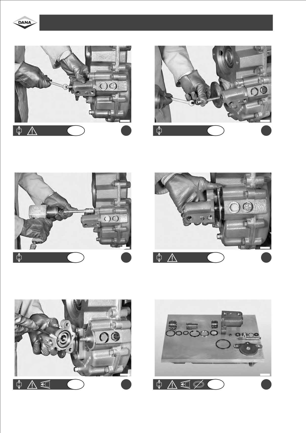
Remove the gear control rod.
Pull out the control rod.
F1240074
F1240075
GB
c
GB
d
Remove screws on the gear control cylinder.
Remove the gear control cylinder.
F1240076
F1240077
GB
e
GB
f
Pull out the gear control cylinder.
Re-assembly arrangement of gear control cylinder parts.
Pay attention to the position of the O-rings. Remove the protection
plate.
12

Rimuovere l'asta di comando marce.
Estrarre l'asta comando.
ITA
ITA
Gangschalterhebel abnehmen.
Hebel herausziehen.
D
D
a
b
Remover la varilla de mando de las marchas.
Extraer la varilla de mando.
ESP
ESP
Enlever la tringle de commande de vitesses.
Extraire la tringle de commande.
F
F
Rimuovere le viti del cilindro comando marce.
Rimuovere il cilindro comando marce.
ITA
ITA
Die Schrauben vom Zylinder des Gangschalters
Zylinder des Gangschalters abnehmen.
D
D
abnehmen.
c
d
Remover los tornillos del cilindro de mando de las
Remover el cilindro de mando de las marchas.
ESP
ESP
marchas.
Enlever les vis du cylindre de commande de vitesses.
Enlever le cylindre de commande de vitesses.
F
F
Estrarre il cilindro comando marce.
Ordine di rimontaggio dei particolari del cilindro di
ITA
ITA
Prestare attenzione alla posizione degli anelli OR.
comando marce.
Rimuovere la lamiera di protezione.
Zylinder des Gangschalters herausziehen.
Reihenfolge zur Montage der Einzelteile des Gangs-
D
D
Auf die Position der O-Ringe achten. Schutzblech
chalterzylinders.
abnehmen.
e
f
Extraer le cilindro de mando de las marchas.
Orden para volver a montar las piezas del cilindro de
ESP
ESP
Tener cuidado con la posicioÂn de los anillos OR.
mando de las marchas.
Remover la placa de protecci
 n.
Extraire le cylindre de commande de vitesses
Placer les pieÁ ces en ordre en vue du remontage du
F
F
Faire attention au positionnement des bagues OR
cylindre de commande de vitesses.
Enlever la toà le de protection.
13
DISASSEMBLY OF DIRECTLY FLANGED REDUCTION GEAR 357- SMONTAGGIOGRUPPORIDUTTORE 357 AFFLANGIATO- DIREKT GEFLANSCHTER
REDUZIERER 357 ZERLEGEN - DESMONTAJE GRUPO REDUCTOR 357 CON BRIDA - DEMONTAGE DU GROUPE REDUCTEUR BRIDE 357
F1240078
F1240079
GB
a
GB
b
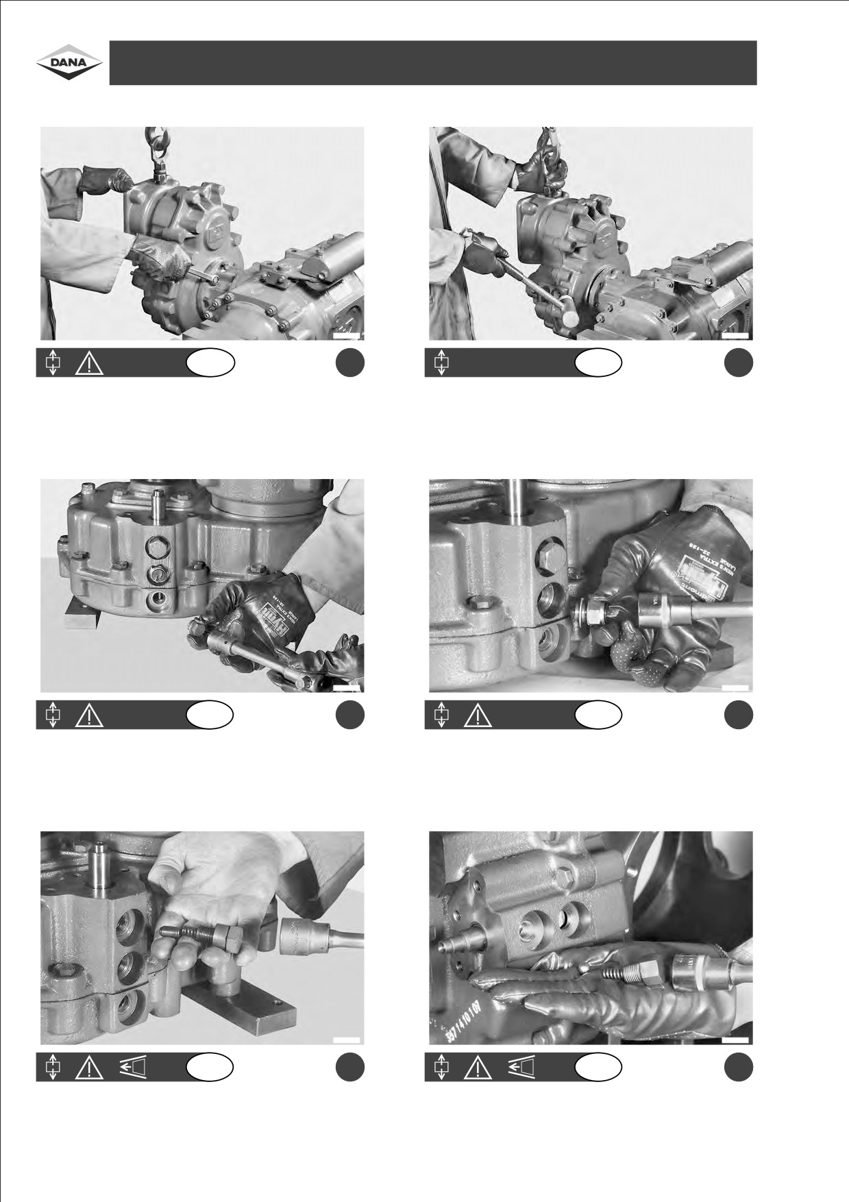
Remove fastening screws from the reduction unit.
Disjoin the entire reduction unit from the axle and place it on a
bench.
F1240080
F1240081
GB
c
GB
d
Remove the sealing cover with the relative washer or the revolution
Remove gear-in position switch, O-ring and washer.
indicator.
F1240082
F1240083
GB
e
GB
f
Remove screw, spring, together with gear-and-neutral position
Remove screw, spring and neutral position ball (hydraulic version).
spindle (mechanical version).
14

Rimuovere le viti di fissaggio del riduttore.
Staccare il riduttore completo dal ponte e posizionarlo
ITA
ITA
su un banco.
Reduziererbefestigungsschrauben abschrauben.
Den gesamten Reduzierer von der Triebachse neh-
D
D
men und einen Tisch legen.
a
b
Remover los tornillos de fijacioÂn de reductor.
Desprender el reductor completo del puente y posi-
ESP
ESP
cionarlo en un banco.
Enlever les vis de fixation du re ducteur.
D
 tacher le re ducteur tout entier du pont et le mettre
F
F
sur le banc.
Rimuovere il tappo di chiusura con rosetta oppure il
Rimuovere l'interruttore di posizione marcia inserita
ITA
ITA
rilevatore di giri.
con anello OR e rosetta.
Stopfen mit Unterlegscheibe oder Drehzahlmesser
Schalter fuÈr die Position der Gangschaltung mit O-
D
D
entfernen.
Ring und Unterlegscheibe entfernen.
c
d
Remover el tapoÂn de cierre con la roseta o bien el
Remover el interruptor de posicioÂn de marcha em-
ESP
ESP
detector de revoluciones.
bragada con el anillo OR y la roseta.
Enlever le bouchon de verrouillage aÁ rondelle ou bien
Enlever l'interrupteur de la position vitesses incorpor
Â
F
F
le compteur de tours.
avec la bague OR et la rondelle.
Rimuovere la vite, la molla ed il puntalino di posizione
Rimuovere la vite, la molla e la sfera di posizone folle
ITA
ITA
marcia e folle (versione meccanica).
(versione idraulica).
Schraube, Feder und Stift fuÈr die Position der Gangs-
Schraube, Feder und Kugel fuÈr die Position des
D
D
chaltung und des Leerlaufs entfernen (mechanische
Leerlaufs entfernen (hydraulische AusfuÈ hrung).
AusfuÈ hrung).
e
f
Remover el tornillo, el muelle y el pasador de posici
Ân
Remover el tornillo, el muelle y la bola de posici
Ân de
ESP
ESP
de marcha y punto neutro (versi
Ânmeca nica).
punto neutro (versi
Ânhidra ulica).
Enlever la vis, le ressort et la buteÂe de position
Enlever la vis, le ressort et la spheÁ re de position point
F
F
vitesses et point mort (mod
Á le me canique).
mort
(modeÁ le hydraulique).
15
DISASSEMBLY OF DIRECTLY FLANGED REDUCTION GEAR 357- SMONTAGGIOGRUPPORIDUTTORE 357 AFFLANGIATO- DIREKT GEFLANSCHTER
REDUZIERER 357 ZERLEGEN - DESMONTAJE GRUPO REDUCTOR 357 CON BRIDA - DEMONTAGE DU GROUPE REDUCTEUR BRIDE 357
F1240084
F1240085
GB
a
GB
b
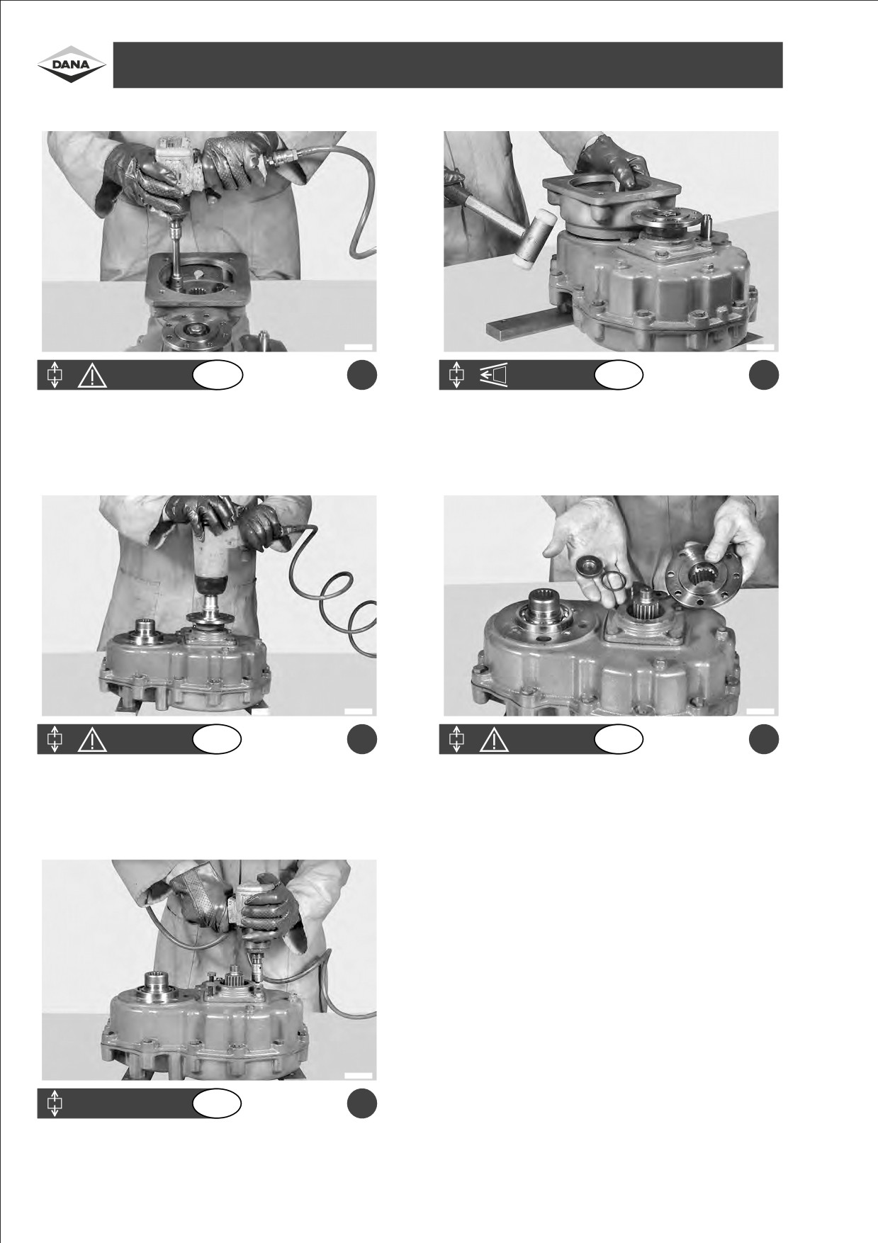
Remove screws from the motion input cover.
Disjoin the motion entrance cover.
F1240086
F1240087
GB
c
GB
d
Remove the nut from the flange.
Remove the O-ring and pull out the flange.
F1240088
GB
e
Remove screws from the cover.
16

Rimuovere le viti del coperchio di entrata del moto.
Staccare il coperchio di entrata del moto.
ITA
ITA
Die Deckelschrauben am Anfang der Bewegung
Deckel am Eingang des Bewegung abnehmen.
D
D
abschrauben.
a
b
Remover los tornillos de la tapa de entrada del
Desprender la tapa de entrada del movimiento.
ESP
ESP
movimiento.
Enlever les vis du couvercle d'entreÂe du mouvement.
D
 crocher le couvercle d'entreÂe du mouvement.
F
F
Rimuovere il dado della flangia.
Asportare l'anello OR ed estrarre la flangia.
ITA
ITA
Flanschmutter abschrauben.
O-Ring abnehmen und Flansch herausziehen.
D
D
c
d
Remover la tuerca de la brida.
Quitar el anillo OR y extraer la brida.
ESP
ESP
Enlever l'e crou de la flasque.
Enlever la bague OR et extraire la flasque.
F
F
Rimuovere le viti del coperchio.
ITA
Deckelschrauben abschrauben.
D
e
Remover los tornillos de la tapa.
ESP
Enlever les vis du couvercle.
F
17
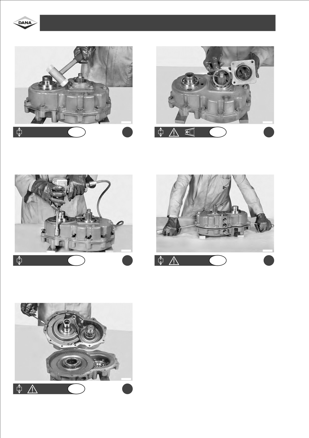
DISASSEMBLY OF DIRECTLY FLANGED REDUCTION GEAR 357- SMONTAGGIOGRUPPORIDUTTORE 357 AFFLANGIATO- DIREKT GEFLANSCHTER
REDUZIERER 357 ZERLEGEN - DESMONTAJE GRUPO REDUCTOR 357 CON BRIDA - DEMONTAGE DU GROUPE REDUCTEUR BRIDE 357
F1240089
F1240090
GB
a
GB
b
Disjoin the cover.
Remove the cover by fixing the distance washers onto the cover
itself.
Caution: the niche must be facing upwards.
F1240091
F1240092
GB
c
GB
d
Remove screws.
Remove the cover.
Take care not to damage planes.
F1240093
GB
e
Take away the cover.
Pay attention to the position of the pins.
18

Staccare il coperchio.
Rimuovere il coperchio fissando gli spessori allo
ITA
ITA
stesso.
Attenzione: nicchia rivolta verso l'alto.
Deckel abnehmen.
Deckel abnehmen und DistanzstuÈ cke am Deckel
D
D
befestigen.
Achtung: die Nische ist nach oben gerichtet.
a
b
Desprender la tapa.
Remover la tapa fijando los espesores en la misma.
ESP
ESP
Cuidado: el hueco tiene que estar dirigido hacia
arriba.
De crocher le couvercle.
Enlever le couvercle en fixant les cales aÁ ce dernier.
F
F
Attention: au logement tourne vers le haut.
Rimuovere le viti.
Rimuovere il coperchio.
ITA
ITA
Prestare attenzione per non danneggiare i piani.
Schrauben abschrauben.
Deckel abnehmen.
D
D
Darauf achten, die Fl
È chen nicht zu beschaÈdigen.
c
d
Remover los tornillos.
Remover la tapa.
ESP
ESP
Poner mucho cuidado a fin de no danÄ ar las superfi-
cies.
Enlever les vis.
Enlever le couvercle.
F
F
Faire attention aÁ ne pas endommager les surfaces.
Togliere il coperchio.
ITA
Prestare attenzione alla posizione delle spine.
Deckel abnehmen.
D
Auf die Position der Stifte achten.
e
Sacar la tapa.
ESP
Tener mucho cuidado con la posicioÂn de las clavijas.
Enlever le couvercle.
F
Faire attention aÁ la position des broches.
19
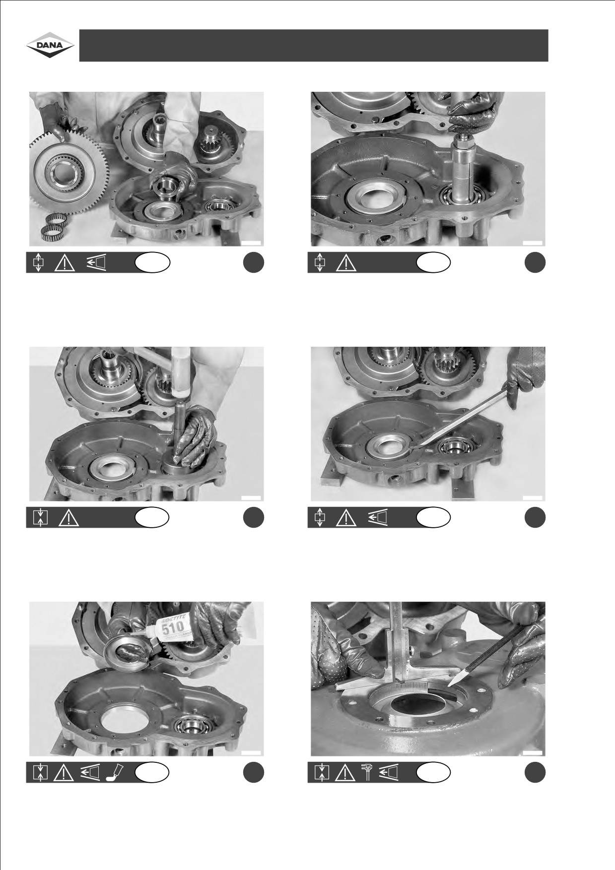
DISASSEMBLY OF DIRECTLY FLANGED REDUCTION GEAR 357- SMONTAGGIOGRUPPORIDUTTORE 357 AFFLANGIATO- DIREKT GEFLANSCHTER
REDUZIERER 357 ZERLEGEN - DESMONTAJE GRUPO REDUCTOR 357 CON BRIDA - DEMONTAGE DU GROUPE REDUCTEUR BRIDE 357
F1240094
F1240095
GB
a
GB
b
Pull out gear, needle bearings and distance piece form the box.
Remove the bearing if it needs replacing.
F1240096
F1240097
GB
c
GB
d
Re-introduce the bearing into the box.
Remove the oil shield plate only if necessary.
Caution: the oil inlet must face upwards.
F1240098
F1240099
GB
e
GB
f
Re-introduce the oil shield plate with oil inlet facing upwards.
Fit the oil shield plate into position 5±5.5 mm from box plane.
Apply LOCTITE 510 on the outside.
20

Estrarre dalla scatola l'ingranaggio, i cuscinetti a
Rimuovere il cuscinetto se eÁ da sostituire.
ITA
ITA
rullini ed il distanziale.
Aus der Schachtel das Zahnrad, die Kugellager und
Lager herausnehmen, wenn es ausgewechselt wer-
D
D
das DistanzstuÈ ck nehmen.
den soll.
a
b
Extraer de la caja el engranaje, los cojinetes de agujas
Remover el cojinete si hay que sustituirlo.
ESP
ESP
y el separador.
Extraire la boÃte d'engrenage, les paliers aÁ rouleaux et
Enlever le palier s'il est aÁ remplacer.
F
F
l'entretoise.
Reinserire il cuscinetto nella scatola.
Rimuovere la lamiera paraolio solo se necessario.
ITA
ITA
Attenzione: l'entrata dell'olio deve essere rivolta verso
l'alto.
Lager in die Schachtel einsetzen.
È labdichtung nur abnehmen, wenn es noÈ tig sein
D
D
sollte.
Achtung: der
È leingang muû nach oben gerichtet sein.
c
d
Volver a colocar el cojinete en la caja.
Remover el sello de aceite si fuera necesario.
ESP
ESP
Cuidado: la entrada del aceite tiene que estar dirigida
hacia arriba.
R
 inse rer le palier dans la boÃte.
Enlever la toà le pare-huile seulement si besoin.
F
F
Attention: l'orifice de huile doit
à tre tourneÂe vers le
haut.
Reinserire lamiera paraolio con l'entrata dell'olio verso
Posizionare la lamiera paraolio a 5v5,5 mm dal piano
ITA
ITA
l'alto.
scatola.
Spalmare sull'esterno LOCTITE 510.
È labdichtung mit dem Eingang nach oben wieder
È labdichtung in einem Abstand von 5v5,5 mm von
D
D
einsetzen.
der SchachtelflaÈ che einsetzen.
Auûen mit LOCTITE 510 schmieren.
e
f
Volver a colocar el sello de aceite con la entrada del
Posicionar el sello de aceite a
5v5,5 mm de la
ESP
ESP
aceite hacia arriba.
superficie de la caja.
Engrasar por fuera con LOCTITE 510.
R
 ins
 rer la toÃle pare-huile avec l'orifice de l'huile
Placer la t
à le pare-huile aÁ 5v5,5 mm de la surface de
F
F
tourneÂe vers le haut.
la boÃte.
Enduire du LOCTITE 510
Á l'exteÂrieur.
21
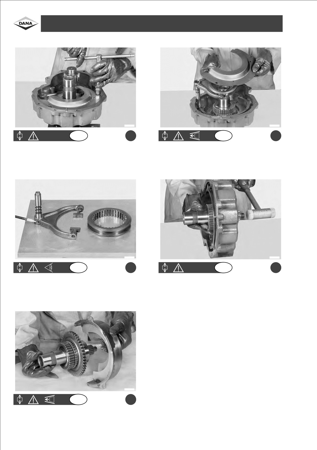
DISASSEMBLY OF DIRECTLY FLANGED REDUCTION GEAR 357- SMONTAGGIOGRUPPORIDUTTORE 357 AFFLANGIATO- DIREKT GEFLANSCHTER
REDUZIERER 357 ZERLEGEN - DESMONTAJE GRUPO REDUCTOR 357 CON BRIDA - DEMONTAGE DU GROUPE REDUCTEUR BRIDE 357
F1240100
F1240101
GB
a
GB
b
Remove the check screws from the flow regulator plate.
Remove the plate and pull out coupling and fork at the same time.
F1240102
F1240103
GB
c
GB
d
Check: sliding blocks, pin, and sliding coupling.
Remove the lower shaft.
Replace if worn.
F1240104
GB
e
Remove the entire shaft and the flow regulator plate.
22

Rimuovere le viti di ritegno lamiera frangiflusso.
Asportare la lamiera ed estrarre contemporaneamente
ITA
ITA
il manicotto e la forcella.
Befestigungsschrauben des Strahlreglers abschrau-
Strahlregler abnehmen und gleichzeitig HuÈ lse und
D
D
ben.
Gabel herausziehen.
a
b
Remover los tornillos de retencioÂn de la placa
Sacar la placa y extraer contempora neamente el
ESP
ESP
deflectora.
manguito y la horquilla.
Enlever les vis de fixation de la toà le brise-jet.
Enlever la t
Ãle et extraire, en meà me temps, le
F
F
manchon et la fourchette.
Verificare: pattini, spina e manicotto scorrevole.
Rimuovere l'albero di uscita.
ITA
ITA
Sostituirli se sono usurati.
Zu kontrollieren: Gleitschuhe, Stift und GleithuÈ lse.
Ausgangswelle abnehmen.
D
D
Wenn verschleiût, auswechseln.
c
d
Comprobar: patines, clavija y manguito corredizo.
Remover el eje de salida.
ESP
ESP
Sustituirlos si estaÂn gastados.
Ve rifier: pattes, broches et manchon coulissant.
De placer l'arbre de sortie.
F
F
Remplacer s'ils sont us
 s.
Asportare l'albero completo e la lamiera frangiflusso.
ITA
Die ganze Welle und den Strahlregler abnehmen.
D
e
Sacar el eje completo y la placa deflectora.
ESP
Enlever l'arbre au complet ainsi que la toÃle brise-jet.
F
23
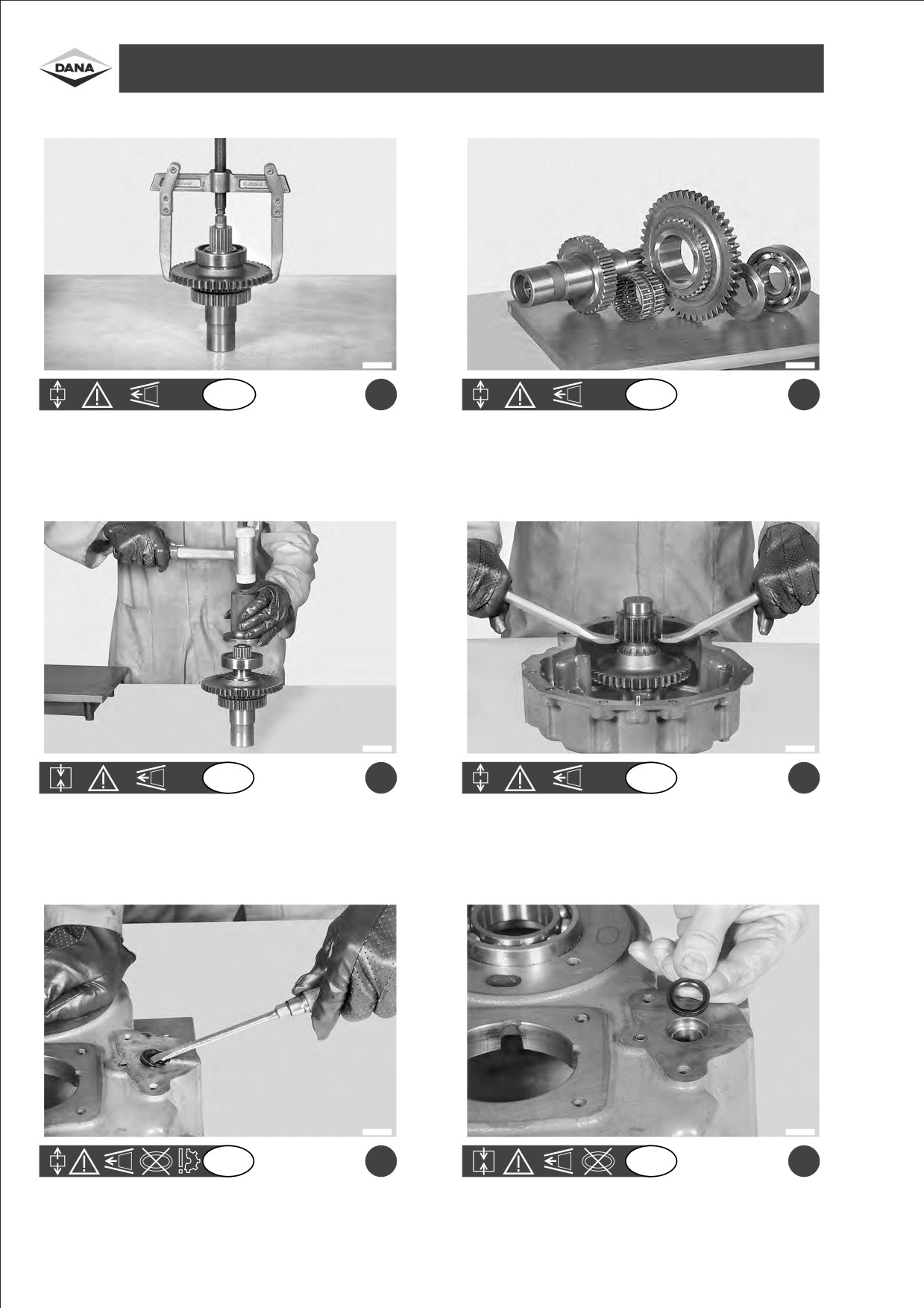
DISASSEMBLY OF DIRECTLY FLANGED REDUCTION GEAR 357- SMONTAGGIOGRUPPORIDUTTORE 357 AFFLANGIATO- DIREKT GEFLANSCHTER
REDUZIERER 357 ZERLEGEN - DESMONTAJE GRUPO REDUCTOR 357 CON BRIDA - DEMONTAGE DU GROUPE REDUCTEUR BRIDE 357
F1240105
F1240106
GB
a
GB
b
Disassembly of the entire lower shaft.
Progressive arrangement of parts fitted onto the lower shaft.
F1240107
F1240108
GB
c
GB
d
Assembly of lower shaft.
Removal of upper shaft.
(In case of replacement, the shaft is supplied already assembled).
F1240109
F1240110
GB
e
GB
f
Pull out the sealing ring.
Re-insert a new sealing ring.
24

Smontaggio dell'albero di uscita completo.
Disposizione progressiva dei particolari montati su
ITA
ITA
albero di uscita.
Ganze Ausgangswelle abmontieren.
Reihenfolge der auf der Ausgangswelle montierten
D
D
Einzelteile.
a
b
Desmontaje del eje de salida completo.
DisposicioÂn progresiva de las piezas montadas en el
ESP
ESP
eje de salida.
De montage complet de l'arbre de sortie.
Mise en place progressive des pi
Á ces monte es sur
F
F
l'arbre de sortie.
Assemblaggio dell'albero di uscita.
Rimuovere l'albero di entrata.
ITA
ITA
(Nel caso di sostituzione, viene fornito premontato).
Zusammenbau der Ausgangswelle.
Eingangswelle entfernen.
D
D
(Bei Ersatz, wird sie schon montiert geliefert).
c
d
Montaje del eje de salida.
Remover el eje de entrada.
ESP
ESP
(En el caso de sustitucio n, se entrega ya premontado).
Assemblage de l'arbre de sortie.
D
 placer l'arbre d'entr
 e.
F
F
(En cas de substitution, il est fourni pr
 mont
 ).
Estrarre l'anello di tenuta.
Reinserire il nuovo anello di tenuta.
ITA
ITA
Dichtungsring herausziehen.
Den neuen Dichtungsring einsetzen.
D
D
e
f
Extraer el segmento de compresi
 n.
Volver a insertar el segmento de compresi
 n.
ESP
ESP
Extraire la bague d'
 tanch
 it
Â.
Introduire la bague d'
Âtanch
 ite neuve.
F
F
25
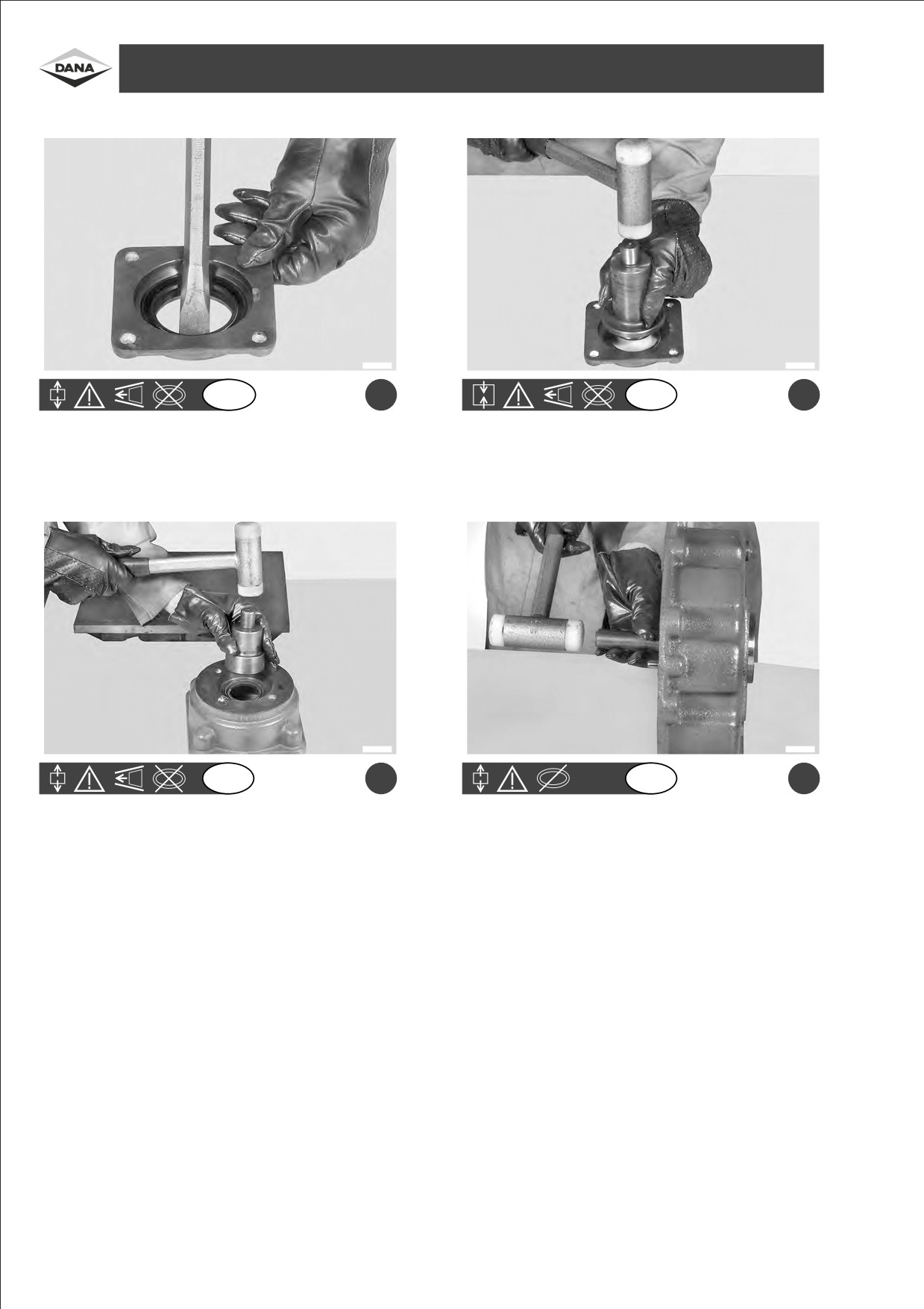
DISASSEMBLY OF DIRECTLY FLANGED REDUCTION GEAR 357- SMONTAGGIOGRUPPORIDUTTORE 357 AFFLANGIATO- DIREKT GEFLANSCHTER
REDUZIERER 357 ZERLEGEN - DESMONTAJE GRUPO REDUCTOR 357 CON BRIDA - DEMONTAGE DU GROUPE REDUCTEUR BRIDE 357
F1240111
F1240112
GB
a
GB
b
Pull out the sealing ring of the cover.
Re-insert a new sealing ring.
F1240113
F1240114
GB
c
GB
d
Pull out the sealing ring from the motion input cover.
Remove the bearing from the cover of the reduction unit.
26

Estrarre l'anello di tenuta del coperchio.
Reinserire il nuovo anello di tenuta.
ITA
ITA
Dichtungsring des Deckels herausziehen.
Den neuen Dichtungsring einsetzen.
D
D
a
b
Extraer el segmento de compresioÂn de la tapa.
Insertar el nuevo segmento de compresi
 n.
ESP
ESP
Extraire la bague d'
 tanch
 ite du couvercle.
Introduire la bague d'
Âtanch
 ite neuve.
F
F
Estrarre l'anello di tenuta dal coperchio di ingresso del
Rimuovere il cuscinetto dal coperchio riduttore.
ITA
ITA
moto.
Dichtungsring am Anfang der Bewegung herauszie-
Lager des Reduziererdeckels entfernen.
D
D
hen.
c
d
Extraer el segmento de compresioÂn de la tapa de
Remover el cojinete de la tapa del reductor.
ESP
ESP
entrada del movimiento.
Extraire la bague d'
 tanch
 it
 du couvercle d'entr
Âe
Enlever le palier du couvercle du re ducteur.
F
F
du mouvement.
27
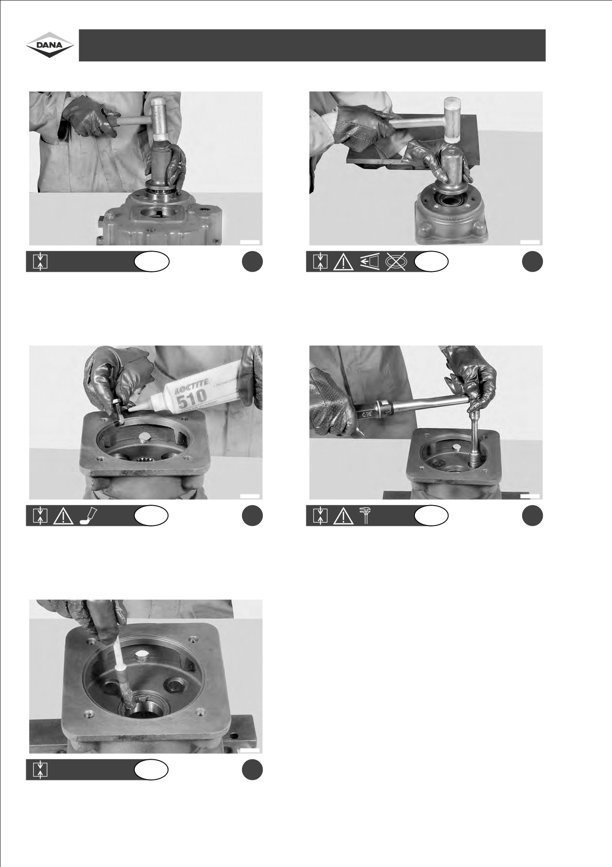
ASSEMBLY OF DIRECTLY FLANGEDREDUCTIONGEAR357 - ASSEMBLAGGIOGRUPPORIDUTTORE 357 AFFLANGIATO- DIREKT GEFLANSCHTER
REDUZIERER 357 MONTIEREN - MONTAJE GRUPO REDUCTOR 357 CON BRIDA - ASSEMBLAGE DU GROUPE REDUCTEUR BRIDE 357
F1240115
F1240116
GB
a
GB
b
Re-fit the bearing in the cover of the reduction unit using ordinary
Re-insert the new sealing ring in the motion input cover.
tools.
F1240117
F1240118
GB
c
GB
d
Re-assemble the cover, spreading LOCTITE 510 on planes and
Tighten screws using a torque wrench setting of 49±51 Nm.
screws.
F1240119
GB
e
Lubricate the lip of the sealing ring with grease.
28

Rimontare il cuscinetto nel coperchio riduttore con i
Reinserire il nuovo anello di tenuta coperchio di
ITA
ITA
normali attrezzi.
ingresso del moto.
Lager in den Reduziererdeckel mit gewoÈ hnlichen
Den neuen Dichtungsring in den Deckel am Eingang
D
D
Werkzeugen montieren.
der Bewegung montieren.
a
b
Volver a montar el cojinete en la tapa del reductor con
Volver a insertar el nuevo segmento de compresi
Ân en
ESP
ESP
las herramientas normales.
la tapa de entrada del movimiento.
Remonter le palier du couvercle r
 ducteur aÁ l'aide
Introduire la bague d'
Âtanch
Âite neuve dans le
F
F
d'outils habituels.
couvercle d'entreÂe du mouvement.
Rimontare il coperchio spalmando sui piani e sulle viti
Serrare le viti con una coppia di serraggio di
ITA
ITA
LOCTITE 510.
49v51 Nm.
DeckelflaÈ chen und
-schrauben mit LOCTITE 510
Schrauben mit einem Anziehdrehmoment zu
D
D
schmieren und montieren.
49v51 Nm anziehen.
c
d
Volver a montar la tapa engrasando las superficies y
Apretar los tornillos a un par de torsioÂn de di
ESP
ESP
los tornillos con LOCTITE 510.
49v51 Nm.
Remonter le couvercle en e talant du LOCTITE 510 sur
Serrer les vis aÁ un couple de serrage de
F
F
les surfaces et sur les vis.
49v51 Nm.
Lubrificare con grasso il labbro dell'anello di tenuta.
ITA
Dichtlippe mit Fett schmieren.
D
e
Lubricar con grasa el labio del segmento de compre-
ESP
si
 n.
Lubrifier avec du gras la l
Á vre de la bague d'e tan-
F
ch
 it
Â.
29
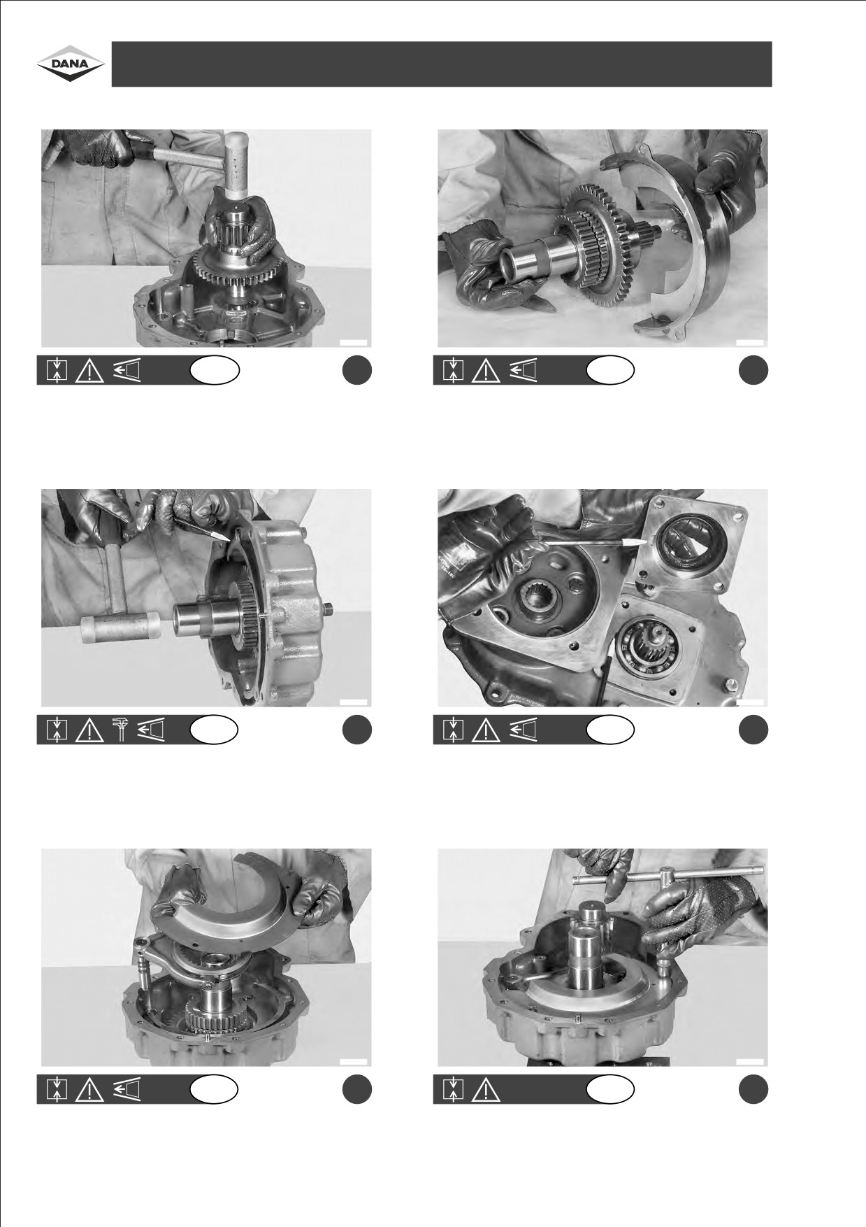
ASSEMBLY OF DIRECTLY FLANGEDREDUCTIONGEAR357 - ASSEMBLAGGIOGRUPPORIDUTTORE 357 AFFLANGIATO- DIREKT GEFLANSCHTER
REDUZIERER 357 MONTIEREN - MONTAJE GRUPO REDUCTOR 357 CON BRIDA - ASSEMBLAGE DU GROUPE REDUCTEUR BRIDE 357
F1240120
F1240104
GB
a
GB
b
Re-assemble the motion upper shaft.
Re-assemble the full lower shaft and the flow regulator plate.
F1240121
F1240122
GB
c
GB
d
Position the shaft so that the bearing juts out approximately 5 mm
Temporarily re-assemble the cover with screws.
from the cover of the reduction unit.
(Be sure that the niche faces upwards).
F1240101
F1240100
GB
e
GB
f
Simultaneously insert: fork and sliding blocks, coupling and flow
Re-insert screws and tighten.
regulator plate.
30

Rimontare l'albero di entrata del moto.
Rimontare l'albero uscita completo e la lamiera
ITA
ITA
frangiflusso.
Welle am Eingang der Bewegung montieren.
Ganze Ausgangswelle und Strahlregler montieren.
D
D
a
b
Volver a montar el eje de entrada del movimiento.
Volver a montar el eje de salida completo y la placa
ESP
ESP
deflectora.
Remonter l'arbre d'entreÂe du mouvement.
Remonter l'arbre de sortie tout entier et la toà le brise-
F
F
jet.
Posizionare l'albero in modo che il cuscinetto sporga
Rimontare provvisoriamente il coperchio con le viti.
ITA
ITA
dal coperchio riduttore circa 5 mm.
(Attenzione alla nicchia che deve essere rivolta verso
l'alto).
Die Welle so positionieren, daû das Lager vom
VoruÈbergehend den Deckel mit den Schrauben
D
D
Reduziererdeckel ca. 5 mm herausragt.
montieren.
(Achtung, die Nische muû nach oben gerichtet sein).
c
d
Posicionar el eje de manera que el cojinete sobresalga
Volver a montar provisionalmente la tapa con los
ESP
ESP
de la tapa del reductor en unos 5 mm aproximada-
tornillos. (Cuidado con el hueco que tiene que estar
mente.
dirigido hacia arriba).
Positionner l'arbre de telle sorte que le palier saillisse
Remonter provisoirement le couvercle avec les vis.
F
F
du couvercle du re ducteur d'environ 5 mm.
(Attention le logement doit
à tre tourne vers le haut).
Reinserire contemporaneamente: la forcella con patti-
Reinserire le viti ed avvitarle.
ITA
ITA
ni, il manicotto e la lamiera frangiflusso.
Gleichzeitig Gabel mit Gleitschuh, HuÈ lse und Strahl-
Schrauben anbringen und festschrauben.
D
D
regler montieren.
e
f
Volver a insertar contempora neamente la horquilla
Volver a introducir los tornillos y atornillarlos.
ESP
ESP
con los patines, el manguito y la placa deflectora.
R
 ins
 rer en meà me temps: la fourchette avec les
Introduire les vis et visser.
F
F
pattes, le manchon et la toà le brise-jet.
31
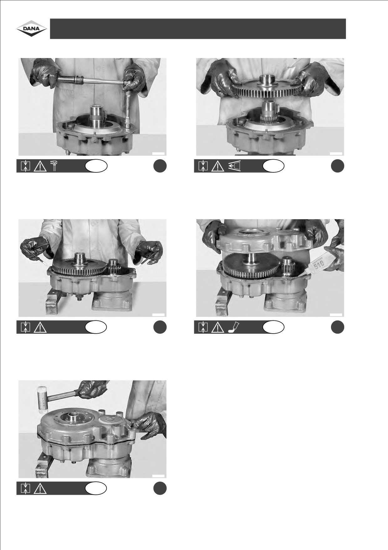
ASSEMBLY OF DIRECTLY FLANGEDREDUCTIONGEAR357 - ASSEMBLAGGIOGRUPPORIDUTTORE 357 AFFLANGIATO- DIREKT GEFLANSCHTER
REDUZIERER 357 MONTIEREN - MONTAJE GRUPO REDUCTOR 357 CON BRIDA - ASSEMBLAGE DU GROUPE REDUCTEUR BRIDE 357
F1240123
F1240124
GB
a
GB
b
Tighten screws using a torque wrench setting of 25±26 Nm.
Re-assemble needle bearings, gear and distance piece.
F1240125
F1240126
GB
c
GB
d
Check the insertion of pins.
Spread LOCTITE 510 on the surface and assemble the cover.
F1240127
GB
e
Fasten the cover.
32

Serrare le viti con una coppia di serraggio di
Rimontare i cuscinetti a rullini, l'ingranaggio ed il
ITA
ITA
25v26 Nm.
distanziale.
Schrauben mit einem Anziehdrehmoment zu
Kugellager, Zahnrad und DistanzstuÈ ck montieren.
D
D
25v26 Nm anziehen.
a
b
Apretar los tornillos a un par de torsi
Ân de
Volver a montar los cojinetes de agujas, el engranaje y
ESP
ESP
25v26 Nm.
el separador.
Serrer les vis aÁ un couple de serrage de
Remonter les paliers aÁ rouleaux, l'engrenage et
F
F
25v26 Nm.
l'entretoise.
Verificare l'inserimento delle spine.
Spalmare la superficie con LOCTITE 510 e montare il
ITA
ITA
coperchio.
Einsatz der Stifte kontrollieren.
FlaÈ che mit LOCTITE 510 schmieren und Deckel
D
D
montieren.
c
d
Comprobar la insercioÂn de las clavijas.
Engrasar la superficie con LOCTITE 510 y montar la
ESP
ESP
tapa.
Ve rifier l'introduction des broches.
Enduire la surface avec du LOCTITE 510 et monter le
F
F
couvercle.
Mandare il coperchio in battuta.
ITA
Den Deckel zum Anschlag bringen.
D
e
Llevar la tapa a tope.
ESP
Lancer le couvercle but
 e.
F
33
ASSEMBLY OF DIRECTLY FLANGEDREDUCTIONGEAR357 - ASSEMBLAGGIOGRUPPORIDUTTORE 357 AFFLANGIATO- DIREKT GEFLANSCHTER
REDUZIERER 357 MONTIEREN - MONTAJE GRUPO REDUCTOR 357 CON BRIDA - ASSEMBLAGE DU GROUPE REDUCTEUR BRIDE 357
F1240128
F1240082
GB
a
GB
b
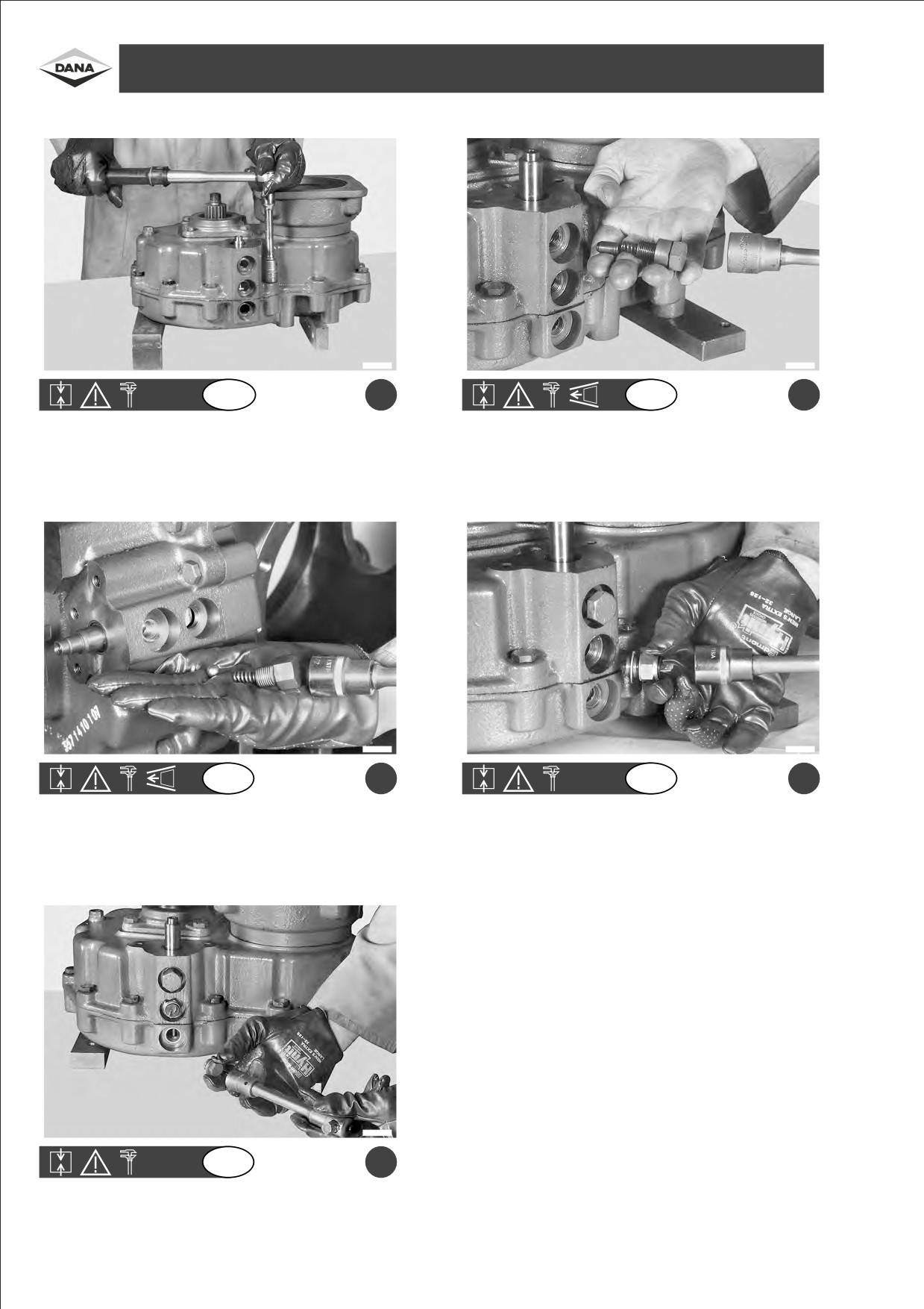
Tighten screws using a torque wrench setting of
49±51 Nm.
Grease components and re-introduce spindle, spring and screw
Caution: tighten using the crossed method.
(mechanical version).
Tighten using a max. torque wrench setting of 80±100 Nm.
F1240083
F1240081
GB
c
GB
d
Grease components and re-introduce ball, spring and screw
Fix the gear-in position switch with washer and O-ring.
(hydraulic version).
Tighten with torque wrench setting of max. 54.2 Nm.
Tighten using a max. torque wrench setting of 80±100 Nm.
F1240080
GB
e
Assemble the sealing cover with washer and revolution indicator.
Tighten using a torque wrench setting of max. 25 Nm.
34
//////////////////////////////////////////