Takeuchi Gear Box 357A10. Service Manual (1998) - page 2

Serrare le viti con una coppia di serraggio di
Ingrassare i componenti e reinserire il puntalino, la
ITA
ITA
49v51 Nm.
molla, la vite (versione meccanica). Serrare con una
Attenzione: serrare con il metodo incrociato.
coppia di serraggio max. di 80v100 Nm.
Schrauben mit einem Anziehdrehmoment zu
Einzelteile schmieren und Stift, Feder und Schraube
D
D
49v51 Nm anziehen.
einsetzen (mechanische AusfuÈ hrung). Mit einem An-
Achtung: Schrauben abwechselnd im Kreuz anziehen.
ziehdrehmoment zu max. 80v100 Nm anziehen.
a
b
Apretar los tornillos a un par de torsi
Ân de
Engrasar los componentes y volver a insertar el
ESP
ESP
49v51 Nm.
pasador, el muelle, el tornillo (versi
Ânmeca nica).
Cuidado: apretar con el me todo cruzado.
Apretar a un par de torsi
Ânma x. dei 80v100 Nm.
Serrer les vis aÁ un couple de serrage de
Graisser les composants et r
 ins
 rer la bute e, le
F
F
49v51 Nm.
ressort, la vis (mod
Á le me canique).
Attention: serrer avec la m
 thode crois
Âe.
Serrer aÁ un couple de serrage max. de 80(100 Nm.
Ingrassare i componenti e reinserire la sfera, la molla e
Montare l'interruttore di posizione marcia inserita con
ITA
ITA
la vite (versione idraulica).
rosetta e anello OR.
Serrare con una coppia max. di 80v100 Nm.
Serrare con una coppia di serraggio max. di 54,2 Nm.
Einzelteile schmieren und Kugel, Feder und Schraube
Schalter fuÈr die Position der Gangschaltung mit
D
D
einsetzen (hydraulische AusfuÈ hrung). Mit einem An-
Unterlegscheibe und O-Ring montieren. Mit einem
ziehdrehmoment zu 80v100 Nm anziehen.
Anziehdrehmoment zu max. 54,2 Nm anziehen.
c
d
Engrasar los componentes y volver a colocar la bola,
Montar el interruptor de posicioÂn marcha embragada
ESP
ESP
el muelle y el tornillos (versi
Ânhidra ulica).
con roseta y anillo OR.
Apretar a un par ma x. dei 80v100 Nm.
Apretar a un par de torsi
Ânma x. de 54,2 Nm.
Graisser les composants et r
 ins
 rer la spheÁ re, le
Monter l'interrupteur de position de vitesses incorpor
Â
F
F
ressort et la vis (modeÁ le hydraulique).
avec la rondelle et la bague OR.
Serrer aÁ un couple max. de 80v100 Nm.
Serrer aÁ un couple de serrage max. de 54,2 Nm.
Montare tappo di chiusura con rosetta e rilevatore di
ITA
giri. Serrare con una coppia max. di 25 Nm.
Stopfen mit Unterlegscheibe und Drehzahlmesser
D
montieren. Mit einem Anziehdrehmoment zu max. 25
Nm anziehen.
e
Montar el tapoÂn de cierre con la roseta y el detector de
ESP
revoluciones. Apretar a un par ma x. de 25 Nm.
Monter le bouchon de verrouilllage accompagne de la
F
rondelle et du compteur de tours. Serrer aÁ un couple
max. de 25 Nm.
35
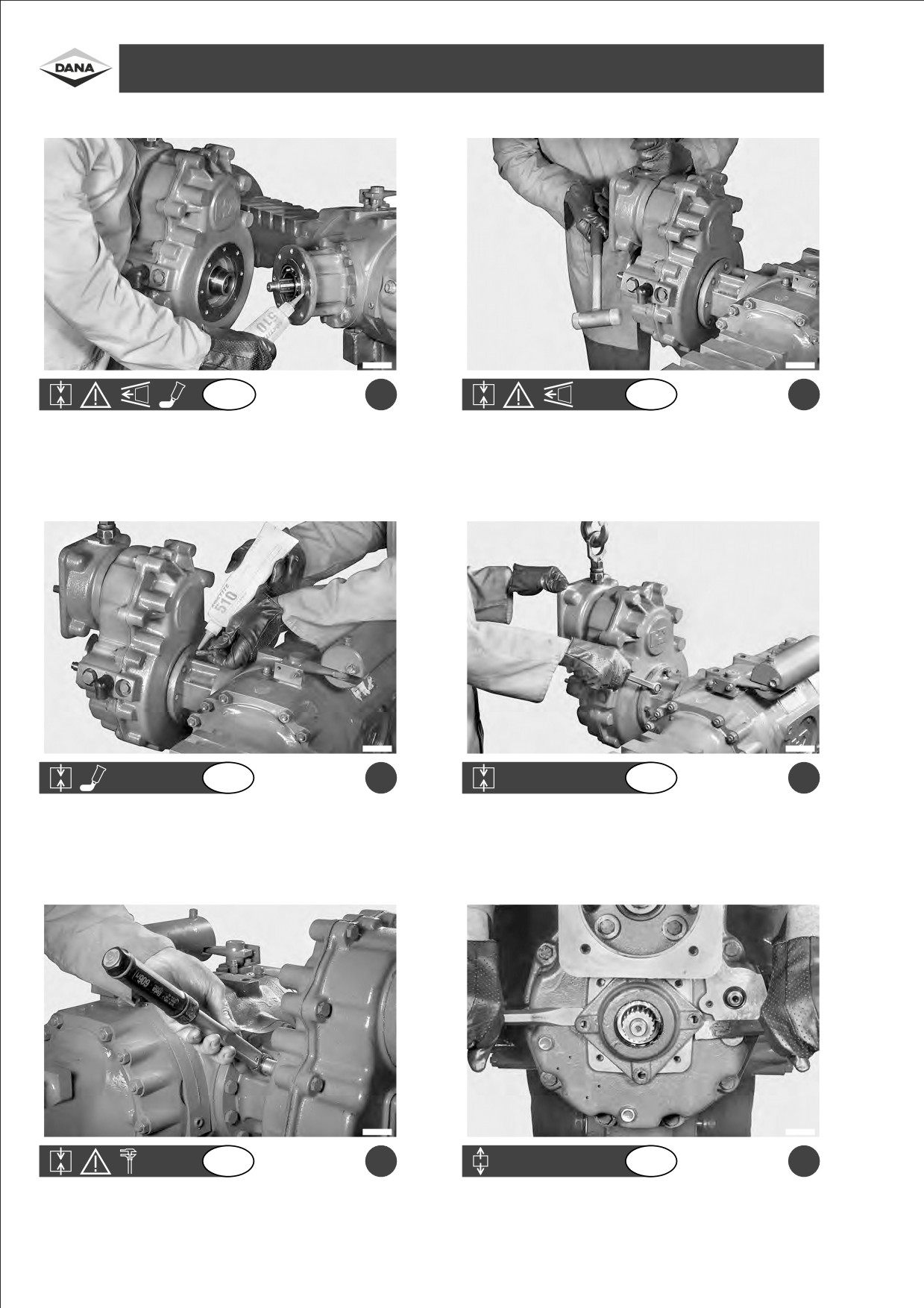
ASSEMBLY OF DIRECTLY FLANGEDREDUCTIONGEAR357 - ASSEMBLAGGIOGRUPPORIDUTTORE 357 AFFLANGIATO- DIREKT GEFLANSCHTER
REDUZIERER 357 MONTIEREN - MONTAJE GRUPO REDUCTOR 357 CON BRIDA - ASSEMBLAGE DU GROUPE REDUCTEUR BRIDE 357
F1240129
F1240130
GB
a
GB
b
Re-fit the reduction unit onto the axle by spreading LOCTITE 510
Fasten the support planes (turn flange to assist assembly).
on the planes.
F1240131
F1240132
GB
c
GB
d
Insert screws by applying LOCTITE 510.
Screw down by placing the reduction unit in a vertical position in
relation to the axis.
F1240133
F1240134
GB
e
GB
f
Tighten screws using a torque wrench setting of 49±51 Nm.
Extract screws and remove the temporarily assembled cover.
36

Rimontare il riduttore sul ponte spalmando i piani con
Mandare in battuta i piani di appoggio (ruotare la
ITA
ITA
LOCTITE 510.
flangia per facilitare il montaggio).
Reduzierer auf die Triebachse montieren; zuvor die
AuflageflaÈ chen bis zum Anschlag bringen (Flansch
D
D
FlaÈ chen mit LOCTITE 510 schmieren.
drehen um die Montage zu erleichtern).
a
b
Volver a montar el reductor en el puente engrasando
Llevar a tope las superficies de apoyo (girar la brida
ESP
ESP
las superficies con LOCTITE 510.
para facilitar el montaje).
Remonter le r
Âducteur au pont en e talant sur les
Lancer les surfaces d'appui en but
Âe
(tourner la
F
F
surfaces du LOCTITE 510.
flasque pour faciliter le montage).
Inserire le viti spalmandole con LOCTITE 510.
Avvitare le viti posizionando il riduttore in modo
ITA
ITA
verticale rispetto l'asse.
Schrauben mit LOCTITE 510 schmieren und ein-
Schrauben festschrauben; dabei den Reduzierer
D
D
setzen.
senkrecht zur Achse halten.
c
d
Insertar los tornillos engrasa ndolos con LOCTITE 510.
Atornillar los tornillos posicionando el reductor de
ESP
ESP
manera vertical con respecto al eje.
Introduire les vis en les enduisant d'abord de
Visser les vis en pla
Ëant le re ducteur verticalement par
F
F
LOCTITE 510.
rapport aÁ l'axe.
Serrare le viti con una coppia di serraggio di
Asportare le viti e rimuovere il coperchio montato
ITA
ITA
49v51 Nm.
provvisoriamente
Schrauben mit einem Anziehdrehmoment zu
Schrauben abschrauben und voruÈ bergehend montier-
D
D
49v51 Nm anziehen.
ter Deckel abnehmen.
e
f
Apretar los tornillos a un par de torsi
Ân de
Sacar los tornillos y remover la tapa montada
ESP
ESP
49v51 Nm.
provisionalmente.
Serrer les vis aÁ un couple de serrage de
Enlever les vis et enlever le couvercle provisoirement
F
F
49v51 Nm.
mont
Â.
37
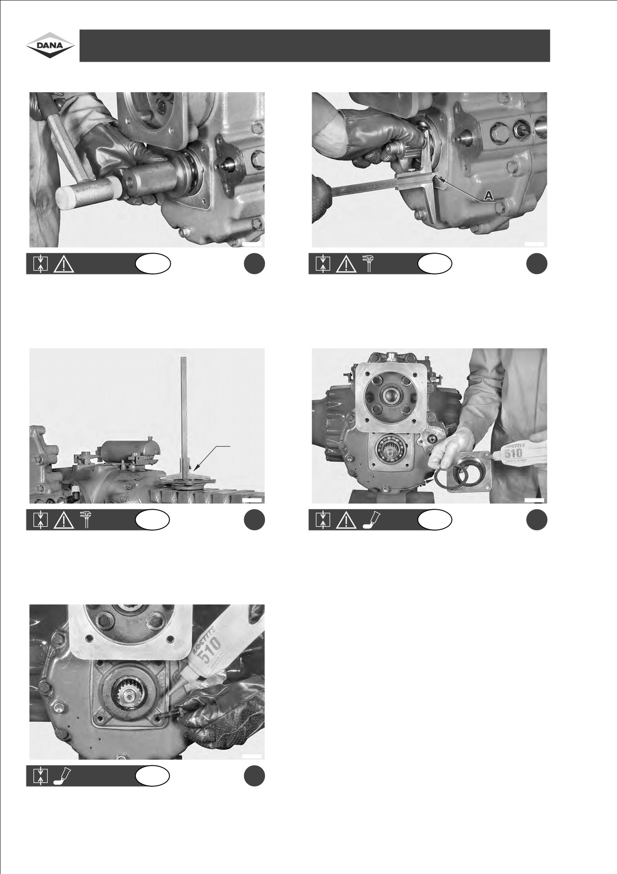
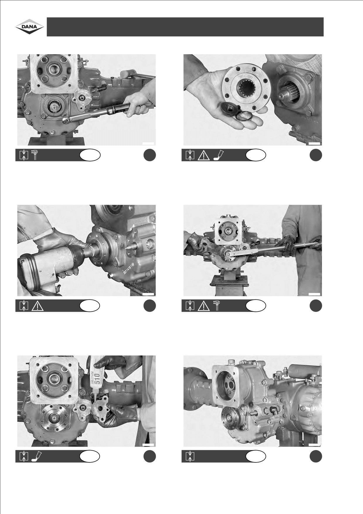
ASSEMBLY OF DIRECTLY FLANGEDREDUCTIONGEAR357 - ASSEMBLAGGIOGRUPPORIDUTTORE 357 AFFLANGIATO- DIREKT GEFLANSCHTER
REDUZIERER 357 MONTIEREN - MONTAJE GRUPO REDUCTOR 357 CON BRIDA - ASSEMBLAGE DU GROUPE REDUCTEUR BRIDE 357
F1240135
F1240136
GB
a
GB
b
Fasten the bearing by using a standard tool.
Measure dimension "A" between the bearing and the box plane
using an ordinary depth gauge (if parts are not replaced, use
disassembled distance washers).
B
S
F1240137
F1240138
GB
c
GB
d
Measure dimension "B" on the cover, between the bearing plane
Apply LOCTITE 510 on the surface, lubricate the sealing ring,
and bearing support. Calculate the dimension of the distance
insert the distance washers and re-assemble the cover with niche
washers required:
facing upwards.
S=Dimension B Ð Dimension A
Es: B=5.2±A=4.6 mm ± Backlash 0.2±0.3=Distance washer
required=0.4±0.3.
F1240139
GB
e
Fit screws after applying LOCTITE 510.
38

Mandare in battuta il cuscinetto utilizzando un
Rilevare la quota "A" fra cuscinetto e piano scatola
ITA
ITA
normale attrezzo.
usando un normale calibro di profondit
Á.
(Se non vengono sostituiti pezzi, utilizzare gli spessori
smontati).
Das Lager bis zum Anschlag bringen; dazu ein
Maû "A" zwischen Lager und SchachtelflaÈ che mit
D
D
gewoÈ hnliches Werkzeug verwenden.
einem gewoÈ hnlichen Kaliber messen
(wenn keine
Teile ausgewechselt werden, die abmontierten Di-
stanzstuÈ cke verwenden).
a
b
Llevar a tope el cojinete utilizando una herramienta
Registrar la cota "A" entre el cojinete y la superficie de
ESP
ESP
normal.
la caja utilizando un normal calibre de profundidad.
(Si no se sustituyen las piezas, utilizar los espesores
desmontados).
Lancer en but
ÂelepalieraÁ l'aide d'un outil normal.
Relever la cote "A" entre palier et surface de la boÃte
Á
F
F
l'aide d'un calibre de profondeur normal (S'il n'y a pas
de pi
Á ces
Á remplacer, utiliser les cales d
 monte es).
Rilevare la quota "B" sul coperchio fra piano e
Spalmare la superficie con LOCTITE 510, lubrificare
ITA
ITA
appoggio cuscinetto. Calcolare gli spessori da inserire
l'anello di tenuta, inserire gli spessori e rimontare il
S=Quota B±Quota A
coperchio con la nicchia rivolta verso l'alto.
Es: B=5,2±A=4,6 mm ± Gioco 0,2v0,3= Spessore da inseri-
re=0,4v0,3
Maû "B" am Deckel zwischen FlaÈ che und Auflage-
FlaÈ che mit LOCTITE 510 schmieren; Dichtungsring
D
D
flaÈ che des Lagers messen. Die einzulegenden Di-
schmieren; DistanzstuÈ cke einsetzen und Deckel mit
stanzstuÈ cke ausrechnen. S=Maû B±Maû A
Nische nach oben gerichtet, montieren.
Bsp: B=5,2±A=4,6 mm ± Spiel 0,2v0,3=einzusetzende Distanz-
c
stuÈ cke=0,4v0,3
d
Registrar la cota "B" en la tapa entre la superficie y el
Engrasar la superficie con LOCTITE 510, lubricar el
ESP
ESP
soporte del cojinete. Calcular los espesores que hay
segmento de compresio n, insertar los espesores y
que insertar S
= Cota B±Cota A
volver a montar la tapa con el hueco dirigido hacia
Es: B=5,2±A=4,6 mm ± Juego 0,2v0,3= Espesor a inser-
arriba.
tar=0,4v0,3
Relever la cote "B" sur le couvercle entre surface et
Enduire la surface de LOCTITE 510, lubrifier la bague
F
F
support palier. Calculer le nombre de cales
Á
d'
 tanch
 iteÂ, introduire les cales et remonter ensuite
introduire S=Cote B±Cote A
le couvercle avec le logement tourne vers le haut.
Exp: B=5,2±A=4,6 mm ± Jeu 0,2v0,3=Cales aÁ introduire
=0,4v0,3
Inseire le viti dopo everle spalmate con
ITA
LOCTITE 510.
Schrauben einsetzen; zuvor mit LOCTITE 510
D
schmieren.
e
Introducir los tornillos despueÂs de engrasarlos con
ESP
LOCTITE 510.
Introduire les vis apreÁs les avoir enduites de
F
LOCTITE 510.
39
ASSEMBLY OF DIRECTLY FLANGEDREDUCTIONGEAR357 - ASSEMBLAGGIOGRUPPORIDUTTORE 357 AFFLANGIATO- DIREKT GEFLANSCHTER
REDUZIERER 357 MONTIEREN - MONTAJE GRUPO REDUCTOR 357 CON BRIDA - ASSEMBLAGE DU GROUPE REDUCTEUR BRIDE 357
F1240140
F1240141
GB
a
GB
b
Tighten screws using a torque wrench setting of 49±51 Nm.
Assemble flange, O-ring and nut using LOCTITE 242.
F1240142
F1240143
GB
c
GB
d
Screw down the nut of the flange.
Tighten the nut using a torque wrench setting of 260±280 Nm.
F1240144
F1240069
GB
e
GB
f
Re-fix the protection plate after applying LOCTITE 510.
Complete flanged reduction gear 357 with mechanical gear control.
40

Serrare le viti con una coppia di serraggio di
Montare la flangia, l'anello OR e il dado con
ITA
ITA
49v51 Nm.
LOCTITE 242.
Schrauben mit einem Anziehdrehmoment zu
Flansch, O-Ring und Mutter mit LOCTITE 242
D
D
49v51 Nm anziehen.
schmieren und montieren.
a
b
Apretar los tornillos a un par de torsi
Ân de
Montar la brida, el anillo OR y la tuerca con
ESP
ESP
49v51 Nm.
LOCTITE 242.
Serrer les vis aÁ un couple de serrage de
Monter la flasque, la bague OR et l'e crou enduit de
F
F
49v51 Nm.
LOCTITE 242.
Avvitare il dado della flangia.
Serrare il dado con una coppia di serraggio di
ITA
ITA
260v280 Nm.
Flanschmutter festschrauben.
Mutter mit einem Anziehdrehmoment zu
D
D
260v280 Nm anziehen.
c
d
Atornillar la tuerca de la brida.
Apretar la tuerca a un par de torsi
Ân de
ESP
ESP
260v280 Nm.
Visser l'e crou de la flasque.
Serrer l'
 crou aÁ un couple de serrage de
F
F
260v280 Nm.
Rimontare lamiera di protezione dopo everla spalmata
Gruppo riduttore 357 afflangiato con comando marcia
ITA
ITA
con LOCTITE 510.
meccanico completo.
Schutzblech mit LOCTITE 510 schmieren und mon-
Ganzes direkt geflanschter Reduzierer 357 mit me-
D
D
tieren.
chanischer Gangschaltung.
e
f
Volver a montar la placa de protecci
Ân despu
Âs de
Grupo reductor 357 con brida con mando de marcha
ESP
ESP
engrasarla con LOCTITE 510.
meca nico completo.
Remonter la t
à le de protection apreÁs l'avoir enduite de
Groupe r
 ducteur brid
 357 aÁ commande de vitesses
F
F
LOCTITE 510.
me canique complet.
41
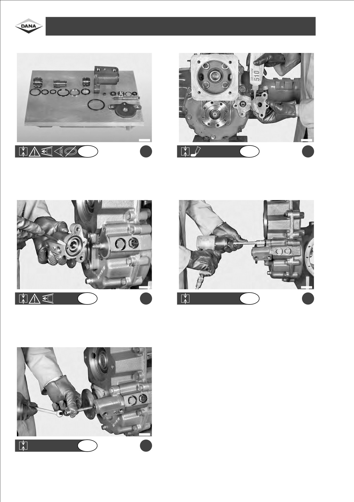
ASSEMBLY OF DIRECTLY FLANGEDREDUCTIONGEAR357 - ASSEMBLAGGIOGRUPPORIDUTTORE 357 AFFLANGIATO- DIREKT GEFLANSCHTER
REDUZIERER 357 MONTIEREN - MONTAJE GRUPO REDUCTOR 357 CON BRIDA - ASSEMBLAGE DU GROUPE REDUCTEUR BRIDE 357
F1240145
F1240144
GB
a
GB
b
Re-assemble all the parts of the gear control cylinder, according to
Re-fix the protection plate after applying LOCTITE 510 on it.
their arrangement.
F1240146
F1240147
GB
c
GB
d
Re-fit the gear control cylinder into place with its O-ring.
Re-fit screws and screw down.
F1240148
GB
e
Re-introduce the gear control rod after applying LOCTITE 242 on it.
42

Rimontare tutti i particolari del cilindro comando
Rimontare lamiera di protezione dopo averla spalmata
ITA
ITA
marcia come disposti in ordine.
con LOCTITE 510.
Alle Einzelteile des Zylinders des Gangschalters der
Schutzblech mit LOCTITE 510 schmieren und mon-
D
D
Reihenfolge nach montieren.
tieren.
a
b
Volver a montar todas las piezas del cilindro mando
Volver a montar la placa de protecci
Ân despu
Âs de
ESP
ESP
marcha dispuestos en su orden.
engrasarla con LOCTITE 510.
Remonter toutes les pieÁces du cylindre de commande
Remonter la t
à le de protection apreÁs l'avoir enduite de
F
F
de vitesses place dans l'ordre.
LOCTITE 510.
Rimontare il cilindro comando marcia completo di
Reinserire le viti ed avvitarle.
ITA
ITA
anello OR.
Zylinder des Gangschalters mit O-Ring montieren.
Schrauben einsetzen und festschrauben.
D
D
c
d
Volver a montar el cilindro mando marcha completo de
Volver a introducir los tornillos y atornillarlos.
ESP
ESP
anillo OR.
Remonter le cylindre de commande de vitesses
Introduire les vis et visser.
F
F
complet de bague OR.
Reinserire asta di comando marcia dopo averla
ITA
spalmata con LOCTITE 242.
Gangschalterhebel mit LOCTITE 242 schmieren und
D
montieren.
e
Volver a insertar la varilla de mando de la marcha
ESP
despueÂs de engrasarla con LOCTITE 242.
Introduire la tringle de commande de vitesses apr
Ás
F
l'avoir enduite de LOCTITE 242.
43
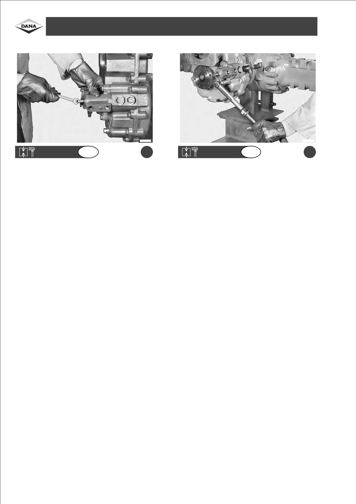
INSTALLATION OF HYDRAULIC GEAR CONTROL - INSTALLAZIONE COMANDO MARCIA IDRAULICO - HYDRAULISCHER GANGSCHALTUNG
MONTIEREN - MONTAJE MANDO MARCHA HIDRAULICO - INSTALLATION DE LA COMMANDE DE VITESSES HYDRAULIQUE
F1240149
F1240150
GB
a
GB
b
Tighten the gear control rod using a torque wrench setting of
Tighten gear control cylinder screws using a torque wrench setting
25±26 Nm.
of 49±51 Nm.
44

Serrare asta di comando marcia con una coppia di
Serrare le viti cilindro comando marcia con una coppia
ITA
ITA
serraggio di 25v26 Nm.
di serraggio di 49v51 Nm.
Den Gangschalterhebel mit einem Anziehdrehmoment
Die Zylinderschrauben des Gangschalters mit einem
D
D
zu 25v26 Nm anziehen.
Anziehdrehmoment zu 49v51 Nm anziehen.
a
b
Apretar la varilla de mando a un par de torsi
Ân de
Apretar los tornillos de mando de la marcha a un par
ESP
ESP
25v26 Nm.
de torsioÂn de 49v51 Nm.
Serrer la tringle de commande de vitesses aÁ un couple
Serrer les vis du cylindre de commande de vitesses
Á
F
F
de serrage de 25v26 Nm.
un couple de serrage de 49v51 Nm.
45
Copyright 2010 Dana Holding Corporation
For product inquiries or support,
All content is subject to copyright by Dana and may not
visit www.dana.com or call 419-887-6445
be reproduced in whole or in part by any means,
For other service publications,
electronic or otherwise, without prior written approval.
THIS INFORMATION IS NOT INTENDED FOR SALE OR
For online service parts ordering,
RESALE, AND THIS NOTICE MUST REMAIN ON ALL
COPIES.
SWIVEL JOINT TYPE: 532
TB175W
TB175W
REV. 1
REV. 1
1
TB175W
TB175W
2
REV. 1
REV. 1
3
TB175W
INSTALLATION INSTRUCTIONS
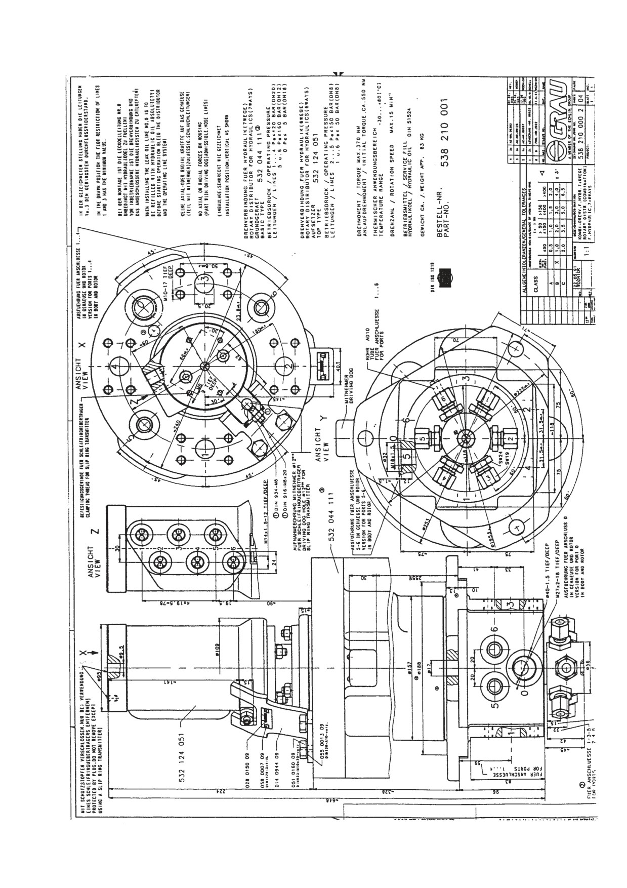
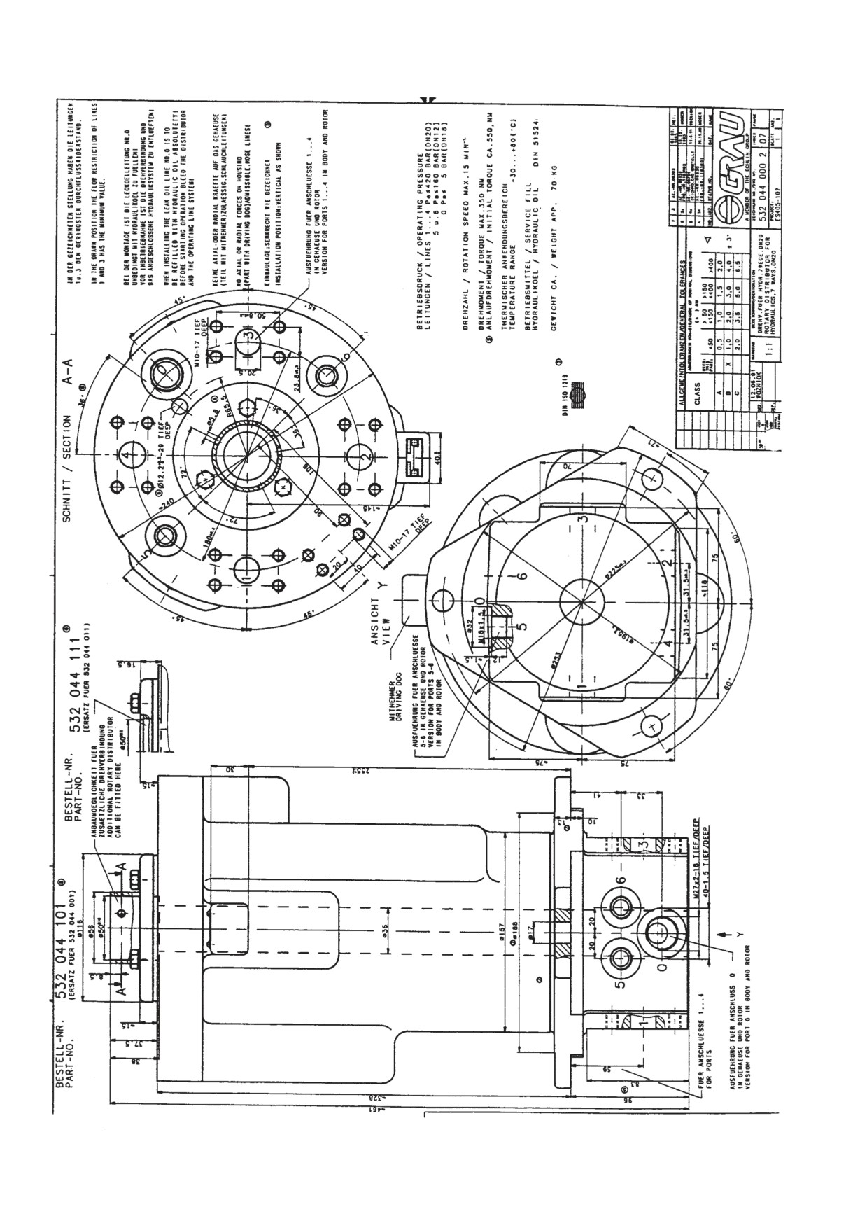
532 044 001
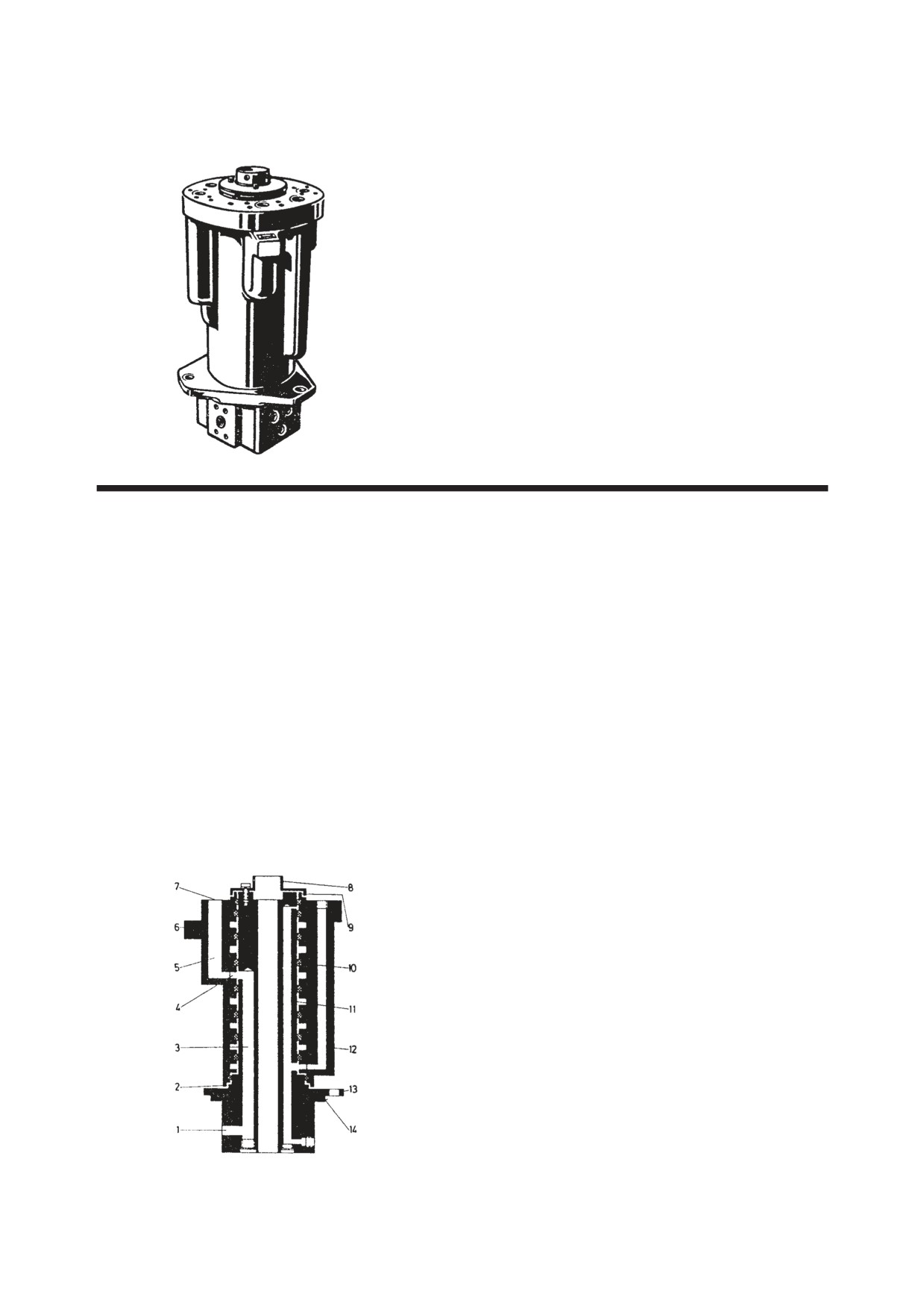
7-way swivel joint for hydrau-
lic applications
Application
The introduction of dust and spray interferes with labyrinths
As rotating line connector for introducing hydraulic fluid
9 and 2 at the interface between housing 12 and rotor 11.
from at-rest to rotating machine parts. Example: in hydrau-
lic excavators to transfer energy from the rotatable upper
Cover 8 has a seat for fitting a rotating connector. This
assembly with pumps and control blocks to the lower
makes it possible to introduce hydraulic and compressed air
assembly with hydraulic motors for driving and hydrostatic
with a perfect separation of media within the swivel joint.
linkages.
Installation instructions
Other applications upon request.
The swivel joint is attached to flange 13 with adapter 14 and
fastened with three M16 bolts. The line connectors can then
Principles of operation
attach to the tubes.
Rotor 11 in housing 12 is maintained in the axial direction
by cover 8. Channels 5 run from connectors 7 on the upper
In the housing, there should be adequate play between
side of the housing to toroidal chambers 4 which are sealed
connector 6 and the fork. Line connectors must be flexible,
from each other by special gaskets 10. Each toroidal cham-
i.e., hoses. Additional sideways loads on the swivel joint
ber 4 is connected to a radial connector 1 in rotor 11 by an
must be avoided.
axial bore 3.
Slight leakage is possible between toroidal chambers when
no pressure is present. This drains away in a common
leakage channel. If the hydraulic circuits are separate, a
common oil container will be needed.
TB175W
4
REV. 1
INSTALLATION INSTRUCTIONS
532 044 001
The oil which leaks provides continuous lubrication for the
bearing between the rotor and the housing and must be filled
with oil before start-up. The swivel joint is installed verti-
cally, with the axial connectors facing upwards. Contact the
company for information on horizontal installation.
Warning!
During assembly, the oil line (no. 0) must be filled with
hydraulic oil.
The swivel joint and the attached hydraulic system must be
bled before start-up.
Service
If the operating instructions in the installation drawings are
observed, no maintenance will be necessary.
Installation drawing
532 044 000 2
These installation instructions correspond to the present state of knowledge and are subject to revision. Grau accepts no
responsibility for application beyond those covered n these installation instructions. Special consultation is required in these
cases.
Changes in accordance with technical progress are reserved. Changes, even with our consent, must be authorized by our
modification department.
REV. 1
5
TB175W
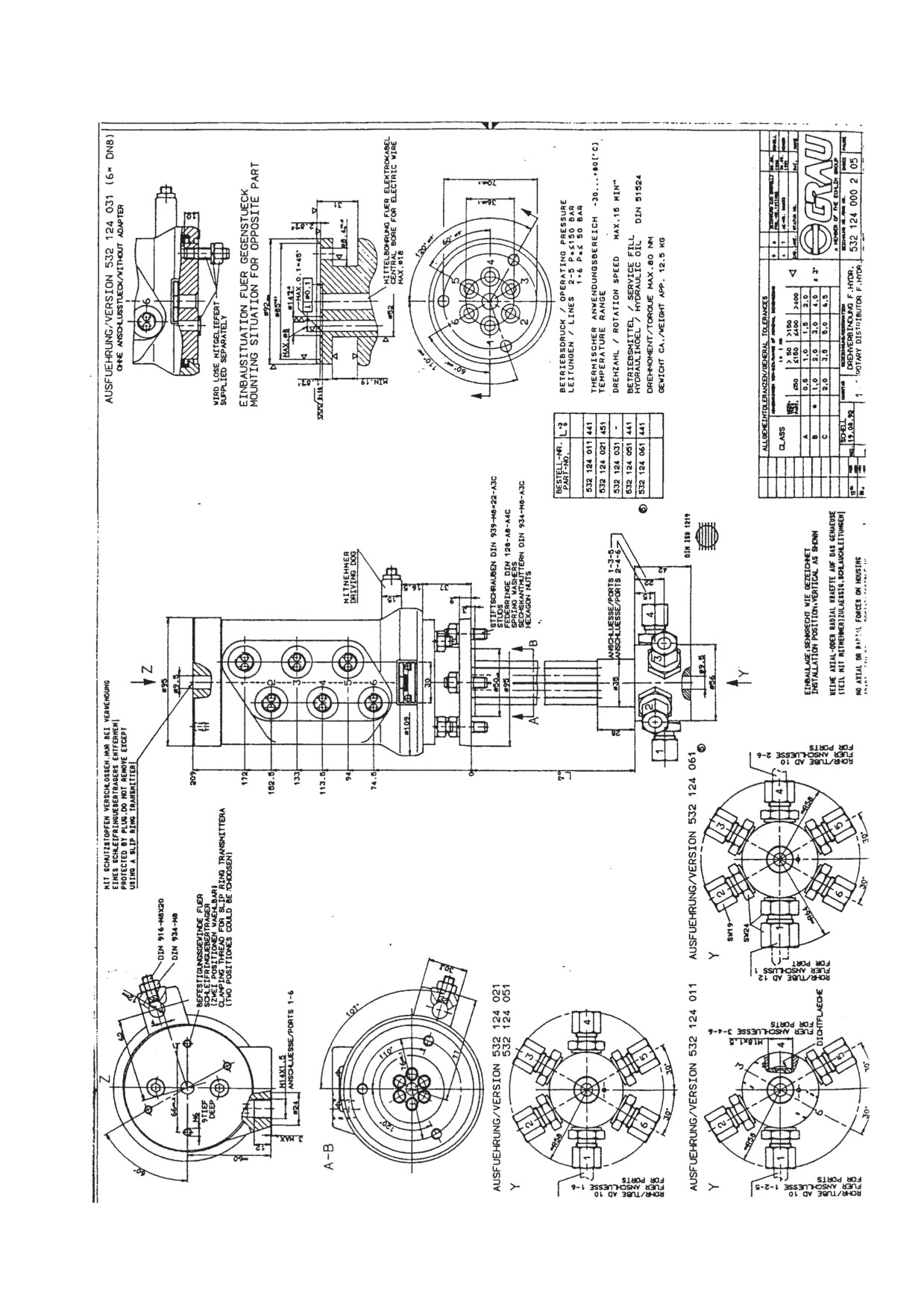
APPLICATION
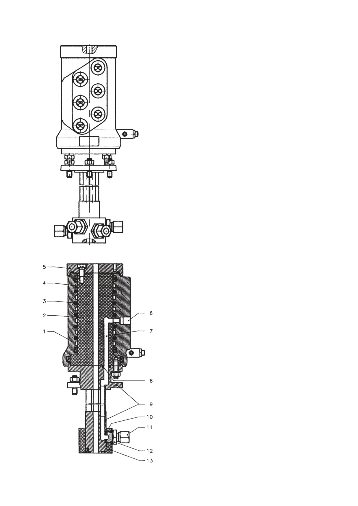
As swivel joint between moving and rotating machine parts.
Use preferably as part of a Grau combination swivel joint for
independent support of different circuits such as work and pre-control
hydraulics.
Some designs have a central bore for a cable. In these cases, fixing threads
are located in the cover for a slip ring mount.
OPERATION
The rotatable bearing supported rotor 2 in the housing is held in the
axial plane by cover 5.
Connectors 6 in the housing are connected by toroidal chambers 4,
axial bores 7 and intermediate piece 9 to connectors 11 in the
connector unit.
There is a seal between toroidal chambers 4 by means of gaskets 3, by
gaskets 8 between rotor 2 and intermediate piece 9, and by gaskets 10
between rotor 10 and connector 13.
TB175W
6
REV. 1
INSTALLATION INSTRUCTIONS
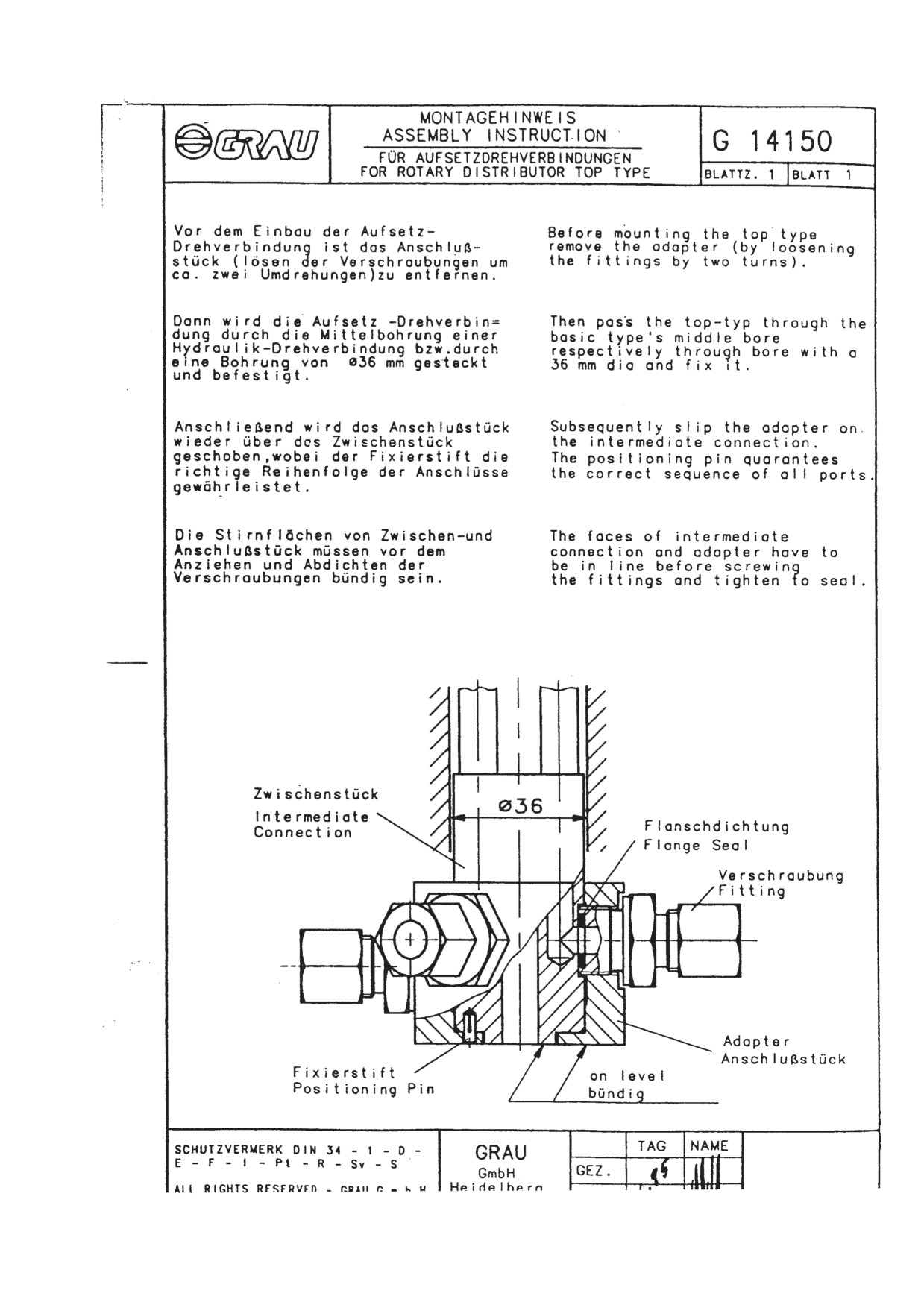
Before mounting the swivel joint on a Grau swivel joint for hydraulic applications, connector 13 must be removed by loosening
bolts 12 (by about 2 turns). The swivel joint mount is then placed with intermediate piece 9 through the central bore of the swivel
joint for hydraulic applications and fastened with the flange bolts.
Finally, connector 13 is slid with seals held in place by bolts 12 over the protruding intermediate piece 9, with the locator pin
sitting in the correct position in the connector.
Bolts 12 are tightened again to secure connector piece 13 and to seal the connectors.
Make sure there is sufficient play between the housing mount and the counter-piece.
There must be no tension when the tubes are connected, preferably with hose connectors. Additional lateral loads on the rotating
connector induced by too short or inflexible hoses must be avoided.
MAINTENANCE
If the installation instructions are observed to the letter, no maintenance will be required.
INSTALLATION DRAWING
532 124 000 2
These installation instructions correspond to the present state of knowledge and are subject to revision. Grau accepts no
responsibility for application beyond those covered n these installation instructions. Special consultation is required in these
cases.
Changes in accordance with technical progress are reserved. Changes, even with our consent, must be authorized by our
modification department.
REV. 1
7
TB175W
TB175W
8
REV. 1
REV. 1
9
TB175W
TB175W
10
REV. 1
V . TROUBLESHOOTING
V-1
TB175W
TROUBLESHOOTINTG
CAUTIONS IN TROUBLESHOOTING AND REPAIRS
(1) Do not begin disassembling the equipment immediately just because it has broken down.
Conduct a thorough preliminary check before attempting disassembly.
a. Ask the user the following questions.
• What were the conditions when the machine broke down?
• Did anything abnormal happen before breakdown occurred?
• Are there any other places which were functioning poorly other than the part that broke
down?
• Are there any parts which have been repaired previous to the breakdown? What were
they?
• Has the same thing happened before?
b. Run the machine yourself and confirm the breakdown conditions.
• Judge whether the machine is really broken down or not following the judgment
standards.
The judgment on whether the machine has broken down may differ between individu-
als.
IMPORTANT: When running the machine, it is possible that moving the machine could
make the breakdown worse than it already is, so do not forget to ask the user if there is
anything to prevent your operating the machine.
c. Based on the information that you have gathered from the user and the information
obtained from running the machine yourself, judge the cause of the trouble. Also keep in
mind that it is difficult to reproduce the conditions of the breakdown again once the
machine has been disassembled, and early disassembly may make it impossible to
determine the true cause of the trouble. Therefore be sure to find the true cause of the
trouble before attempting disassembly.
(2) When it is thought that the trouble has more than one cause, begin investigating from the
simplest cause.
(3) Think over why the trouble could have occurred and try to correct the root cause of that
problem.
TB175W
V-2
TROUBLESHOOTINTG
CONTENTS
OVERALL MACHINE
No operations can be done
4
All operations can be done, but there is no power
5
The boom, bucket, slew and arm do not move at all, or the speed is low
7
SLEWING
No slewing can be done
9
Right or left slewing cannot be done
12
Slewing speed is low, or there is no power
14
The machine slews, but overrun when slewing stops is great, or it cannot be stopped
16
Slewing in slow gear is not possible
18
BOOM
The boom cylinder doesn’t move
20
Boom cylinder operation is slow, or there is no power
22
When the boom operation lever is pulled gently, the boom drops temporarily
25
The amount of boom natural drop is great
26
The boom adjustment cylinder doesn’t move
27
ARM
The arm cylinder doesn’t move
30
Arm cylinder operation is slow, or there is no power
32
The amount of arm natural drop is great
34
BUCKET
The bucket cylinder doesn’t move, or there is no power
35
The amount of bucket natural drop is great
37
BOOM SWING
The swing cylinder doesn’t move
38
V-3
TB175W
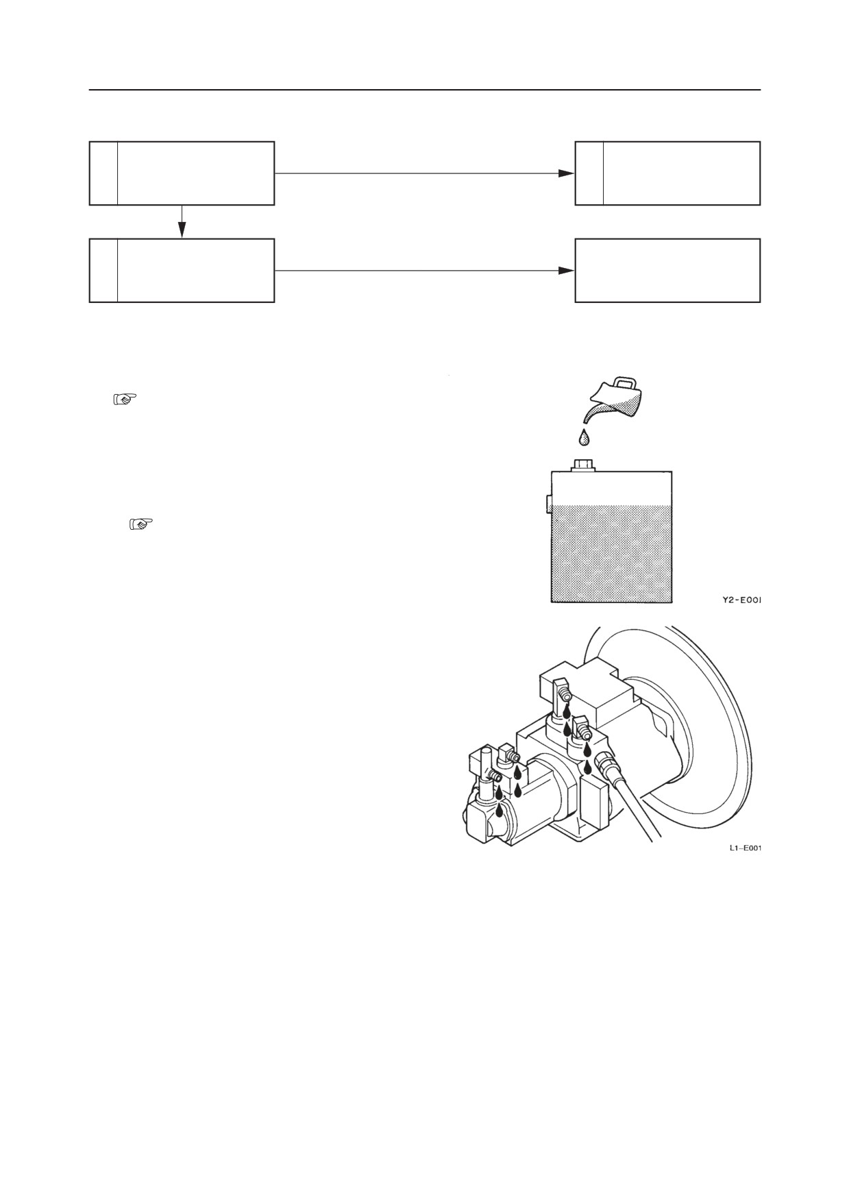
TROUBLESHOOTINTG
OVERALL MACHINE
NO OPERATIONS CAN BE DONE.
Inspect the hydraulic oil
Insufficient
Replenish the hydraulic
1
2
level.
oil.
Proper Amount
• Repair the pump or replace
Pump or coupling is
3
the pump.
faulty.
• Replace the coupling.
1. Inspect the hydraulic oil level.
“III. Machine Configuration, Hydraulic
Tank”
2. Replenish the hydraulic oil.
Take out the plug and replenish the hydraulic oil.
• The hydraulic oil supplied should be the same
brand as the oil currently in the tank.
“II. Specifications, Fluid Capacities”
3. Pump or coupling is faulty.
a. Disconnect the discharge hose from the pump
side.
Also fit a plug in the disconnected hose to keep
the hydraulic oil from pouring out.
b. With the engine emergency stop knob pulled
out all the way, turn the start switch to the
“START” position to cause the engine to begin
cranking. Check that the hydraulic oil is dis-
charged from the pump at this time.
If the pump is normal, hydraulic oil will be
discharged from it. If hydraulic oil is not dis-
charged, the pump or the coupling is faulty.
TB175W
V-4
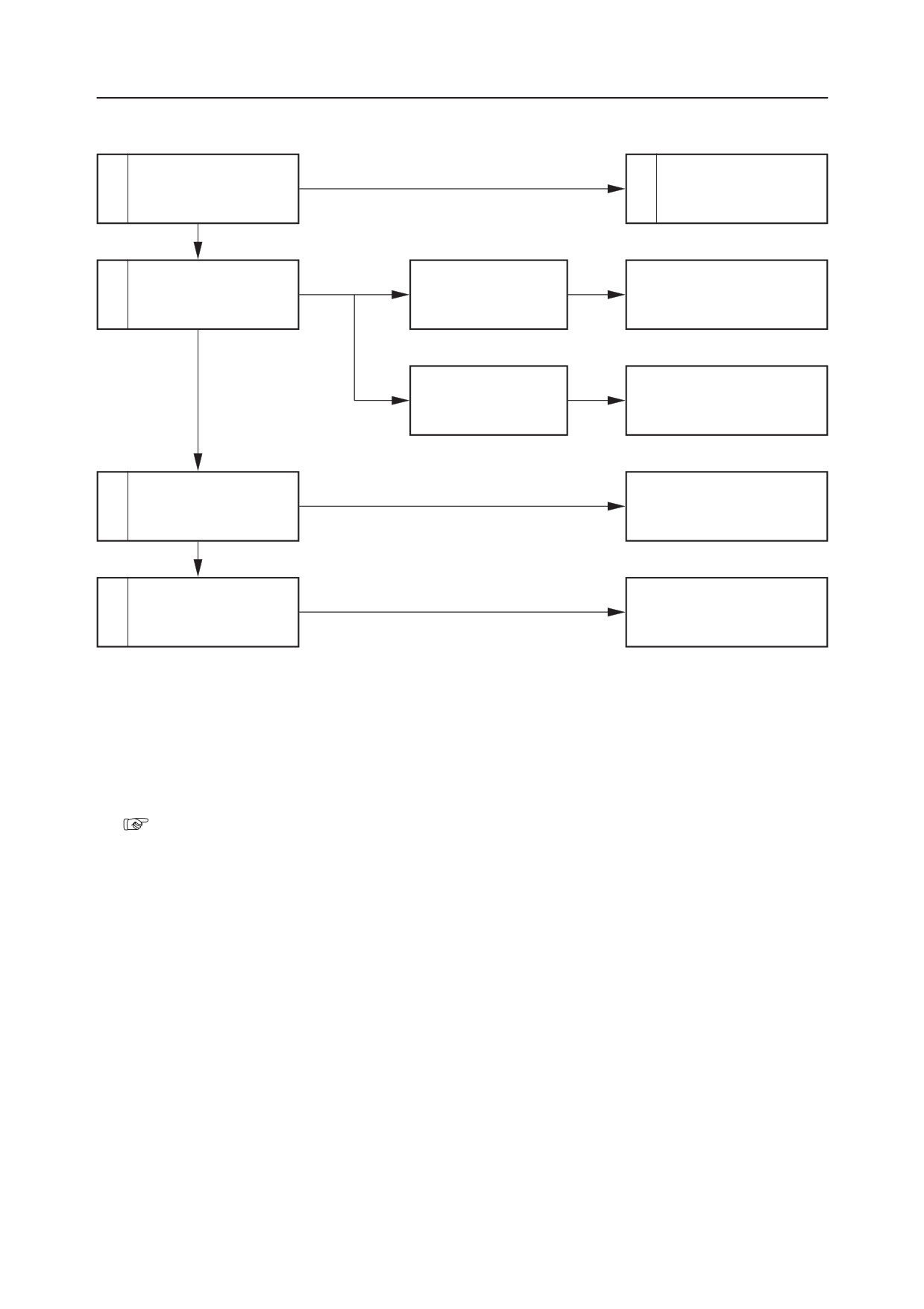
OVERALL MACHINE
TROUBLESHOOTINTG
ALL OPERATIONS CAN BE DONE, BUT THERE IS NO POWER.
Inspect the hydraulic oil
Insufficient
Replenish the hydraulic
1
2
level.
oil.
Proper Amount
Noise generated by the
Noise
Replace the seal tape, O-rings,
3
Suction line is faulty.
pump.
hose.
No Noise
Bubbles from inside
Treat beginning at the source
the tank.
of the bubbling.
Faulty
Inspect the main relief
Repair or replace the main
4
valve.
relief valve.
Normal
• Repair or replace the pump.
5
Pump is faulty.
• Flush with hydraulic oil.
1. Inspect the hydraulic oil level.
2. Replenish the hydraulic oil.
“V-4”
3. Noise generated by the pump.
A faulty suction line can make it easy for cavita-
tion to occur in the pump and for noise to be
generated. Carry out the following inspect.
a. Inspect the piping used for suction of hydraulic
oil.
• Apply grease or oil to the part which appears
to be making the noise and inspect if there is
any change. (Inspect if it is sucking in air or
not.)
b. Inspect for clogging of the suction filter.
V-5
TB175W
TROUBLESHOOTINTG
OVERALL MACHINE
4.
Inspect the main relief valve.
Measure the relief pressure of the main relief
valve.
• The valve is normal if the pressure gauge
reading is the standard value.
“ II. Specifications, Standards for Judging
Performance”
If the main relief valve’s set pressure is too low,
adjust it by tightening the valve set screw gradu-
ally.
“II. Specifications, Standards for Judging
Performance”
5.
Pump is faulty.
If the pump is abnormally worn internally, or if it
is damaged, it is possible that pieces of metal are
mixed into the hydraulic oil. Therefore, carry out
the following treatment.
• Replace the spin filter cartridge.
• Replace the hydraulic oil or flush out the
hydraulic circuit.
(Up to NAS Class 9)
Caution : When replacing the hydraulic oil, be
sure to clean the inside of the Hydraulic Tank and
the suction strainer.
If the pump seal is damaged, replace the seal.
“IV. Hydraulic Units, Hydraulic Pump”
TB175W
V-6
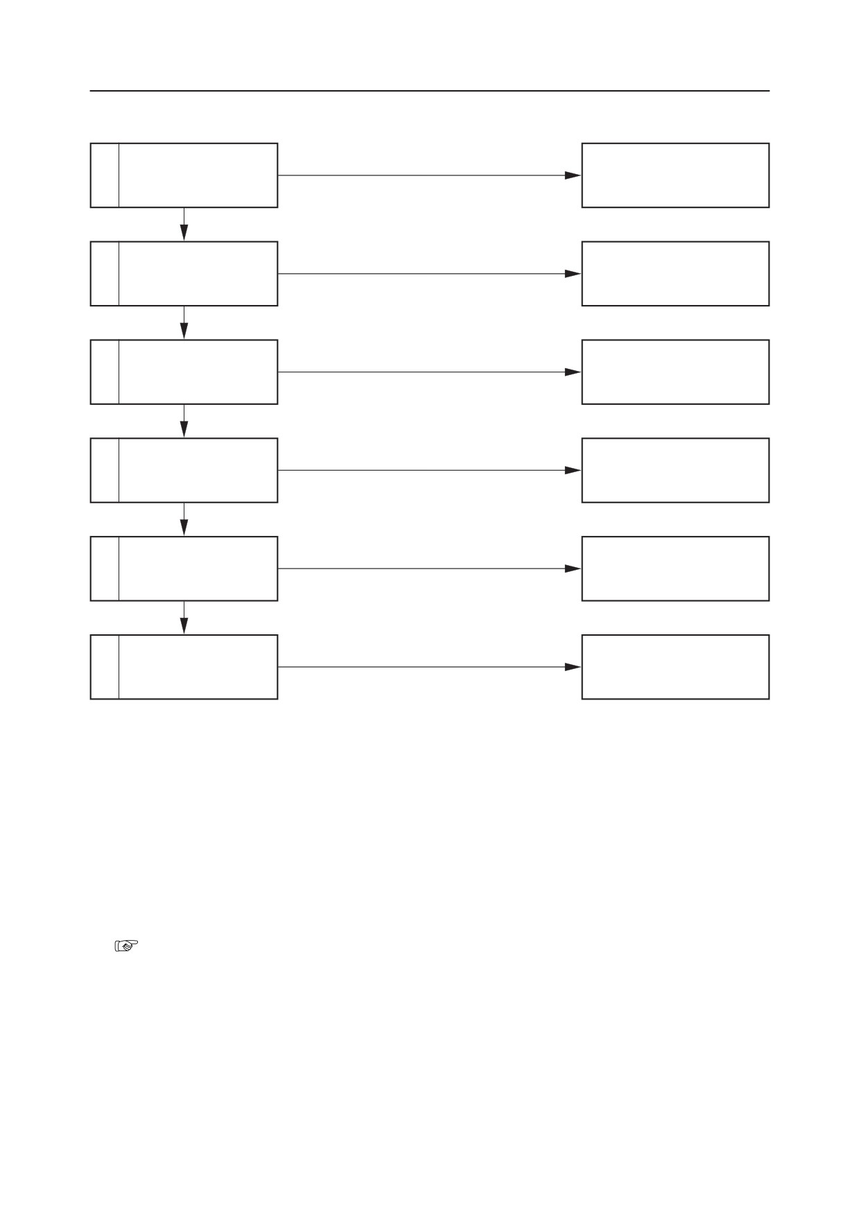
OVERALL MACHINE
TROUBLESHOOTINTG
THE BOOM, BUCKET, SLEW AND ARM DO NOT MOVE AT ALL, OR THE SPEED IS LOW.
Inspect the hydraulic
Faulty
Repair or replace the hydrau-
1
pump P5.
lic pump P5.
Normal
Faulty
2
Inspect the fuse.
Replace the fuse.
Normal
Faulty
Adjust or replace the limit
3
Inspect the limit switch.
switch.
Normal
Inspect the lever lock so-
Faulty
Repair or replace the lever lock
4
lenoid valve.
solenoid valve.
Normal
Inspect the pilot relief
Faulty
Adjust, repair or replace the
5
valve.
pilot relief valve.
Normal
Faulty
Repair or replace the pilot
6
Inspect the pilot valve.
valve.
1. Inspect the hydraulic pump P5.
Inspect the hydraulic pump P5 which is the source
of the hydraulic pressure for the pilot valve.
“V-4”
Since clogging of the line filter can also be con-
sidered, inspect and clean the filter.
V-7
TB175W
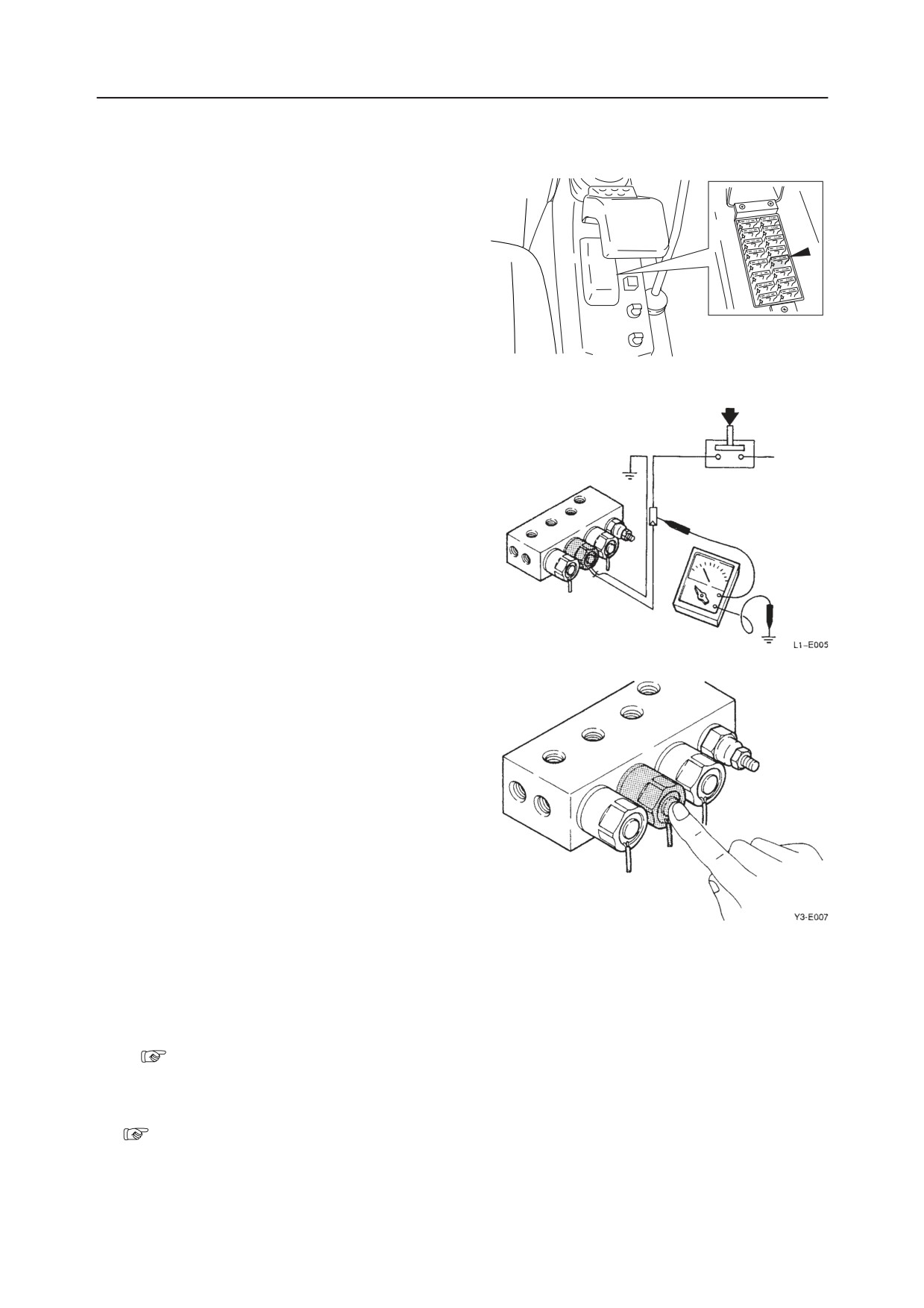
TROUBLESHOOTINTG
OVERALL MACHINE
2. Inspect the fuse.
Inspect the fuse for the electric power circuit that
operates the pilot solenoid valve.
W2E003
3. Inspect the limit switch.
Set the lever stand to the operation position to turn
on the limit switch. Check the voltage at the lever
lock solenoid valve by using a tester.
• The limit switch is normal if the voltage is
being applied.
Reference: If the limit switch is found to be faulty
and the attachment must be moved, connect the
lever lock release connectors (male) and (female)
for emergency use.
4. Inspect the lever lock solenoid valve.
Inspect by the following procedure.
a. Turn the starter switch to the “ON” position.
b. Push lightly on the projection on the front end
of the solenoid valve.
c. Move the lever stand and change the limit
switch from “OFF” to “ON”.
d. If the spool moves and vibration can be felt
with the fingertip when the circuit changes,
then it is normal.
5. Inspect the pilot relief valve.
Measure the relief pressure of the pilot relief
valve.
• If the pressure is the standard value, the valve
is normal.
“II. Specifications, Standards for Judging
Performance”
6. Inspect the pilot valve.
“IV. Hydraulic Units, Pilot Valve”
TB175W
V-8
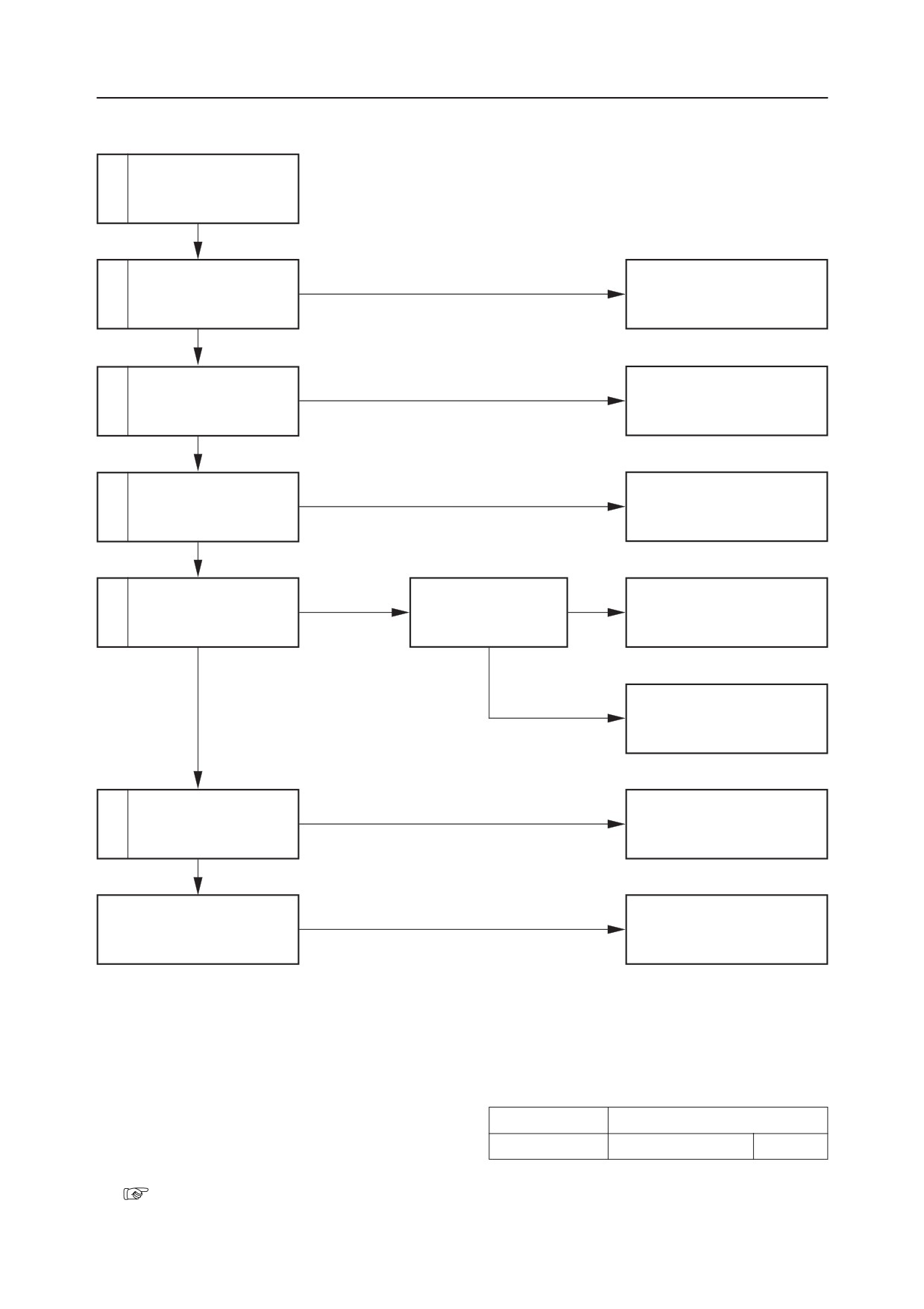
SLEWING
TROUBLESHOOTINTG
NO SLEWING CAN BE DONE.
Inspect the operation of
1
actuators other than the
slew motor.
Normal
Faulty
Repair or replace the pilot
2
Inspect the pilot valve.
valve.
Normal
Faulty
Repair or replace the shuttle
3
Inspect the shuttle valve.
valve.
Normal
Faulty
Inspect the operation of
Repair or replace the housing
4
the spool.
block.
Normal
Inspect the slew hydrau-
Pressure is low.
Adjust the slew relief
5
Adjust the set pressure.
lic pressure.
valve pressure.
Normal
Pressure does not rise
Repair or replace the slew re-
lief valve.
Faulty
Repair or replace the slew
6
Inspect the slew motor.
motor.
Normal
The slew bearing is faulty.
Replace.
1. Inspect the operation of actuators other than
the slew motor.
Inspect if the operation of the slew motor only is
Lever Operated
Places inspected
faulty by the table at right. If its operation is
Dozer Blade
Relief Valve R3
Pump P3
faulty, inspect the main relief valve and the hy-
draulic pump.
“V-6”
V-9
TB175W
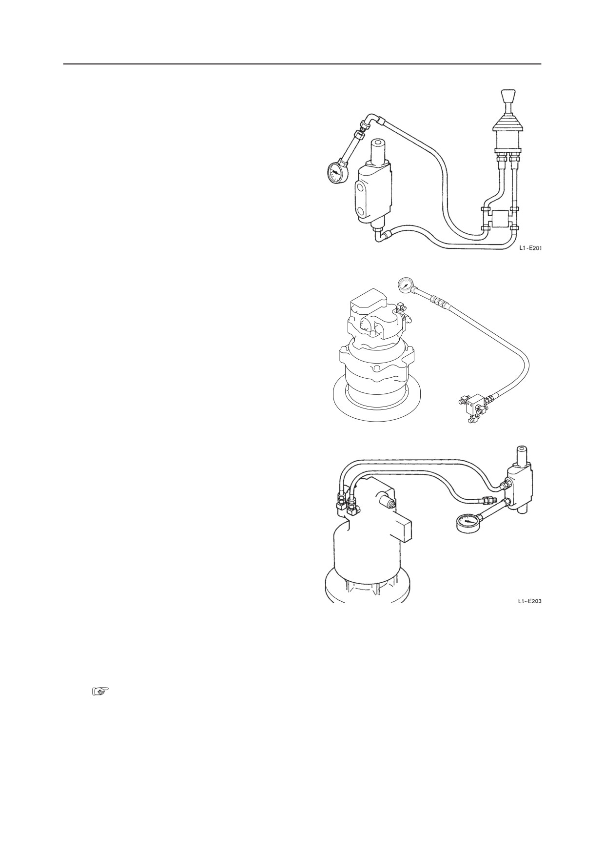
TROUBLESHOOTINTG
SLEWING
2. Inspect the pilot valve.
Disconnect the hose between the pilot valve and
control valve (slew section) at the control valve
side, then set a pressure gauge in the disconnected
hose.
• A plug should be inserted in the control valve
port.
• Operate the lever (slew) and measure the pres-
sure.
• Depending on the operating angle, a pressure
in the 0~3.4 MPa range is normal.
3. Inspect the shuttle valve.
Disconnect the hose that goes between the shuttle
valve and the slew motor at the slew motor side
and set a pressure gauge to the disconnected hose.
• Operate the lever (slew) and measure the pres-
sure.
• The shuttle valve is normal if between 0 and
3.4 MPa corresponding to the operation angle.
4. Inspect the operation of the spool.
Disconnect the hose that goes between the control
valve (slew section) and the slew motor at the
valve side and set a pressure gauge to the dis-
charge port of the valve.
• Operate the lever (slew) and measure the pres-
sure.
• The operation of the spool is normal if it agrees
with the following value of supply pressure:
23.5 MPa
5. Inspect the slew hydraulic pressure.
Measure the pressure at the left and right slew
relief valves.
• The pressure is normal if it is the standard
value.
“II. Specifications, Standards for Judging
Performance”
If adjustment of the pressure is possible, the slew
relief valve’s adjustment is faulty. Also, if the
pressure adjustment is impossible, the slew relief
valve is faulty.
TB175W
V-10
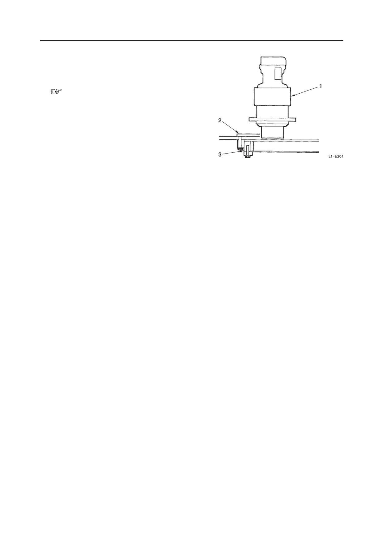
SLEWING
TROUBLESHOOTINTG
6. Inspect the slew motor.
Separate the slew motor (1) and the turntable (2),
then try turning the turntable (2).
• Turntable doesn’t turn
Faulty slew bearing (3).
• Turntable turns
Faulty slew motor (1).
“IV. Hydraulic Units, Slew Motor”
V-11
TB175W