Takeuchi Gear Box 357A10. Service Manual (1998) - page 4
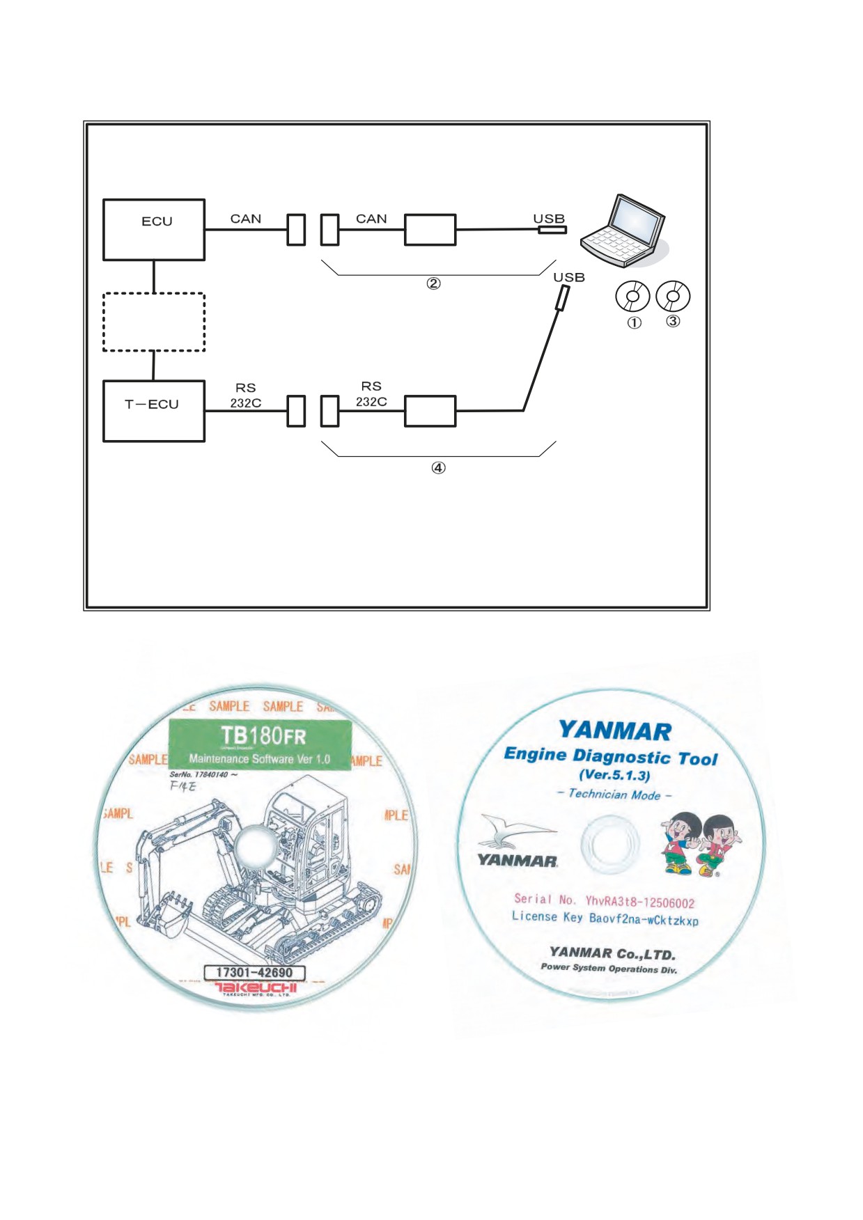
(2) Connection diagram for TB180FR
T-ECU: Takeuchi-Electrical Control Unit
Excavator
Engine model: 4TNV98T-ZNTBL
TB180FR (F14E) T-3
Compliant with Tier 3 emission standards
Serial No. 17840001 or later
Laptop computer
Interface box
(Yanmar)
Yanmar Engine Diagnostic Tool (EDT)
Engine
Configuration
ᶃ Software CD
ᶄ Interface cable
Interface box
(Takeuchi)
Takeuchi maintenance tool
Configuration
ᶅ Maintenance software CD (Part No. 17301-42690)
ᶆ Dedicated USB cable (Part No. 17301-42720)
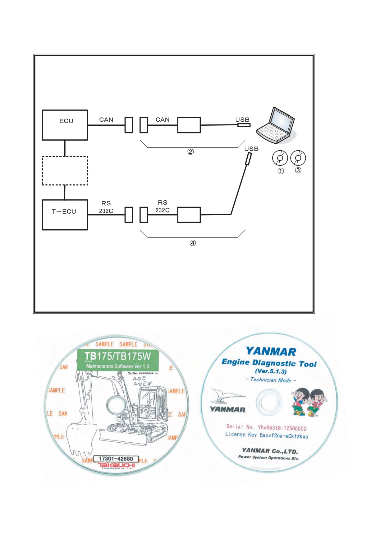
(3) Connection diagram for TB175 and TB175W
T-ECU: Takeuchi-Electrical Control Unit
Excavator
Engine model: 4TNV98T-ZNTBL
TB175 (A14E) T-3
Compliant with Tier 3 emission standards
Serial No. 17530001 or later
TB175W (A14EW) T-3
Serial No. 17540001 or later
Laptop computer
Interface box
(Yanmar)
Yanmar Engine Diagnostic
Tool (EDT)
Configuration
Engine
ᶃ Software CD
ᶄ Interface cable
Interface box
(Takeuchi)
Takeuchi maintenance tool
Configuration
ᶅ Maintenance software CD (Part No. 17301-42680)
ᶆ Dedicated USB cable (Part No. 17301-42720)
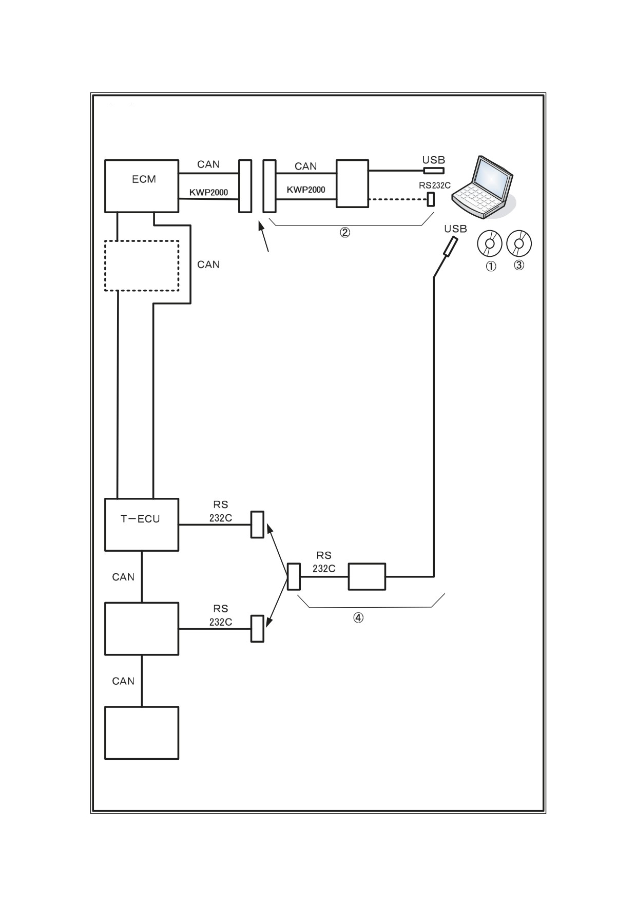
(4) Connection diagram for TB1140
T-ECU: Takeuchi-Electrical Control Unit
Excavator
Engine model: 4JJ1X (Isuzu)
TB1140 (A25C) T-3
Compliant with Tier 3 emission standards
Serial No. 514200001
or later
Selector
Laptop computer
(Isuzu)
Engine
Data link connector
Engine module programming system
(EMPS-III), Isuzu
Configuration ᶃ Software CD
ᶄ Interface cable (six types)
Refer to the EMPS manual for details.
(Takeuchi)
Interface box
Proportional ampli-
fier for the service
Connection upon selection
port (Takeuchi)
Takeuchi maintenance tool
Configuration
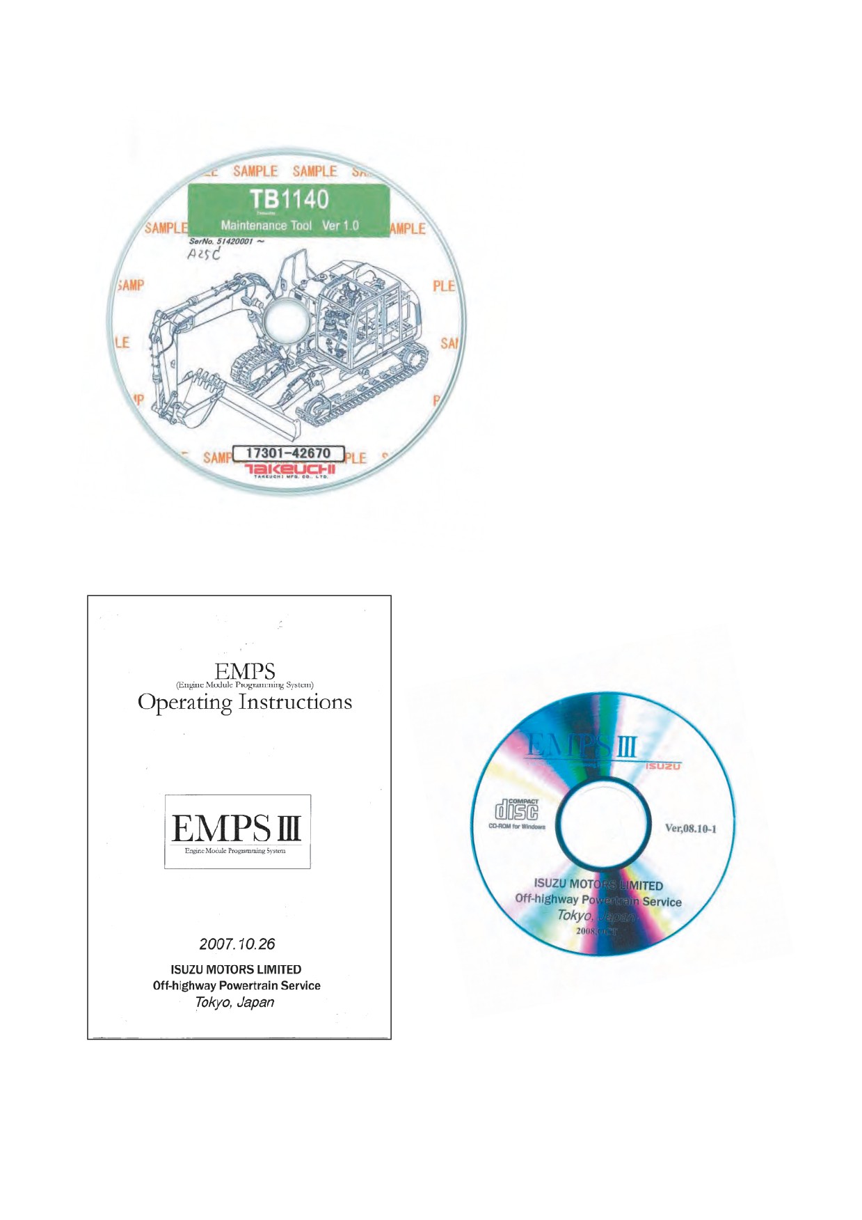
ᶅ Maintenance software CD (Part No. 17301-42670)
Cluster panel
ᶆ Dedicated USB cable (Part No. 17301-42720)
(Takeuchi)
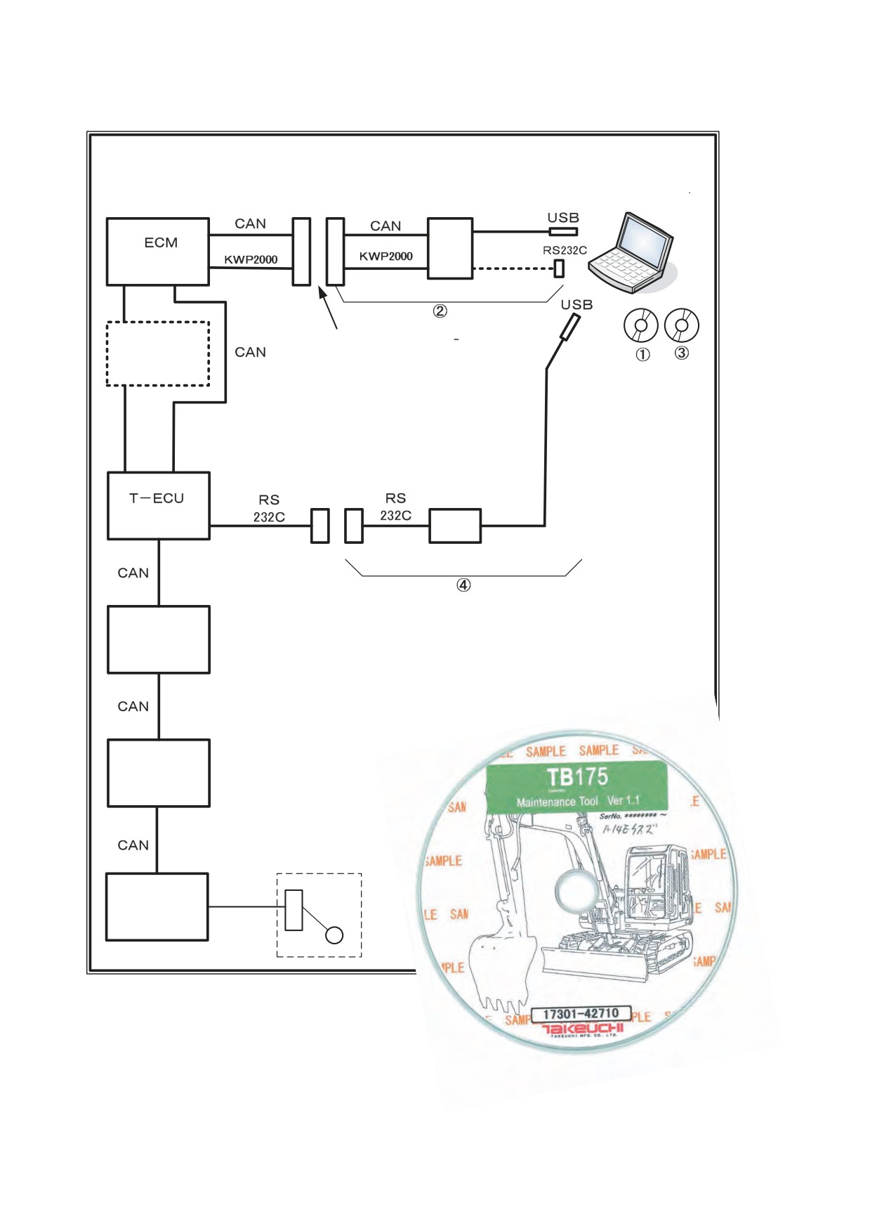
(5) Connection diagram for TB175 with an Isuzu engine
T-ECU: Takeuchi-Electrical Control Unit
Excavator
Engine model: 4JJ1X (Isuzu)
TB175 (A14E Isuzu)
Compliant with Tier 3 emission standards
Monitor machine
Laptop computer
Selector
(Isuzu)
Data link connector
Engine
Engine module programming system
(EMPS-III), Isuzu
Configuration ᶃ Software CD
ᶄ Interface cable (six types)
Refer to the EMPS manual for details.
Interface box
(Takeuchi)
Takeuchi maintenance tool
Proportional ampli-
Configuration
fier for the service
ᶅ Maintenance software CD (Part No. 17301-42710)
port (Takeuchi)
ᶆ Dedicated USB cable (Part No. 17301-42720)
Cluster panel
(Takeuchi)
Fuel tank
Fuel sender
CAN unit
(Takeuchi)
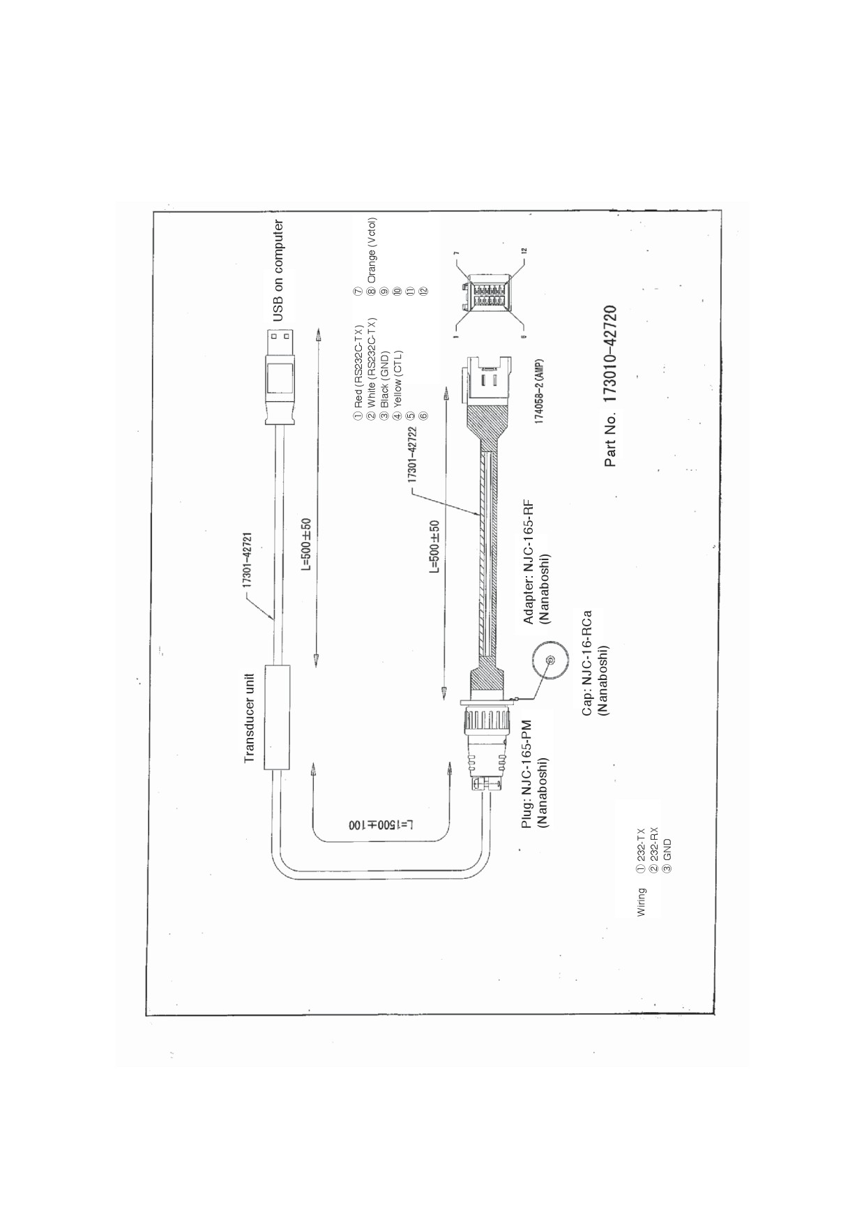
Dedicated USB cable connecting the computer and the connector on the machine
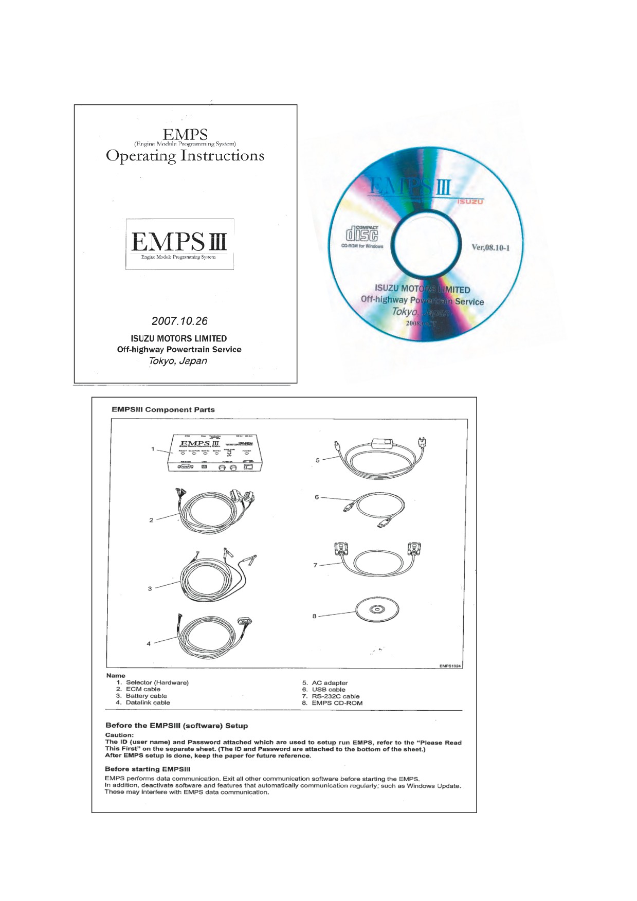
Isuzu Engine Maintenance tool
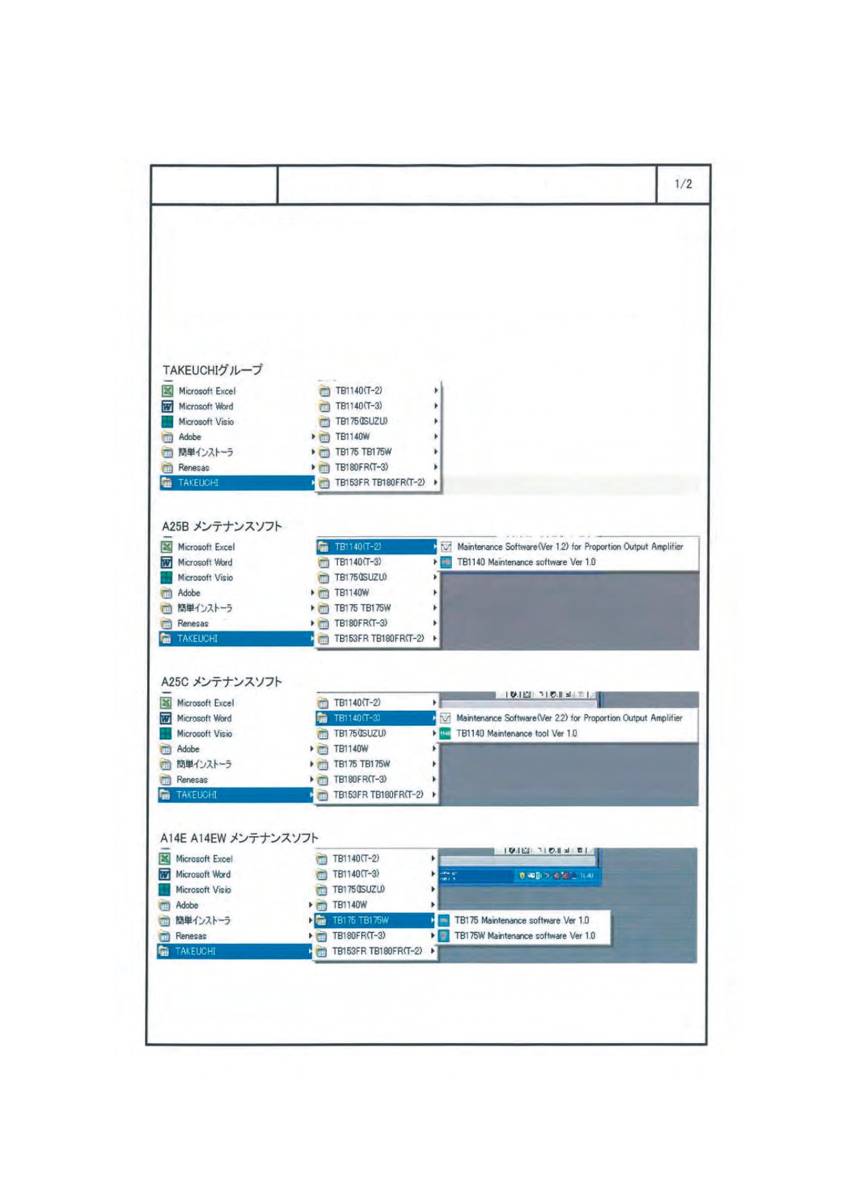
4. Computer screen after software installation
Model
Start menu 1
Maintenance software
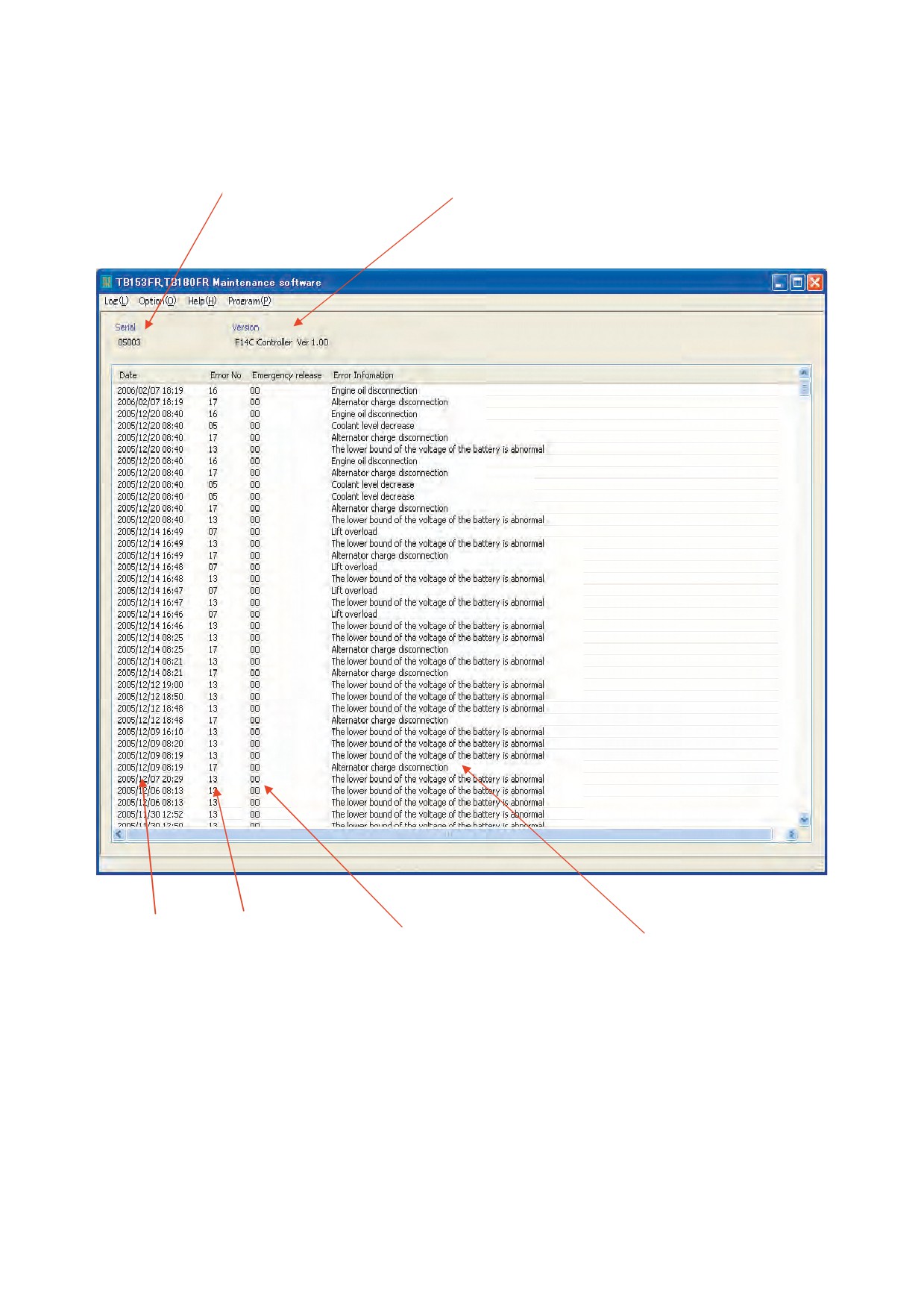
Start menu configuration
The start menu configuration of maintenance software after installation is
illustrated as follows.
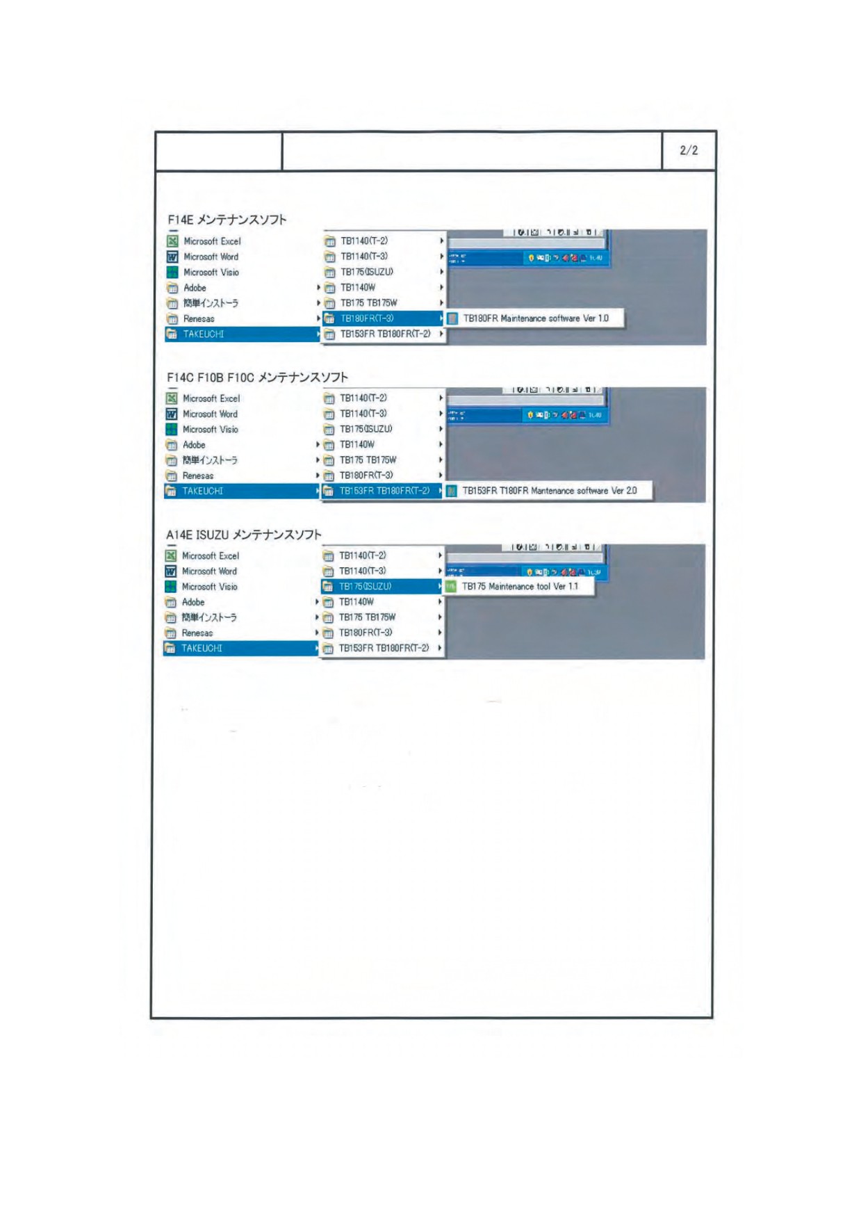
Model
Start menu 2
Maintenance software
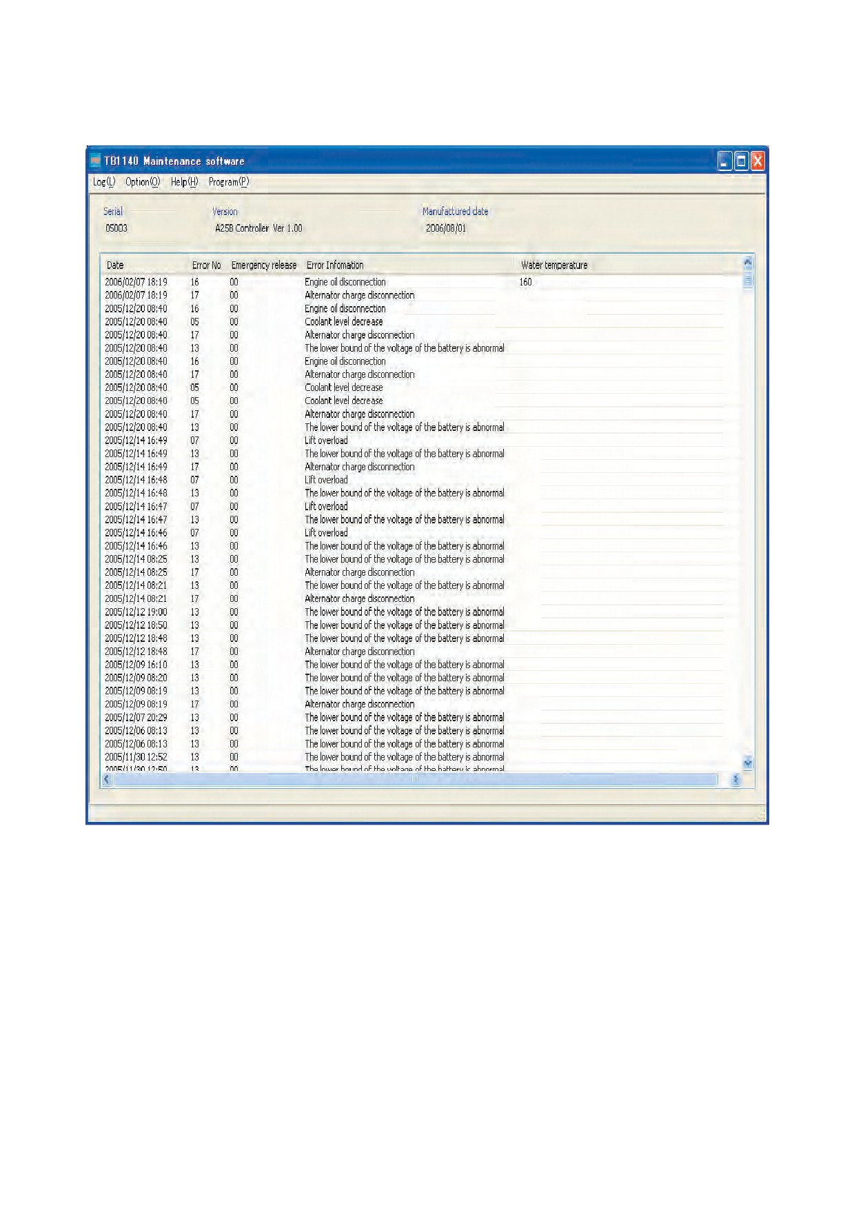
5. Maintenance software for F14C, F10C and F10B executed
T-ECU serial number
Version of the software installed
Date and time the
Error code
State of the emergency re-
error occurred
Display of errors or abnormal
lease
states
00: Off
01: On
If the “01” state is displayed
when the engine is overheat-
ing or seizing, it indicates that
the emergency release has
been turned on to force en-
gine operation. (It is not due
to a defect in the machine.)
6. Maintenance software for A25B and A25D executed
(1) Maintenance software is selected
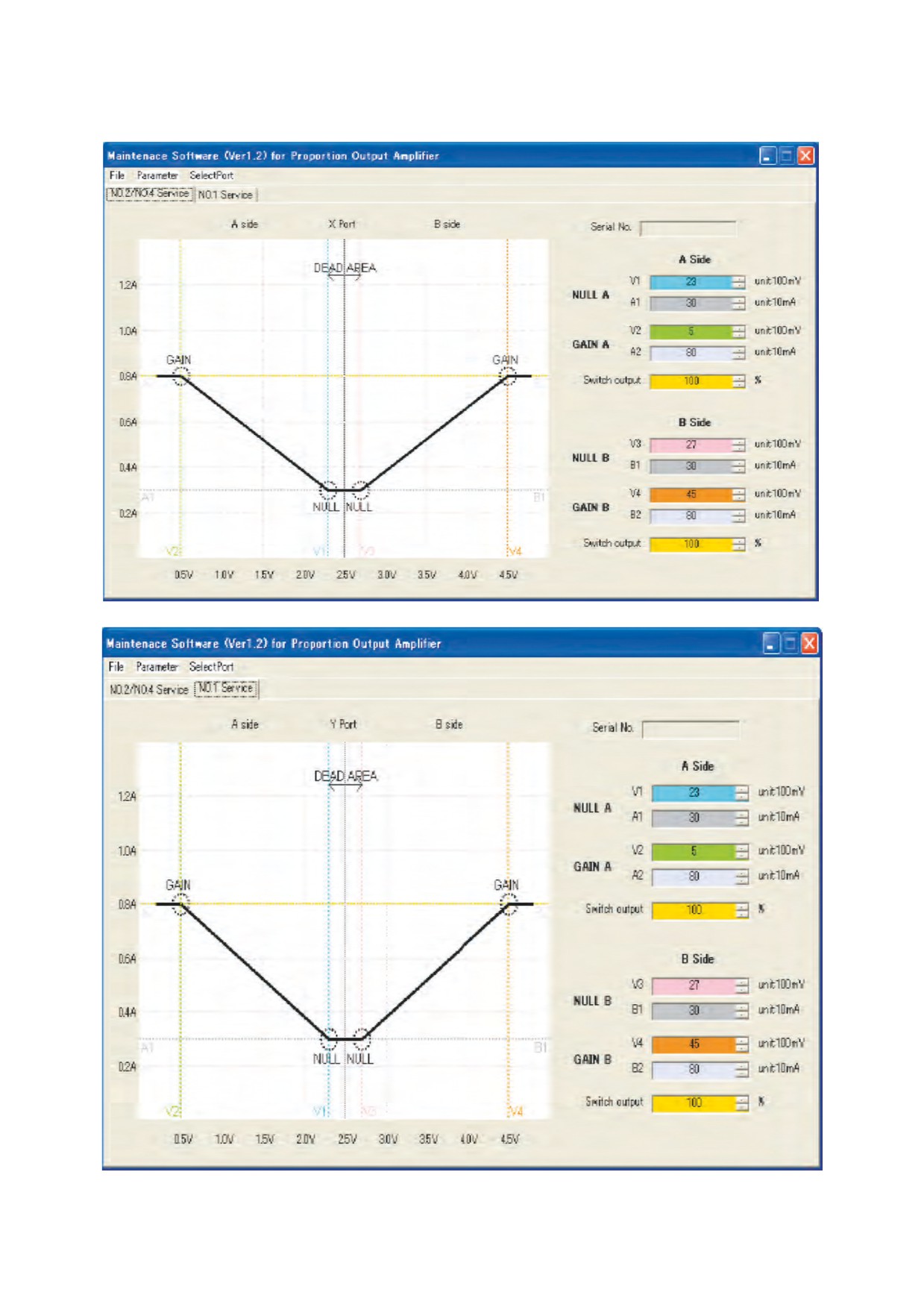
(2) A25B and A25D Maintenance Software for Proportion Output Amplifier (Refer to each manual for further
information.)
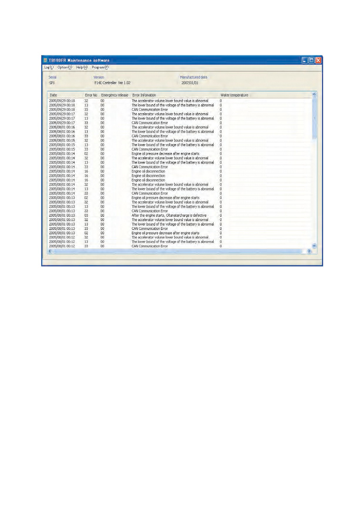
7. F14E maintenance software executed
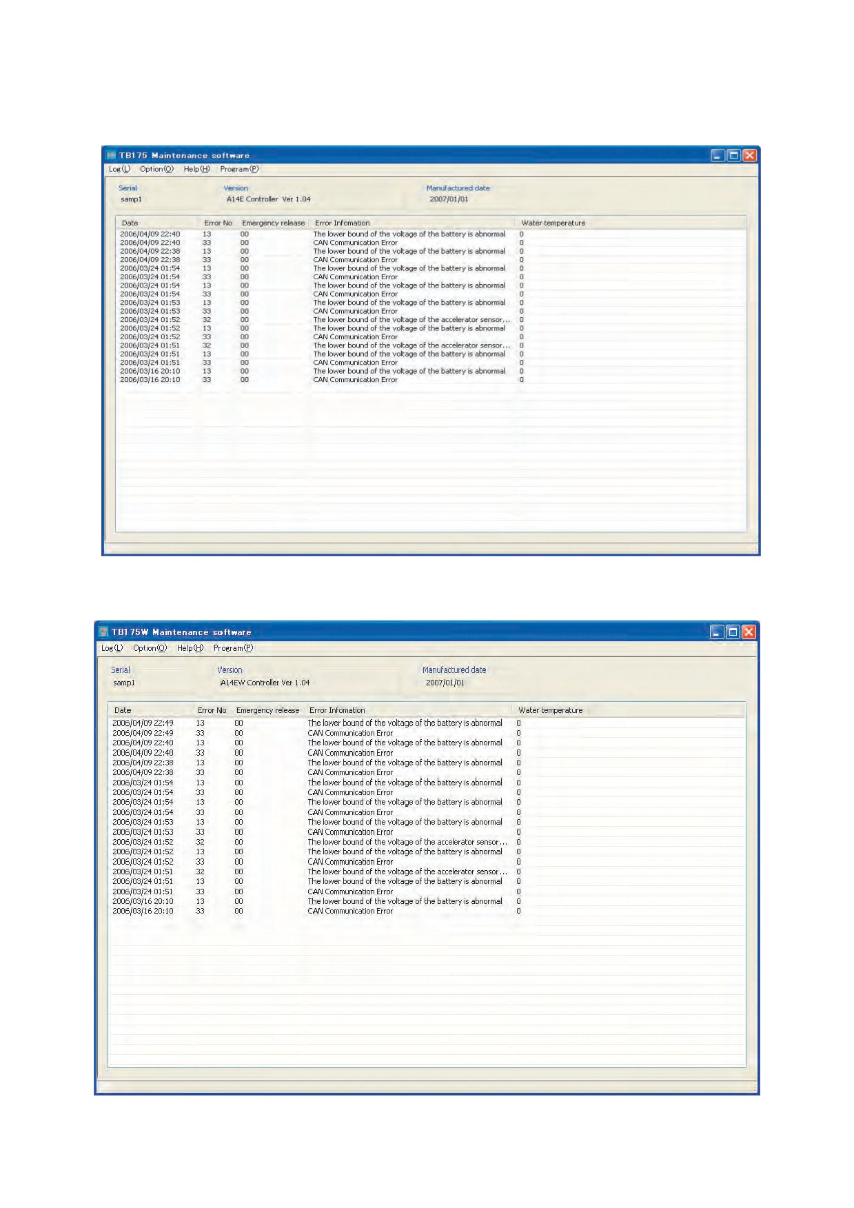
8. A14E and A14EW maintenance software executed
(1) A14E Maintenance software is selected
(2) A14EW Maintenance software is selected
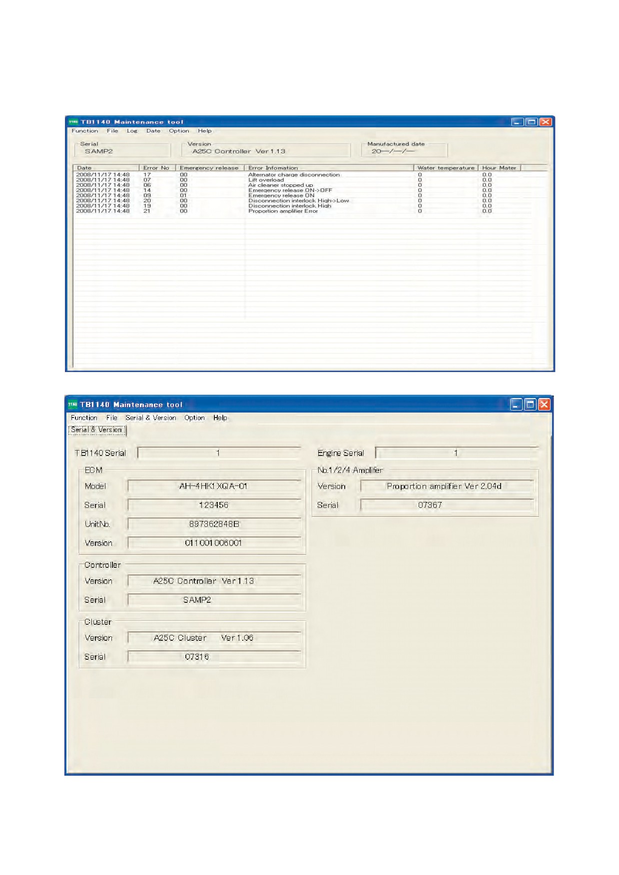
9. A25C maintenance software executed
(1) Maintenance software is selected
(2) Management software is selected
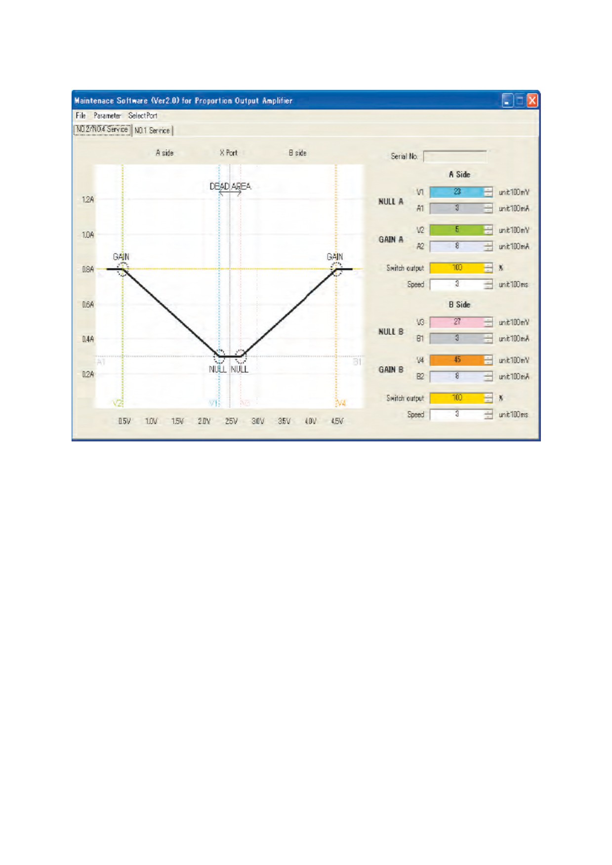
(3) Maintenance Software for Proportion Output Amplifier is selected
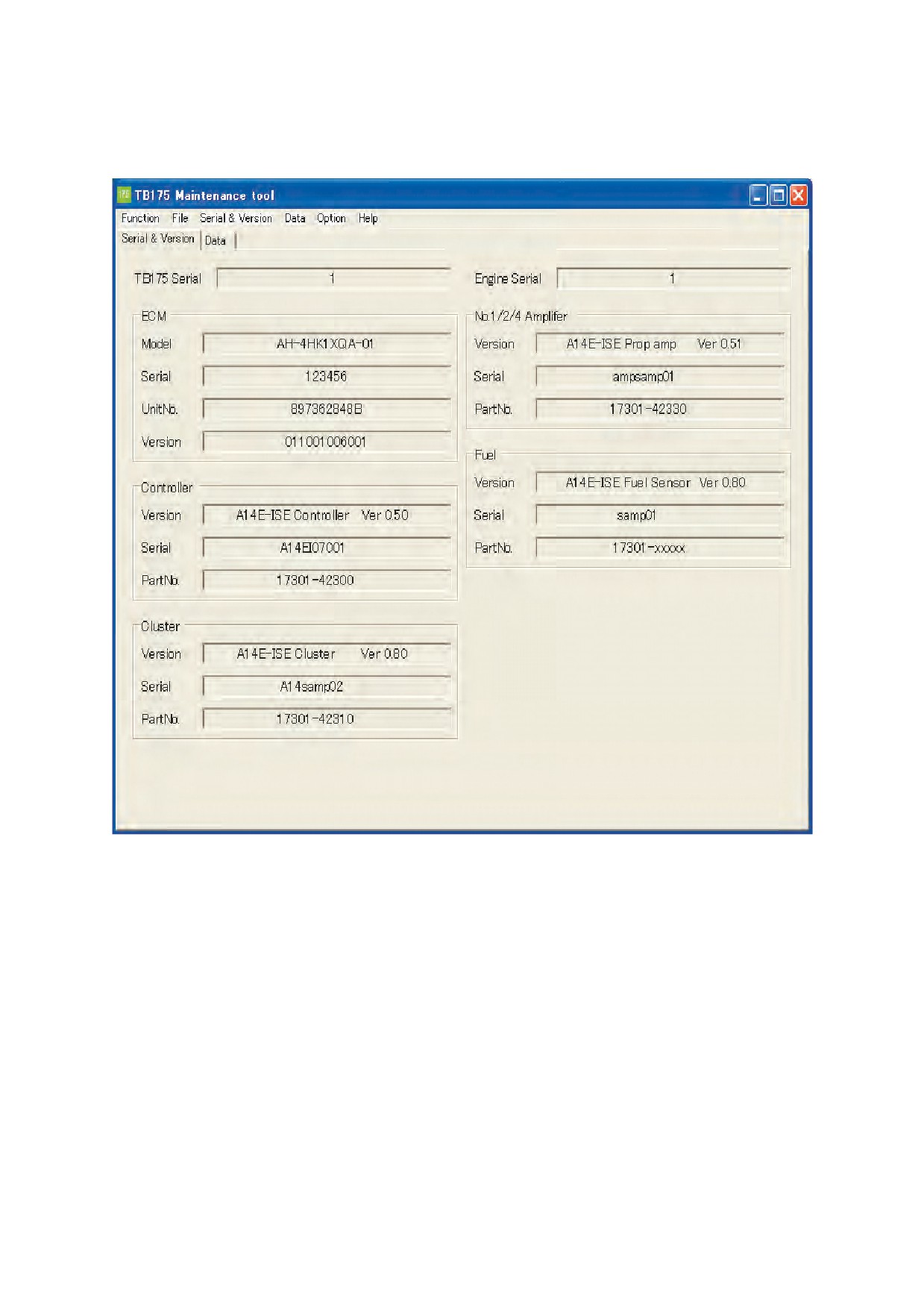
10. Maintenance tool executed on the A14E Isuzu monitor machine
(1) Management software is selected.
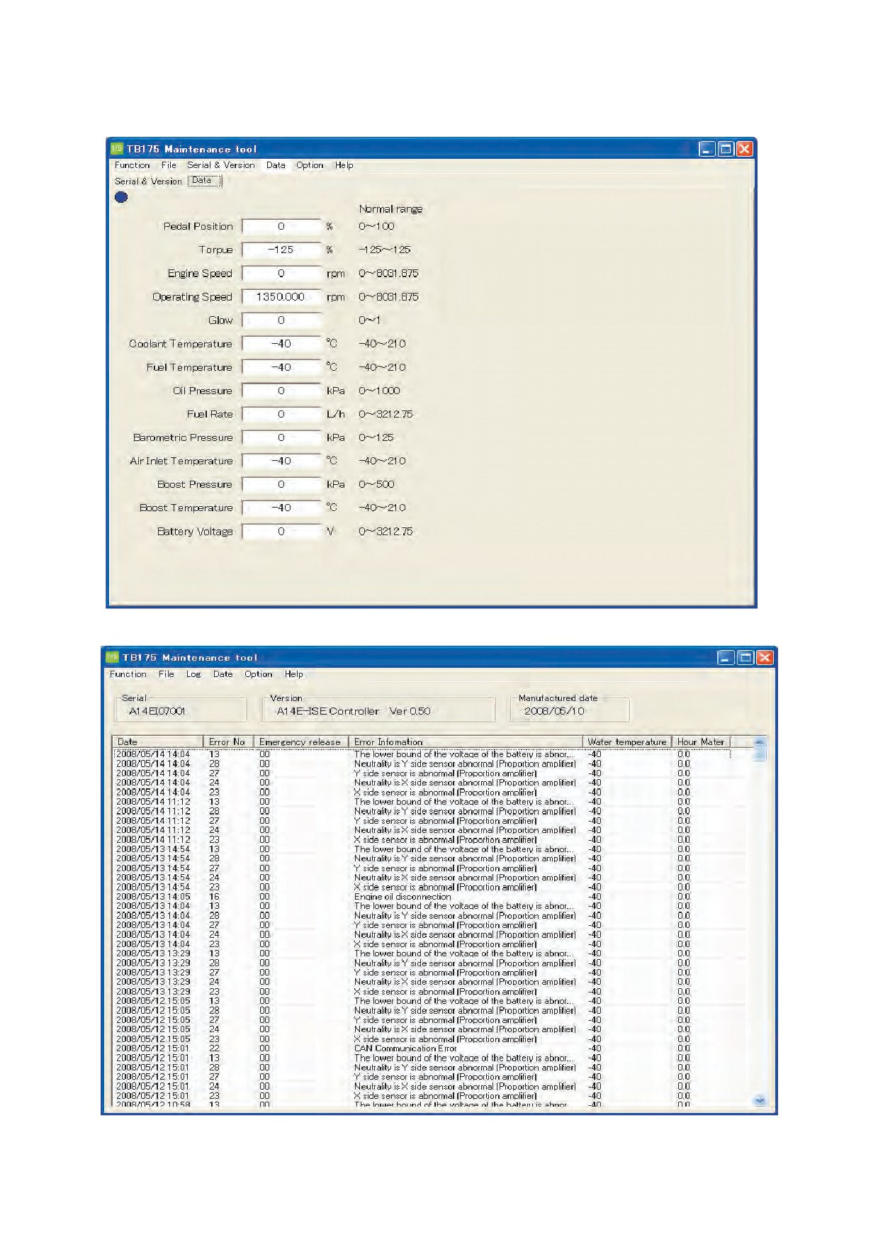
(2) ECM data browse is selected
(3) Management software is selected
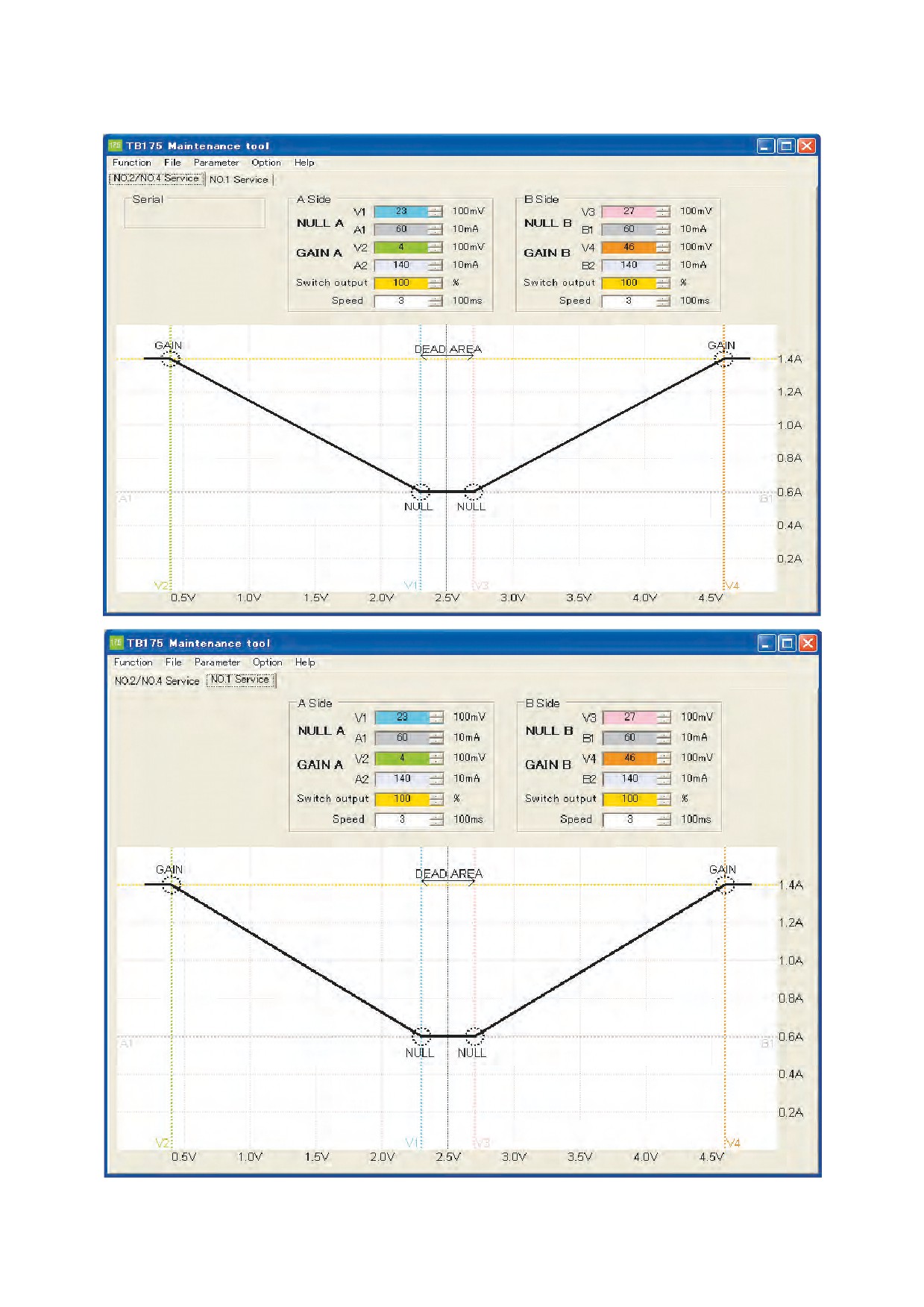
(4) Maintenance Software for Proportion Output Amplifier is selected
TB175W Maintenance software Ver1.0
SerNO. 17540001~
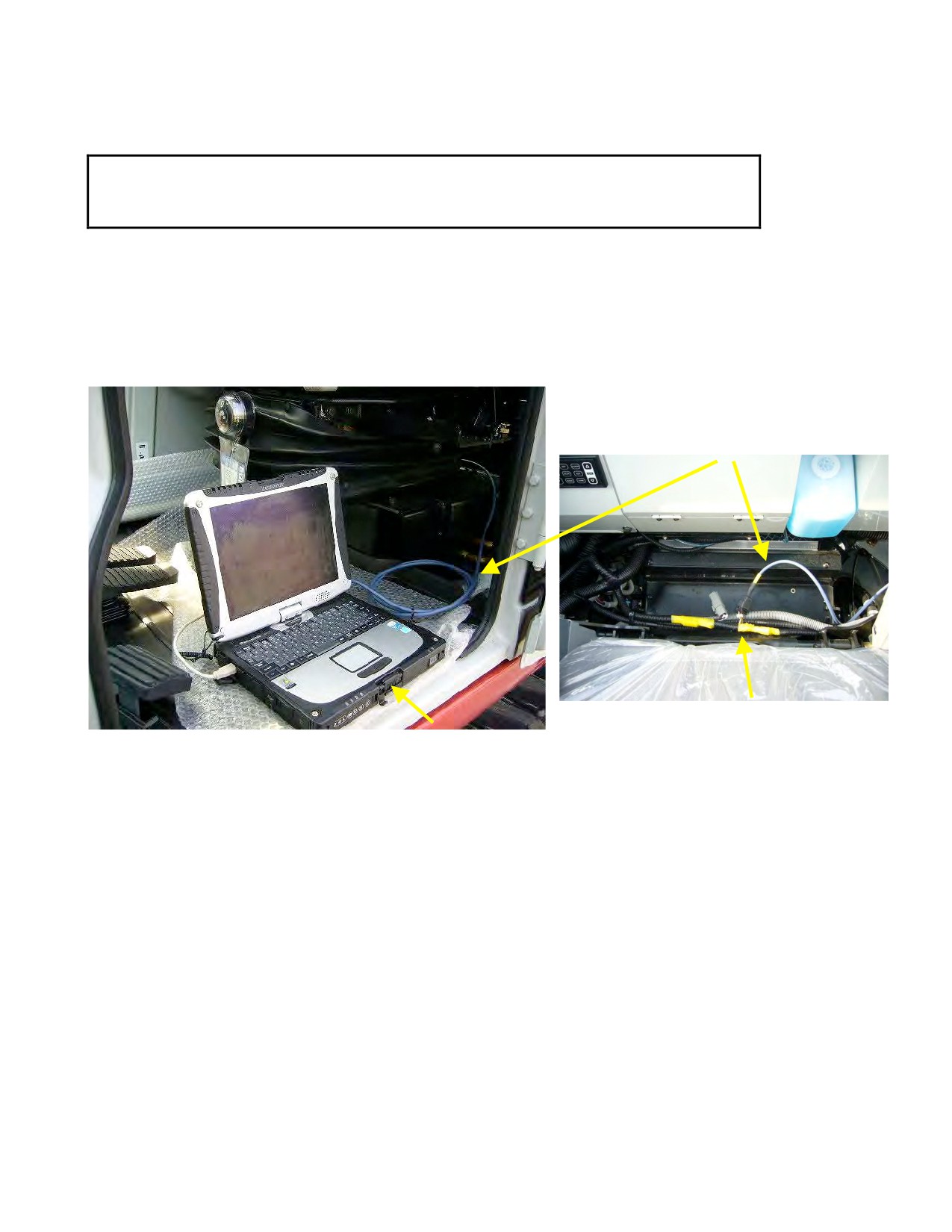
1. Connecting
-TB175W CABIN.
-Connect Maintenance cable as shown as picture.
TAKEUCHI Original USB Cable
Maintenance Connecter
LAPTOP
-Connect cable to USB port of PC.
Note: Please check COM port number of Serial to USB cable.
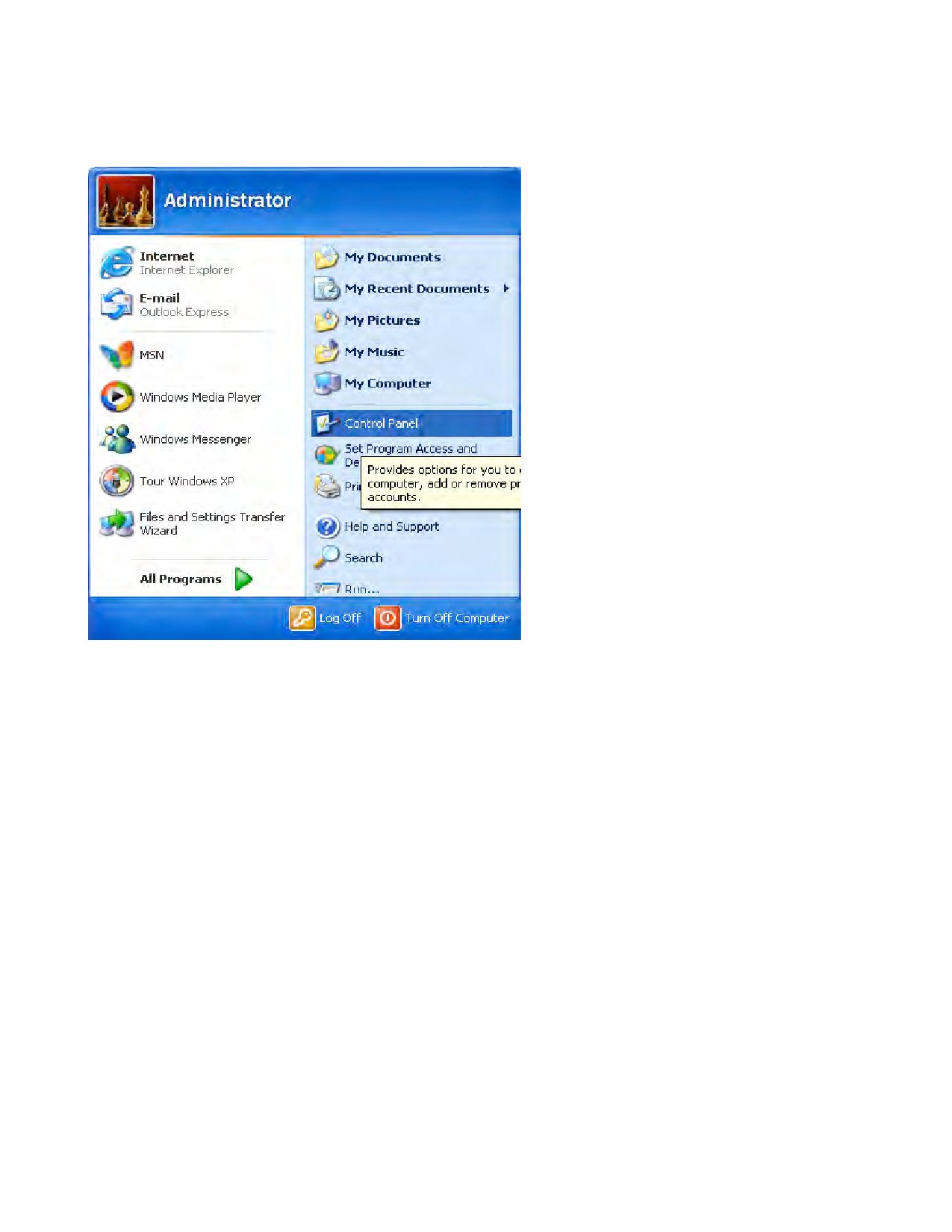
See [Control panel] in start menu.
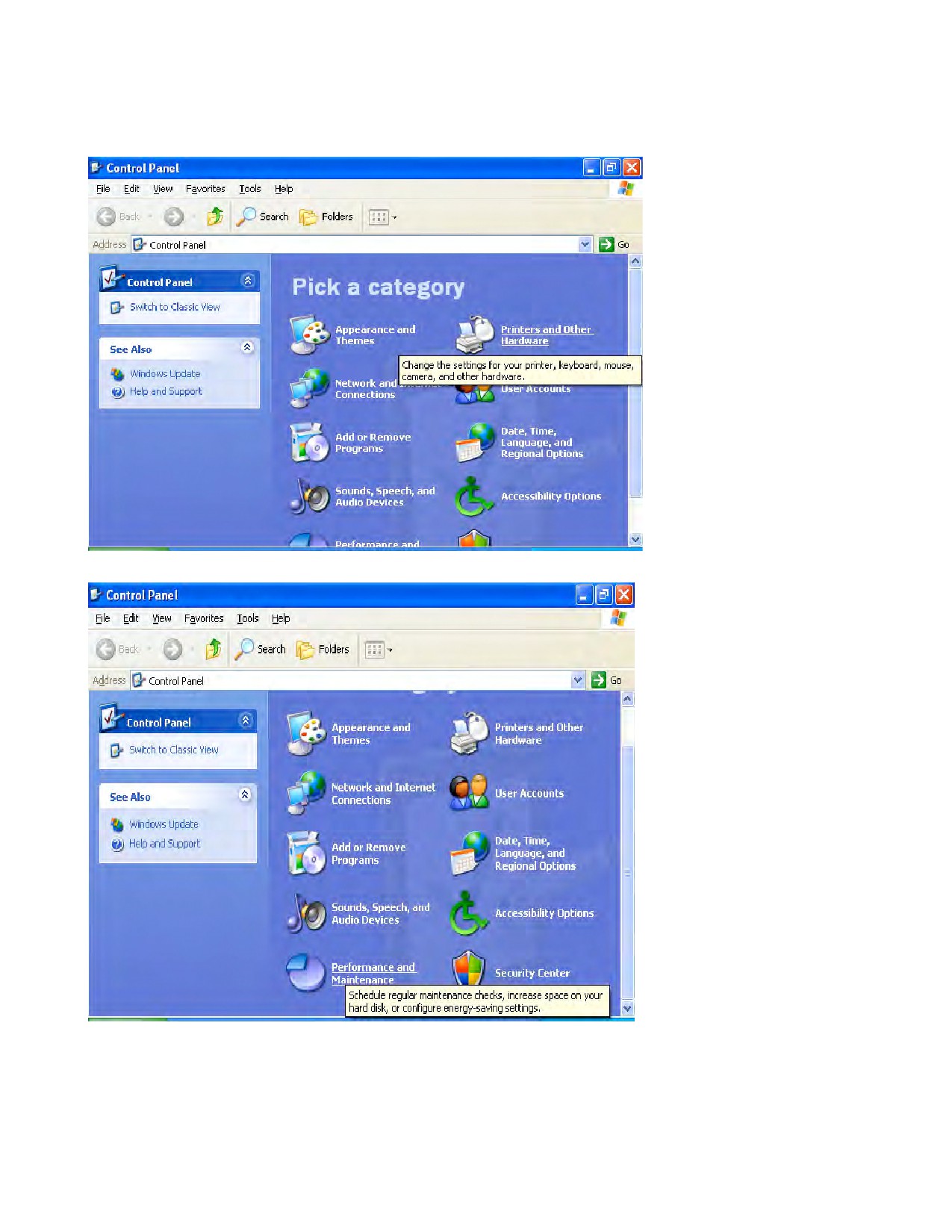
Hit [Performance and maintenance], and then hit [System].
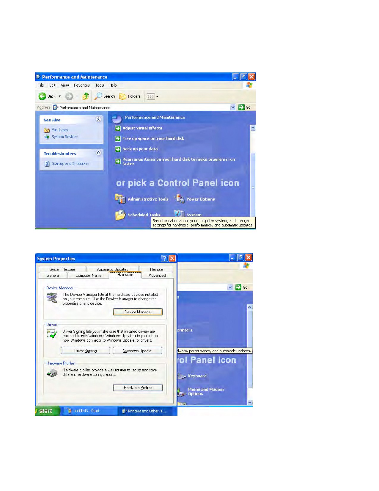
Hit [Hard ware] tag on [System property], and then hit [Device manager].
Check COM Port number on the tree.
ʤ̘̻̾̽̓́̾ ̴̥̰̻̽ ʥ̤̥̣̚
1
2
ʤ̴̵̴̥̼̰̲́̾́̽̽ ̰̳̽ ̸̴̴̢̰̰̲̽̓̽̽ʥ ̤̥̣̚
3
ʤ̴̨͈̼͂̓ʥ ̤̥̣̚
ʤ̴̸̴̙̲ͅ ̴̶̴̢̰̽́ʥ ̤̥̣̚
4
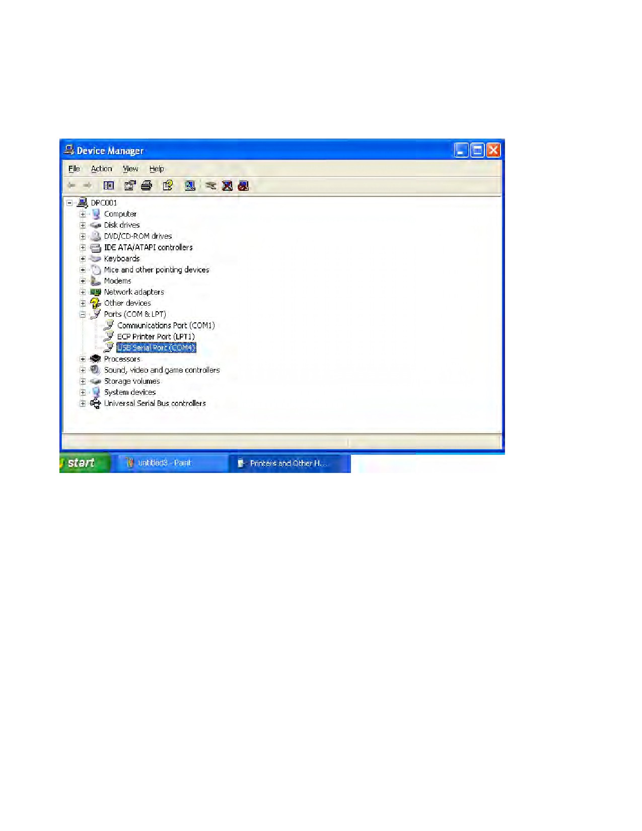
The personal computer displayed what TB175W Maintenance software could use in COM4 of the
Universal Serial Bus port.
̘hoose this COM port number at the time of initial setting.
̴̴̨ ̒ page
5
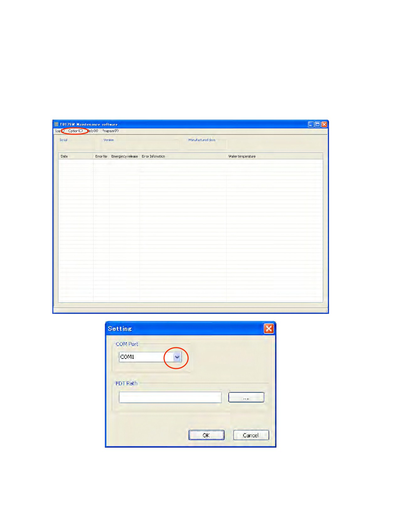
2. Maintenance software setting.
-Start [TB175W MAINTENACE SOFTWARE Ver1.0] from start menu.
-Hit [Option] ˠ [Setting]
-Choose COM port number on the list.
6
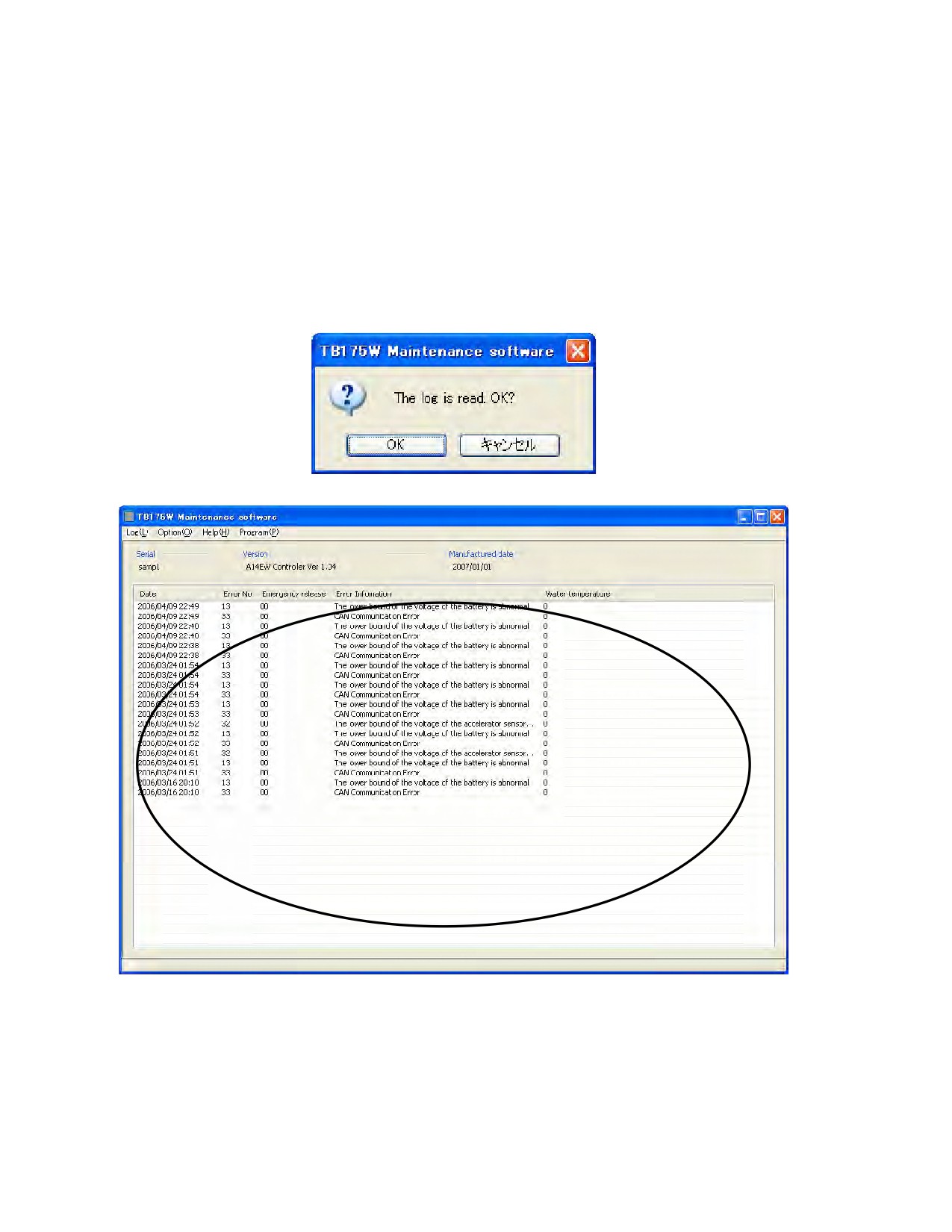
3. Monitor Error Log
-Verify connection from machine to PC.
-Turn key switch ON of machine.
-Hit [Log] ˠ [Load] on the menu.
Note: Don’t forget turn machine key switch off after loading the data.
4. Delete Log.
-When hitting [Log] ˠ [Delete], log data in the controller will be deleted.
Basically, DON’T DO IT.
7
5. Save Log
-Hit [Log] ˠ [Save]
-Chose location of file, and enter the file name.
-Log will be saved as CSV file. We can read the file by Excel.
6. Open saved Log file.
-Hit [Log] ˠ [Open]
-Choose CSV file.
7. Print Log
-Hit [Log] ˠ [Print].
-The log now you opened will be printed.
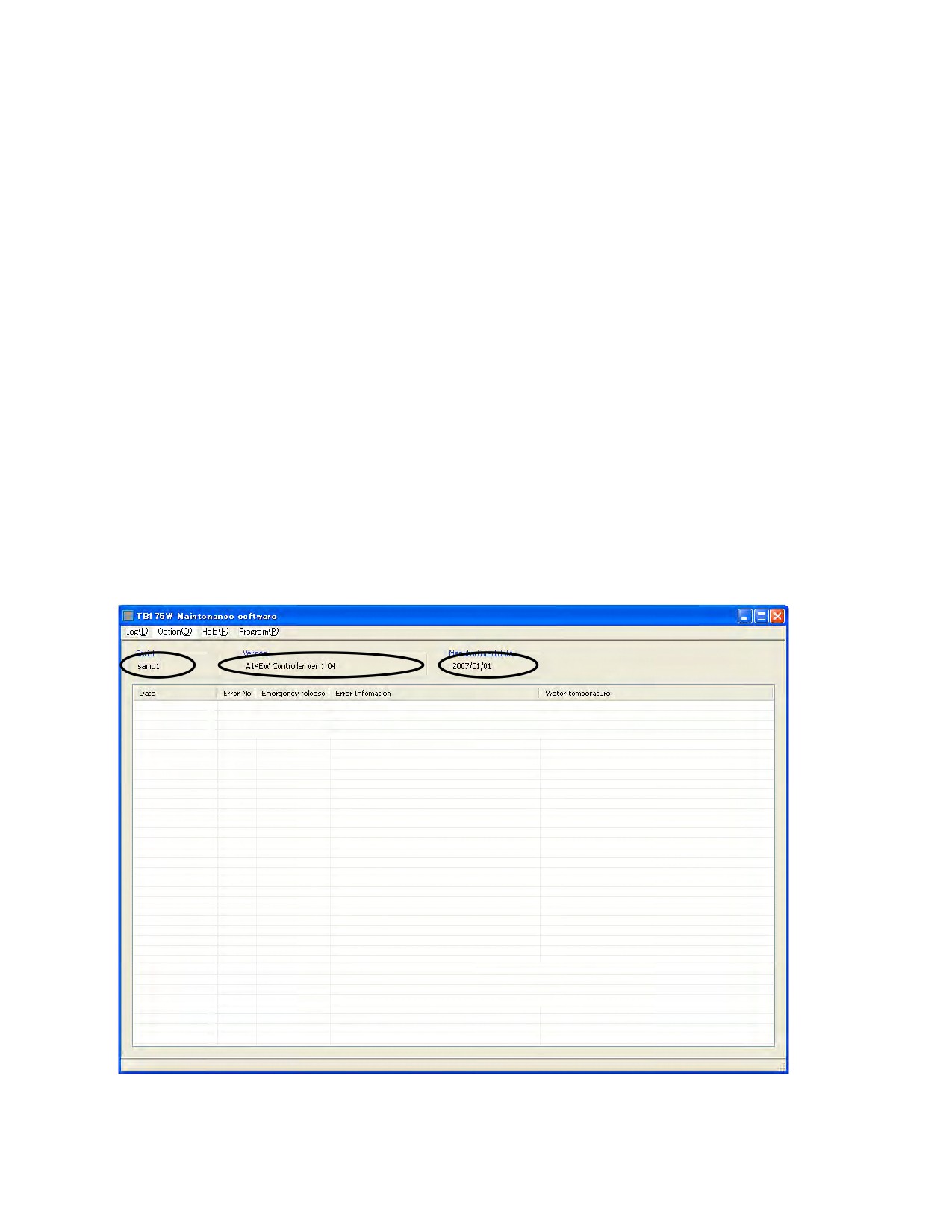
8. See Serial number of Controller.
-Hit [Option] ˠ [Version and Serial]
-Current Version of software, Serial number of controller and manufactured date of controller
will be shown.
8
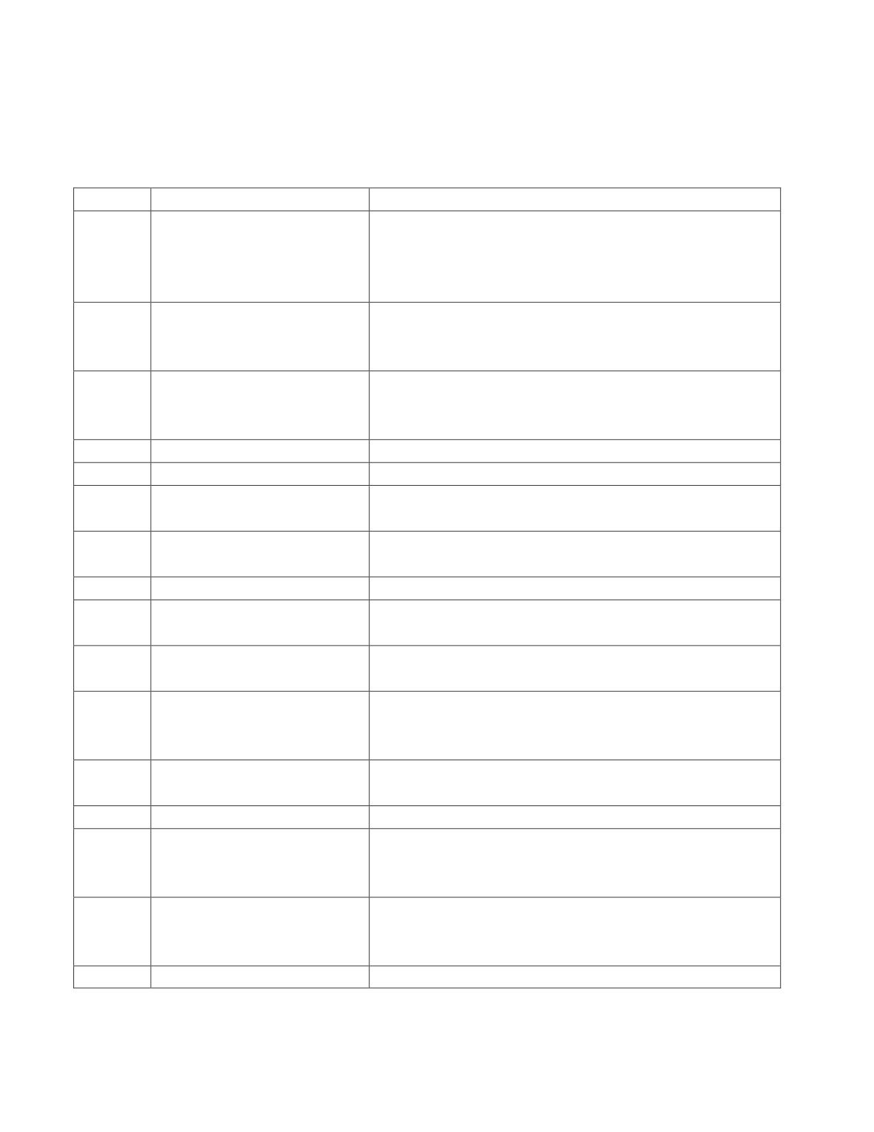
5#
8 .BJOUFOBODF TPGUXBSF 7FS
&SSPS $PEF 5BCMF
&SSPS $PEF
%JTDSJQUJPO
/PUF
,FZ TXJUDI TUBSUFS TJHOBM XBT FOUFSFE JO MFTT UIBO
TFDPOET
,FZ 48 TUBSUFS TJHOBM BOE TUBSU
JOUFSWBM
PQFSBUJPO GPS B TIPSU UJNF
16-- BDUJPO PG &OHJOF 4UPQ TPMFOPJE XBT SFQFBUFE JO TIPSU
JOUFSWBM
&OHJOF PJM QSFTTVSF EFDSFBTF
BGUFS
FOHJOF TUBSUT
"GUFS UIF FOHJOF TUBSUT
"MUFSOBUPS
DIBSHF JT EFGFDUJWF
0WFSIFBUJOH
4JHOBM GSPN XBUFS UFNQFSBUVSF TXJUDI
"JS DMFBOFS TUPQQFE VQ
-JGUJOH PWFSMPBE BQQFBSFE NPSF UIBO TFDPOE BGUFS "$$ QPXFS
-JGU PWFS MPBE
TVQQMZ
(MPX LFZ 48 UVSOJOH PO GPS B MPOH
(MPX LFZ TXJUDI IBE DPOOFDUFE NPSF UIBO
TFDPOET
5JNF
*HOJUJPO BU UJNF PG IFBE (MPX
(MPX IBE JHOJUFE NPSF UIBO
TFDPOET
5IF VQQFS CPVOE PG WPMUBHF PG UIF
7PMUBHF BT PWFS
7 IBE CFFO NFBTVSFE PWFS
TFDPOE BGUFS "$$
CBUUFSZ JT BCOPSNBM
QPXFS XBT TVQQMJFE PS FOHJOF XBT TUBSUFE
UIF MPXFS CPVOE PG WPMUBHF PG UIF
7PMUBHF BT VOEFS
7 IBE CFFO NFBTVSFE PWFS
TFDPOE BGUFS "$$
CBUUFSZ JT BCOPSNBM
QPXFS XBT TVQQMJFE PS FOHJOF XBT TUBSUFE
$MPDL JO UIF DPOUSPMMFS IBE CFFO SFTFU
$MPDL JOJUJBMJ[BUJPO
'PS FYBNQMF
*U XJMM IBQQFO XIFO #BUUFSZ IBWF BCOPSNBM MPXFS
WPMUBHF JO
&OHJOF PJM QSFTTVSF TXJUDI DPOEJUJPO XBT 0'' XIFO LFZ TXJUDI XBT
&OHJOF PJM EJTDPOOFDUJPO
UVSOFE PO
"MUFSOBUPS DIBSHF EJTDPOOFDUJPO
$IBSHF TJHOBM XBT 0/ XIFO LFZ TXJUDI XBT UVSOFE PO
5IF VQQFS CPVOE PG UIF WPMUBHF PG
UIF BDDFMFSBUPS TFOTPS JT
7PMUBHF BT PWFS
7 IBE CFFO NFBTVSFE PWFS
TFDPOE
BCOPSNBM
5IF MPXFS CPVOE PG UIF WPMUBHF PG
UIF BDDFMFSBUPS TFOTPS JT
7PMUBHF BT VOEFS
7 IBE CFFO NFBTVSFE PWFS
TFDPOE
BCOPSNBM
$"/ $PNNVOJDBUJPO &SSPS
9