SANY Excavator SY335 (Part Number: 11282013). Safety, Operation & Maintenance Manual - page 8
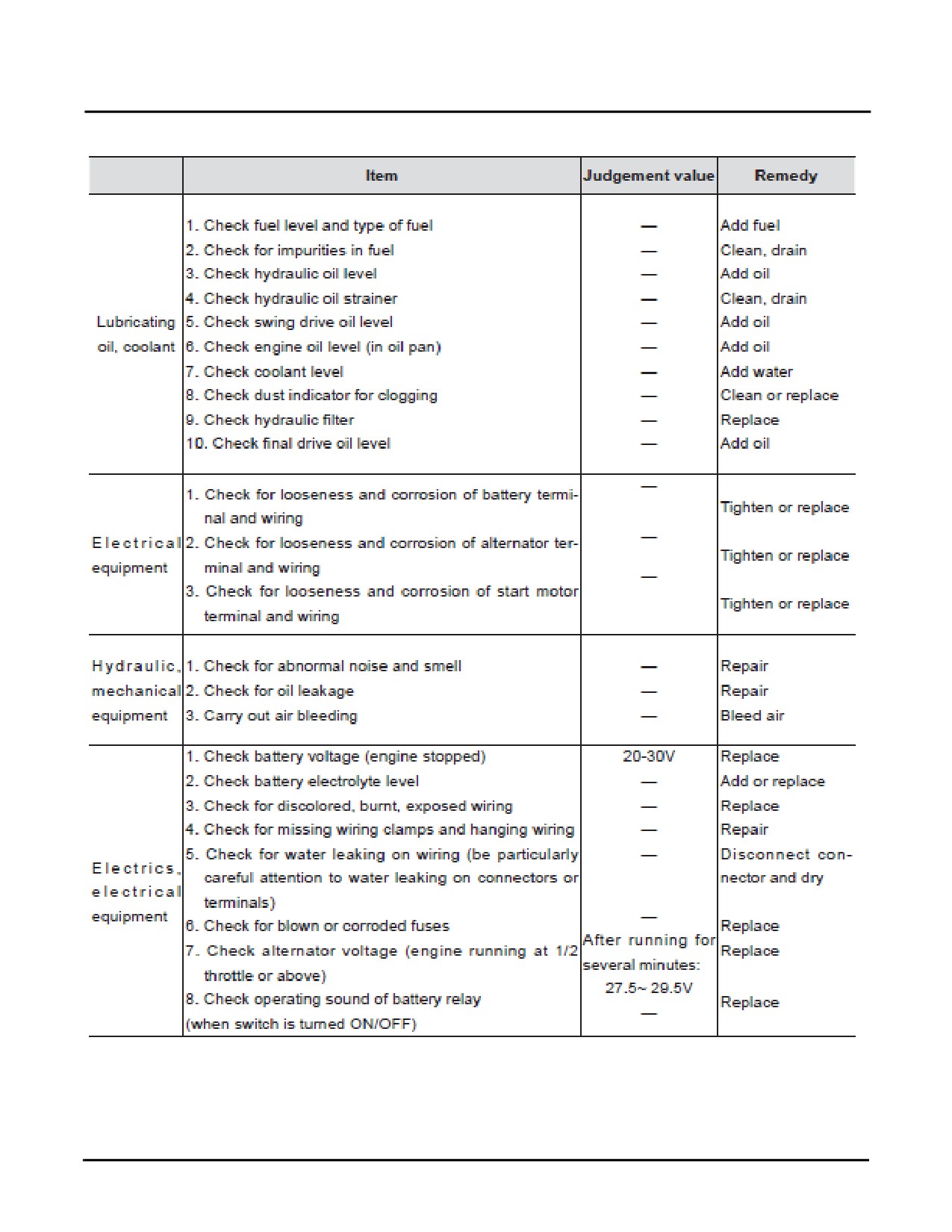
2,000 Hours of Service
SY335 Excavator
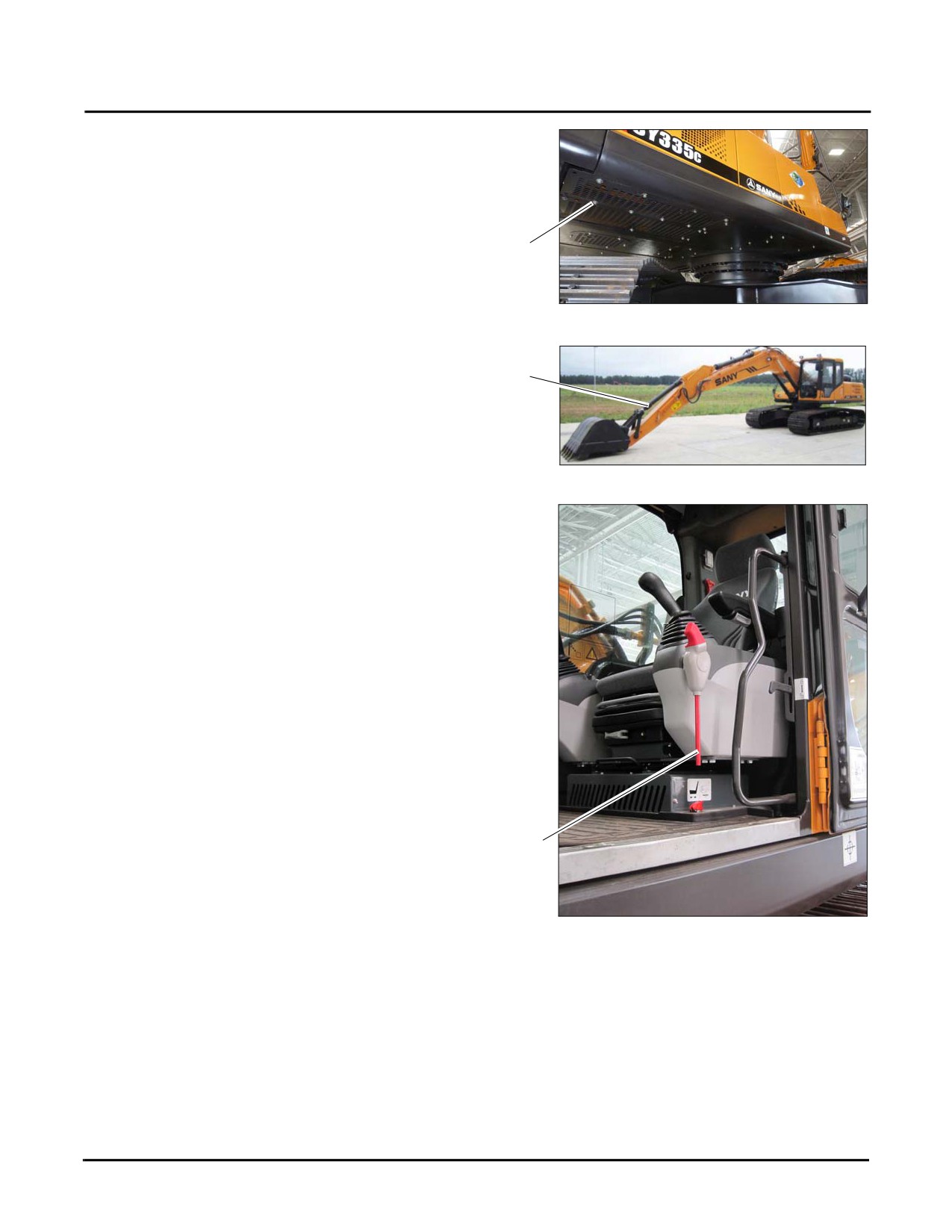
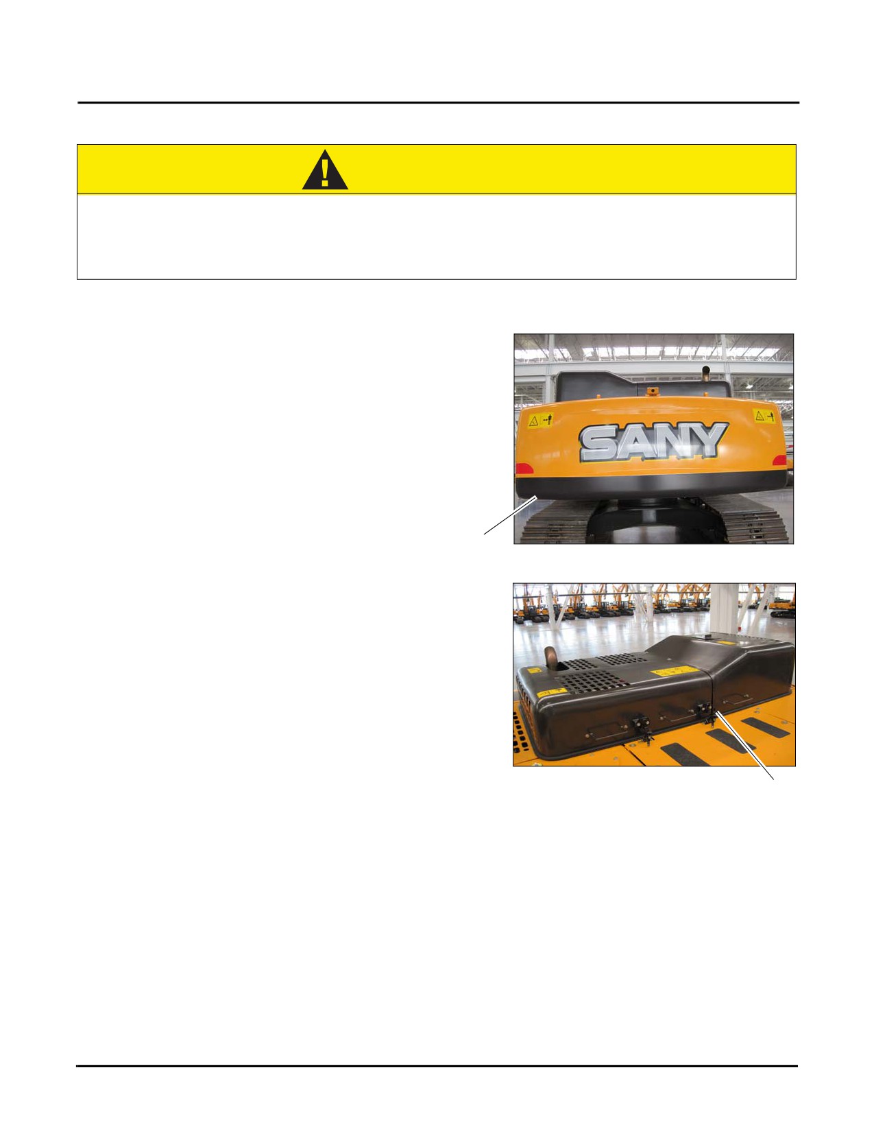
2. Unscrew the bolts of the hydraulic tank cover plate (b)
and remove the cover plate to access the bottom of the
hydraulic tank.
b
Fig. 5-151
3. Position the machine as shown (c).
c
Fig. 5-152
4. Place the hydraulic lockout control (d) in the LOCKED
position and stop the engine. Move the joysticks back
and forth to relieve system pressure.
d
Fig. 5-153
5-98
SY335 Excavator
2,000 Hours of Service
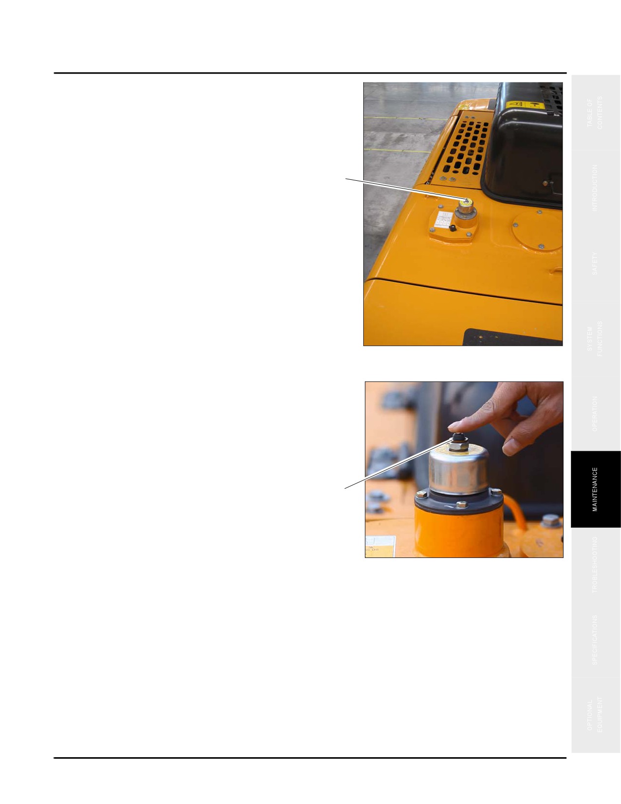
5. Release the air in the hydraulic system by pressing
down on the hydraulic breather valve (e).
e
Fig. 5-154
NOTE: See “Hydraulic System Breather Filter” on
page 5-79 for location and further information.
e
Fig. 5-155
5-99
2,000 Hours of Service
SY335 Excavator
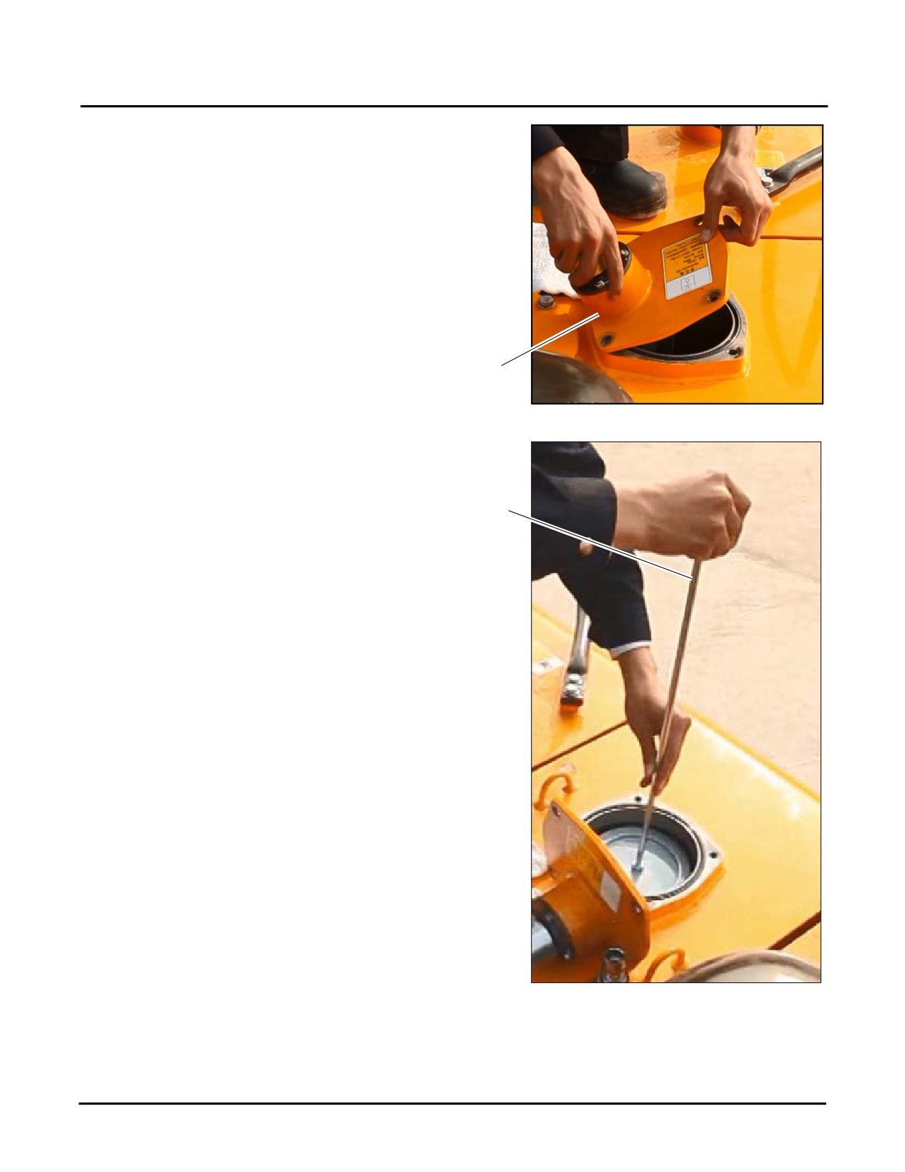
6. Remove all four bolts holding the filler cover (f) in
place. Place the cover off to the side in a clean place.
f
Fig. 5-156
7. Under the filler cover is a handle connected to a rod.
Hold the top end of the rod (g) and pull it upward in
order to remove a spring and filter.
g
Fig. 5-157
5-100
SY335 Excavator
2,000 Hours of Service
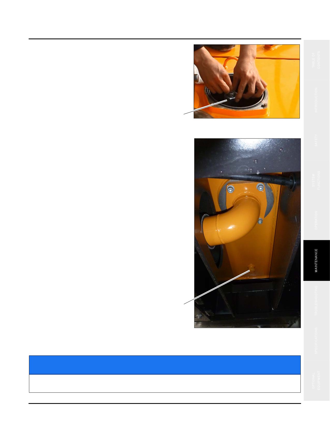
8. .Clean the filter (h) of all dirt by flushing it with mineral
spirits. Replace if damaged.
NOTE: See “Fluids & Lubricants” on page 5-11 for the
correct type of mineral spirits.
h
Fig. 5-158
9.
Place a suitably sized pan under the drain plug (k).
Remove the drain plug to drain the oil. Check the O-
ring on the drain plug and replace if broken.
10. Replace and tighten the plug (k) after draining.
NOTE: Tightening torque:
683.5
±
76.0lb ft
(927±103N·m)
11.
Add hydraulic oil through the filer cover (f).
12. Check and confirm that there is enough fluid in the tank
through the sight glass on the side of the hydraulic tank
(see page 5-25).
13. Replace the filter cover, spring and filter when
complete (f).
14. Start the engine, unlock the hydraulic lockout lever (d)
and run the engine for 10 minutes. Shut the engine
down and check for leaks.
15. Tighten connections if leaks found; if no leaks replace
the hydraulic tank cover plate (a) and dispose of the
k
used hydraulic oil.
Fig. 5-159
NOTICE
Dispose of contaminated oil properly. Failure to do so will violate environmental laws and
ordinances.
5-101
2,000 Hours of Service
SY335 Excavator
Engine Coolant
CAUTION
Do not remove the filler cap while the engine is hot. Engine coolant is under pressure when
hot and will spurt out. Always wait for the engine to cool to outdoor ambient temperatures
before removing the filler cap. Failure to follow this warning could result in minor or major
injury.
NOTE: See “Fluids & Lubricants” on page 5-11.
1. Swing the upper structure in order to position the drain
valve beneath the radiator for better access.
2. Unscrew the bolts of the radiator tank cover plate (a)
and remove the cover plate to access the bottom of the
hydraulic tank.
a
Fig. 5-160
3. Shut down the engine. Go the engine compartment and
open both doors (b).
Fig. 5-161
b
5-102
SY335 Excavator
2,000 Hours of Service
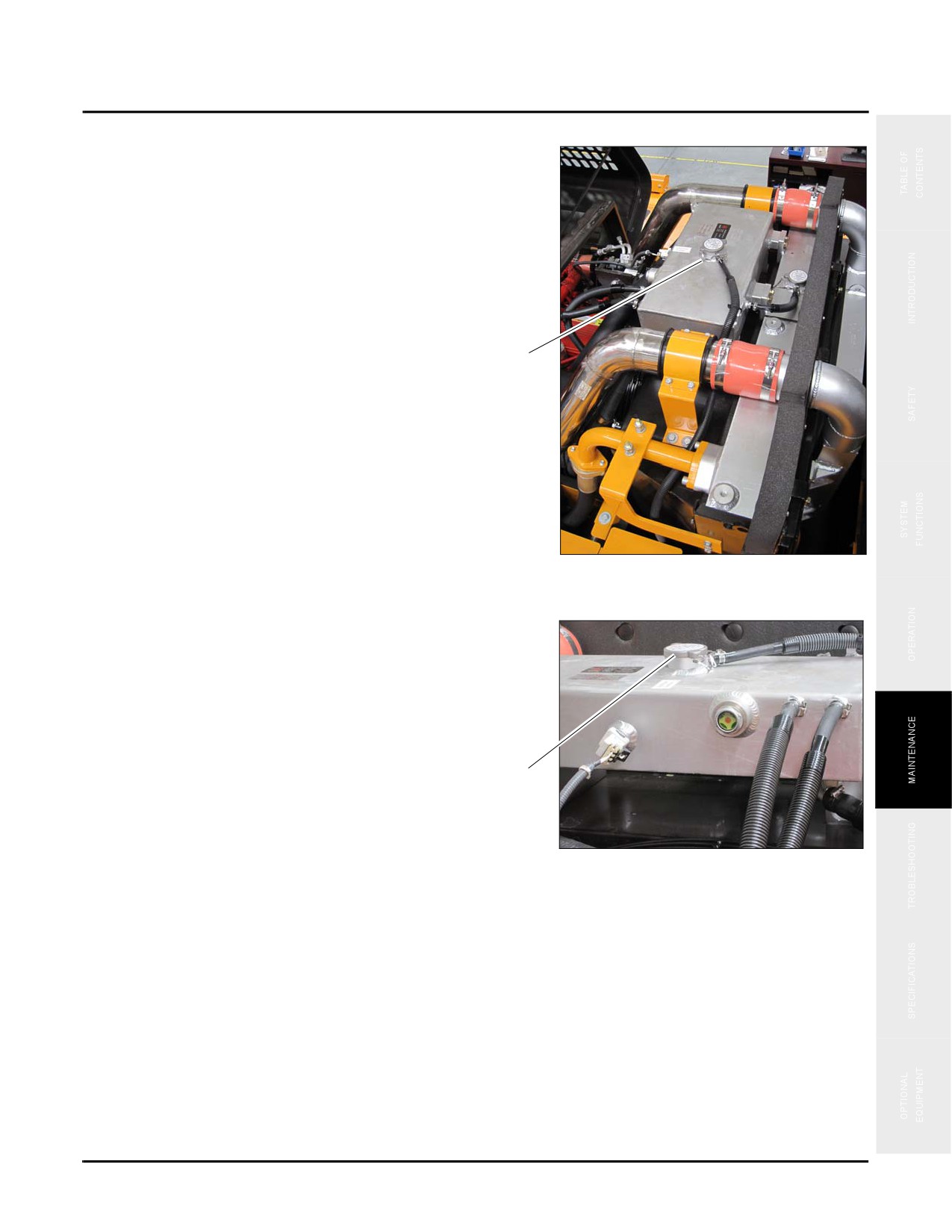
4. Go to the expansion tank filler cap located above the radiator at (c).
c
Fig. 5-162
5. Slowly open the expansion tank filler cap (d) to release
the cooling system pressure. Remove the cap when all
pressure has been relieved.
d
Fig. 5-163
5-103
2,000 Hours of Service
SY335 Excavator
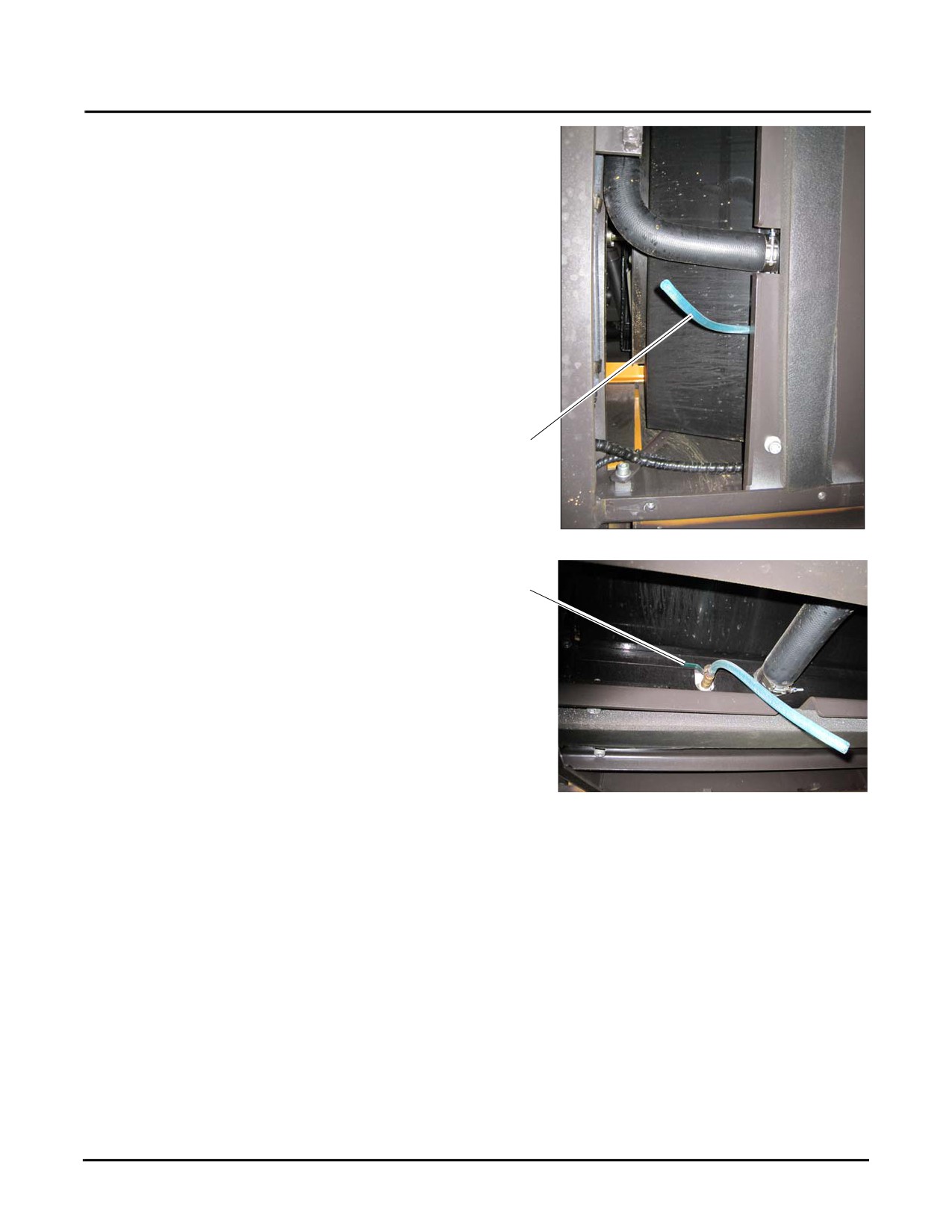
6. Place a suitable catch container (12.5 gal/48 L) under
the radiator drain hose (e).
NOTE: See “Fluids & Lubricants” on page 5-11 for
additional information on capacity.
e
Fig. 5-164
7.
Open the radiator drain valve (f) and allow the coolant
to completely drain into the catch container.
f
8.
Reinstall and tighten the drain valve (f) after the cooling
system is empty.
9.
Add new coolant directly into the expansion tank filler
neck (d) until the coolant level reaches the bottom of the
filler neck inspection hole.
NOTE: See “Fluids & Lubricants” on page 5-11 for the
type of coolant to be used.
Fig. 5-165
10. Start the engine and run it at idle speed for about 5
minutes and allow the coolant level to drop.
11.
Shut down the engine, check the fluid level and add fresh coolant directly into the expansion tank filler neck
until the coolant level again reaches the bottom of the filler neck inspection hole. (See “Engine Coolant Level”
on page 5-21.)
12. Reinstall the expansion tank filler cap.
13. Replace the radiator tank cover plate and dispose of the used coolant.
5-104
SY335 Excavator
2,000 Hours of Service
NOTICE
Dispose of contaminated coolant properly. Failure to do so will violate environmental laws and
ordinances.
Final Drive Oil
CAUTION
When the engine is just shut off, the oil and final drive components are still hot and can
burn. Wait until the oil ad the final drive has cooled before servicing.
Residual pressure in the final drive can cause oil to squirt out or the screw plug to fly out.
Slowly loosen the screw plug in order to release the pressure. Personal injury could result if
you stand in front of the plug as you loosen it.
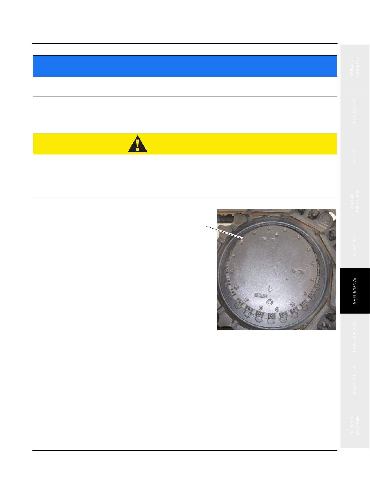
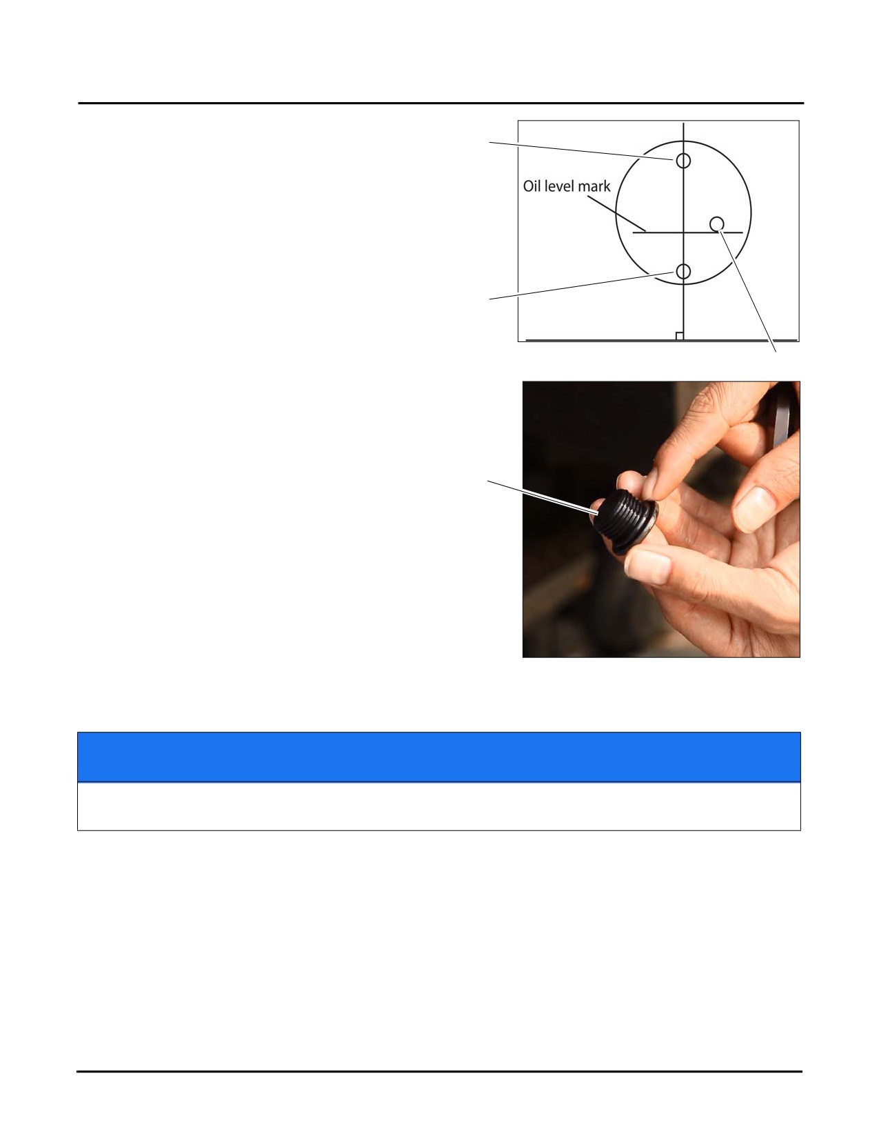
1. Drive the machine on to a flat surface placing the final
drive cover such that the plugs line up as shown (a).
a
Fig. 5-166
5-105
2,000 Hours of Service
SY335 Excavator
2.
Adjust the position of the final drive cover by driving
forward/backward so the filler cap plug (b) is at the top
b
of the cover such that if a line was drawn through the
drain screw plug (c) it would be perpendicular to the
ground.
3.
Use a flat tip screwdriver to eliminate dirt from the
hexagonal socket of plugs (b-c-d) in order to avoid
damage to the bolts.
c
4.
Place a suitable sized container (1 gal/4 L) under drain
plug (c) to catch the oil. and remove the drain plug
slowly taking care not to stand in front of the drain plug.
Fig. 5-167
d
5.
Check the O-ring on screw plug (c), replace the O-ring
if broken.
6.
Replace and tighten drain plug (c) and remove plugs (b)
and (d).
c
7.
Add new oil through the filler cap plug (b).
NOTE: See “Fluids & Lubricants” on page 5-11 for
additional information.
8.
When the oil is seen coming out of the final drive oil
check plug (d), reinstall both plugs (b) and (d), tighten
the plugs to 50 ft•lb (68 N•m).
9.
Repeat this process for the other final drive, dispose of
Fig. 5-168
all used oil.
NOTICE
Dispose of contaminated oil properly. Failure to do so will violate environmental laws and
ordinances.
Check
Hydraulic Hoses
See “Hydraulic Hoses” on page 5-85.
Accumulator Gas Pressure
See “Accumulator Nitrogen Pressure (Breaker only)” on page 5-92 and perform this procedure every 1,000 service
hours or once each year, which ever occurs first.
5-106
SY335 Excavator
Machine Storage
MACHINE STORAGE
Follow these procedures when placing the machine in storage. Store the machine in a secure area free of public
access. If your storage area is near the ocean or other salt water environment, it is important to be aware of salt
damage. Contact your Sany1 distributor for additional storage procedures if this is case.
Short-Term Storage (Less than 30 days)
•
Clean the machine, keep it dry and fully lubricated.
•
Cover the machine to protect from dust.
Long-Term Storage (Longer than 30 days)
•
Clean the machine and travel system.
•
Keep the machine in a dry well ventilated area.
•
Lubricate oil all corrosive parts.
•
Carefully lubricate the slewing bearing teeth.
•
Change out the engine and hydraulic oils.
•
Replace all the filter elements.
•
Remove the batteries in accordance with the procedures shown in “Batteries” on page 5-45.
•
Drain the cooling system and post a sign “No Coolant in Machine System” on the crane.
•
Cover the engine with film to prevent moisture and dust.
•
Inventory and properly store all required tools.
Run the engine at low speed with no load every month. During the period, pay attention to the engine cylinder
temperature
5-107
Machine Storage
SY335 Excavator
5-108
SY335 Excavator
Troubleshooting
Troubleshooting
Before Troubleshooting
6-2
Troubleshooting Precautions
6-3
Precautions Troubleshooting Electrical Circuits
6-4
Precautions Handling Hydraulic Components
6-5
Towing the Machine
6-6
Towing Light Loads
6-7
Severe Operating Conditions
6-7
Jump-Starting the Engine
6-7
General Information
6-7
Battery Access
6-8
Connecting the Jumper Cables
6-8
Starting the Engine
6-9
Disconnecting the Jumper Cables
6-9
Fuses
6-10
Engine Failures
6-11
Failure Codes
6-20
Hydraulic System
6-22
Other Common Failures
6-25
WARNING
Read and understand all safety precautions and
instructions in this manual before reading any
other manuals provided with this equipment and
before operating or servicing it. Failure to do this
can cause property damage, personal injury or
death.
6-1
Before Troubleshooting
SY335 Excavator
BEFORE TROUBLESHOOTING
6-2
SY335 Excavator
Troubleshooting Precautions
TROUBLESHOOTING PRECAUTIONS
WARNING
Observe the following before performing any troubleshooting operations. Failure do so can
cause machine damage, personal injury or death.
Park the machine on a hard, level ground. Make sure that the safety pins and blocks are
effective.
•
Co-workers must use the same signal system. Keep irrelevant people a safe distance
from the machine.
•
If the radiator cap is removed when the engine is hot, hot coolant may squirt out and
cause burns. Wait for the engine to cool down before troubleshooting.
•
Take care not to touch any hot metal parts or be caught by any rotating parts.
•
Before disconnecting any electrical wiring, always disconnect the batteries.
•
Before removing the plug or cap from any vessel that contains pressurized oil. water, or
air, release the internal pressure. When installing a measuring device, be sure to
connect it properly.
The aim of troubleshooting is to pinpoint the basic cause of the failure, to carry out repairs swiftly, and to prevent
occurrence of the failure. A short cut to effective troubleshooting is to ask the operator questions to form some idea
of possible causes of the failure that would produce the reported symptoms.
1. When performing troubleshooting, do not hurry to disassemble the components. If components are
disassembled immediately it is possible that have no connection to the failure may be disassembled. It may
become impossible to determine the root cause of the failure. It may also cause a waste of man-hours, parts, or
fluids and may loose the confidence of the user or operator. For these reasons it is necessary to carry out a
through investigation and carry out troubleshooting in accordance with the established procedure.
2. Questions to ask the user or operator:
•
Have any other problems occurred apart from the problem reported?
•
Was there anything strange about the machine before the failure occurred?
•
Did the failure occur suddenly, or were there problems th the machine condition before this?
•
Under what conditions did the failure occur?
•
Had any repairs been carried out before the failure, if so, what and when?
•
Has the same kind of failure occurred before?
6-3
Troubleshooting Precautions
SY335 Excavator
3.
Check before troubleshooting
•
Check the oil level
•
Check for any external leakage of oil from the piping or hydraulic equipment.
•
Check the travel of the control levers
•
Other maintenance items can be checked externally, so check any item that is considered necessary
4.
Confirming failure
•
Confirm the extent of the failure yourself, and judge whether to handle it as a real failure of as a problem
with the method of operation, etc.
•
When operating the machine to reenact the troubleshooting symptoms, do not carry out any investigation
or measurement that will make the problem worse.
5.
Troubleshooting
•
Use the results of the investigation and inspection in items 2, 3 and 4 to narrow down the causes of the
failure, then use the troubleshooting as follows:
• Start from the simple points
• Start from the most likely points
• Investigate other related parts or information
6.
Measure to remove root cause of failure
•
Even if the failure is repaired, if the root cause of the failure is not repaired, the same failure will occur
again. To prevent this, always investigate why the problem occurred. Then, remove the rood cause.
Precautions Troubleshooting Electrical Circuits
1. Always turn off the power before disconnecting of connecting connectors.
2. Check that all related connectors are connected before any troubleshooting.
•
Disconnect and connect the related connectors several times to check.
3. Always connect any disconnected connectors before going on to the next step.
•
If the power is turned ON with the connectors disconnected, unnecessary abnormality displays will be
generated.
4. When carrying out troubleshooting of circuits (measuring voltage, resistance, continuity, or current) move the
related wiring several times and check that there is no change in the reading on the tester.
•
If there is any change, there is probably a short in that circuit.
6-4
SY335 Excavator
Troubleshooting Precautions
Precautions Handling Hydraulic Components
With the increase in pressure and precision of hydraulic equipment, the most common cause of failure is dirt
(foreign material) in the hydraulic circuit. When adding hydraulic fluid, or when disassembling hydraulic
equipment, it is necessary to be particularly careful.
1.
Be careful of the operating environment.
•
Avoid adding hydraulic fluid, replacing filters, or repairing the machine in rain or high winds, or places
where there is lots of dust.
2.
If disassembly or maintenance work is carried out on hydraulic equipment in the field, there is danger of dust
entering the equipment. It is also difficult to confirm the performance after repairs, so it is desirable to use unit
exchange. Disassembly and maintenance of hydraulic equipment should be carried out in a specially prepared
dust-proof workshop, and the performance should be confirmed with special test equipment.
3.
Be careful not to let any dirt or dust get in when refilling hydraulic fluid. Always keep the oil filler and the area
around it clean, and also use clean pumps and oil containers. If an oil cleaning device is used, it is possible to
filter out the dirt that has collected during storage, so this is an even more effective method.
4.
When changing the fluid, as much as possible of the old hydraulic fluid must be drained out. (Drain the fluid
from the hydraulic tank, also drain the fluid from the filter and from the drain plug in the circuit.) If any old
fluid that is left, the contaminates and sludge in it will mix with the new fluid and will shorten the lift of the
hydraulic fluid.
5.
After repairing the hydraulic equipment (pump, control valve, etc.) or when running the machine, carry out
fluid cleaning to remove the sludge or contaminates in the hydraulic fluid circuit. The fluid cleaning equipment
is used to remove the ultra fine (about 3µ) particles that the filter built into the hydraulic equipment cannot
remove, so it is an extremely effective device.
6-5
Towing the Machine
SY335 Excavator
TOWING THE MACHINE
WARNING
Towing the machine improperly or using wire rope beyond specified limits could lead to
serious injury or death.
•
Make sure that the wire ropes used for towing the machine are strong enough.
•
While towing the machine, do not use wire rope with broken wires, reduced diameter, or
knots to prevent rupture of the wire ropes.
•
Always wear protective gloves when handling wire ropes.
•
Never tow the machine on a slope.
•
Never stand between the towing machine and the towed machine when performing
towing operations.
•
Operate the machine slowly and avoid imposing any sudden load on the wire rope.
NOTE: The acceptable towing force is 9,921 ft/lb (4,500 kgf).
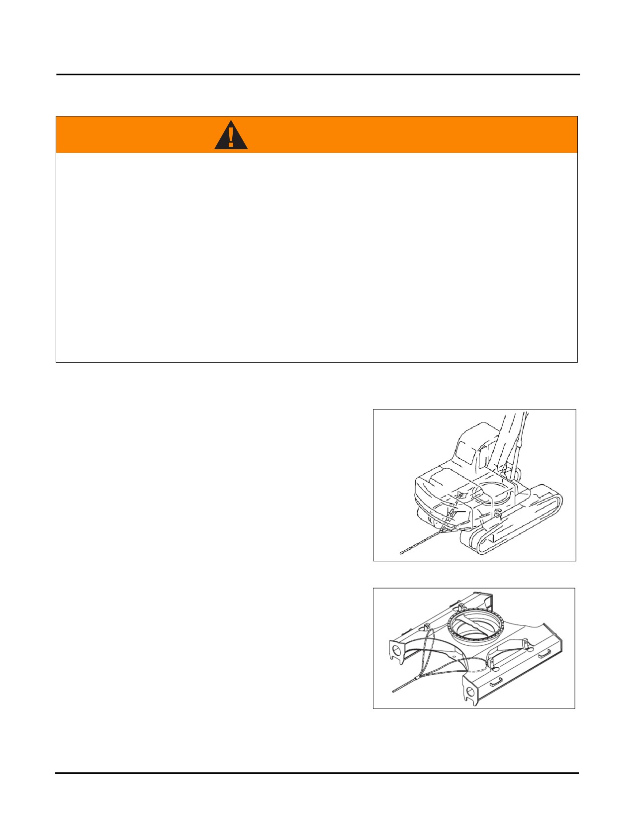
If the machine is trapped in mud and cannot move out of the
mud with its own force, or the towing force of excavator is
occupied by heavy object, wire cables can be used as shown
in the right illustration.
Place wood blocks or other protective materials between
where the wire cable contacts the machine in order to
prevent friction between the wire cable and the machine.
Fig. 6-1
Keep the wire cable parallel to the ground and align its
direction with that of the track frame.
Move at a speed of 1Km/h when towing the machine. Tow
the machine to a place suitable for repair. Never tow the
machine over a long distance.
Towing of the machine is only allowed in case of
emergency
Fig. 6-2
6-6
SY335 Excavator
Towing Light Loads
TOWING LIGHT LOADS
WARNING
Towing objects with the machine improperly could cause severe injury or death. The following
items must be observed when towing with the machine:
A shackle must be used.
Keep the wire rope parallel to the ground and align its direction with that of the track frame.
Move the machine slowly and avoid imposing sudden loads on the wire rope.
The track frame has an eye which can be use when towing light objects.
NOTE: The maximum towing force is 3,968 ft/lb (1,800 kgf).
SEVERE OPERATING CONDITIONS
When excavating in water and the track support rollers go under water add grease to the support rollers before each
operating task.
For heavy-loaded operations and deep excavation, add grease to the installation pins of the work tool (bucket,
breaker, nibbler) prior to each operation. Cycle the operation of the boom, arm, and bucket several times prior to
refilling the grease.
JUMP-STARTING THE ENGINE
General Information
•
The starting system voltage and the battery voltage in the booster machine should be no more than 24
VDC.
•
The jumper cables and their clamps must be undamaged, have no corrosion and be suitable for the battery
amperage. All clamps must be securely attached to their jumper cable ends.
•
The battery capacity of both machines must be the same.
•
Place the hydraulic lock levers of both machines in the LOCK position.
•
Set all control levers to their neutral positions.
•
Use a jumper cable to connect ONLY the positive (+) terminals of BOTH the booster machine battery and
the drained machine battery. NEVER connect the positive (+) terminal to a negative (-) terminal.
Equipment damage or a possible explosion may result. Wear protective goggles and personal protective
equipment when jump-starting an engine.
6-7
Jump-Starting the Engine
SY335 Excavator
•
Use a jumper cable to connect the negative (-) terminal on the booster machine battery to the engine block
of the troubled machine and NOT the battery. A spark may result near the battery and cause an explosion.
•
Always check and then double-check the jumper cable connections to confirm that they are correct before
proceeding with engine startup.
•
Be careful when disconnecting jumper cables after both engines are running. Never allow the jumper cable
clamps to touch each other or to touch either machine.
Battery Access
Before proceeding with any battery jump-starting procedures, follow and remember these points:
•
Battery gases are explosive. Never smoke around batteries or expose them to sparks or open flames.
•
Wear personal protective equipment when working with batteries.
•
Work in a well-ventilated area.
•
If battery acid should get on your skin or in your eyes, flush the area immediately with fresh water and seek
medical attention.
CAUTION
Failure to observe and follow these points listed above may result in equipment damage or
possible injury.
Connecting the Jumper Cables
Ensure that the key switches of both machines are in the OFF position. See “Ignition Switch” on page 3-15 for key
switch location.
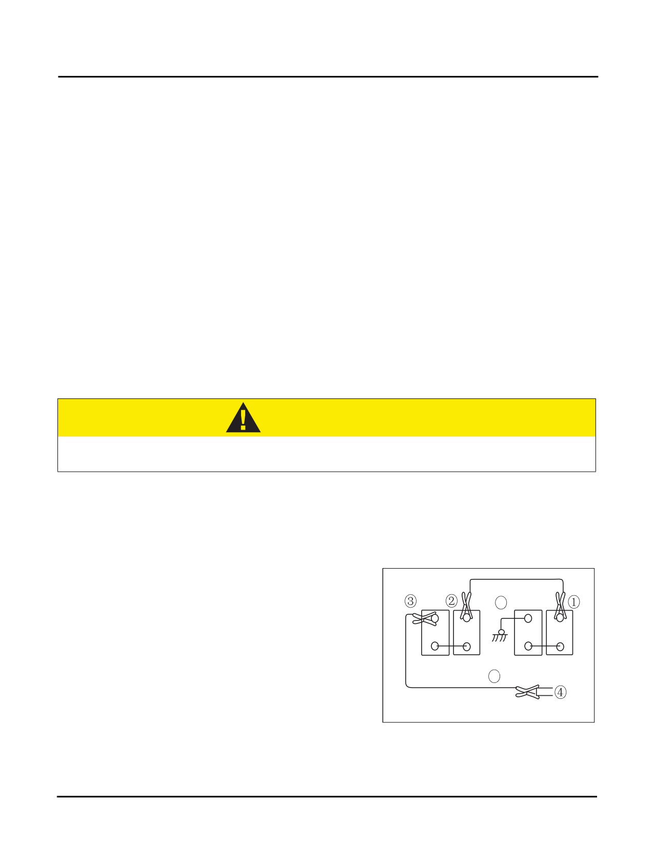
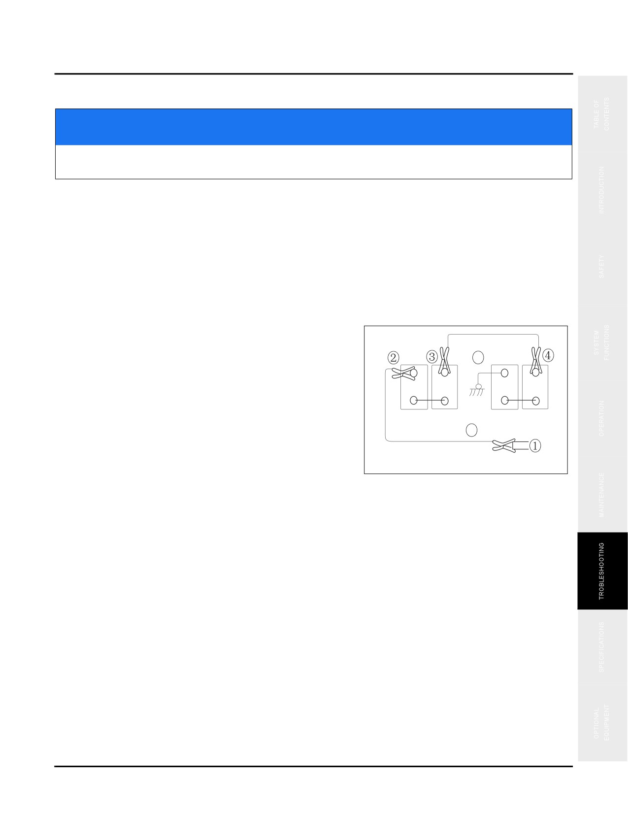
1. Clamp one end of jumper cable “A” to the positive
terminal (+) of the drained battery.
A
2. Clamp the other end of jumper cable “A” to the positive
terminal (+) of the charged battery.
+
-
+
-
3. Clamp one end of jumper cable “B” to the ground
Charged Battery
Drained battery
terminal (-) of the charged battery.
B
4. Clamp the other end of jumper cable “B” to the engine
cylinder block of the machine with the drained battery.
Fig. 6-3
6-8
SY335 Excavator
Jump-Starting the Engine
Starting the Engine
NOTICE
Ensure that all jumper cables are clamped to their connections securely. Failure to observe
and follow this notice may result in equipment damage or poor starting.
NOTE: See “Engine Start Procedure” on page 4-30
1. Start the engine of the good machine and run it at a medium speed.
2. Attempt to start the engine of the trouble machine using the key switch as normal. Retry every 3 minutes if the
engine will not start.
Disconnecting the Jumper Cables
Disconnect the jumper cables after the trouble engine has
started as described here:
A
1. Unclamp jumper cable “B” from the engine block of the
machine with the drained battery.
+
-
+
-
2. Unclamp the other end of jumper cable “B” from the
ground terminal (-) of the charged battery.
Charged battery
Drained battery
B
3. Unclamp jumper cable “A” from the positive terminal
(+) of the charged battery.
Fig. 6-4
4. Unclamp the other end of jumper cable “A” from the
positive terminal (+) of the drained battery.
6-9
Fuses
SY335 Excavator
FUSES
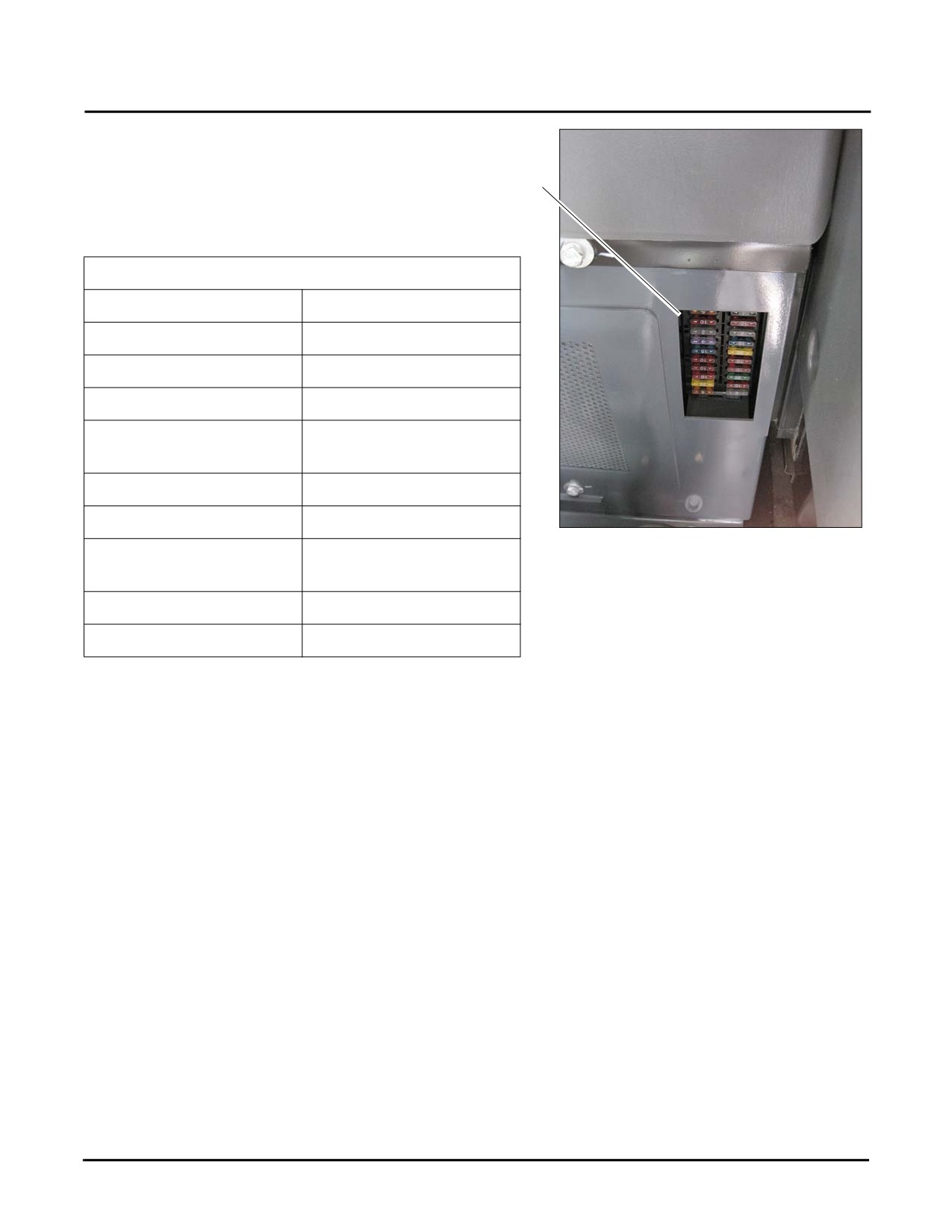
The fuse box is located in the cab behind the seat.
1
Open the fuse box door to access the fuses (1).
Fuse location, circuit & amperage
F2. Charging Lamp, 5A
F1. Starting Circuit, 30A
F4. Working Lamp, 15A
F3. KPM controller, 10A
F6. Travel Alarm, 2A
F5. Cab Lamp, 5A
F8. Radio, 10A
F7. 12V Converter, 20A
F10. Air Conditioner, 20A
F9. Diagnostic Terminal,
5A
F12. Lighter, 20A
F11. Hydraulic Nibbler, 5A
F14. Pilot Control, 10A
F13. Fueling, 15A
Fig. 6-5
F16. Display, 5A
F15. Washer & Wiper,
10A
F18. Dome Lamp, 5A
F17. KPM Controller, 5A
F20. Ignition (ECM), 5A
F19. ECM Power, 20
6-10
SY335 Excavator
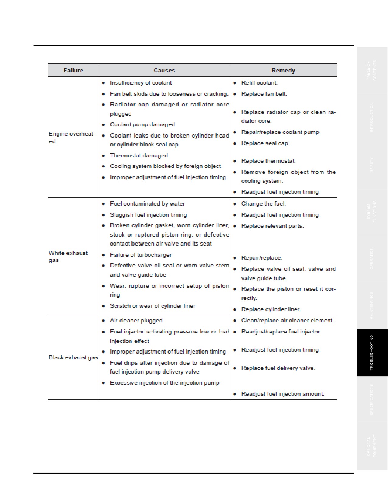
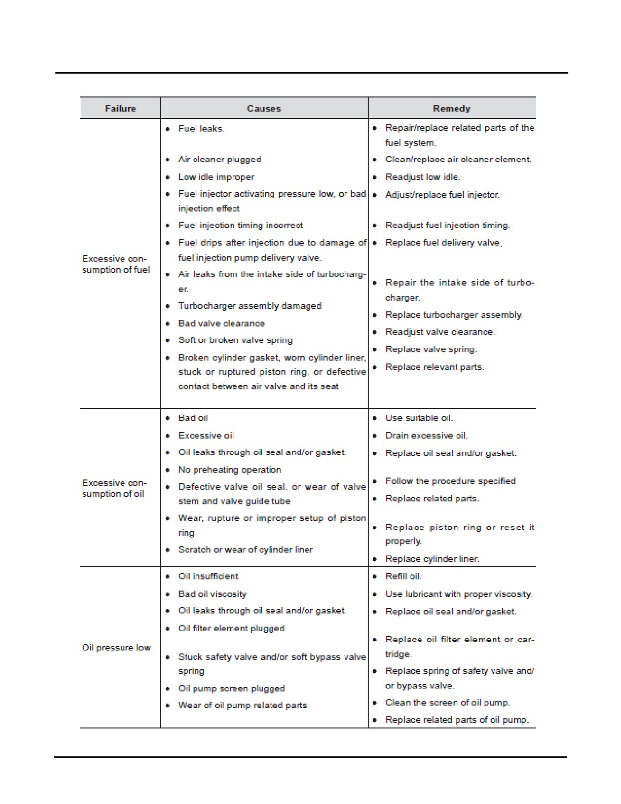
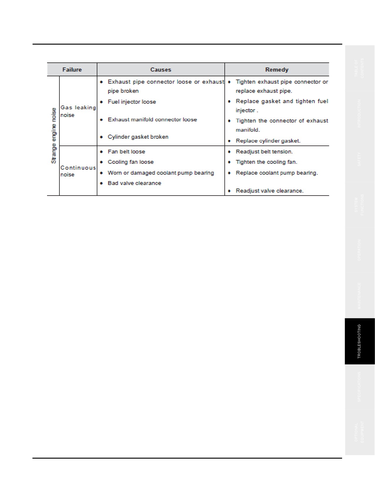
Engine Failures
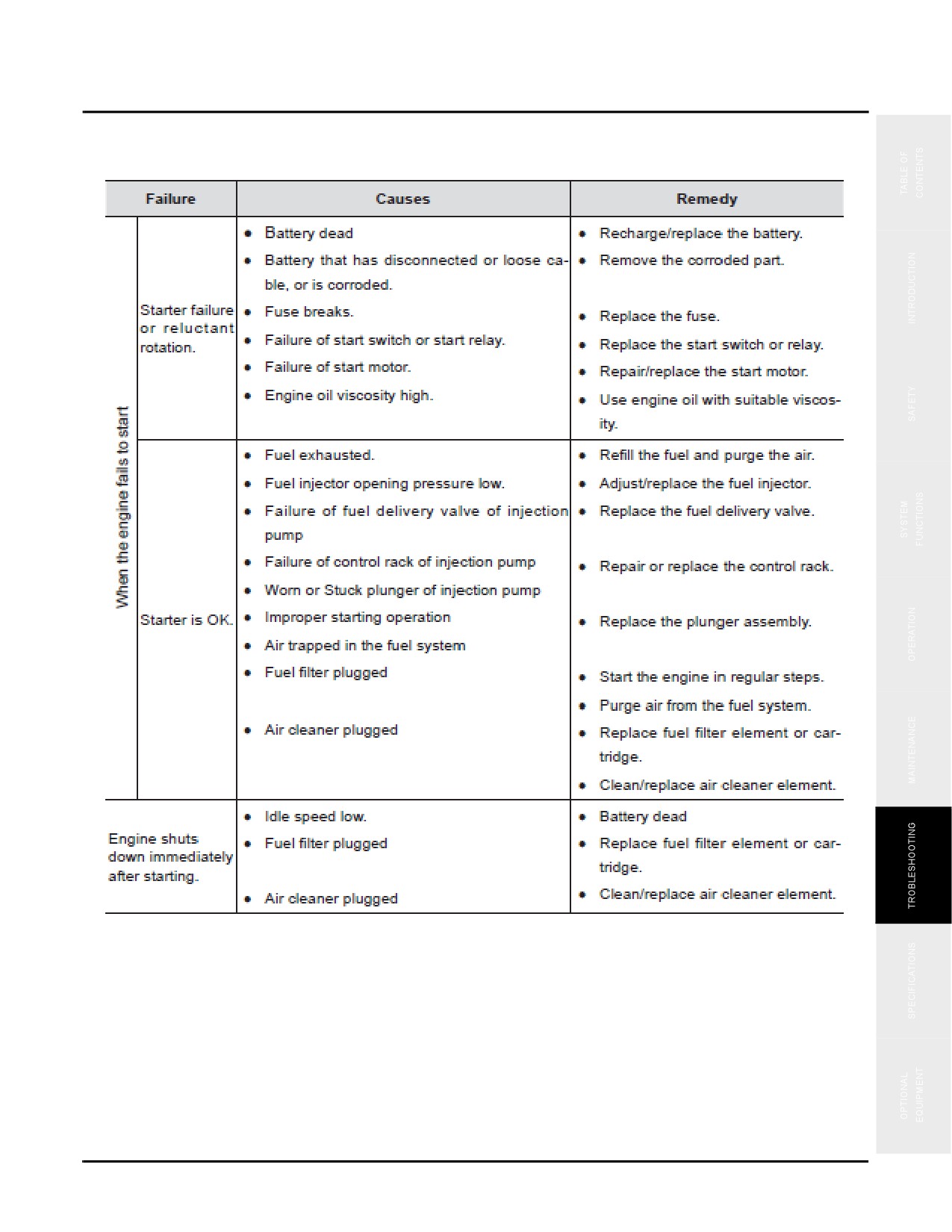
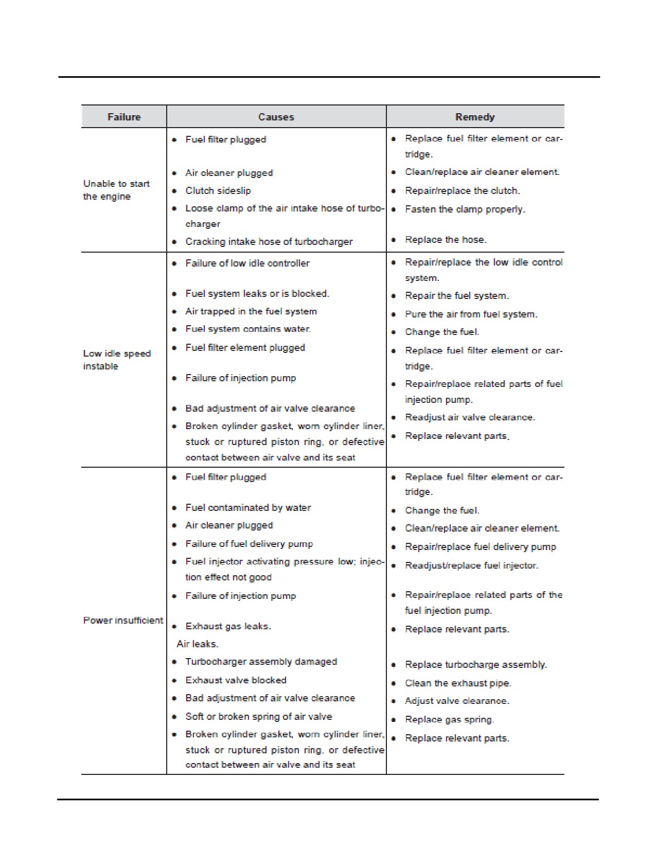
ENGINE FAILURES
6-11
Engine Failures
SY335 Excavator
6-12
SY335 Excavator
Engine Failures
\
6-13
Engine Failures
SY335 Excavator
6-14
SY335 Excavator
Engine Failures
6-15
Engine Failures
SY335 Excavator
6-16
SY335 Excavator
Engine Failures
6-17
Engine Failures
SY335 Excavator
6-18
SY335 Excavator
Engine Failures
6-19
Failure Codes
SY335 Excavator
FAILURE CODES
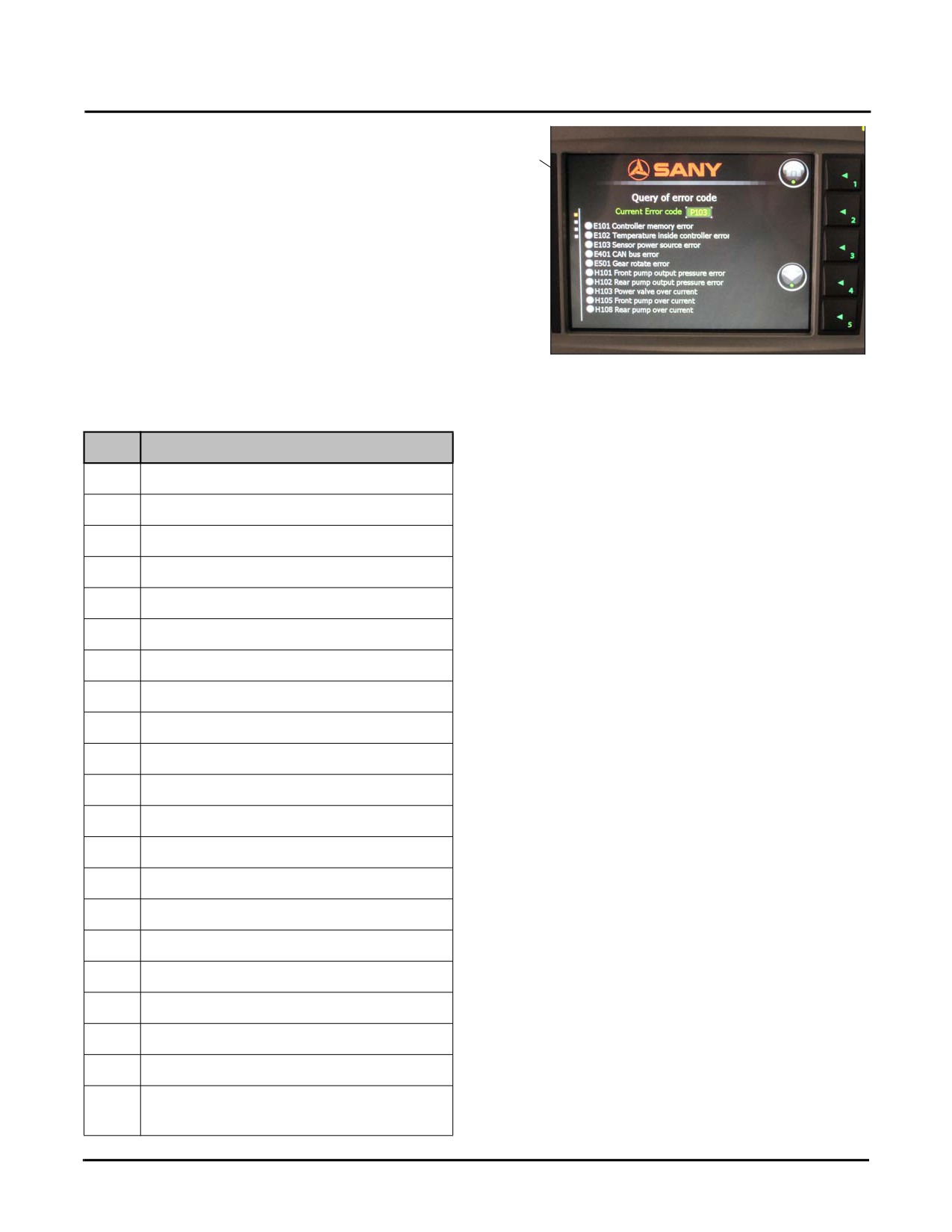
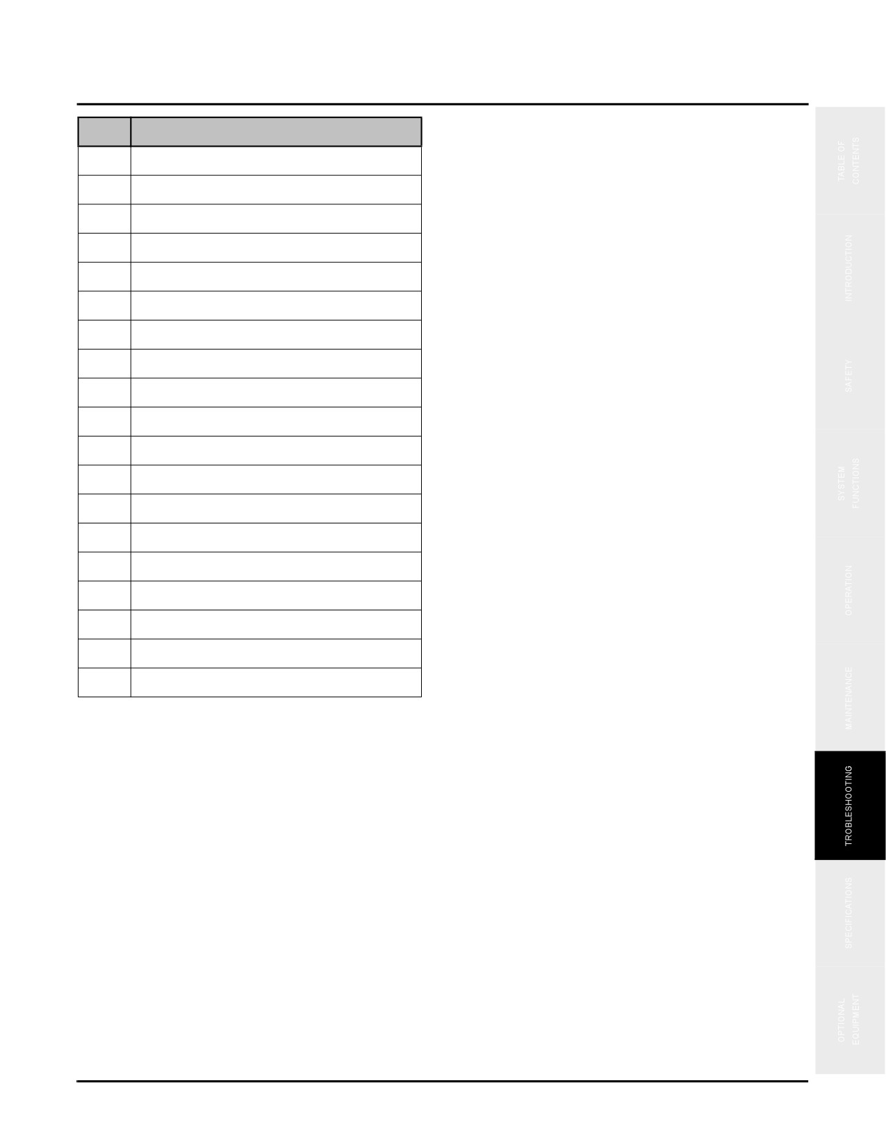
1
The failure codes (1) display in the cab on the machine
system monitor.
Fig.6-6
Code
Symptom
E101
Controller memory error
E102
Temperature inside controller error
E103
Sensor power source error
E401
CAN bus error
E501
Gear rotate error
H101
Front pump output pressure error
H102
Rear pump output pressure error
H103
Power valve over current
H105
Front pump over current
H108
Rear pump over current
H112
Backup pilot pressure abnormal
H201
Bucket-dig pilot pressure abnormal
H202
Bucket-dump pilot pressure abnormal
H203
Arm-in pilot pressure abnormal
H204
Arm-dump pilot pressure abnormal
H205
Boom-up pilot pressure abnormal
H206
Boom-down pilot pressure abnormal
H207
Left travel pilot pressure abnormal
H208
Right travel pilot pressure abnormal
H209
Swing pilot pressure abnormal
H210
Shear opening/closing pilot pressure
abnormal
6-20
SY335 Excavator
Failure Codes
Code
Symptom
H211
Shear rotating pilot pressure abnormal
H303
Swing priority current abnormal
H306
Bucket confluence current abnormal
H309
Boom priority-1 current abnormal
H312
Boom priority-2 current abnormal
H315
Travel speed shift abnormal
H401
Hyd oil temp sensor voltage abnormal
H402
Hydraulic oil temp too high
P103
Coolant level too low
P104
Engine oil pressure too low
P105
Boosting temperature too high
P302
Coolant temperature resistance abnormal
P303
Coolant temperature too high
P402
Fuel meter abnormal
P403
Fuel level low
P404
Fuel temperature too high
P501
Air filter clogged
P601
Primary fuel filter clogged
P602
Secondary fuel filter clogged
6-21
Hydraulic System
SY335 Excavator
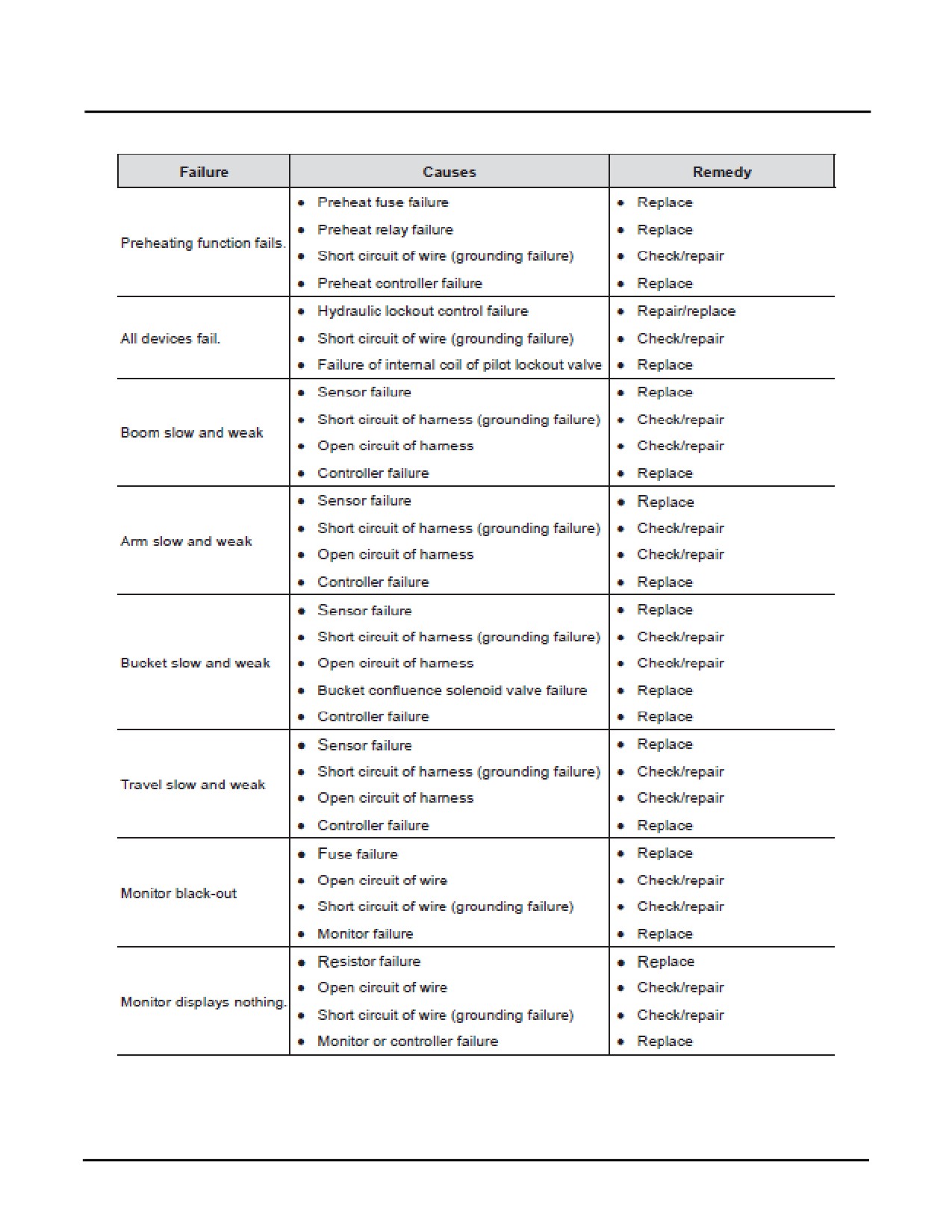
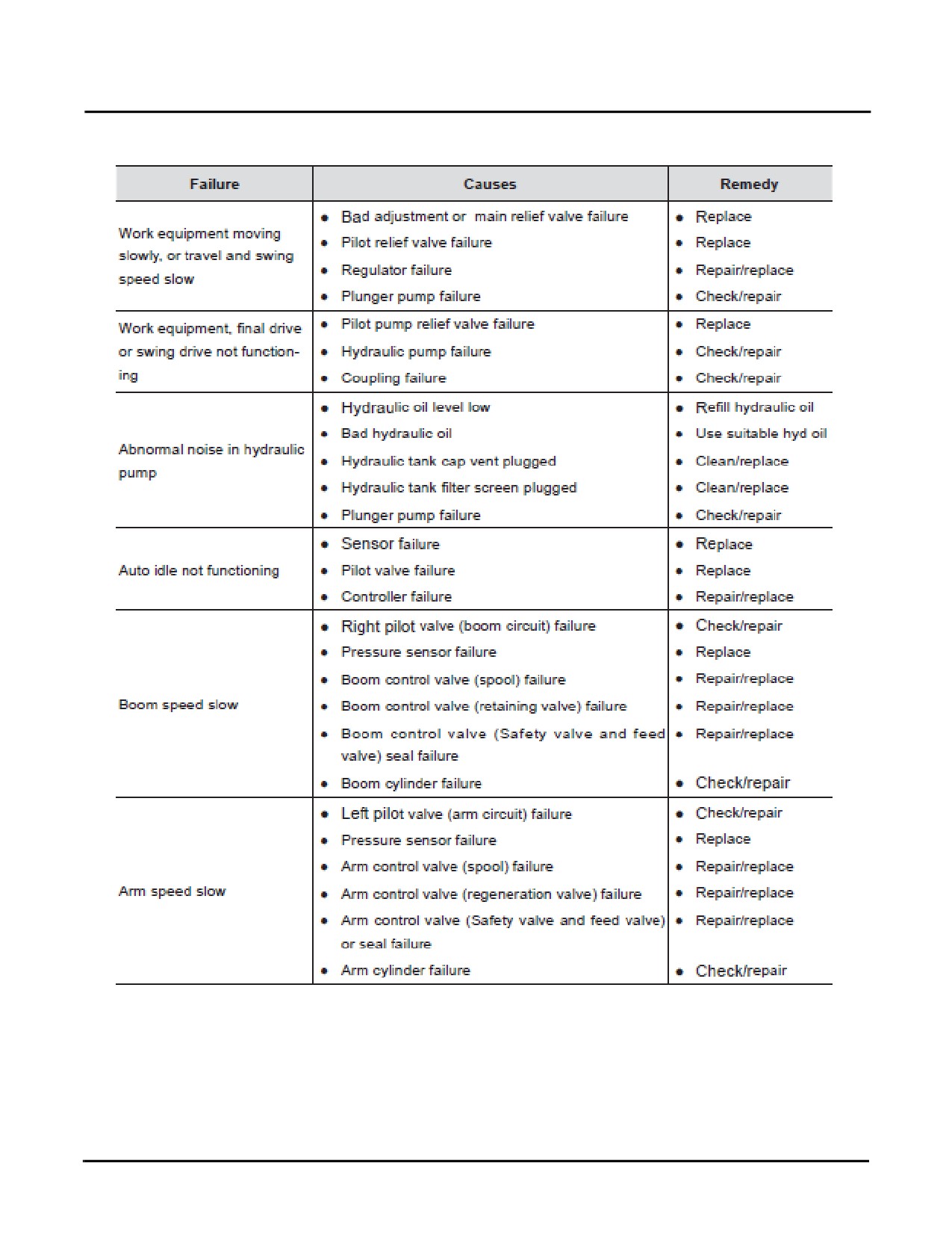
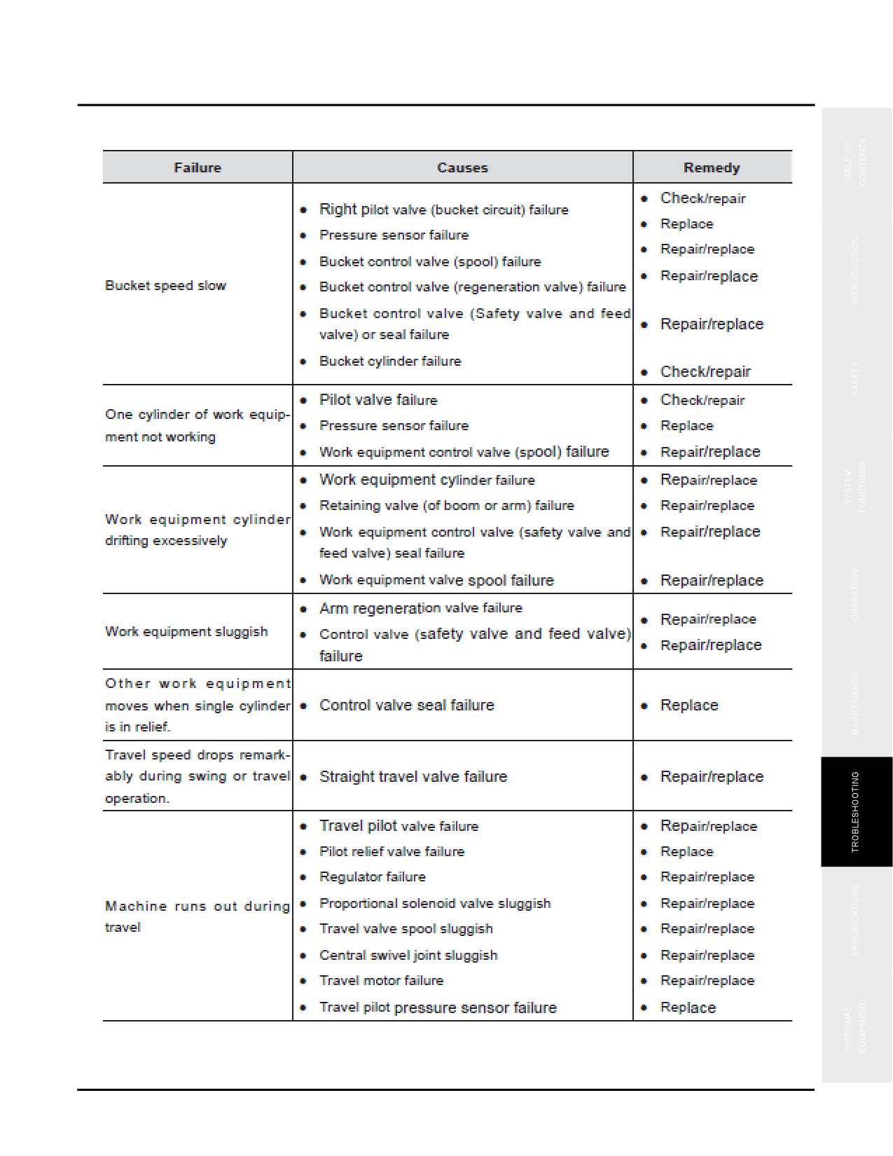
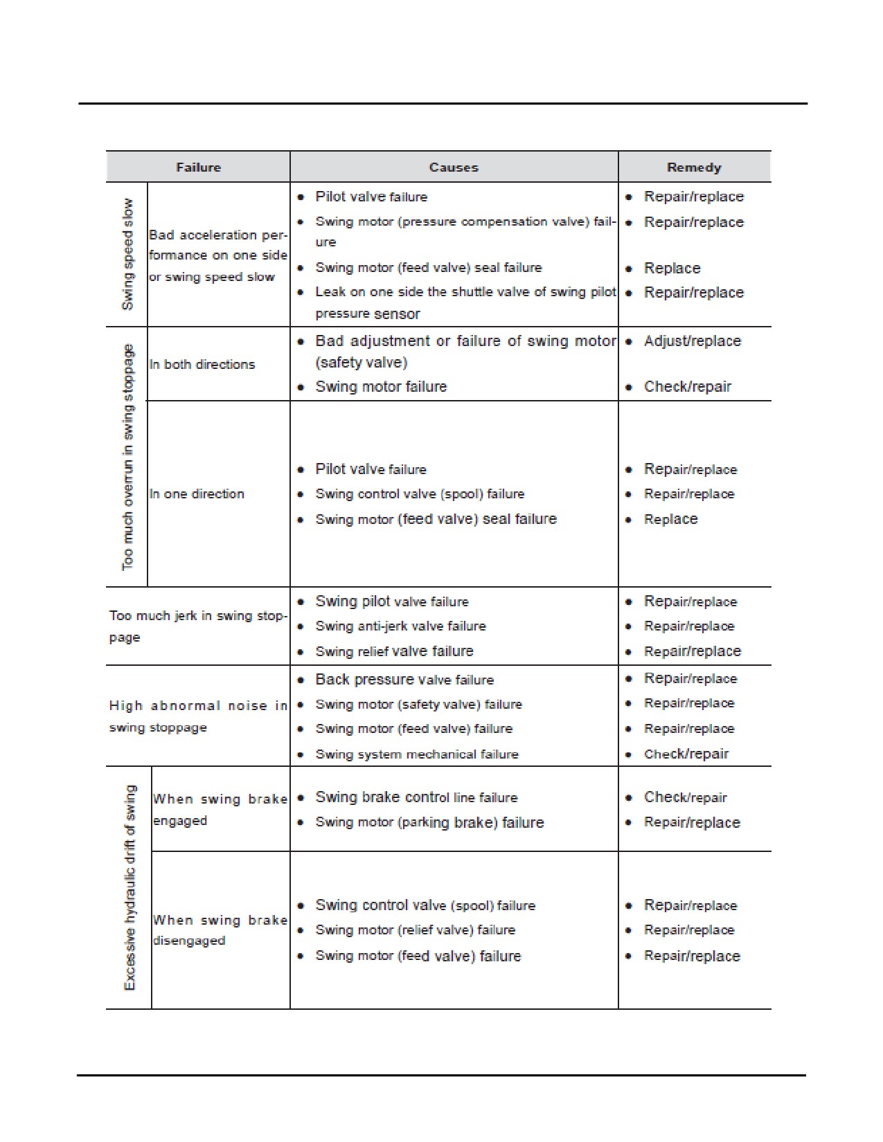
HYDRAULIC SYSTEM
6-22
SY335 Excavator
Hydraulic System
6-23
Hydraulic System
SY335 Excavator
6-24
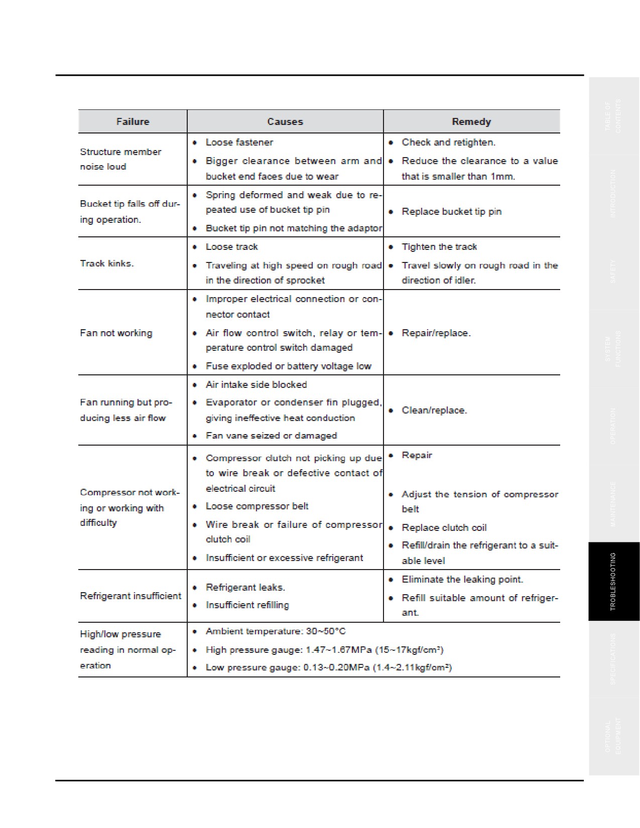
SY335 Excavator
Other Common Failures
OTHER COMMON FAILURES
6-25
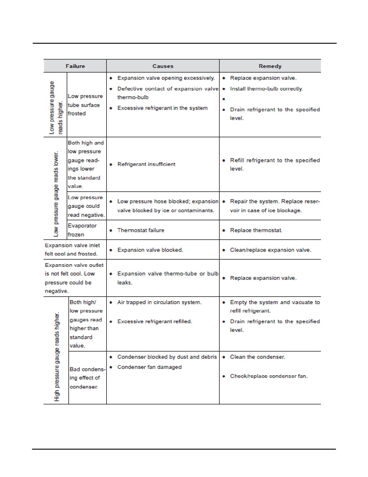
Other Common Failures
SY335 Excavator
6-26
SY335 Excavator
Specifications
Specifications
Machine Dimensions & Specifications
7-2
Operating Ranges
7-5
WARNING
Read and understand all safety precautions and
instructions in this manual before reading any
other manuals provided with this equipment and
before operating or servicing it. Failure to do this
can cause property damage, personal injury or
death.
Safety, Operation & Maintenance Manual —November 28, 2013
7-1
Machine Dimensions & Specifications
SY335 Excavator
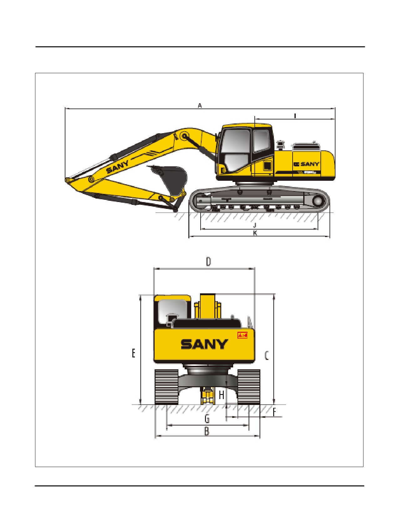
MACHINE DIMENSIONS & SPECIFICATIONS
Fig. 7-7
7-2
Safety, Operation & Maintenance Manual —November 28, 2013
SY335 Excavator
Machine Dimensions & Specifications
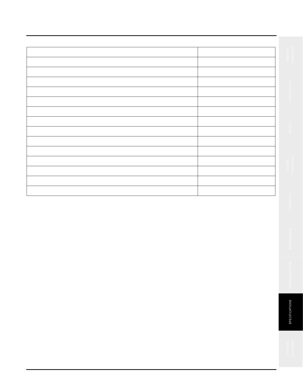
Overall Dimensions
Weight (loaded - full fuel tank, operator and standard bucket)
82,371 lb (37,363 kg)
Transport Weight - bucket (15% fuel in tank, no operator)
81,361 lb (36,905 kg)
A. Transport Length
36’ 5” (11,100 mm)
B. Transport Width
11’ 2” (3,410 mm)
C. Transport Height
11’ 6” (3,505 mm)
D. Upper Width
9’ 10” (3,000 mm)
E. Cab Height
10’ 8” (3,262 mm)
F. Std. Track shoe Width
2’ 7” (800 mm)
G. Track Gauge
8’ 6” (2,590 mm)
H. Minimum Ground Clearance
1’ 8” (541 mm)
I. Tail Swing Radius
10’ 10” (3,300 mm)
J. Length Center Idler to Center Sprocket
13’ 7” (4,150 mm)
K. Track Length
16’ 7” (5,080 mm)
Boom Length
21’ (6,400 mm)
Std Arm Length
10’ 6” (3,187 mm)
Safety, Operation & Maintenance Manual —November 28, 2013
7-3