SANY Excavator SY335 (Part Number: 11282013). Safety, Operation & Maintenance Manual - page 7

50 Hours of Maintenance
SY335 Excavator
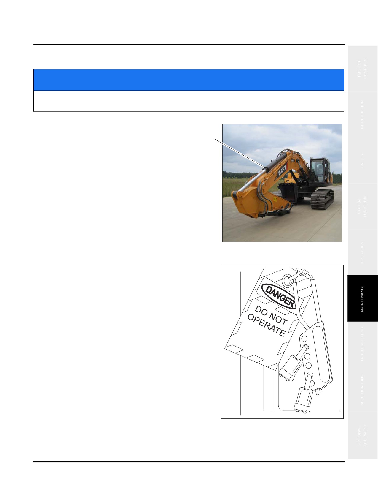
3. Inject grease into the two boom-arm joining pin fittings
(e).
e
Fig. 5-80
4. Inject grease into the arm cylinder rod end fitting (f).
f
Fig. 5-81
5-58

SY335 Excavator
50 Hours of Maintenance
5. Inject grease into the bucket cylinder root pin fitting (g).
Fig. 5-82
g
6. Inject grease into the arm-bucket joining pin fitting (h)
and the bucket-rod joining pin fitting (k).
h
Fig. 5-83
k
5-59

50 Hours of Maintenance
SY335 Excavator
7. Inject grease into the two rod joining pin fittings (m),
the bucket cylinder piston rod end fitting (n), and the
m
bucket-rod joining pin fitting (o)
n
Fig. 5-84
o
5-60
SY335 Excavator
250 Hours of Service
250 HOURS OF SERVICE
NOTICE
Failure to perform the following procedures when and how directed will result in shortened
service life of the machine or a system failure during operation.
1. Park the machine on a level flat surface (a).
a
Fig. 5-85
2. Follow the Lock-out Tag-out procedure in the Safety
section of this manual. Always allow the systems time to
cool down before proceeding with any service. See
“Lockout/Tagout Procedures” on page 2-21 for details.
NOTE: Obtain the maintenance record for this machine
and complete it at the close of all maintenance
procedures
3. With the machine secured, proceed with the following:
Change:
•
Engine Oil and Filter (see page 5-75)
•
Air Filter (see page 5-67)
•
Hydraulic Tank Return Filter Elements - Initial (see
page 5-62)
•
Replacing Hydraulic Pilot Line Filter Element
-
Fig. 5-86
Initial (see page 5-64)
•
Hydraulic Oil
- Breaker only at
400 Hours (see
page 5-65)
5-61
250 Hours of Service
SY335 Excavator
Check:
•
Air Conditioner Compressor (see page 5-65)
•
Crawler Assemblies (see page 5-70)
•
Checking and Adjusting Track Tension (see page 5-51
•
Electrical System (see page 5-28)
•
Supplemental Coolant Additive (SCA) Levels (if used) (see page 5-72)
•
Windshield Washer and Window Wipers (see page 5-72)
•
Handrails and Steps (see page 5-73)
•
Access Panels and Locks (see page 5-73)
Change:
Engine Oil and Filter
See “Engine Oil and Filter - Initial” on page 5-38
Hydraulic Tank Return Filter Elements — Initial
CAUTION
Hydraulic oil is hot and under pressure. Always wait for the machine to cool down before
proceeding. Failure to do so could result in minor or major injuries.
NOTE: Perform this procedure every 1000 service hours after this first-time replacement, or at least once each
year, whichever occurs first.
NOTE: For machines equipped with a hydraulic breaker, the hydraulic oil deteriorates faster than that of
machines operating with a bucket.
5-62

SY335 Excavator
250 Hours of Service
1. Park your machine on a hard, level ground (a). Lower
the work equipment to ground and turn off the engine.
a
Fig. 5-87
2. Turn the butterfly nut on the breather valve and press the
b
venting button (b).
3. Loosen the four bolts and remove the cap (c). When the
cap is removed, it may fly out due to the action of the
internal spring. In this case, hold down the cap when
removing the bolts.
Fig. 5-88
c
4. Remove the spring (d) and filter (e) Check the bottom of
the filter and remove dirt if any.
5. Clean the disassembled parts with mineral spirits.See
“Fluids & Lubricants” on page 5-11 for the proper grade
of mineral spirits.
6. Install a new filter element.
7. Restore the filter (e) and spring (d).
8. Install the cap (c) to its position. Hold down the cap and
Fig. 5-89
e
d
tighten the bolts.
9. In order to vent the air, start the engine and run the engine at low idle for 10 minutes.
10. Stop the engine.
5-63

250 Hours of Service
SY335 Excavator
Hydraulic Pilot Line Filter Element — Initial
NOTE: Perform this procedure every 1000 service hours after this first-time replacement or at least once each
year, whichever occurs first.
NOTE: Ensure that the machine is on flat, solid ground before proceeding.
1. Locate the Hydraulic Pilot Line Filter (a) next to the hydraulic pump.
Fig. 5-90
a
2. Use a wrench on the end of the hex end (b) at the
bottom of the filter casing to loosen the casing.
NOTE: Place an oil catch pan underneath the filter
casing to catch any oil that may leak out.
3. Loosen, then remove the filter casing
(c) with the
enclosed filter element, then remove the filter element
from the casing.
c
4. Clean the inside of the filter casing.
Fig. 5-91
b
5-64

SY335 Excavator
250 Hours of Service
5. Install a new filter inside the casing and install it in
place (d).
NOTE: Install a new gasket and O-ring
NOTE: Be careful not to cross-thread the filter casing
during installation so that the mating surface
(c) seals correctly.
Fig. 5-92
d
Hydraulic Oil - Breaker only at 400 Hours
Machines using the optional breaker attachment use up hydraulic oil at a faster rate than those using the bucket or
nibbler. Breaker equipped machines need to change hydraulic oil every 400 hours, for information on changing the
hydraulic oil see “Hydraulic Oil” on page 5-97.
Check
Air Conditioner Compressor
Inspection
1. Open both engine compartment doors (a)
a
Fig. 5-93
5-65

250 Hours of Service
SY335 Excavator
1. Go to the V-belt located at (b).
b
Fig. 5-94
2. With a force of about 58.8N (6kgf), press down with
your finger on the middle section of the belt between
the drive pulley and the compressor pulley in order to
check the deflection (b), which should be 0.2 -0.3 in (5-
8mm).
Fig. 5-95
Adjustment
1. Loosen the bolts (a) and (b).
d
2. Move the compressor (c) and its bracket (d) in order to
a
adjust belt tension.
3. Tighten the bolt
(a) and
(b) after positioning the
compressor (c).
4. Check the belt tensioner after adjustment.
c
b
NOTE: Use a tension meter to check the belt tension of
the compressor. The tension of a new belt
Fig. 5-96
should measure 470 lb/ft (637 N), an old belt
will measure 318 lb/ft (441 N)
5-66

SY335 Excavator
250 Hours of Service
5. Check for damaged pulleys and worn V-groove and V-belt. In addition, make sure that the V-belt does not rub
against the bottom of the V-groove.
Replace the fan belt if:
•
it has stretched and there is little margin left for adjustment.
•
cuts or cracks are found in the belt.
•
the belt skids or squeaks.
NOTE: Newly installed V-belts need to be readjusted after the first hour of operation.
Air Filter
See “Air Intake System” on page 5-42 to remove the air filter element.
NOTE: Some machine systems may have a clog indicator on the machine system monitor display. If this
indicator is on or activated, the air filter element should be inspected or replaced.
NOTE: The filter element must be replaced:
•
After 2 years of use.
•
After being cleaned 5 times.
•
If contaminated by rust
1. Use dry, compressed air (no more than 73 psi, 5 bar) to
clean the external surface of the filter element (a).
a
Fig. 5-97
5-67

250 Hours of Service
SY335 Excavator
2. Afterwards, use compressed air to clean the inside
surface of the filter through to the outside.
3. If compressed air is not available or otherwise cannot
be used, carefully tap the external surface of the filter
element (b) slightly to loosen and remove some of the
dust and debris.
b
Fig. 5-98
4. Shake the filter element (c) free of loose dust and
debris.
c
Fig. 5-99
5-68

SY335 Excavator
250 Hours of Service
5. Wipe the internal seal support with a clean, dry cloth.
6. Remove and inspect the secondary air filter element (d)
for any excess accumulation of dust while the primary
air filter element has been removed.
NOTE: Avoid damage to the filter element.
7. Clean and reinstall the secondary air filter element
d
Fig. 5-100
8. Install the primary air filter element, and then reinstall
the outer cover (e).
NOTE: Always read and follow any air filter
manufacturer’s instructions on the air filter
when servicing the filter element.
e
Fig. 5-101
5-69

250 Hours of Service
SY335 Excavator
Crawler Assemblies
Inspection and Lubrication
1. Use a pry bar (a) to shift and/or lift the track shoes as-
needed to perform this procedure.
Fig. 5-102
2. Check the crawler pads
(b) for damage, wear,
a
Typical
unevenness, looseness, raised sections, and tightening
of crawler pads or any other abnormality.
b
c
g
Fig. 5-103
d
e
3. Check the idler wheel (c) track rollers (d) and supporting rollers (e) for wear, lubrication and proper operation.
4. Check the crawler final drive motors (g) for wear, lubrication of the gearbox.
5. Remove as much accumulated dirt as possible from the crawler assemblies. Excess dirt requires more energy to
operate the crawlers and causes severe wear at moving parts of the crawler.
NOTE: If a track shoe is found to be defective or damaged, mark it with paint for repair reference after the
track inspection is completed.
5-70
SY335 Excavator
250 Hours of Service
Track Tension
See “Track Tension - Initial” on page 5-51 for further information.
Fuses
See “Electrical System” on page 5-28 for additional information.
5-71

250 Hours of Service
SY335 Excavator
Windshield Washer and Window Wipers
1. Check the washer fluid level inside the windshield
washer tank (a) located next to the air filter on the left
side of the machine. Add windshield washer fluid (or
water with and a small amount of suitable window
cleaner) as necessary.
a
Fig. 5-104
2. Check the operation of the windshield washer nozzle
and wiper (b) to ensure there is no smearing across the
windshield during operation. Replace the wiper blade
with a new one if smearing does occur.
3. If necessary, adjust the spray nozzle to ensure that the
fluid spray is properly directed.
NOTE: Do not operate the wiper on a dry window.
Risk of damage to the wiper blade and wiper
motor may result due to resistance of forcing a
dry wiper blade across a dry window surface.
NOTE: Use washer fluid suitable for use in very cold
or winter climates as required.
b
Fig. 5-105
5-72

SY335 Excavator
250 Hours of Service
Handrails and Steps
1. Check the mounting bolts on the handrails and steps (a)
and replace any missing or damaged mounting bolts and
tighten any loose bolts.
NOTE: Remove any tools, lubricants or debris from the
steps. Never allow loose items to remain on
the machine.
a
Access Panels and Locks
Fig. 5-106
1. Inspect all access doors and panels (a) to be sure they
a
are closed and locked properly. This is important for
the security of the machine.
2. Repair or replace any damaged locks (b). Failure to do
so could result in unauthorized tampering or vandalism.
Fig. 5-107
b
5-73

500 Hours of Service
SY335 Excavator
500 HOURS OF SERVICE
NOTICE
Failure to perform the following procedures when and how directed will result in shortened
service life of the machine or a system failure during operation.
1. Park the machine on a level flat surface (a).
a
Fig. 5-108
2. Follow the Lock-out Tag-out procedure in the Safety
section of this manual. Always allow the systems time to
cool down before proceeding with any service. See
“Lockout/Tagout Procedures” on page 2-21 for details.
NOTE: Obtain the maintenance record for this machine
and complete it at the close of all maintenance
procedures
3. With the machine secured, proceed with the following:
Change:
•
Primary Fuel Filter (see page 5-75)
•
Coolant Filter (see page 5-77)
•
Slewing Gearbox Oil (see page 5-78)
•
Hydraulic System Breather Filter (see page 5-79)
Fig. 5-109
Checks:
•
Radiator, Oil Cooler and A/C Condensor Fins (see
page 5-80)
•
Air Conditioning Fresh Air and Recirculation Air Filters (see page 5-82)
5-74

SY335 Excavator
500 Hours of Service
•
Slewing Gearbox Bolts (see page 5-84)
•
Hydraulic Hoses (see page 5-85)
•
Hydraulic pump (see page 5-85)
•
Upperworks and Lowerworks (see page 5-86)
•
Final Drive (see page 5-87)
•
Swing Gear Pinion Grease Level (see page 5-88)
Lubricate:
•
Work Equipment, (see page 5-56)
Change
Primary Fuel Filter
1. Open the right rear access panel of your machine to
locate the primary fuel filter (a).
2. Place a drain pan under the primary fuel filter to hold
the fuel drained.
a
Fig. 5-110
5-75

500 Hours of Service
SY335 Excavator
3. Loosen the drain valve
(b), to drain all water and
sediment from the filter (a).
4. Remove the fuel accumulated in the bowl.
NOTICE
Dispose of the contaminated fuel properly.
Failure to do so will violate environmental laws
and ordinances.
5. Remove the filter by turning it counterclockwise.
a
6. Clean the surface of the filter fitting and oil it prior to
replacing the old filter with a new filter.
7. Clean the filter seat and fill the new filter element with
b
clean fuel.
Fig. 5-111
NOTE: Do not remove the cover (c) when filling the
fuel. The fuel must be filled through the eight
holes
(d) around the center hole. Remove
cover (c) after refilling. Keep dirt or debris
c
from entering the fuel.
8. Apply a film of machine oil to the sealing surfaces
before installing the new filter to its fitting.
d
Fig. 5-112
5-76

SY335 Excavator
500 Hours of Service
Coolant Filter
1. Open the right rear access door of your machine to
locate the coolant filter (a).
a
Fig. 5-113
2. Close the valves on either side of the coolant filter (b).
b
3. Place a bowl under the filter to catch any coolant.
4. Turn the coolant filter (c) counterclockwise with a filter
spanner to remove the oil filter. Remove the coolant
caught in the bowl.
c
NOTICE
Dispose of the contaminated coolant properly.
Failure to do so will violate environmental laws
and ordinances.
5. Clean the coolant filter mount (d). Check the mount
seat for the presence of old filter seal. The presence of
older seal in the mount seat can cause coolant leakage.
6. Clean the coolant filter mounting surface, then coat the
new filter seal ring with a thin layer of lubricant.
Fig. 5-114
7. Thread the filter into place on its mount until the filter
d
gasket contacts the filter mount, then tighten the filter
3/4 turn more.
5-77

500 Hours of Service
SY335 Excavator
8. Open the valves on either side of the coolant filter (b &
b
c).
9. Start the engine and let it run for ten minutes. Recheck
the coolant level and fill if needed (page 5-21).
Fig. 5-115
Slewing Gearbox Oil
WARNING
The slewing gearbox oil runs hot and can burn you if opened right after the engine has
stopped. Wait for the temperature to drop and the gearbox to cool down before draining to
ensure that serious injury does not occur.
1. Open the belly plate under the hydraulic valves/slewing gearbox area (a).
Fig. 5-116
a
b
5-78

SY335 Excavator
500 Hours of Service
2. Place a suitable container (at least 2 gal/8 l) under the hose (b) to catch the oil drained from the gearbox.See
See “Fluids & Lubricants” on page 5-11 for additional information on capacity.
3. Locate the slewing gearbox and open the drain shown at
(c) near the dipstick. Let all of the oil drain from the
gearbox and then dispose of the oil.
NOTICE
Dispose of the contaminated oil properly. Failure
to do so will violate environmental laws and
ordinances.
Fig. 5-117
c
d
4. Close the drain (c) and refill the gearbox oil through the
fill point (d).
5. Fill and check the oil level using the dipstick (e), do not over fill (page 5-24). If you do overfill, drain oil until
the proper level is achieved.
NOTE: The gearbox holds 1 gal (4 L) of oil. See See “Fluids & Lubricants” on page 5-11 for additional
information on capacity.
6. Replace the belly plate below the hydraulic valves/slewing gearbox area.
Hydraulic System Breather Filter
NOTE: The maximum service interval for the hydraulic tank breather filter shall not exceed 500 hours.
Dependent upon the work environment and the degree of contamination the filter can be replaced
more frequently than 500 hours.
1. Shut down the excavator, locate the breather valve (a)
next to the engine compartment.
2. Clean the top area about the valve before disassembly.
a
Fig. 5-118
5-79

500 Hours of Service
SY335 Excavator
3. Unscrew the black butterfly nut (b) off the top of the
breather valve and then carefully pull the filter element
b
cover (c) off of the filter (d).
c
d
Fig. 5-119
4. Gently pull up and free the filter (e) from the valve
body, placing the filter off to the side on a clean surface.
5. Replace the old filter with a new filter.
6. Clean the valve body with a clean dry cloth, if
e
contaminants are still present use mineral spirits to
clean the valve body. Ensure that the valve body is dry
before reassembling the breather valve.
7. Reassemble the breather valve in reverse order of the
instructions shown above.
Fig. 5-120
Check
Radiator, Oil Cooler, and AC Condenser Fins
1. Open the left engine cover (a).
a
b
Fig. 5-121
2. Open the left rear access panel (b).
5-80

SY335 Excavator
500 Hours of Service
3. Remove the wing nuts securing the protection screen
mounted in front of the engine coolant radiator (c).
c
Typical
Fig. 5-122
4. Remove the protection screen (d) and clean it using
compressed air.
d
Fig. 5-123
Typical
5. Clean the engine coolant radiator
(e), hydraulic oil
e
cooler (g), and air conditioner condenser fins (h) using
compressed air.
g
NOTICE
Use low pressure compressed air and keep the
h
nozzle away from the radiator fins to avoid
damaging the fins.
6. Look below the radiators and clean out any debris that
Fig. 5-124
has accumulated during operations and cleaning.
7. Replace the covers and protection screen and secure them in place.
5-81

500 Hours of Service
SY335 Excavator
Air Conditioning Fresh Air and Recirculation Air Filters
1. Unlock the fresh air filter access panel (a) located on the
left side behind the cab door.
a
2. Remove the plastic tab at the bottom, securing the fresh
air filter in place.
Fig. 5-125
3. Remove the filter (b) and clean it using compressed air.
4. Reinstall the filter and then place the plastic tab back in
place at the bottom of the filter.
b
NOTE: After cleaning the filter 5 times or if the filter
cannot be cleaned replace the filter with a new
one.
Fig. 5-126
5. Remove the bolts securing the cabin air filer cover (c)
in place.
NOTE: The cabin air filter is located behind the seat
near the fuse access panel.
c
Fig. 5-127
5-82

SY335 Excavator
500 Hours of Service
6. Remove the bolts (d) securing the cabin air filter to the
cover.
7. Remove the cabin air filter and clean it using
compressed air.
8. Reinstall the cabin air filter.
NOTE: After cleaning the filter 5 times or if the filter
cannot be cleaned replace the filter with a new
one.
d
Fig. 5-128
9. While you are checking the air conditioning system also check for the following:
Assembly / Component
Symptom / Cause
Check pipes and hoses for cracks and leaks.
Pipeline assembly
Loose connection; loose nuts and bolts
Connecting bolt
Connection is loose, nut and bolt are loose or damaged
Drive belt
Deterioration due to heavy wear, scaring and cracking
Condenser assembly
Blockage by debris (garbage, dust, grass, etc.)
Refrigerant leakage
Leakage at pipeline connections
Compressor (not under load)
Noise
Fan of condenser and evaporator
5-83

500 Hours of Service
SY335 Excavator
Slewing Gearbox Bolts
1. Go to the slewing gearbox (a).
a
Fig. 5-129
2. Check the slewing gearbox for missing or lose
mounting bolts (b).
3. Replace all missing bolts and tighten as specified. See
“Torque Values” on page 5-9.
b
Fig. 5-130
5-84

SY335 Excavator
500 Hours of Service
Hydraulic Hoses
CAUTION
Hydraulic oil is hot and under pressure. Always wait for the machine to cool down before
proceeding. Failure to do so could result in minor or major injury.
NOTE: See “Hydraulic Hoses” on page 5-44
Hydraulic Pump
1.
Locate the hydraulic pump (a).
a
Fig. 5-131
2. Check for leakage, function and noise (b).
NOTE: Notify Sany if any abnormality is found.
b
Fig. 5-132
5-85

500 Hours of Service
SY335 Excavator
Upperworks and Lowerworks
Structural components
Check all structural components identified below for cracks or distortion.
NOTE: Notify Sany if any cracks or distortion is found.
2
3
4
5
6
1
Fig. 5-133
1. Arm (upperworks)
4. Engine compartment (upperworks)
2. Boom (upperworks)
5. Slewing turntable (lowerworks)
3. Operator cab (upperworks)
6. Crawler (track) assembly (lowerworks)
This machine consists of two major component groups:
•
The lowerworks with its various components and assemblies
•
The upperworks with its various components and assemblies
5-86

SY335 Excavator
500 Hours of Service
Final Drive
1. Locate the final drive covers (a).
2. Remove the plates covering the final drive.
a
Fig. 5-134
3. Inspect the final drive
(b) to ensure all hoses are
connected tightly, all bolts are present and tight and that
there are no leaks.
4. Replace any damaged or defective bolts and retighten
any loose bolts.
NOTE: Use anaerobic thread sealant when reinstalling
loose bolts and installing new bolts,
tightening all of them to the following values:
NOTE: Contact Sany if any abnormalities are found.
Fig. 5-135
b
Item
Diameter
Grade
Torque Value
Thread Sealant
Drive Sprocket Mounting Bolt
M24
738 ft•lb (1,000 N•m)
10.9
Anaerobic sealant
Hydraulic Motor Mounting Bolt
M20
516 ft•lb (700 N•m)
5-87

500 Hours of Service
SY335 Excavator
Swing Pinion Gear Grease Level
1. Locate the swing pinion gear grease check point (a).
a
Fig. 5-136
2. Remove the cover (b).
bb
Fig. 5-137
3. Insert a ruler (c) into the grease through the hole for
c
inspection and adjustment. Check the grease level,
which should be 0.6 in (14 mm) at minimum, (d) where
the pinion gear passes.
d
Fig. 5-138
5-88

SY335 Excavator
500 Hours of Service
4. Check the grease to see whether it is milk white. Milk-white grease indicates that the grease has been
contaminated and should be removed.
5. If the grease is contaminated or low please add grease through the open cover.
NOTE: Total grease volume: 75 lbs (38 kg)
6. Reinstall the cover (b).
b
Fig. 5-139
Lubricate
Work Equipment
See “Work Equipment” on page 5-56.
5-89

1,000 Hours of Service
SY335 Excavator
1,000 HOURS OF SERVICE
NOTICE
Failure to perform the following procedures when and how directed will result in shortened
service life of the machine or a system failure during operation.
1. Park the machine on a level flat surface (a).
a
Fig. 5-140
2. Follow the Lock-out Tag-out procedure in the Safety
section of this manual. Always allow the systems time to
cool down before proceeding with any service. See
“Lockout/Tagout Procedures” on page 2-21 for details.
NOTE: Obtain the maintenance record for this machine
and complete it at the close of all maintenance
procedures
With the machine secured, proceed with the following:
Change:
•
Hydraulic Tank Return Filter (see page 5-62)
•
Hydraulic Pilot Line Filter (see page 5-64)
Checks:
•
Engine Exhaust Pipe Clamps (see page 5-91)
•
Accumulator Nitrogen Pressure - Breaker use only
Fig. 5-141
(see page 5-92)
•
Fuel Tank Strainer (see page 5-94)
•
Fuel Lines (see page 5-95)
5-90

SY335 Excavator
1,000 Hours of Service
Change
Hydraulic Tank Return Filter
See “Hydraulic Tank Return Filter Elements — Initial” on page 5-62
Hydraulic Pilot Line Filter
See “Hydraulic Pilot Line Filter Element — Initial” on page 5-64
Check
Engine Exhaust Pipe Clamps
1. Open the engine hood (a).
a
Fig. 5-142
5-91

1,000 Hours of Service
SY335 Excavator
2. Check the clamps (b) on the exhaust system for presence and tightness, replace/tighten as required. (See
“Torque Values” on page 5-9 as needed.)
b
b
Fig. 5-143
b
Accumulator Nitrogen Pressure (Breaker only)
CAUTION
Hydraulic oil is hot and under pressure. Always wait for the machine to cool down before
proceeding. Failure to do so could result in minor or major injury.
1. Shut down the engine and turn the ignition key switch
b
to the “OFF” position and relieve the hydraulic system
pressure, go to the accumulator (b) located at the base of
the boom.
b
Fig. 5-144
5-92

SY335 Excavator
1,000 Hours of Service
2. Slowly loosen the hydraulic pipeline collar nut (a) at the bottom of the accumulator (b), fully drain the
hydraulic oil from the accumulator, then tighten the collar nut
3. Remove the safety guard (c) from the valve (d) at the top of the accumulator, then attach a filling/testing device
(e) with pressure gauge to the valve.
4. Use the filling/testing device to open the accumulator valve and note the accumulator pressure:
•
Rexroth system - Normal accumulator preload gas pressure is 217.5 psi (15 bar)
5. If the preload pressure is below normal, attach a nitrogen gas cylinder (f) to the filling/testing device (e) and
charge the accumulator via the fitting (g) with nitrogen to the correct normal preload pressure.
NOTICE
Use industrial-grade (at least 99.5% pure) dry nitrogen to preload the accumulator. Use of any
other gas or grade of nitrogen may cause the accumulator to fail.
6. Note the accumulator preload pressure after 3 or 4 minutes and recharge if necessary.
7. Replace the accumulator if it will not pressurize or fails to hold at least normal pressure.
8. If the preload pressure holds, remove the filling/testing device (e), reinstall the safety guard (c) and complete
the inspection certificate (if present) on the accumulator after the normal preload pressure is reached and holds.
5-93

1,000 Hours of Service
SY335 Excavator
Fuel Tank Strainer
1. Unlock and remove the fuel tank filler cap (a) and set it
aside where it will not be lost.
a
Fig. 5-145
2. Lift the fuel tank strainer element (b) out of the tank
filler neck.
b
3. Clean and inspect the fuel tank strainer. Replace a
damaged or missing fuel strainer with a new one.
NOTE: Do not discard the fuel tank strainer.
4. Install the new or newly cleaned fuel tank strainer, then
reinstall the fuel tank filler cap
Fig. 5-146
5-94

SY335 Excavator
1,000 Hours of Service
Fuel Lines
Inspect all steel, plastic and rubber fuel lines including those
on the engine.
Replace any fuel lines which show signs of deterioration,
wear, damage or leakage.
Contact your Sany distributor for inspection and repairs on
the fuel system.
Fig. 5-147
CAUTION
Failure to perform this procedure as directed could result in a fire which could lead to
equipment damage and major or minor personal injury.
5-95

2,000 Hours of Service
SY335 Excavator
2,000 HOURS OF SERVICE
NOTICE
Failure to perform the following procedures when and how directed will result in shortened
service life of the machine or a system failure during operation.
1. Park the machine on a level flat surface, shut the engine
down and remove the ignition key (a).
a
Fig. 5-148
2. Follow the Lock-out Tag-out procedure in the Safety
section of this manual. Always allow the systems time to
cool down before proceeding with any service. See
“Lockout/Tagout Procedures” on page 2-21 for details.
NOTE: Obtain the maintenance record for this machine
and complete it at the close of all maintenance
procedures
3. With the machine secured, proceed with the following:
Change:
•
Hydraulic Oil (see page 5-97)
•
Engine Coolant (see page 5-102)
•
Final Drive Oil (see page 5-105)
Check:
Fig. 5-149
•
Hydraulic Hoses (see page 5-85)
•
Accumulator Gas Pressure (non-Breaker use) (see page
5-92)
5-96

SY335 Excavator
2,000 Hours of Service
Change
Hydraulic Oil
NOTICE
If you have used or are using the breaker attachment please note that you need to change
hydraulic oil every 400 hours to avoid damage to the machine. See “Hydraulic Oil - Breaker
only at 400 Hours” on page 5-65 for further details.
WARNING
Wait at least 24 hours after the machine has stopped for the hydraulic system to cool down
sufficiently to allow it to drain. Failure to follow this step could burn or injure anyone coming
in contact with the hot oil.
1. Swing the upper structure in order to position the drain
plug (a) beneath the hydraulic tank outside the tracks.
Fig. 5-150
a
5-97