SANY Excavator SY335 (Part Number: 11282013). Safety, Operation & Maintenance Manual - page 5
Travel Operations
SY335 Excavator
Recommended Applications
WARNING
Always check with your supervisor prior to digging in any area to ensure that you do not
disturb any underground structures or utilities.
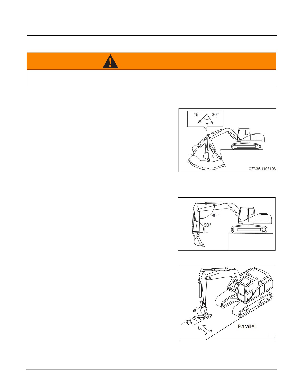
Backhoe operation
Backhoe operation is for digging an area lower than the
machine. The digging range of the arm is from 30° and 45°.
The angle may vary according to the digging depth but it is
better to keep it within the stated range.
Fig. 4-60
For maximum digging force can be obtained when the angle
between the boom and the arm and the bucket cylinder and
the bucket bracket are both 90°
Fig. 4-61
Digging a trench
Trench work can be done efficiently by using a suitable
bucket and positioning the tracks parallel to the trench line.
When digging a wider trench, excavate the sides first then
remove the middle.
Fig. 4-62
4-42
SY335 Excavator
Travel Operations
Bucket Replacement
WARNING
1. Driving a pin with a hammer can cause metal pieces to fly off leading to severe injuries.
Wear goggles, a hard hat, protective gloves and other PPE during these operations.
2. Place the bucket in a stable place after it has been removed.
3. Make sure that the surrounding area is clear of personnel when hammering any of the pins;
they could fly out and cause personal injury.
4. Do not stand behind the bucket when removing pins.
5. Take extra care not to place your foot under the bucket.
6. Do not put your finger into the pin bore during alignment.
Park the machine on a hard, level ground. This is a two person job, get someone to assist you with ground guidance
and safety when replacing the bucket.
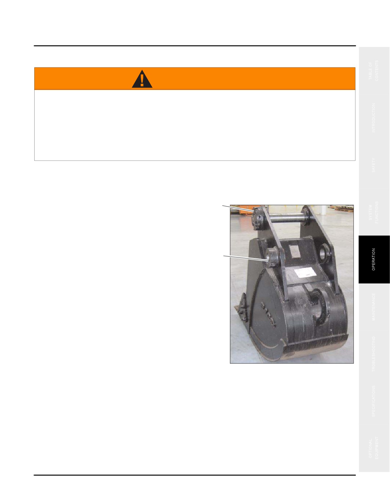
1. Place the bucket on level ground.
a
•Before removing the pin slowly lower the bucket
to a level where it just contacts the ground. If a
larger force is used to lower the bucket to the
ground, resistance could increase on the pin roll,
causing difficulties while removing it.
b
2. Remove the nuts and screws on the plate retaining arm
pin and link pin (a), take out arm pin and link pin (b),
and then remove the bucket.
Fig. 4-63
4-43
Travel Operations
SY335 Excavator
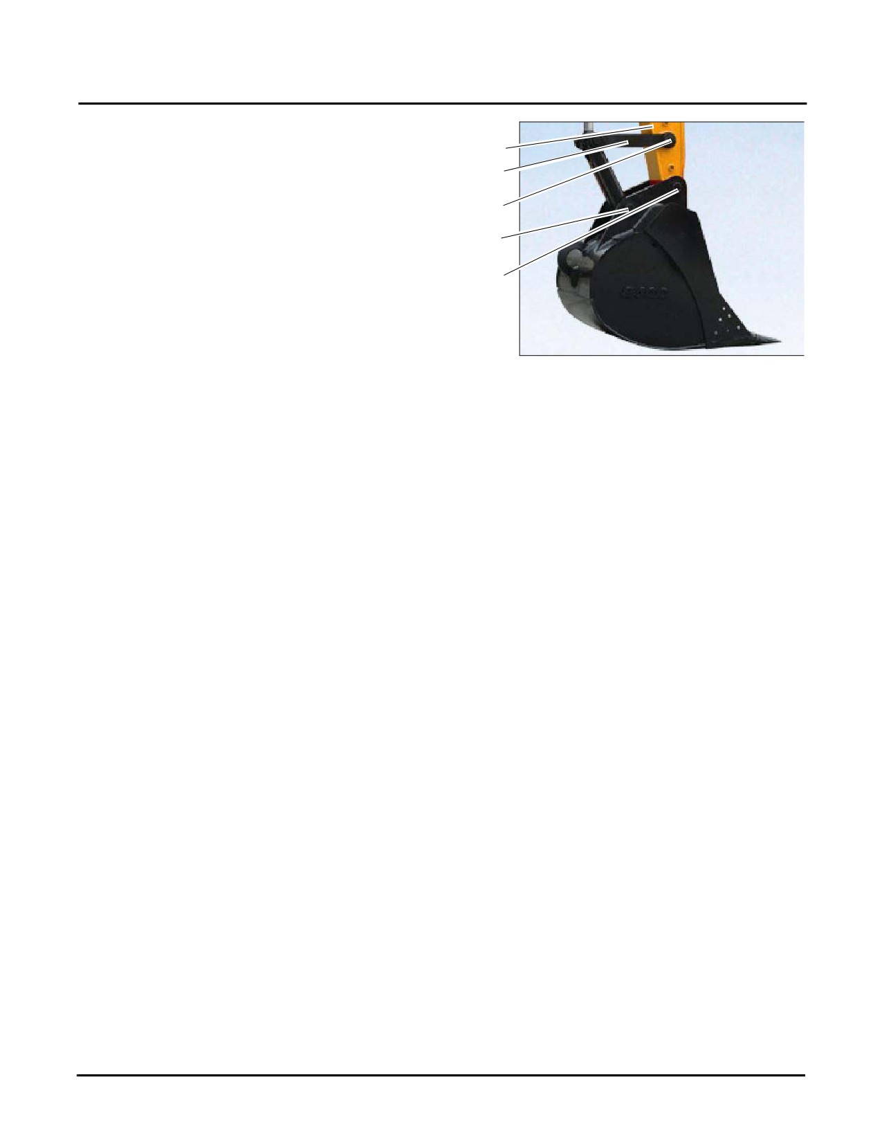
3. Align arm (c) with the bore for bucket replacement and
the link (d) with bore (e). Insert the greased pins into
c
bore (g) and bore (h) respectively.
d
NOTE: Make sure the pins are free from mud or sand
e
after removal. Both ends of the bushing are
installed with seals against dust. Be careful
g
not to damage them.
h
4. Reinstall the nuts and bolts onto the plate retaining the
pin rolls. Add grease to the pin rolls.
•Inject grease until the grease is squeezed out of the
end face.
Fig. 4-64
•Replace any broken seals when replacing a bucket.
The use of broken seals could allow sand or dust to penetrate through to the pins and causing abnormal
wear.
4-44
SY335 Excavator
End of Workday Checks
END OF WORKDAY CHECKS
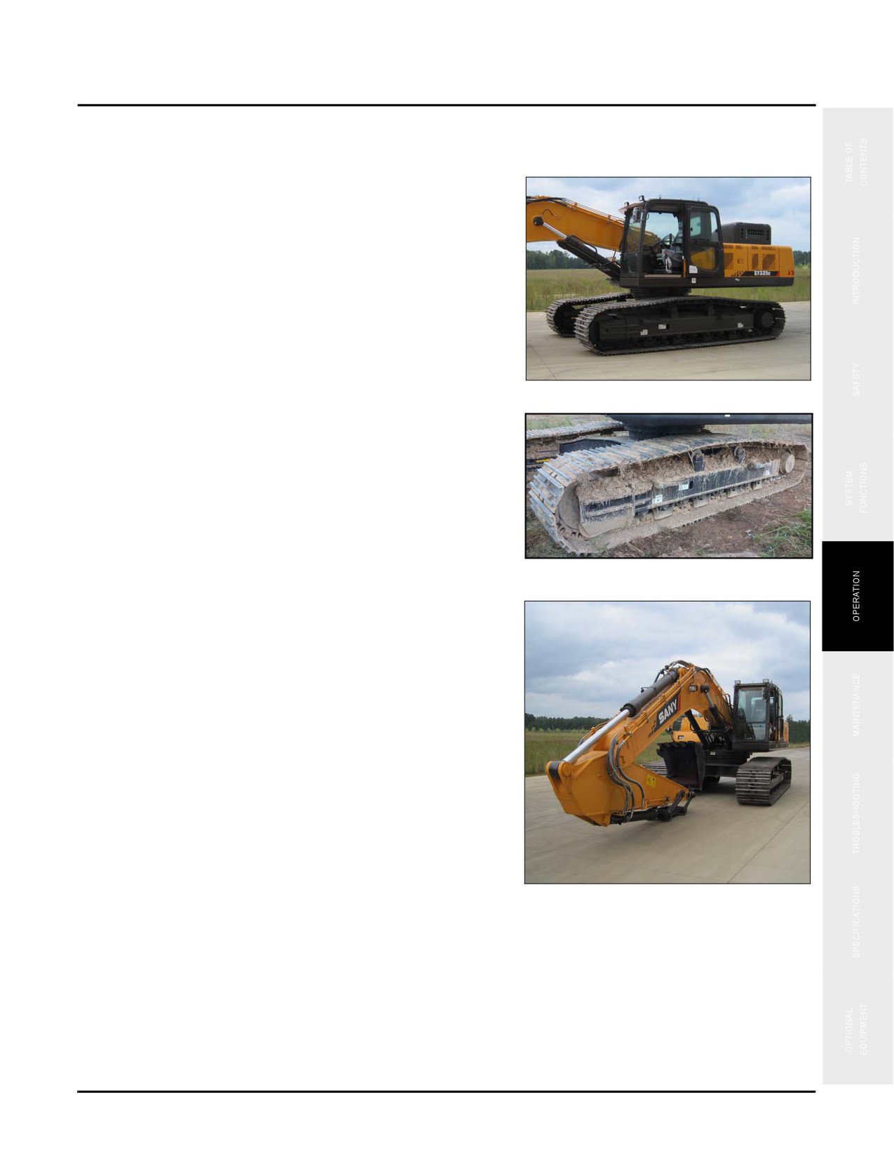
1. Check the cab for any trash or debris and deposit it into
an approved trash can.
Fig. 4-65
2. Remove all built up mud or debris on the undercarriage
or machine exterior.
Fig. 4-66
3. Inspect the machine work equipment, machine exterior,
and undercarriage for signs of fluid leaks or damage.
Fig. 4-67
4-45
Control Work Equipment
SY335 Excavator
CONTROL WORK EQUIPMENT
WARNING
1. Never allow any personnel to be within 26 ft (8m) of the rear of the machine to avoid injury.
2. Never allow any personnel to be around the machine while it is moving.
3. Be aware of all crush points on the machine and ensure that all personnel keep clear of
these areas.
All of these activities could result in serious injury or possibly death.
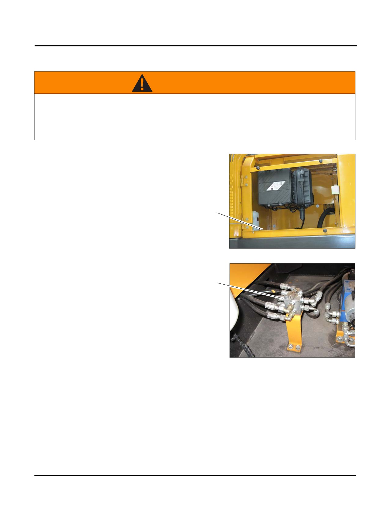
Set SAE/BHL Selector Switch
The SAE/BHL selector switch (a) is located below the
engine air cleaner inside the left side front cover.
a
Fig. 4-68
The SAE/BHL selector switch (b) swaps the control of the
boom and the arm from one joystick to the other. To go to
SAE position see step 2, to go to BHL position go to step 1. b
Fig. 4-69
4-46
SY335 Excavator
Control Work Equipment
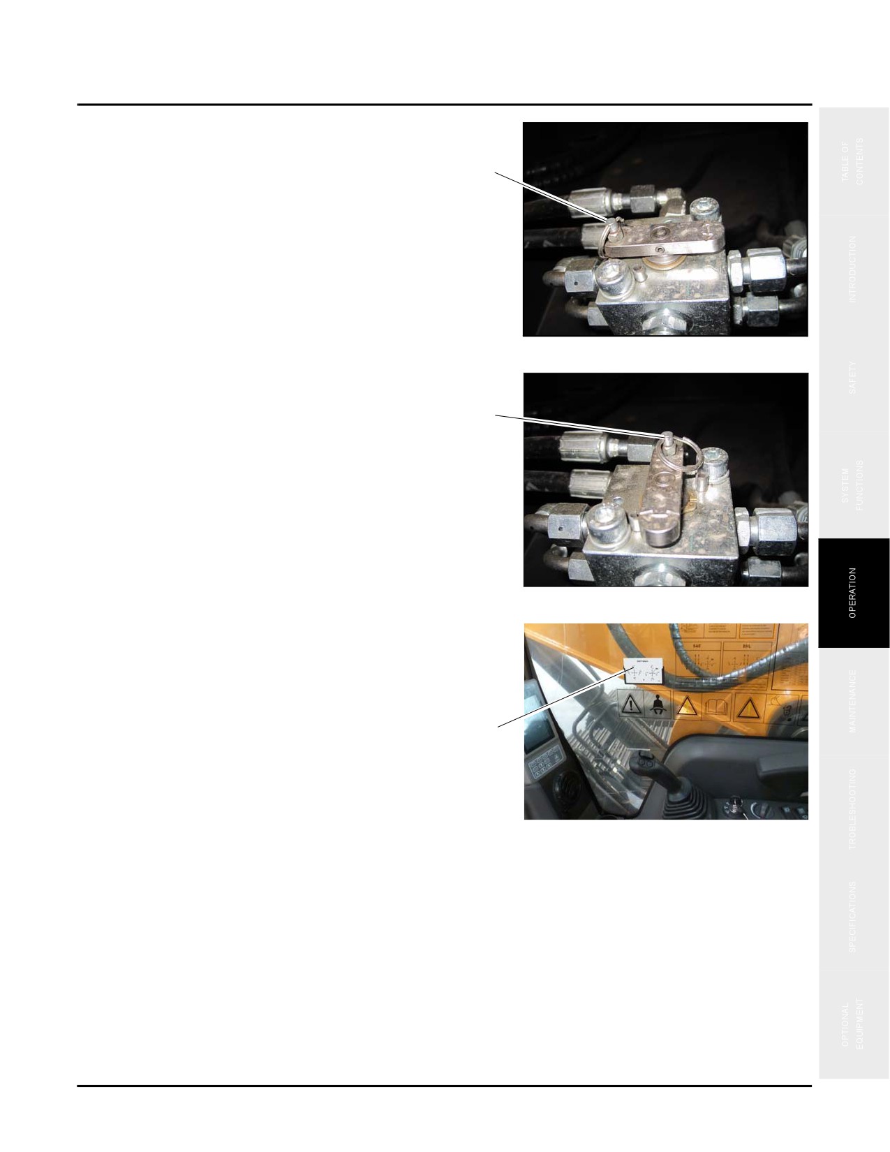
1. Pull the pin up (c) and rotate the bar to the left for BHL.
Release the pin to lock the bar in place
BHL
c
Fig. 4-70
2. Pull the pin up (c) and rotate the bar to the right for
SAE. Release the pin to lock the bar in place
SAE
c
Fig. 4-71
3. Patterns for both the SAE and BHL modes are printed
on a card (d) posted in the cab and on a decal on the
right hand window. See
“SAE Control Pattern” on
page 4-48 and See “BHL Control Pattern” on page 4-49
for additional information.
d
Fig. 4-72
4-47
Control Work Equipment
SY335 Excavator
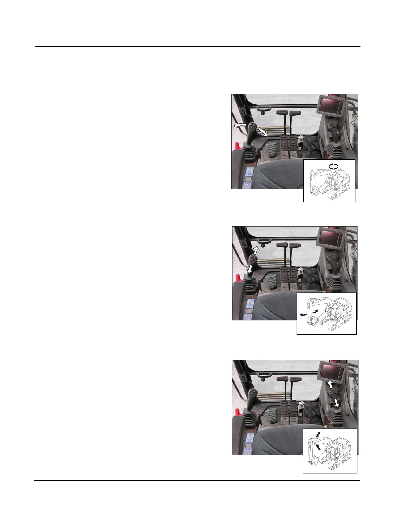
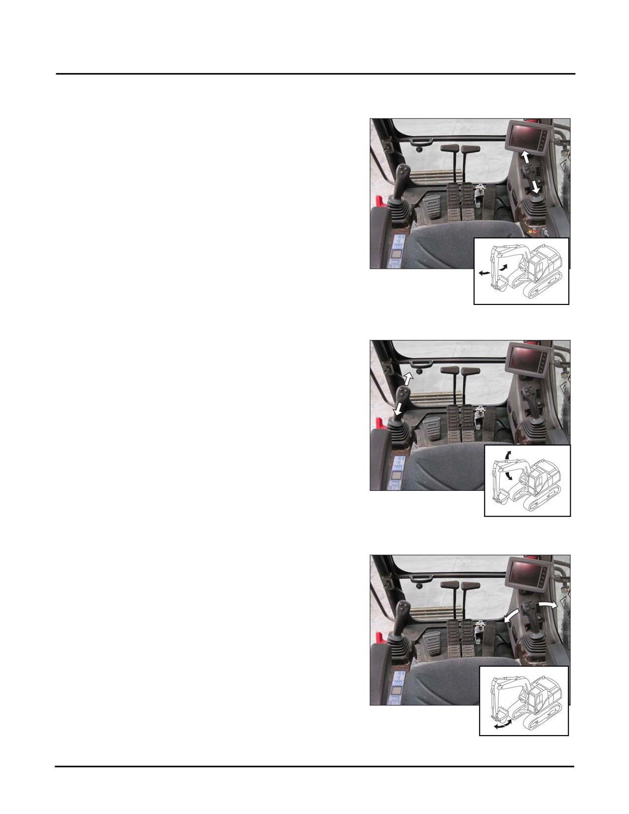
SAE Control Pattern
Swing
Moving the left joystick to the left swings the work
equipment to the left. Moving the left joystick to the right
swings the work equipment to the right.
NOTE: The swing function is the same for SAE and
BHL.
Fig. 4-73
Arm
Moving the left joystick forward extends the arm. Moving
the left joystick rearward retracts the arm.
Fig. 4-74
Boom
Moving the right joystick forward lowers the boom. Moving
the right joystick rearward raises the boom.
Fig. 4-75
4-48
SY335 Excavator
Control Work Equipment
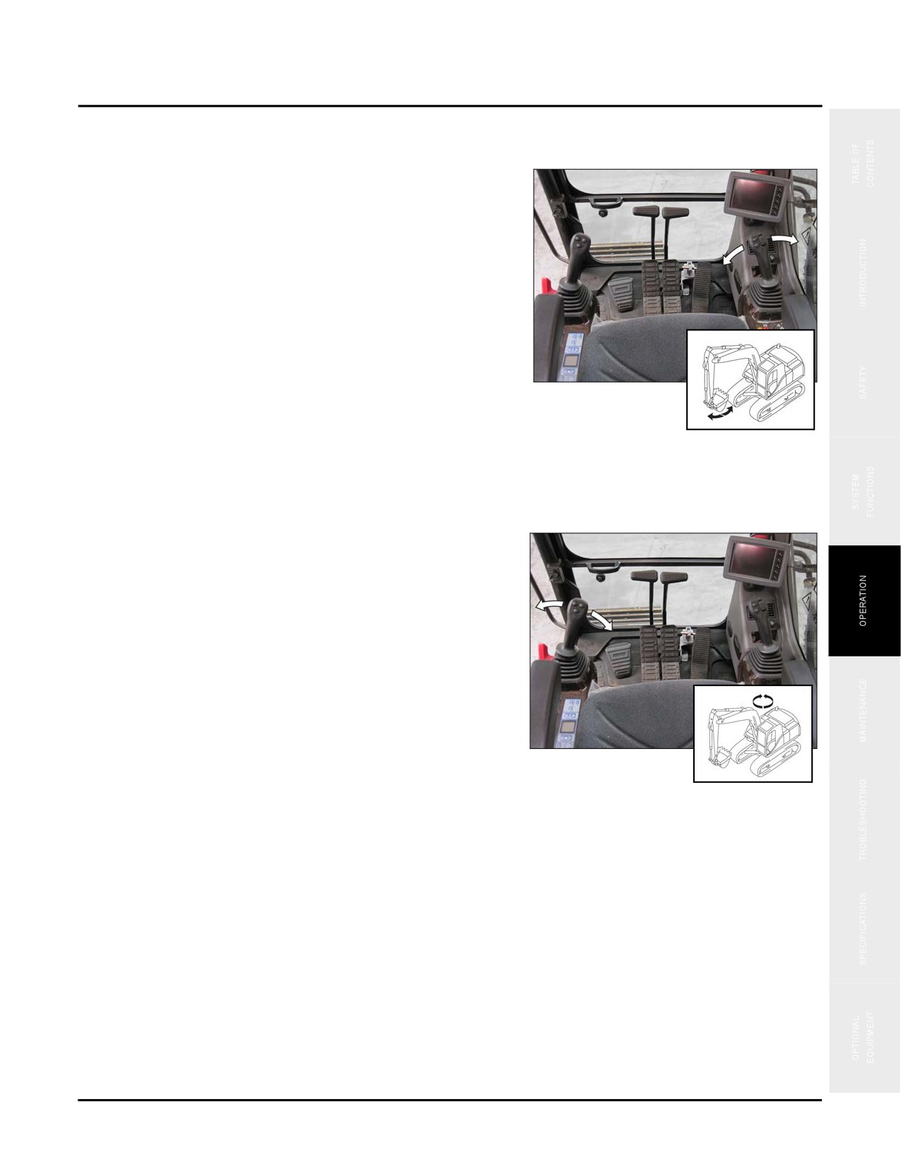
Bucket
Moving the right joystick to the left curls the bucket.
Moving the right joystick to the right dumps the bucket.
Fig. 4-76
BHL Control Pattern
Swing
Moving the left joystick to the left swings the work
equipment to the left. Moving the left joystick to the right
swings the work equipment to the right.
NOTE: The swing function is the same for ASE and
BHL.
Fig. 4-77
4-49
Control Work Equipment
SY335 Excavator
Arm
Moving the right joystick forward extends the arm. Moving
the right joystick rearward retracts the arm.
Fig. 4-78
Boom
Moving the left joystick forward lowers the boom. Moving
the left joystick rearward raises the boom.
Fig. 4-79
Bucket
Moving the right joystick to the left curls the bucket.
Moving the right joystick to the right dumps the bucket.
NOTE: The bucket function is the same for ASE and
BHL.
Fig. 4-80
4-50
SY335 Excavator
Park And Store The machine
PARK AND STORE THE MACHINE
Overnight Storage
1. Park the machine on a flat, level and stable surface
away from people, traffic or other equipment, then use
the control handles to lower the working equipment to
the ground.
2. Run the engine at idle speed (about 1000 rpm) for about
five minutes to allow for heat dissipation. Extend this
cool-down time in hot weather.
Fig. 4-81
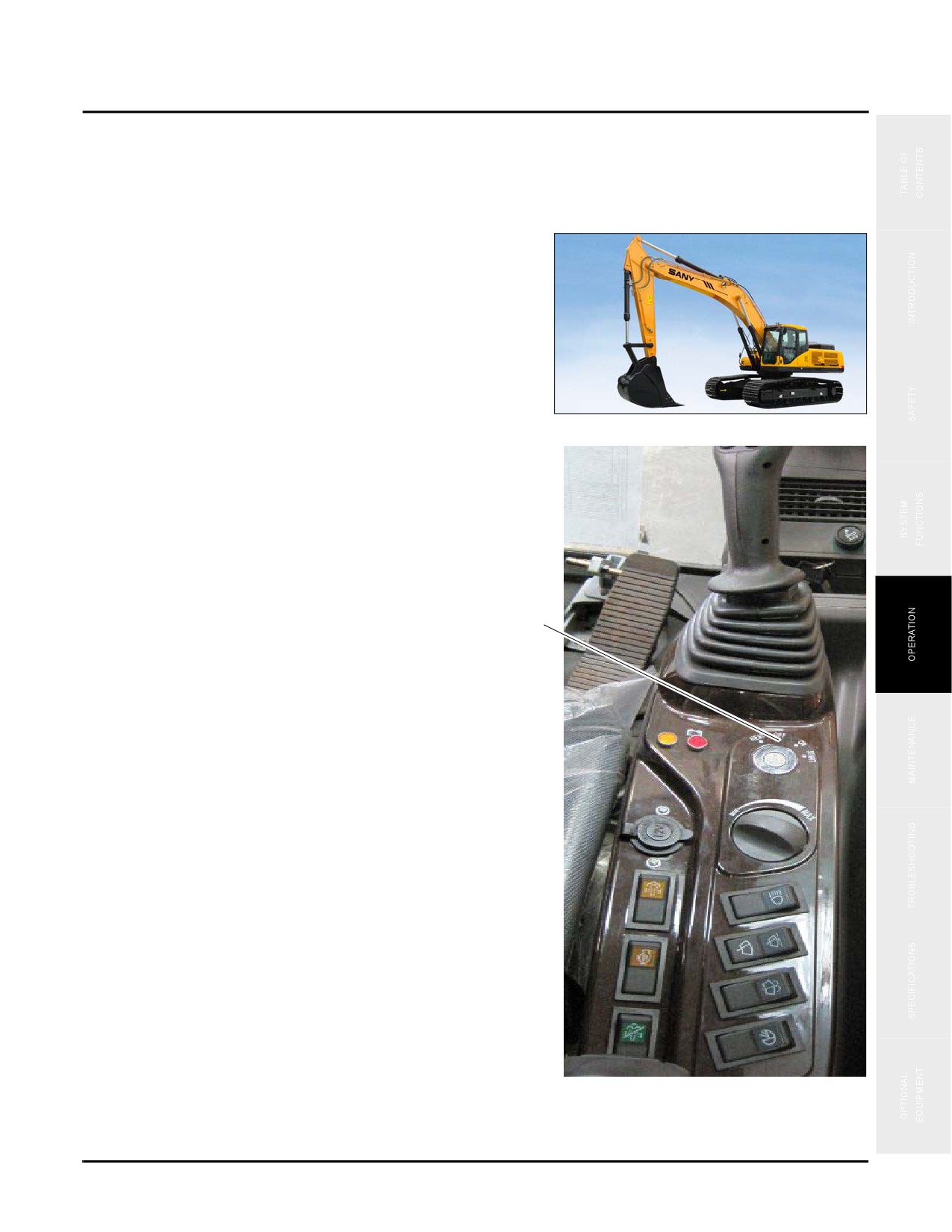
3. Turn the ignition switch (a) to the OFF position and
remove the key.
NOTE: Always remove the ignition key and take it
with you, even if you are leaving the
machine for only a moment. Keep it with
you to prevent unauthorized operation of the
machine.
a
4. Operate all controls in all directions to relieve stored
pressure within the hydraulic system.
Fig. 4-82
4-51
Park And Store The machine
SY335 Excavator
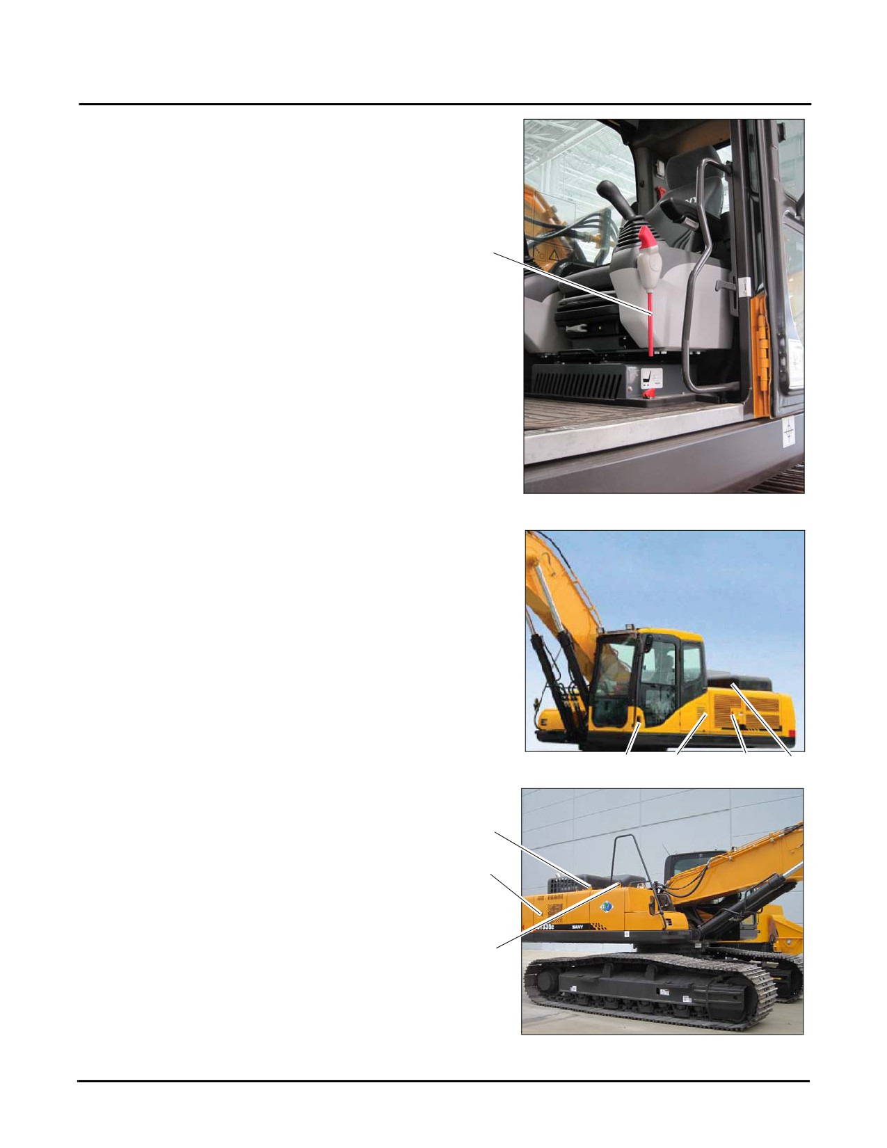
5. Set the hydraulic locking lever in the LOCKED position
(b).
6. Close and lock the windows.
7. Exit the cab.
b
NOTE: See “Mount and Dismount the Machine” on
page 4-10
8. Fill the fuel tank to the maximum level.
NOTE: See “Refueling” on page 2-25
Fig. 4-83
9. Ensure that the following items are secured and locked
on the left side.
•
Cab door (c)
•
A/C fresh air inlet door (d)
•
Left rear door (e)
•
Engine hood (g)
Fig. 4-84
c
d
e
g
10. Ensure that the following items are secured and locked
on the right side.
h
•
Hydraulic tank filler cap (h)
k
•
Right rear door (k)
•
Fuel tank cap (m)
m
Long Term Storage
Proper preparation for long term storage will reduce the
Fig. 4-85
chances for damage or deterioration of the equipment.
4-52
SY335 Excavator
Park And Store The machine
Preparation
1. Park the machine in a secure location and position the
work equipment as shown in the illustration to the right.
2. Run the engine at idle speed (about 1000 rpm) for about
five minutes to avoid increasing internal temperatures
Typical
and to allow for heat dissipation. Extend this cool-down
time in hot weather.
Fig. 4-86
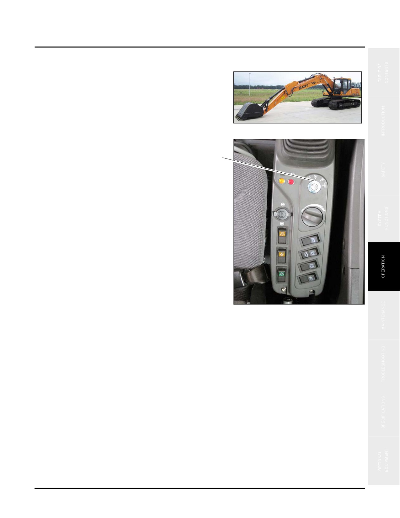
3. Turn the ignition switch (a) to the OFF position and
remove the key.
a
NOTE: Always remove the ignition key and take it
with you, even if you are leaving the
machine for only a moment. Keep it with
you to prevent unauthorized operation of the
machine.
4. Operate all controls in all directions to relieve stored
pressure within the hydraulic system.
Fig. 4-87
4-53
Park And Store The machine
SY335 Excavator
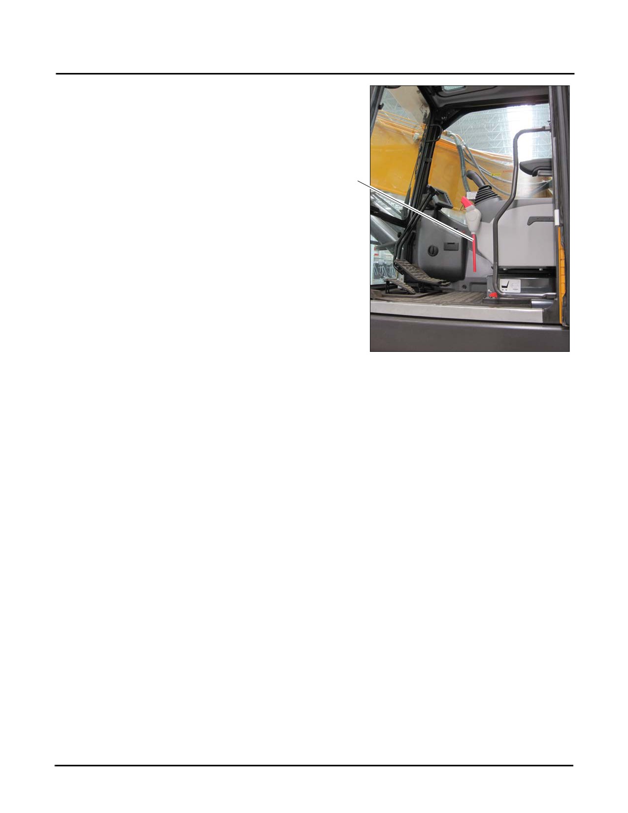
5. Set the hydraulic locking lever in the LOCKED position
(b).
6. Close and lock the windows.
7. Exit the cab.
NOTE: See “Mount and Dismount the Machine” on
b
page 4-10
8. Fill the fuel tank to the maximum level.
NOTE: See “Refueling” on page 2-25
Fig. 4-88
4-54
SY335 Excavator
Park And Store The machine
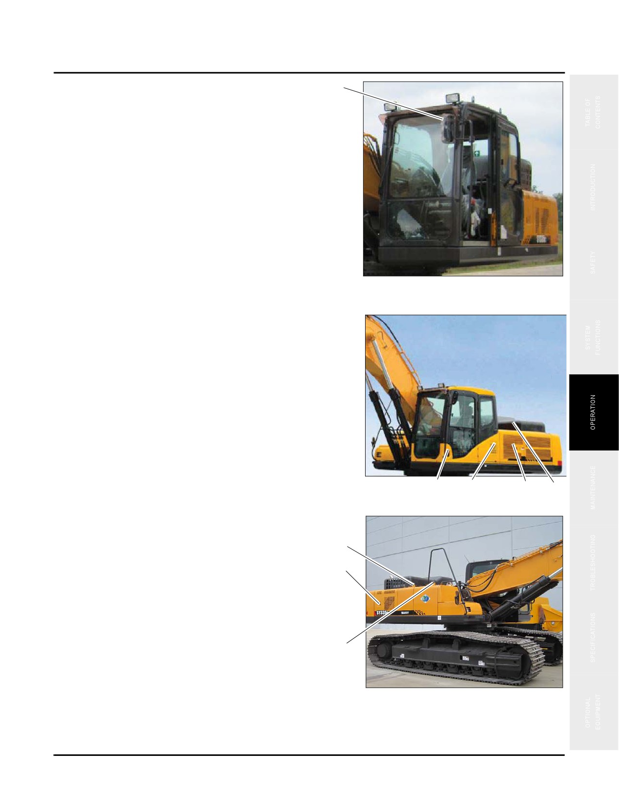
9. Pivot all mirrors (c) inward so that they are within the
c
perimeter of the machine.
Fig. 4-89
10. Ensure that the following items are secured and locked
on the left side.
•
Cab door (d)
•
A/C fresh air inlet door (e)
•
Left rear door (g)
•
Engine hood (h)
d
e
g
h
Fig. 4-90
11.
Ensure that the following items are secured and locked
on the right side.
k
•
Hydraulic tank filler cap (k)
m
•
Right rear door (m)
•
Fuel tank cap (n)
n
Fig. 4-91
12. Apply grease to any exposed parts of the piston rods.
13. Change the engine oil in accordance with engine manufacturer’s procedures.
4-55
Park And Store The machine
SY335 Excavator
14. Disconnect the battery negative terminal and reinstall the battery cover or remove the batteries and store them
in a separate location.
During Storage
WARNING
When operating equipment inside a building it is necessary to open doors and windows to
provide adequate ventilation. Failure to do so may result in severe injury.
1. Start the machine once a month.
NOTE: See “Engine Start Procedure” on page 4-30.
2. Drive the machine a short distance each month.
NOTE: See “Travel Operations” on page 4-34.
CAUTION
Wipe off all the grease off of cylinder pistons before operating the work equipment. Failure to
do so could damage the piston seals.
3. Cycle each cylinder a few times once a month to coat pistons with oil.
NOTE: See “Control Work Equipment” on page 4-46.
4. Turn on the air conditioner and allow it to run for 3 to 5 minutes each month to lubricate the compressor and
related parts.
5. Return the equipment to the proper storage location and condition.
NOTE: See “Preparation” on page 4-53.
Return to Service
1. Check the fuel and engine oil for water contamination. Drain water or replace fluids as necessary.
NOTE: See “Draining Primary Fuel Filter” on page 4-14
2. Examine the exterior of the machine for signs of rust or damage and repair as necessary.
3. Start the machine and test all operations.
NOTE: See “Engine Start Procedure” on page 4-30 and See “Before Travel” on page 4-35.
4-56
SY335 Excavator
Transport
TRANSPORT
Follow all local, state, and federal regulations and laws regarding transporting the machine. When loading or
unloading the equipment observe each of the items in the following table:
1
WARNING
1. Select a location that is firm level ground and a safe distance from any road or structure.
2. Ensure that the trailer is properly chocked to prevent any movement while loading or
unloading.
3. Use an access ramp with enough length, strength, and width to properly support the
equipment. The ramp grade should not exceed 15°.
4. Drive slowly at the junction of the ramp and the trailer. The machine may shift suddenly due
to change in center of gravity.
5. Do not move work equipment attached to the machine while loading or unloading.
6. Use a signal man to observe and alert the operator of any potential hazards.
Failure to observe these precautions could cause the machine to tip causing severe injury.
Load the machine
Contact your Sany representative for proper cab protection to be used during transport of the machine.
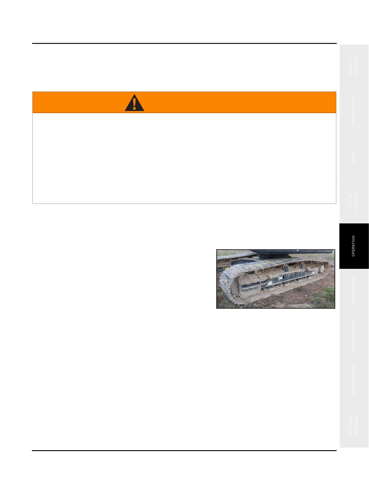
1. Clean the tracks to prevent slipping during loading.
Fig. 4-92
2. Position the machine so that the centerline of the
machine matches the centerline of the trailer.
4-57
Transport
SY335 Excavator
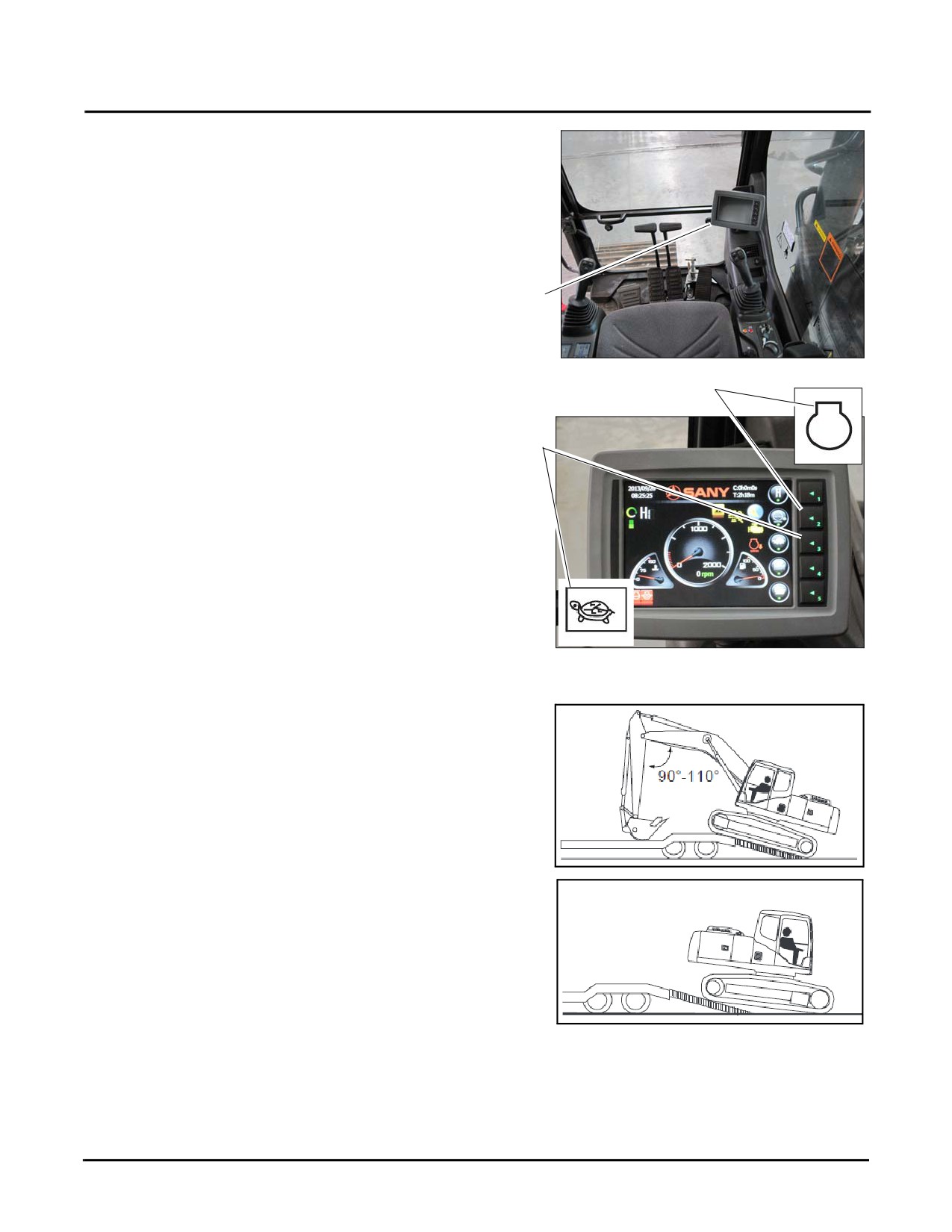
3. Press Key 2 to set the auto idle (a) on the monitor (b) to
OFF.
4. Press Key 3 to set the travel speed (c) to LOW.
b
a
c
Fig. 4-93
If work equipment is attached to the machine it should be
positioned in front of the machine during loading. If if no
work equipment is attached, back the machine onto the
trailer.
Fig. 4-94
4-58
SY335 Excavator
Transport
5. Drive the machine slowly until the tracks have full
contact with the trailer.
NOTE: See “Travel Operations” on page 4-34.
NOTE: The machine may lean forward when it passes
Fig. 4-95
over the trailer wheels.
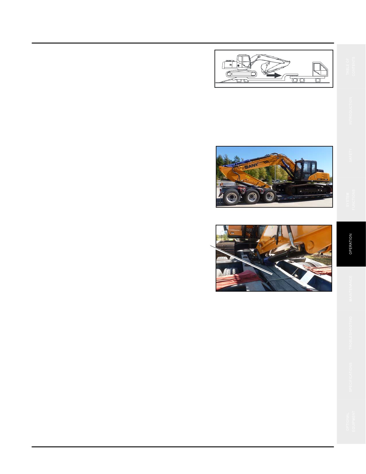
6. Raise the work equipment slowly just enough to clear the trailer.
NOTE: See “Control Work Equipment” on page 4-46
7. Swing the cab around so that the work equipment faces
the back of the trailer.
Typical
Fig. 4-96
8. Place wood on the trailer under the work equipment.
9. Fully extend the bucket cylinder arm and arm cylinder.
d
10. Lower the work equipment onto the support block (d).
11. Shut down the machine.
Typical
NOTE: See “Engine Shutdown” on page 4-32.
Fig. 4-97
4-59
Transport
SY335 Excavator
12. Exit the cab.
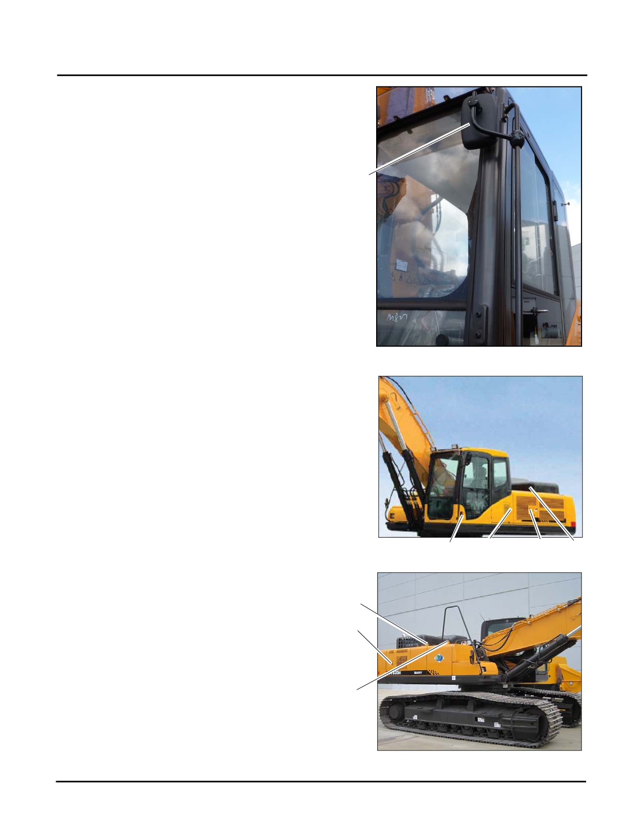
13. Pivot all mirrors (e) inward so that they are within the
perimeter of the machine.
e
Fig. 4-98
14. Close and lock the windows.
15. Ensure that the following items are secured and locked
on the left side.
•
Cab door (f)
•
A/C fresh air inlet door (g)
•
Left rear door (h)
•
Engine hood (k)
f
g
h
k
Fig. 4-99
16. Ensure that the following items are secured and locked
on the right side.
m
•
Hydraulic tank filler cap (m)
n
•
Right rear door (n)
•
Fuel tank cap (o)
o
Fig. 4-100
4-60
SY335 Excavator
Transport
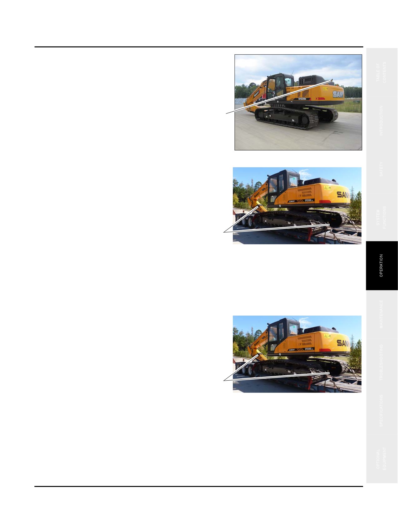
17. Cover the exhaust (p) to prevent foreign material from
entering during transport.
p
Fig. 4-101
18. Secure the machine to the trailer with suitable tie downs
(q) in accordance with all applicable laws and
regulations.
q
Typical
Fig. 4-102
Unload the machine
1. Chock the trailer to ensure that it will not move during unloading.
2. Attach or construct ramps of suitable strength, width, and length to unload the machine.
3. Remove all tie downs
(a) and blocks securing the
machine to the trailer.
4. Pivot the mirrors out to the proper settings so that the
operator has a clear view to the front and rear of the
machine.
5. Unlock and start the machine and allow it to warm up
a
Typical
fully.
Fig. 4-103
NOTE: See “Engine Start Procedure” on page 4-30.
4-61
Transport
SY335 Excavator
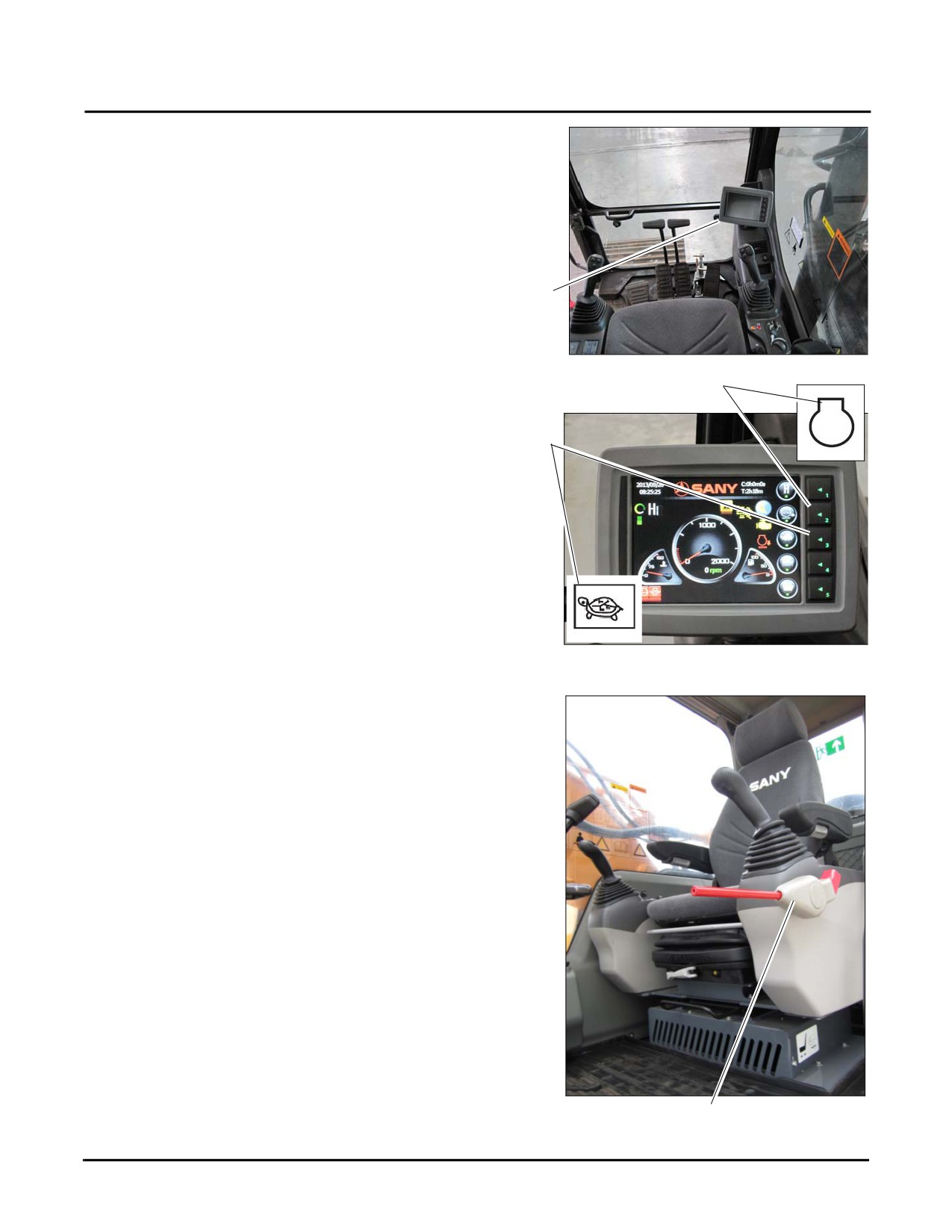
6. Press Key 2 to set the auto idle (b) on the monitor (c) to
OFF.
7. Press Key 3 to set the travel speed (d) to LOW.
c
b
d
Fig. 4-104
8. Set the hydraulic locking lever
(e) to the unlocked
position.
9. Raise the work equipment to clear the trailer.
NOTE: See “Control Work Equipment” on page 4-
46.
Typical
Fig. 4-105
e
4-62
SY335 Excavator
Transport
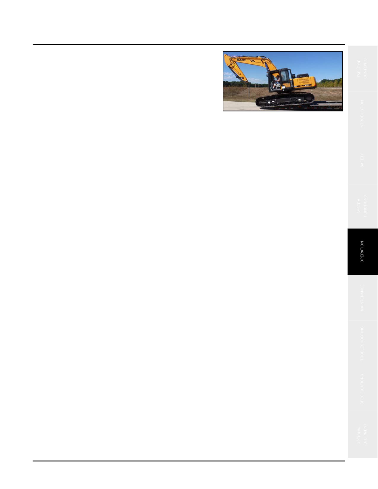
10. Drive the machine slowly off the trailer.
NOTE: See “Travel Operations” on page 4-34.
NOTE: When unloading off the back of the trailer stop
the machine when it is directly over the rear
Typical
wheels and level. Position the work equipment
so that the angle between the arm and the
Fig. 4-106
boom is 90 to 110°.
11. Lower the bucket to the ground and move slowly down the ramp operating the boom and arm inward to
provide support as the machine moves forward off the ramp.
12. Park the machine in the desired location.
4-63
Transport
SY335 Excavator
This Page Intentionally Left Blank
4-64
SY335 Excavator
Maintenance
Maintenance
Maintenance Information
5-4
Checks Before Maintenance
5-4
Checks After Maintenance or Repairs
5-5
Hour Meter Reading
5-5
Genuine Sany Replacement Parts
5-5
Sany-Approved Lubricants
5-5
Windshield Washer Fluid
5-5
Grease
5-5
Oil and Filter Inspection
5-6
Welding on the Machine
5-6
Inventory Your Tools and Parts
5-6
Cleaning Parts or the Machine
5-6
Adverse Work Site Conditions
5-6
Covers and Locks
5-7
Hydraulic Hoses, Lines or Components
5-7
Third-Party Inspection Requirements
5-7
Inspection and Maintenance in Severe Environments
5-7
Operation in Mud, Rain or Snow
5-7
Operation Near Ocean (Salt Air) Environments
5-7
Dusty Environments
5-7
Rocky Ground Surface
5-8
Cold Environments
5-8
Other Weather Environments
5-8
Torque Values
5-9
Fluids & Lubricants
5-11
Fuel
5-11
Engine Oil
5-13
Lubricants
5-13
Daily Maintenance
5-14
Check
5-15
Safety, Operation & Maintenance Manual
5-15
Operating Functions
5-15
Safety, Operation & Maintenance Manual — November 28,
2013
5-1
Maintenance
SY335 Excavator
Fire Extinguisher and Escape Tool
5-18
Backup Camera
5-18
Engine Oil Level
5-19
Pump Mounting Bolts
5-20
Fuel Level
5-21
Engine Coolant Level
5-21
Engine Serpentine Belt
5-22
Slewing Gearbox
5-24
Hydraulic Oil Tank
5-25
Hydraulic Line Connections
5-26
Electrical System
5-28
Air Conditioner
5-30
Idler Wheel
5-33
Sheet Metal
5-34
Decals
5-34
Drain
5-35
Draining the Primary Fuel Filter
5-35
50 Hours of Maintenance
5-37
Change
5-38
Engine Oil and Filter - Initial
5-38
Check
5-42
Air Intake System
5-42
Muffler and Exhaust System
5-43
Hydraulic Hoses
5-44
Batteries
5-45
Crawler Shoe Connecting Pins
5-48
Crawler Support Roller Mounting Bolts
5-48
Crawler Gearbox Oil Level
5-49
Crawler Drive Sprocket Mounting Bolts
5-50
Track Tension - Initial
5-51
Lubricate
5-54
Slewing Turntable Bearing
5-54
Work Equipment
5-56
250 Hours of Service
5-61
Change:
5-62
Engine Oil and Filter
5-62
Hydraulic Tank Return Filter Elements — Initial
. .5-62
Hydraulic Pilot Line Filter Element — Initial
5-64
Hydraulic Oil - Breaker only at 400 Hours
5-65
Check
5-65
Air Conditioner Compressor
5-65
Air Filter
5-67
Crawler Assemblies
5-70
Track Tension
5-71
Fuses
5-71
Windshield Washer and Window Wipers
5-72
Handrails and Steps
5-73
Access Panels and Locks
5-73
500 Hours of Service
5-74
Change
5-75
Primary Fuel Filter
5-75
5-2
Safety, Operation & Maintenance Manual — November 28,
2013
SY335 Excavator
Maintenance
Coolant Filter
5-77
Slewing Gearbox Oil
5-78
Hydraulic System Breather Filter
5-79
Check
5-80
Radiator, Oil Cooler, and AC Condenser Fins
5-80
Air Conditioning Fresh Air and Recirculation Air Filters
5-82
Slewing Gearbox Bolts
5-84
Hydraulic Hoses
5-85
Hydraulic Pump
5-85
Upperworks and Lowerworks
5-86
Final Drive
5-87
Swing Pinion Gear Grease Level
5-88
Lubricate
5-89
Work Equipment
5-89
1,000 Hours of Service
5-90
Change
5-91
Hydraulic Tank Return Filter
5-91
Hydraulic Pilot Line Filter
5-91
Check
5-91
Engine Exhaust Pipe Clamps
5-91
Accumulator Nitrogen Pressure (Breaker only)
5-92
Fuel Tank Strainer
5-94
Fuel Lines
5-95
2,000 Hours of Service
5-96
Change
5-97
Hydraulic Oil
5-97
Engine Coolant
5-102
Final Drive Oil
5-105
Check
5-106
Hydraulic Hoses
5-106
Accumulator Gas Pressure
5-106
Machine Storage
5-107
Short-Term Storage (Less than 30 days)
5-107
Long-Term Storage (Longer than 30 days)
5-107
WARNING
Read and understand the safety precautions
and instructions in this manual before reading
this section and performing any maintenance
procedures on this machine. Failure to do can
cause serious injury, death or property
damage.
5-3
Maintenance Information
SY335 Excavator
MAINTENANCE INFORMATION
Do not perform any maintenance and/or repairs not
authorized in this Safety, Operation & Maintenance Manual
or the Service Manual for this machine. Always observe and
follow all safety precautions and use the proper tools when
performing any maintenance procedures.
Checks Before Maintenance
Read and understand the Safety section of this manual —
Fig. 5-1
including the Lockout/Tagout procedure —before
proceeding with any inspection or maintenance procedures.
NOTE: See “Lockout/Tagout Procedures” on page 2-21.
Observe and understand these points to ensure your safety:
•
Do not perform any maintenance not authorized in this operator’s manual maintenance section for this
machine. If maintenance is required that is not listed within this manual please contact your Sany
distributor before proceeding.
•
Avoid working on the machine while the engine is running unless required to do so in the procedure. If the
engine must remain running during a procedure, always have a person in the cab who can correctly operate
the machine and who is in clear contact with you at all times.
•
Contact your Sany distributor if you are unable to perform the procedures listed in this manual or if
additional procedures are required.
•
Always use the proper tools when performing any maintenance procedures.
•
Obtain the maintenance record for this machine before proceeding with any repair work.
•
Always use the maintenance record for this machine to keep a daily record of the hour meter reading, then
refer to it when determining your schedule of maintenance procedures.
•
Always use genuine Sany parts, coolants and lubricants when maintaining this machine. Failure to do so
may result in premature system or component failure.
•
Use only the grease types listed in “Lubricating Grease/Temperature Data” on page 5-12 when lubricating
the machine.
•
If any access covers must be open when working on this machine, be sure those covers are properly
supported.
5-4
SY335 Excavator
Maintenance Information
Checks After Maintenance or Repairs
Always do the following after performing any maintenance to the machine.
With the engine off:
•
Be sure you have completed all the steps in the maintenance or repair of the machine.
•
If necessary, have a coworker inspect your work for correct and proper completion.
With the machine running:
•
Check for any leakage or overheating in the system you have serviced.
•
Be sure there are no abnormal sounds coming from the engine or hydraulic system and nothing is loose.
Hour Meter Reading
Keep track of the hour meter reading on a daily basis. Confirm meter readings with the required maintenance
schedule listed in this manual.
Genuine Sany Replacement Parts
Use genuine Sany replacement parts when repairing or replacing a part on the machine. Failure to do so may result
in premature system or part failure.
Sany-Approved Lubricants
Never substitute lubricants or coolants with aftermarket products. System failure or the service life of the machine
may be shortened. Always use approved Sany coolants and lubricants. Never mix lubricants of different brands.
System damage or premature failure may result.
Windshield Washer Fluid
Use automotive windshield washer fluid only. Never use flammable liquids that could ignite or explode. Never use
tap water, dirty water or fluids that could freeze, clog or damage the system.
Grease
Sany recommends Shell Alvania Grease EP (LF) 2 designed for:
•
Heavy duty bearings and general industrial lubrication.
•
Heavy duty plain and rolling element bearings operating under severe conditions, including shock loading
in wet environments.
•
Operation over 212°F (100°C) for bearings operating at 75% of the maximum rated speed (can withstand
up to 248°F/120°C intermittently)
5-5
Maintenance Information
SY335 Excavator
Oil and Filter Inspection
Always inspect the drained oils and filters for signs of metal particles and foreign material. Contact your Sany
distributor for an oil analysis test if any abnormality is found in the filter or oil.
Welding on the Machine
NOTE: Please contact your Customer Service Department for proper guidance on any welding
being attempted.
Personnel welding on the machine must be fully qualified and certified to use the processes and equipment they
may operate in making these repairs. Customers are responsible for the structural integrity of any completed repair.
Sany strongly recommends against welding on chords or connectors, and fine grain hi-strength steels. Components
should be replaced with Sany-authorized parts if they are damaged or modified.
Inventory Your Tools and Parts
After performing maintenance or repairs to the machine, always take time to inventory your tools, parts used and
nuts and bolts to be sure none of these items were left on or inside the machine. Failure to do so could result in
unexpected failure or damage to the machine.
Cleaning Parts or the Machine
•
Never clean the machine with caustic chemicals or steam cleaners. Damage to the paint or operating
systems could result. Instead, use mild soaps and a pressure washer to clean the machine. Always protect
electrical parts when cleaning the machine.
•
Never flood or pressure-wash the inside of the operator’s cab. Damage to the cab electrical system could
result.
•
Use only nonflammable cleaning solvents. Never use caustic or flammable liquids to clean parts or
systems.
Adverse Work Site Conditions
If the machine will be operating under dusty or adverse conditions, Sany recommends that you:
•
Clean the radiator and oil cooler core to avoid any clogging.
•
Clean or replace the fuel filters more frequently than recommended later in this section.
•
Check and clean any electrical components to avoid any accumulated corrosion.
•
Check and clean any areas where extreme heat is present, such as the exhaust system, manifold and
turbocharger.
5-6
SY335 Excavator
Maintenance Information
Covers and Locks
When servicing the machine with the covers open, be sure they are properly supported in place. Also be sure the
covers close tightly and latch securely in place. If a lock is present, be sure the lock is properly latched for security.
Hydraulic Hoses, Lines or Components
Inspect hydraulic oil for any signs of contaminant. Contact your Sany distributor for an oil analysis test or
replacement if any abnormality is found. Inspect the filters for signs of metal particles and foreign material and
replace the abnormal ones. Failure to do so may affect the efficiency of hydraulic oil.
Third-Party Inspection Requirements
By law (OSHA) all employers shall designate a competent person (third-party) to inspect all machinery and
equipment prior to and during use, ensuring the equipment is in safe operating condition. All deficiencies should be
repaired, or defective parts replaced, before continued use.
Annual inspections of all hoisting machinery shall be made by a third-party or a government or private agency
recognized by the U.S. Department of Labor. Owners are required to maintain a record of the inspection to include
the date and results for each hoisting machine and piece of equipment used.
Inspection and Maintenance in Severe Environments
Operation in Mud, Rain or Snow
•
Before operation: Inspect each plug and pin for looseness.
•
After operation: Clean the crane, inspect for missing or loose bolts and nuts, and add oil and lubricating
grease as needed.
Operation Near Ocean (Salt Air) Environments
Before operation: Inspect each plug and pin for looseness. Apply grease where rust is found, especially at
connecting rods and control levers.
After operation: Thoroughly wash away the salt residue, apply grease where rust is found, and perform
maintenance carefully on the electric components to prevent corrosion.
Dusty Environments
•
Air filter: Clean the filter cartridge and dust collector frequently.
•
Radiator: Clean the radiator core frequently to prevent blockage.
•
Fuel equipment: Clean the filter parts frequently.
•
Electric components: Clean the starter and contact surface of sensor carefully.
5-7
Maintenance Information
SY335 Excavator
Rocky Ground Surface
Crawlers should be set slightly loose from what is required for other environments. Crawler track tension is
normally 20 - 45 mm (0.75 - 1.75 in.), Sany recommends that you loosen the crawler track tension to 45mm/1.75
inches for rocky ground surfaces only. Inspect the crawlers for damage, such as cracks, abrasions and scars on the
travel mechanism and loose or missing bolts or nuts.
Cold Environments
In extreme cold environments (32F/0C) lubricate only with the oils shown in Engine Oil Viscosity/Temperature
Data page 5-12. Sany recommends the use of fuels identified in Fluids and Lubricants, page 5-11 for extreme cold
environments. Prior to staring the engine, ensure that the battery is fully charged and that the battery case and the
cables have not cracked.
Other Weather Environments
During the maintenance and re-installation of track rollers, the direction should be reversed to prolong the lifetime
of guide rails. This is much like rotating tires on a automobile for better tread wear. When reinstalling the rollers
rotate them 180 degrees about the vertical axis from the orientation they were in when initially removed.
Inspect all items listed in this section to ensure the safe use of the chine before the initial use, or before use after
maintenance or repair. Remember to include the results in the Maintenance Log. In addition to the previously
described inspection items, clean and lubricate all components after a long-term (more than two weeks) shutdown
of the machine.
Based on past experience and suggestions by lubricating oil suppliers, the lubricating intervals listed in the
following tables apply only to “normal operating conditions”. In harsh environments, including dusty and corrosive
air, abnormal external temperature, extremely heavy overload, frequent operating times, long-time duty cycle etc;
lubricating intervals should be shortened. Always follow the schedule described in this manual until enough
experience is obtained to establish a new schedule.
NOTE: If there is evidence of overheating of bearings or bushings, loose parts or rust during regular
inspection; increase the frequency of lubrication.
5-8
SY335 Excavator
Maintenance Information
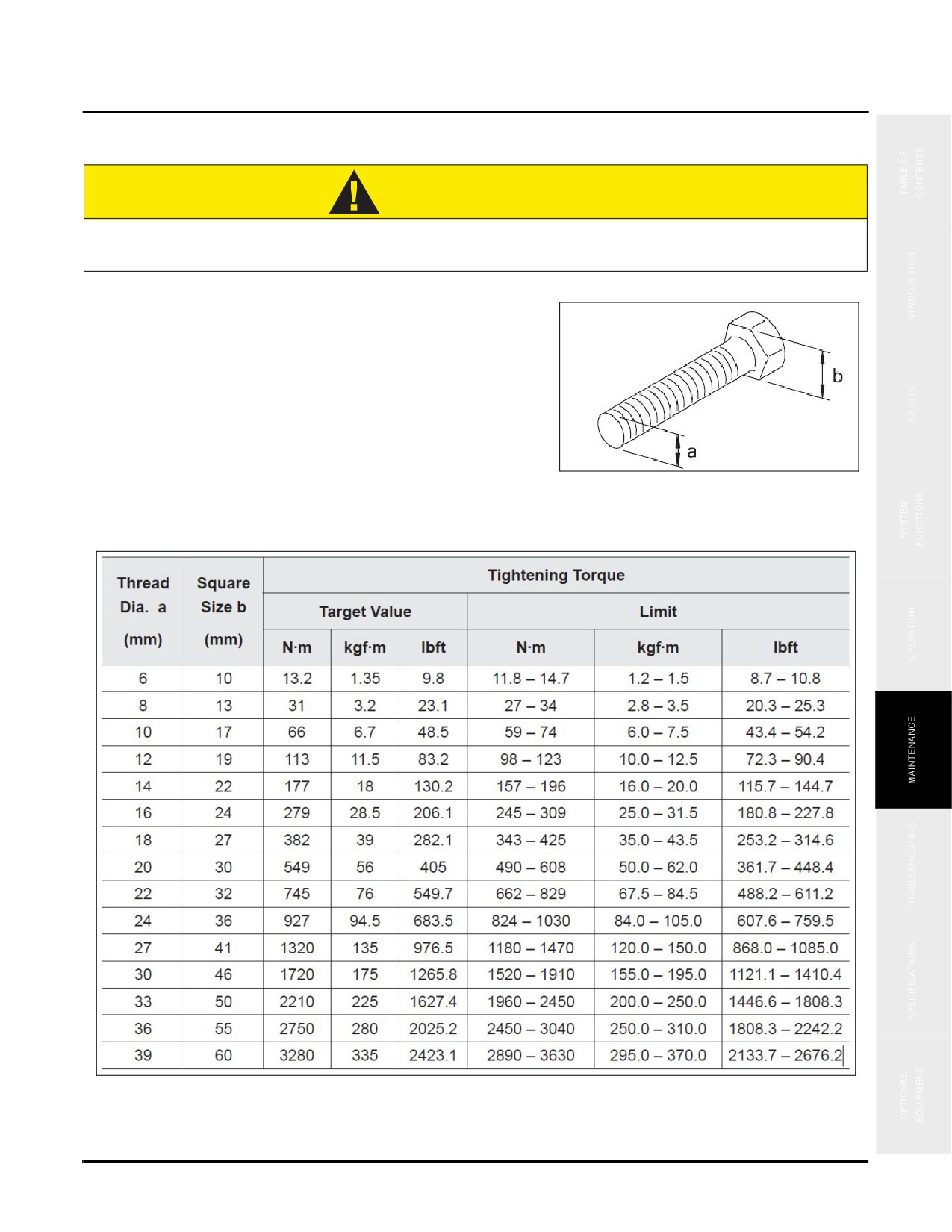
Torque Values
CAUTION
Nuts, bolts or other parts not tightened to specific torque values may lead to loose or
damaged parts, resulting in machine failure and operating troubles.
Always refer to this chart if the tightening torque value is
not listed or specified in the procedure. Unless specified
otherwise, the metric nuts and bolts shall be tightened to the
values given in the following table. The tightening torque is
determined by the width of screw cap or nut. In replacement
of the bolts or nuts, use Sany genuine parts of equivalent
size.
Fig. 5-2
5-9
Maintenance Information
SY335 Excavator
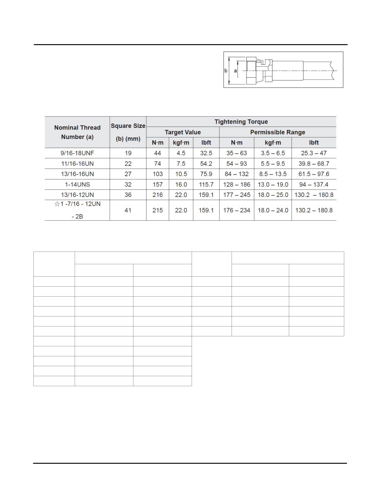
Hydraulic hoses are tightened according to the torque
values shown below:
Fig. 5-3
NOTE: The item marked with ☆ is used for tightening the hose on top of the swivel joint.
Tightening Torque Value
Tightening Torque Value
Port
Tube
Fitting
Fitting
N•m
lbf•ft or (lbf•in.)
N•m
lbf•ft or (lbf•in.)
M14
34.3 ± 5
25 ± 4
G1/8
16.7 ± 2
(148 ± 18)
M16
54 ± 5
40 ± 4
G1/4
36.7 ± 2.5
27.1 ± 2
M18
70 ± 10
52 ± 7
G3/8
73.5 ± 5
54 ± 4
M20
93 ± 10
69 ± 7
G1/2
107.8 ± 7.8
80 ± 6
M22
125 ± 10
92 ± 7
G3/4
161.7 ± 14
119 ± 10
M24
142 ± 20
105 ± 15
G1
220 ± 25
162 ± 18
M24
68.6 ± 10
51 ± 7
M26
180 ± 20
133 ± 15
M20
49 ± 5
36 ± 4
G3/8
68.6 ± 20
51 ± 15
G3/4 (A)
1,661.7 ± 14
1,226 ± 10
5-10
SY335 Excavator
Fluids & Lubricants
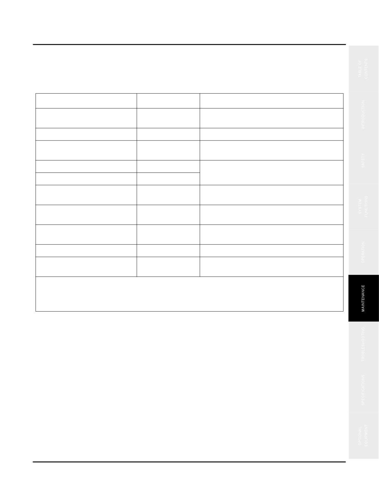
FLUIDS & LUBRICANTS
Always use Sany-recommended lubricants, coolants and filters. Never mix fluids of different brands and never
overfill the system you are servicing. Failure to follow these standards will reduce machine life.
Location
Approx. Capacity*
Lubricant/Coolant
Engine:
See “Engine Oil Viscosity/Temperature Data” on
7.67 gal. (29L)
QSL9 CM2250 EPA Tier4
page 5-12
Fuel system
137 gal. (520 L)
#2 Diesel Fuel.
Any brand meeting the Cummins® Engineering
Engine Cooling System
12.5 gal (48L)
Standard 14603.
Slewing gearbox
1.3 gal. (5 L)
See “Industrial Gear Oil/Temperature Data” on
page 5-12
Crawler gearbox/Final Drive
1 gal. (4 L)
Hydraulic system (including tank)
See “Hydraulic Oil/Ambient Temperature Data”
108.3 gal. (410 L)
on page 5-13
Slewing bearing
See “Lubricating Grease/Temperature Data” on
75 lb (34 kg)
page 5-12
Anaerobic sealant
NA
Any anaerobic sealant having properties similar to
LOCTITE 243 (Blue)
Spray lubricant
NA
Any lithium grease based spray lubricant
Mineral spirits
NA
Type II odorless mineral spirit and/or Class 1
(high flashpoint)
* The capacities in this table are approximations. For exact capacities, please use the inspection points,
inspection plugs, dipsticks, and the sight glasses.
Sany is not responsible for damage caused by using unauthorized lubricants and coolants.
Fuel
Sany recommends the use of #2 diesel fuel for all normal operations. Use of #1 diesel fuel in a blend with #2 diesel
is normally mandated by local authorities in cold weather environments for more efficient operations.
NOTE: Sany does not recommend the use of any diesel fuel with a Cetane level less than 40.
NOTE: Do not use gasoline, kerosene or any unapproved fuels in the fuel system. If fuel waxing or bacteria
occurs in the fuel system, contact your Sany distributor for help. Never dilute fuels, damage to the
fuel injection system may result from this action
5-11

Fluids & Lubricants
SY335 Excavator
Table 5-1: Engine Oil Viscosity/Temperature Data
Temperature
°F (°C)
-22
-4
5
32
50
68
86
104
122
(-30)
(-20)
(-15)
(0)
(10)
(20)
(30)
(40)
(50)
Oil Type
SAE15W-40
SAE10W-30
SAE5W-30
SAE 5W-40
SAE 40W
NOTE: Due to its comparatively better lubricating characteristics (including improved oil consumption,
engine operation in frigid climates, and continued lubrication in high temperatures), SAE 5W-40 is
recommended for a majority of climates. In some circumstances, short-term use of low viscosity
engine oil in cold temperatures (below 23°F / -5°C) is acceptable, long-term use can reduce engine
life.
Table 5-2: Lubricating Grease/Temperature Data
Temperature
°F (°C)
Summer
Winter
Grease Type
#2 molybdenum disulfide
lithium-based grease
#3 molybdenum disulfide
lithium-based grease
NOTE: The maximum operating temperature of lubricating grease must be 20°-30º C lower than its dropping
point.
Table 5-3: Industrial Gear Oil/Temperature Data
Temperature
°F (°C)
-4
14
32
50
68
86
104
122
(-20)
(-10)
(0)
(10)
(20)
(30)
(40)
(50)
Oil Type
220LS2
NOTE: Short-term use of low viscosity engine oil in cold temperatures (below 23°F / -5°C) promotes engine
life; long-term use of low-viscosity engine oil can reduce engine life.
5-12
SY335 Excavator
Fluids & Lubricants
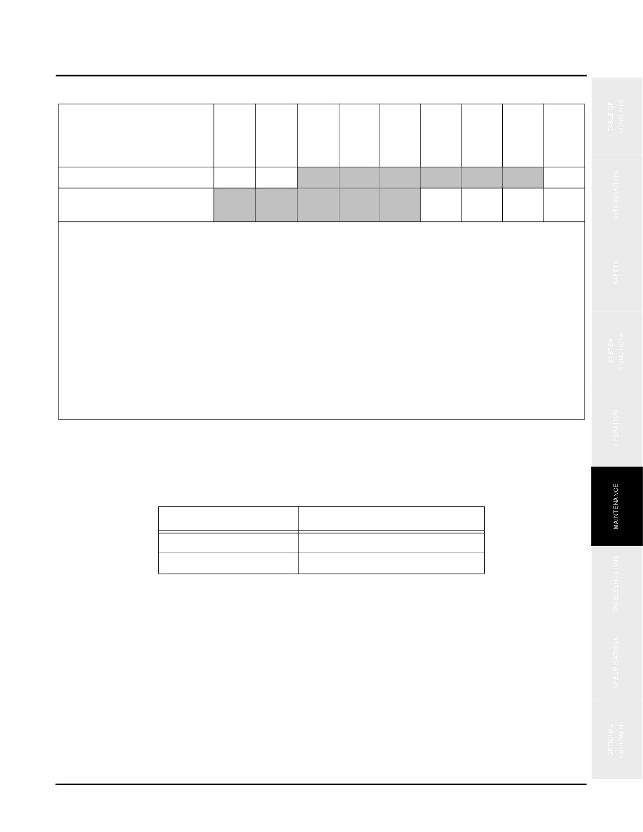
Table 5-4: Hydraulic Oil/Ambient Temperature Data
Temperature
°F (°C)
-22
-4
14
32
50
68
86
104
122
(-30)
(-20)
(-10)
(0)
(10)
(20)
(30)
(40)
(50)
Oil Type
L-HM46 antiwear hydraulic oil
L-HV32 low temperature
antiwear hydraulic oil
NOTES:
1. Select proper hydraulic oil based on local operating climate and conditions:
• Use L-HM46 antiwear hydraulic oil in generally temperate climates.
• Use L-HV32 low temperature antiwear hydraulic oil (pour point is -43.6° F (-42° C) in generally arctic areas
where ambient temperatures during operation can reach -22° F (-30° C).
2. To prevent damage to the hydraulic system, perform the following warm-up procedure in ambient
temperatures below 32° F (0° C):
(a) Start the engine and run it at idle speed for 7 - 10 minutes; then increase the engine speed to 1,000 -
1,200 rpm and perform only no-load traveling for at least 30 minutes or until the hydraulic oil temperature
is at least 68°F (20°C).
(b) Proceed with normal operation only after completing warm-up as described above or else adjust the
warm-up period according to the ambient temperature. During normal construction operation, take care to
operate the controls slowly and observe the traveling system for any signs of trouble. Operation with oil
temperature of 68° F (20° C) or below may damage the hydraulic system.
Engine Oil
Engine oil change intervals will vary according to the amount of sulfur in the fuel. Change engine oil according to
the following table:
Fuel Sulfur Content
Engine Oil Change Interval
0.5 to 1.0%
1/2 of the regular interval
Above 1.0%
1/4 of the regular interval
Lubricants
Sany recommends using only those lubricants listed in “Fluids & Lubricants” on page 5-11 and does not
recommend commercially available lubricants or additives other than what is listed in this chart. Note that
commercially available lubricants and additives may cause harm.
NOTE: Contact your Sany distributor for assistance if the machine will be operated in subzero temperatures
where the aid of an auxiliary heating device is needed.
5-13
Daily Maintenance
SY335 Excavator
DAILY MAINTENANCE
NOTICE
Failure to perform the following procedures when and how directed will result in shortened
service life of the machine or a system failure during operation.
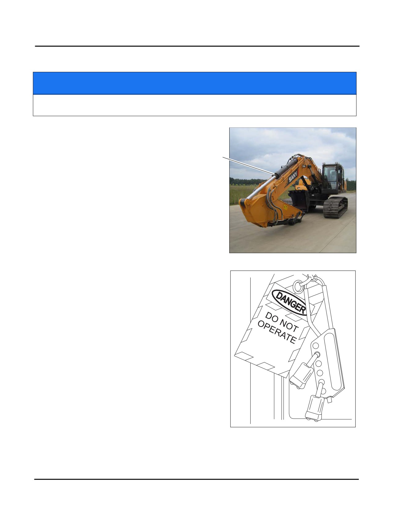
1. Park the machine on a level flat surface (a), shut the
engine down and remove the ignition key.
a
Fig. 5-4
2. Follow the Lock-out Tag-out procedure in the Safety
section of this manual. Always allow the systems time to
cool down before proceeding with any service. See
“Lockout/Tagout Procedures” on page 2-21 for details.
3. With the machine secured, proceed with the following:
NOTE: Obtain the maintenance record for this machine
and complete it at the close of all maintenance
procedures.
Checks:
•
Safety, Operation & Maintenance Manual
(see
page 5-15)
•
Operating Functions (see page 5-15)
•
Signal, Running Lights and Horn (see page 5-15)
•
Brakes (see page 5-18)
Fig. 5-5
•
Fire Extinguisher and First Aid Kit (see page 5-18)
•
Engine Oil Level (see page 5-19)
5-14
SY335 Excavator
Daily Maintenance
•
Pump Mounting Bolts (see page 5-20)
•
Fuel Level (see page 5-21)
•
Engine Coolant Level (see page 5-21)
•
Engine Serpentine Belt (see page 5-22)
•
Slewing Gearbox (see page 5-24)
•
Hydraulic Oil Level (see page 5-25)
•
Hydraulic Line Connections (see page 5-26)
•
Electrical System (see page 5-28)
•
Air Conditioner (see page 5-30)
•
Idler Wheel (see page 5-33)
•
Sheet Metal (see page 5-34)
Drain:
•
Primary Fuel Filter (see page 5-35)
Check
Safety, Operation & Maintenance Manual
Be sure the Safety, Operation & Maintenance manual is with the machine in the cab.
NOTE: If damaged or missing, contact your Sany distributor.
Operating Functions
WARNING
Ensure that no one is on or around the machine when testing operating functions. Failure to
ensure this could result in serious injury or possible death.
Check that all functions in the operating cab work correctly.
NOTE: See “Cab Interior” on page 3-5.
Signal, Running Lights and Horn
Check all lighting systems, be sure all lights function properly and are not damaged. Check the function of the
horn, be sure it is operational.
5-15
Daily Maintenance
SY335 Excavator
NOTE: See “Cab Interior” on page 3-5.
NOTE: If any component is damaged or inoperable, contact your Sany distributor.
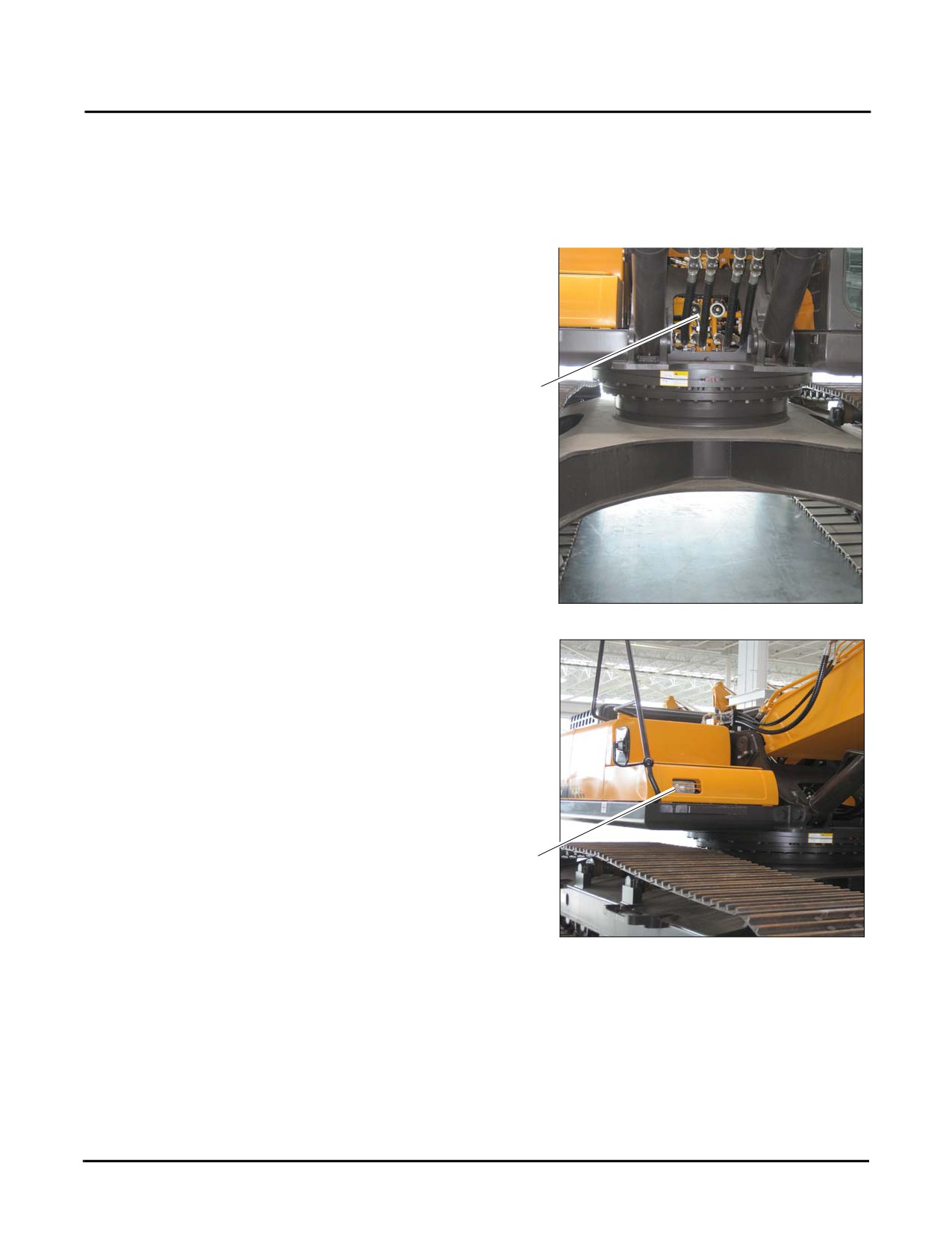
Ensure that the following lamps and other devices work properly:
•
Horns (1)
1
Fig. 5-6
•
Chassis work lamp (2)
2
Fig. 5-7
5-16
SY335 Excavator
Daily Maintenance
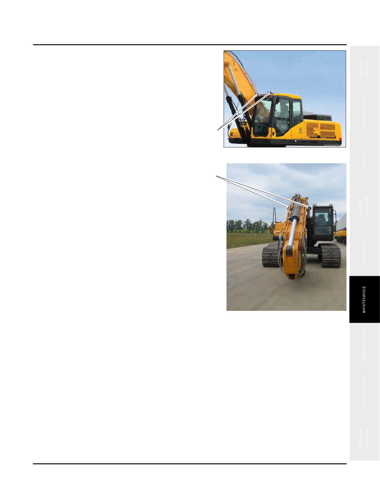
•
Cab work lamps (3)
3
Fig. 5-8
•
Boom work lamps (4)
4
Fig. 5-9
5-17