SANY Excavator SY335 (Part Number: 11282013). Safety, Operation & Maintenance Manual - page 4
Operation
SY335 Excavator
Before Travel
4-35
Right Turn
4-38
Left Turn
4-38
Straight Travel
4-38
Counter Rotate
4-39
Slopes
4-39
Operations in Water
4-40
Release Excavator from Mud
4-40
Recommended Applications
4-42
Backhoe operation
4-42
Digging a trench
4-42
Bucket Replacement
4-43
End of Workday Checks
4-45
Control Work Equipment
4-46
Set SAE/BHL Selector Switch
4-46
SAE Control Pattern
4-48
Swing
4-48
Arm
4-48
Boom
4-48
Bucket
4-49
BHL Control Pattern
4-49
Swing
4-49
Arm
4-50
Boom
4-50
Bucket
4-50
Park And Store The machine
4-51
Overnight Storage
4-51
Long Term Storage
4-52
Preparation
4-53
During Storage
4-56
Return to Service
4-56
Transport
4-57
Load the machine
4-57
Unload the machine
4-61
WARNING
Read and understand all safety precautions
and instructions in this manual before
reading any other manuals provided with this
equipment and before operating or servicing
it. Failure to do this can cause property
damage, personal injury or death.
4-2
SY335 Excavator
Work Area
WORK AREA
The work area is defined as the location where the work is being performed with the machine. The work area and
its surroundings include obstacles in the work and traveling areas, and the ground’s load-bearing capacity.
WARNING
Do not move the machine onto a surface or area that has not been approved for the machine.
The machine is heavy and could possibly break through surfaces that are not strong enough
to support the machine. This could cause damage to the machine as well as injury or possibly
death.
Remember the following points:
•
Those within the work area must wear personal protective equipment.
NOTE: See “Personal Protective Equipment” on page 2-11
•
The safety of all personnel within the work area is the responsibility of the machine operator.
General Job Safety
Review each of these carefully:
•
Only trained and authorized personnel shall be allowed to operate and service the equipment.
•
Keep this manual with your machine at all times for ease of reference and study it to become familiar with
all controls and safety decals before operating this equipment.
•
It is the responsibility of the owner and / or the operator to replace any safety, warning or caution decals if
they are defaced or removed from the equipment.
•
Never operate equipment that is unsafe or in poor operating condition.
•
Always perform a pre-operational check on your equipment before operating it. Never operate a machine
that is in need of repair, damaged or unsafe.
•
Never use your equipment for tasks it was not designed for; damage to the machine or injury to the
operator and other personnel may result.
•
Do not use swinging force to compact the ground or break objects.
•
Do not cut the bucket into the ground and use the traveling force to excavate.
•
Do not operate any cylinder at the very end of the stroke.
•
Do not use the bucket landing force for excavating, digging, breaking, or pile-driving.
4-3
Work Area
SY335 Excavator
•
Do not use the weight of the machine to excavate hard or rocky ground.
•
Move gradually, do not move any control lever or pedal to abruptly change the direction of the
machine.
•
Do not stop the machine suddenly by releasing the lever or pedal while traveling at high speed.
•
Never leave your equipment running and unattended. Instead, always park the equipment in a stable level
area, lower any work equipment to a safe position, lock the controls to secure the machine prevent
tampering by unauthorized personnel and turn the engine off before exiting the work site even for a
moment.
•
When leaving the job site, always lower all work equipment to a safe position and secure it properly to
avoid tampering by unauthorized personnel.
•
Before starting any work operations, travel or maintenance and repair procedures, be sure all personnel are
at a safe distance away from any point on the machine. Never allow anyone to stand near the machine
while in operation or under maintenance or repair. Remember, the larger the equipment, the more restricted
your visibility will be.
•
If pedestrians are in the area, proceed slowly and sound your horn. Keep in mind, pedestrians have the
right of way; a loaded or smaller machine has the right away over a larger or unloaded machine.
•
Always study the job site carefully.
•
The operator of this equipment must be alert, physically fit and free from the influences of alcohol, drugs
or medications that might affect eyesight, hearing, reaction or judgment.
•
Follow all rules relating to safety as outlined in this manual and by your company. Never get involved in
horseplay.
•
Know your location to report an accident or fire. In case of an emergency, have a local emergency phone
number available.
•
Keep all safety equipment and job-related warning equipment in good working condition. Replace them if
they should become damaged.
•
Never drive up to anyone standing in your path of travel. Always be sure all personnel are standing to the
side when you approach them and they acknowledge your approach.
•
When working with another person on a work site, insure all personnel involved understand all hand
signals that are to be used.
•
The operator shall respond to operating signals from the proper signal person only but shall obey a stop
signal at any time from anybody.
•
Take action to prevent unauthorized personnel from entering or approaching the job site area.
•
As an operator, you must always be able to see the point of work location. If this is not possible then a
spotter must be used. If visibility should become blocked for any reason, stop operation immediately.
4-4
SY335 Excavator
Work Area
Job Site Safety
Within the job site is the “work area” (where the actual job function is being performed). Within the work area are
“hazard areas”, that is, areas immediately surrounding the machine where personnel may be at risk due to machine
operation or movement.
With the machine operator being responsible for the safe and correct operation of the machine, he/she is
responsible for safety within the hazard zones while the machine is in use. Immediate work stoppage and machine
shutdown by the machine operator is required if unauthorized personnel enter any of the hazard areas.
•
All hazard areas must be clearly identified, marked and secured to prevent access by unauthorized
personnel and must be visible to the machine operator at all times and under all circumstances. If this is not
possible, a signal person must be assigned to supervise activities within hazard areas. Personnel within a
hazard area must use increased caution and wear suitable personal protective equipment as required.
4-5
Work Crew
SY335 Excavator
WORK CREW
Supervisor
This person is the legal representative of the equipment owner and has overall responsibility for the safe and proper
use of the machine. They are required to be at the machine during inspection, preparation for operations and post-
work procedures.
Besides the machine, the supervisor also has overall responsibility for personnel and safety matters. This means
they must ensure that:
•
Only qualified or properly instructed persons work on or with the machine.
•
Written safety, operational and other instructions are always available and have been read and understood
by the work crew.
In addition, the supervisor is responsible for producing operating procedures unique to the job at hand and which
may not be included in this technical publication but are of national import.
These procedures must cover the duties involved in supervising and notifying special organizational features, e.g.,
organization of work, working procedures or the personnel entrusted with the work.
Also, there must be reference to other general valid legal and also required regulations regarding accident
prevention and environmental protection. These may also include how to handle hazardous substances (for
instance, Material Safety Data Sheets), distribution and proper wearing of personal protective equipment or with
national road traffic regulations.
Familiarize yourself with the job site and learn how to operate fire extinguishers. Observe the fire alarm and fire
fighting procedures.
Finally, the supervisor must be aware of and follow regulations as issued by legal authorities in the job site county,
national supervisory bodies, and the responsible commercial liability insurance company.
Owner and Other Authorized Personnel
Only those personnel who have read and understand the instructions in the Safety section of this manual can be
allowed to operate and maintain this machine. All operating and maintenance personnel must be periodically tested
on machine and safety knowledge to maintain their qualifications to use the machine.
Operations must cease if any safety defect is found and any accident, especially those concerning serious injury
and/or property damage, must be reported to .
The machine must be maintained and repaired in accordance with maintenance intervals indicated in this manual.
Inspections mandated by the manufacturers must be performed as outlined in this manual in addition to other
inspections mandated by relevant national and local regulations.
4-6
SY335 Excavator
Work Crew
Machine Operator
This individual is trained in and responsible for the safe and correct operation of the machine. He/she reports
directly to the supervisor.
The machine operator must do the following:
•
Reject the work site if they have doubts regarding technical safety.
•
Become familiar with the working area and surroundings before work is begun.
The machine can only be operated by:
•
An operator who is physically capable, has passed the exam and holds a valid certificate
•
A trainee who has been instructed for over half a year under the direct supervision of a qualified operator
•
Maintenance and operating personnel needing to operate the machine for their tasks
•
Safety supervisor entrusted by the superior
•
Only these persons listed above are allowed to enter the cab
WARNING
The machine must not be operated by persons under the influence of alcohol, drugs or
medication!
The operator must become familiar with the following:
•
(Prior to first-time operation) Read and completely understand the instructions in this Operator Manual.
•
Read and completely understand the load capacity for this machine.
•
Know and obey the operating procedures, relevant laws and regulations.
•
Know and follow the requirements for safe operation.
•
Know and use the required safety precautions and protective devices.
•
Know basic information about the systems of this machine.
•
Know and use the correct hand signals between the machine operator and a signal person.
4-7
Work Crew
SY335 Excavator
Obligations and precautions of the machine operator:
•
Before starting to work, the machine operator must check brake functions and the emergency stop devices.
He/she must monitor the condition of the machine for obvious defects.
•
The operator must concentrate solely on machine operation when using the machine.
•
Stop machine operations in case any defects endangering safety are found.
•
The machine operator must control, operate and adjust the machine to protect the personnel or other
facilities in the vicinity of the machine.
The machine operator must make sure that:
•
All control devices are set to neutral or idle position before supplying power to the drive components.
•
The control devices are set to neutral or idle position and the power supply is shut off before leaving the
control platform.
•
The machine operator must give warning signs when necessary.
•
He/she uses all necessary personal protective equipment on the job.
4-8
SY335 Excavator
New Machine Run-In
NEW MACHINE RUN-IN
Your machine has been thoroughly adjusted and tested
before shipment. However, initial operation of the machine
under severe conditions can adversely affect the
performance of the machine or shorten the machine life.
Therefore, Sany recommends that you allow a run-in period
of 100 operating hours for a new machine.
Properly running-in a new machine is crucial for
guaranteeing a long service life of the machine by allowing
time for new cylinder piston rings and other internal engine
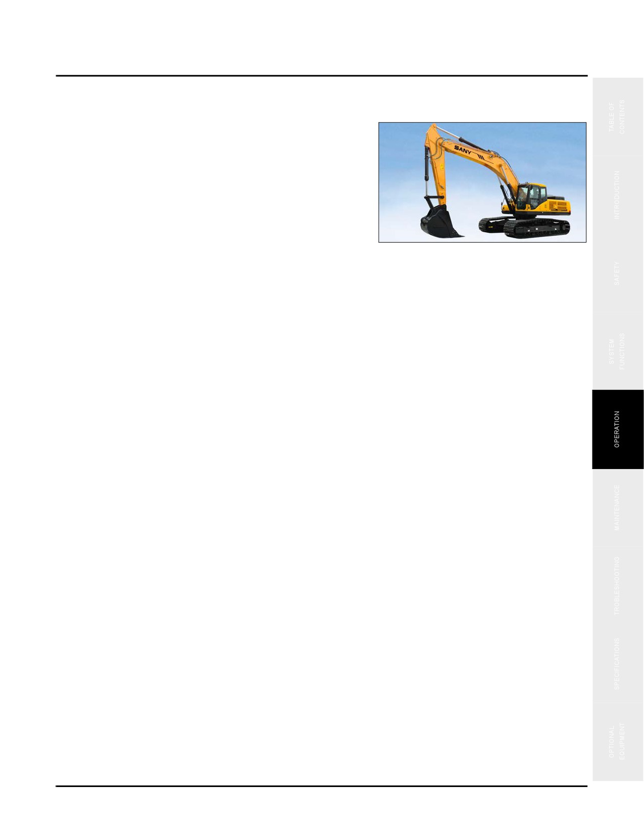
Fig. 4-1
parts to wear in properly. Ensure that the machine is in a
normal working condition before proceeding with the
running-in.
Refer to the applicable engine manual for details on running-in the engine.
The following points are not limitations but instead guidelines for familiarization of the machine and development
of good operating habits.
•
Operate as much as possible in the half to three-quarters throttle or load range.
•
When performing an engine cold start, keep the engine speed at or near idle until the engine reaches its
normal operating temperature.
•
Avoid long periods of operation with the engine at idle or continuous maximum horsepower levels.
•
Avoid sudden starts, movements or stops.
•
Manage engine power to a point that allows acceleration to governed speed when conditions require more
power.
•
Monitor the instruments frequently — especially the engine oil and coolant pressures. Shut down the
machine at the first indication of an abnormal reading.
•
Shift down to a lower speed setting before climbing up a slope to keep the engine speed elevated.
•
Check all components frequently for proper operation, unusual noises, and excessive heating.
•
Frequently check all machine operating temperatures. Determine the cause if overheating occurs and
perform adjustments or repairs immediately.
•
Always let the system cool down at the end of the working day.
•
Frequently check the bolts and screws for tightness.
•
After running-in has been completed, have the machine chassis maintenance procedures performed at an
authorized Sany service center.
4-9
Mount and Dismount the Machine
SY335 Excavator
MOUNT AND DISMOUNT THE MACHINE
Mounting or dismounting could pose some hazards.
Observe the following:
•
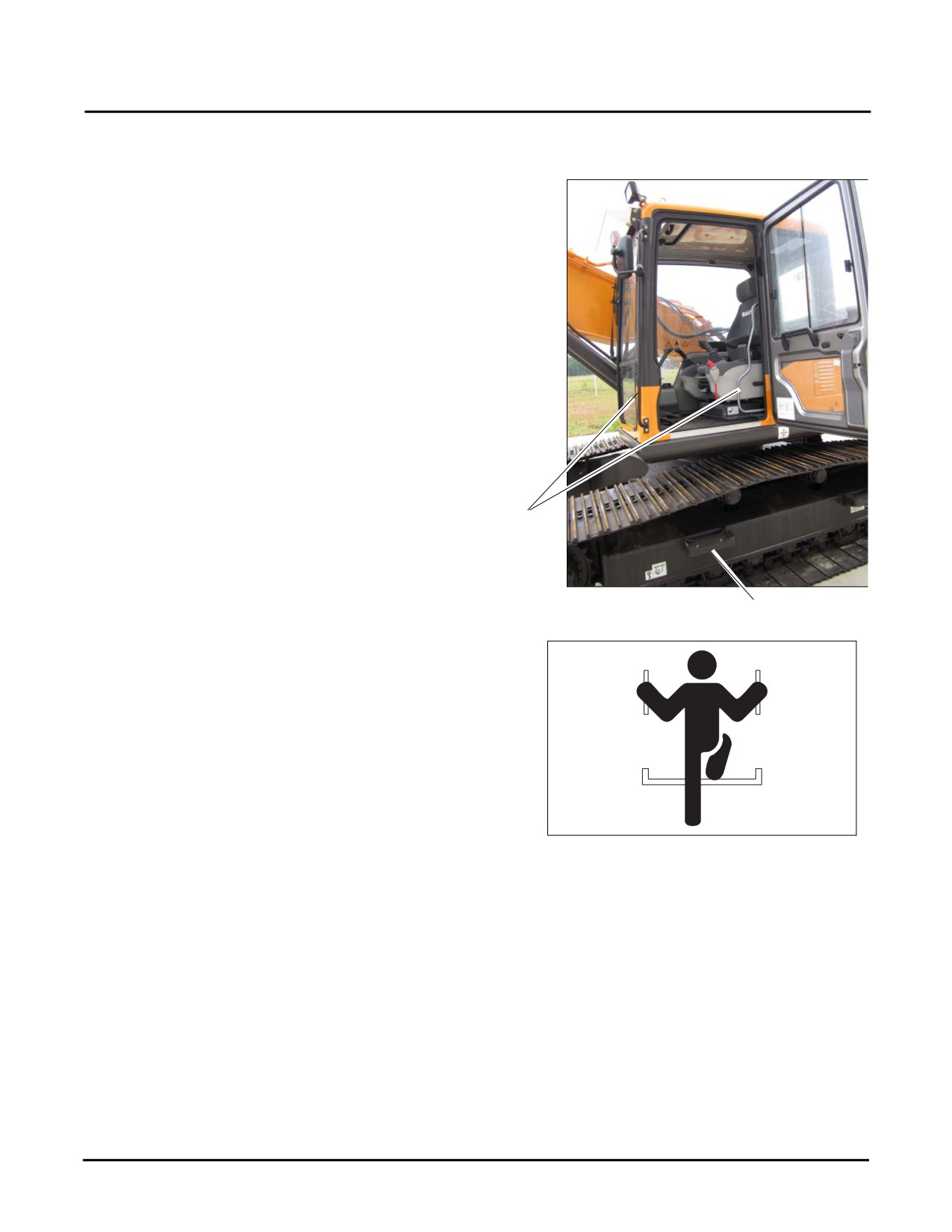
Always be sure the machine is at a full stop before
attempting to access the machine. Never jump onto
or off of the machine.
•
Never exit or enter the machine cab or deck by any
other means than the access systems provided steps
(a) and grab handles (b).
a
b
Typical
Fig. 4-2
a
•
Always maintain a three-point contact (both feet
and one hand or one foot and both hands) with the
handrails, steps, catwalks and platforms to ensure
that you support yourself properly.
•
If you will be walking on the carrier surface of the
machine, always try to maintain a three-point
contact whenever possible to help keep your
balance.
•
Do not walk on a surface of the machine if slip-
Fig. 4-3
resistant material is missing or excessively worn.
Do not step on surfaces of the machine that are not
approved or suitable for walking and working. Keep all walking and working surfaces of the machine
clean, dry and slip-resistant.
•
Wear shoes with a highly slip-resistant sole material. Clean any mud or debris from shoes before entering
the machine cab or climbing onto the machine superstructure.
•
Always keep handrails, step plates and walkway areas clean and clear of mud, oil, grease or similar debris.
If these areas are damaged, have them repaired or replaced immediately.
•
Never leave tools or similar objects on the machine catwalks or service areas. These could fall and get
caught in the machine operating systems.
4-10
SY335 Excavator
Mount and Dismount the Machine
•
Never climb on areas of the machine that are not
designated walk areas. You could lose your balance,
slip and fall from the machine.
•
Never climb on or off the machine with tools or
similar objects in your hands.
•
Do not modify the machine’s access system in any
way that has not been evaluated and approved by
.
Fig. 4-4
4-11
Pre-Start Checks
SY335 Excavator
PRE-START CHECKS
CAUTION
Failure to perform this inspection and have needed issues resolved may result in further
damage to the machine or possible injury to the operator and other personnel.
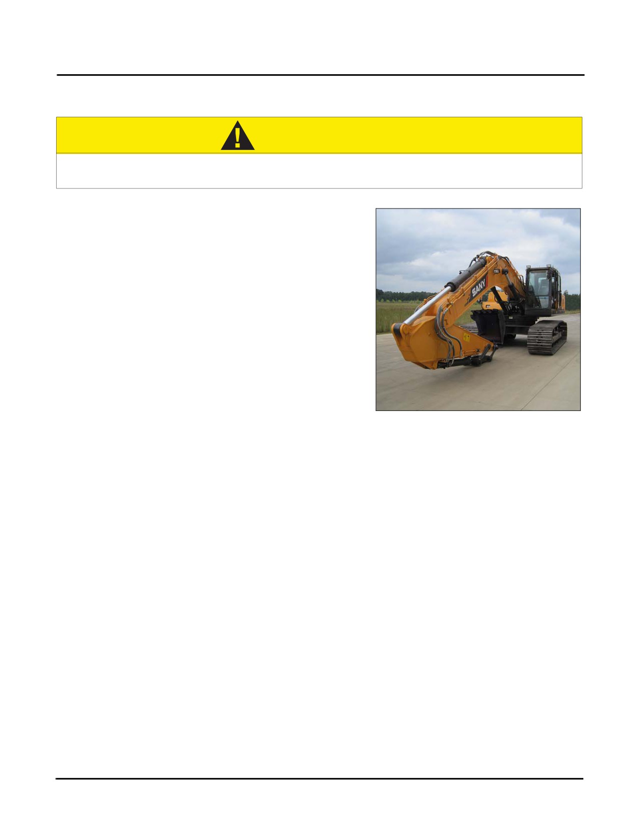
Always complete a walk-around visual inspection of the
machine with special attention to structural damage, loose
equipment, leaks or other conditions that require immediate
correction for safe operation.
•
Check work equipment, cylinders, arms, and hoses
for cracks, excessive wear or loosening.
•
Remove any dirt or debris around the engine,
battery and tracks.
•
Check for any coolant or oil leaks around the
engine.
•
Check the hydraulic pump, hydraulic tank, hoses,
and joints for any sign of leaks.
Fig. 4-5
•
Check the undercarriage (track, sprockets, tension
rollers, and guards) for damage, wear, loose bolts,
or roller leakage.
•
Check the handholds and step for any looseness or damage.
•
Check the hoisting hook, guide plate and hook seat on the back of the bucket for any damage if
installed.
NOTE: If any problems are found during your pre-start check, have these problems resolved immediately.
Never operate a machine that is unsafe, damaged or in need of repair.
Daily Maintenance Record
Ensure that the Daily Maintenance Checks have been performed before operating this equipment.
4-12
SY335 Excavator
Pre-Start Checks
Fuel Level
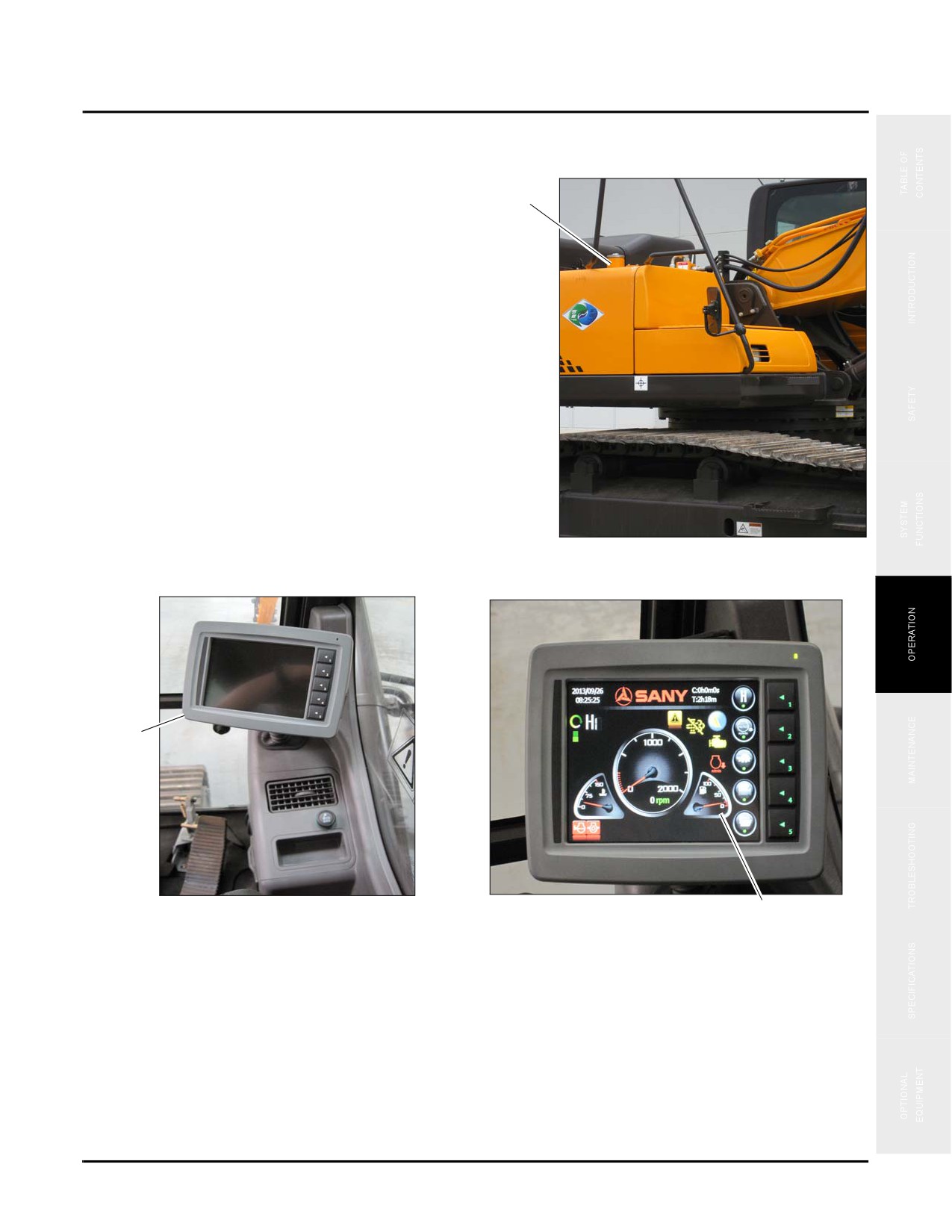
To check the fuel level first make sure the fuel cap (a) is on
tight and locked.
a
Fig. 4-6
The system monitor (b) in the cab displays the fuel level
indicator (c).
b
Fig. 4-7
c
NOTE: See “Refueling” on page 2-25 if fuel level is low. Use the following fuel grades:
•-30# Diesel: -22° to 68° F (-30° to 20° C)
•-10# Diesel: 14° to 122° F (-10° to 50° C)
•0# Diesel: 32° to 122° F (0° to 50° C)
4-13
Pre-Start Checks
SY335 Excavator
Draining Primary Fuel Filter
CAUTION
Never smoke or service the fuel system near open burning locations. Doing so could result in
fire, explosion or possible injury.
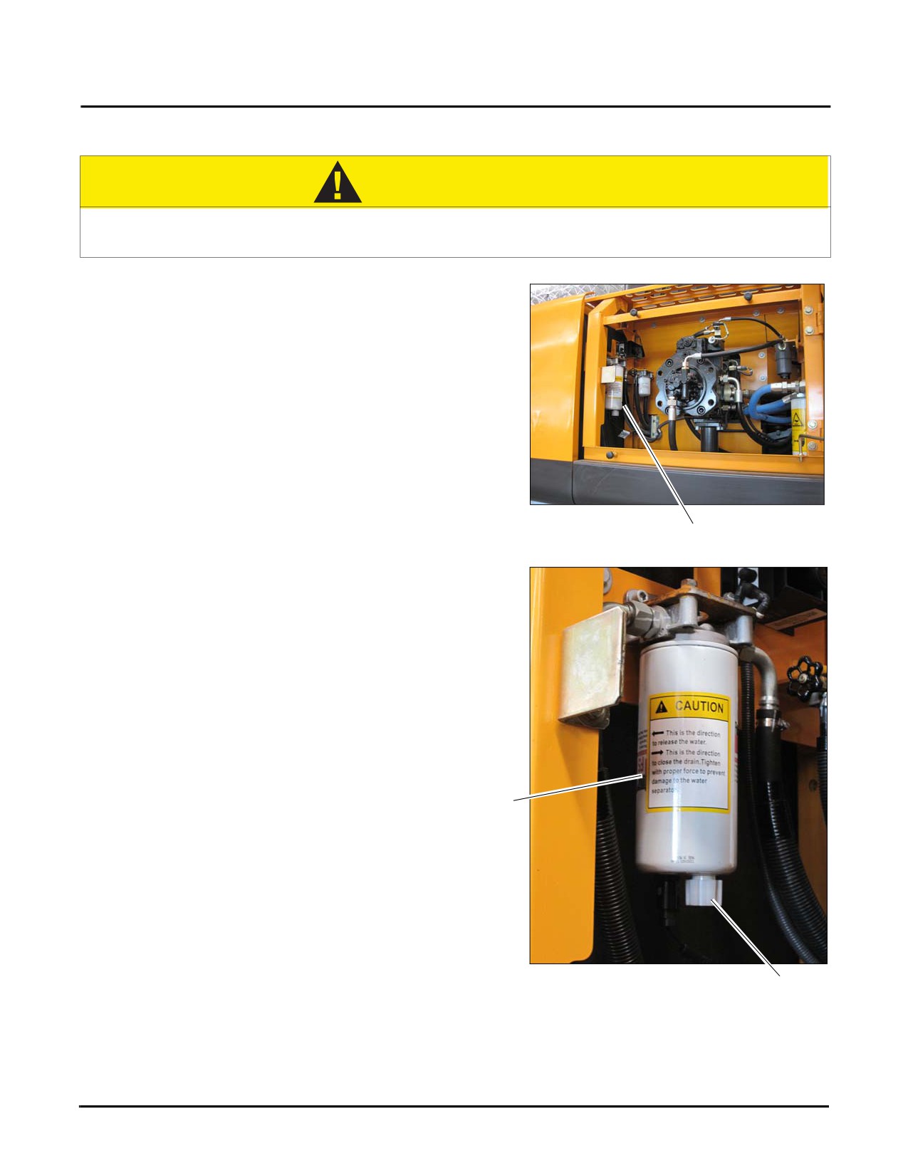
1. Locate the primary fuel/water separator (a) within the
hydraulic pump enclosure behind the door on the right
side.
Fig. 4-8
a
2. Place an appropriate size container below the primary
fuel/water separator (a), then open the drain valve (b) to
allow all water or contaminated fuel to drain from the
filter.
NOTE: Avoid draining the primary fuel/water
separator completely, air could enter the fuel
system.
3. Close the drain valve (b) when the flow from the
primary fuel/water separator is free of water and
a
contamination, and dispose of the contaminated fuel
properly.
NOTE: See “Environmental Precautions” on page 2-
29
Fig. 4-9
b
4-14
SY335 Excavator
Pre-Start Checks
Hydraulic Oil Level
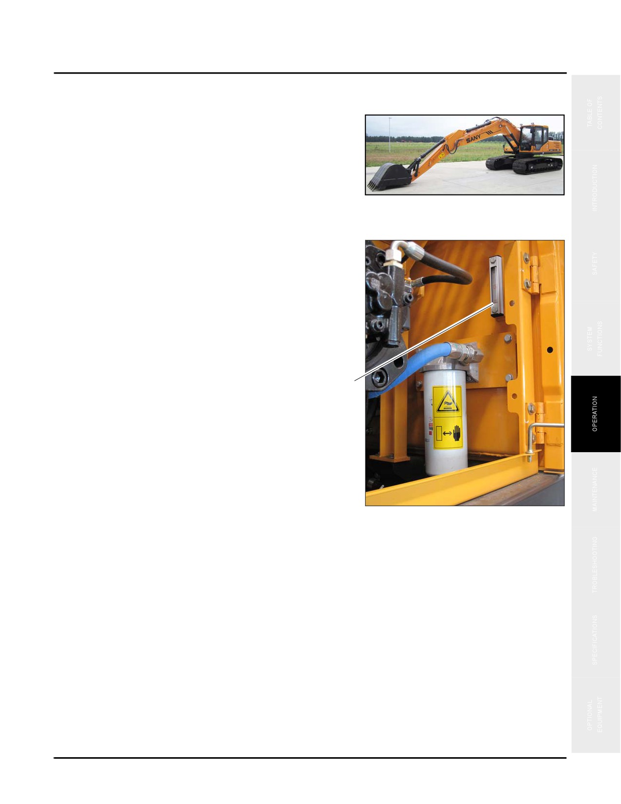
The work equipment should be positioned as shown in the
illustration. If the equipment is NOT in the illustrated
position, start the engine and, running the engine at low
speed, retract the arm and bucket cylinders, lower the boom
front end to rest on the ground, and stop the engine and
follow normal shutdown and parking procedures.
Typical
NOTE: See “Control Work Equipment” on page 4-46
Fig. 4-10
1. Locate the hydraulic oil level sight glass (a) within the
hydraulic pump enclosure behind the door on the right
side.
a
Fig. 4-11
4-15
Pre-Start Checks
SY335 Excavator
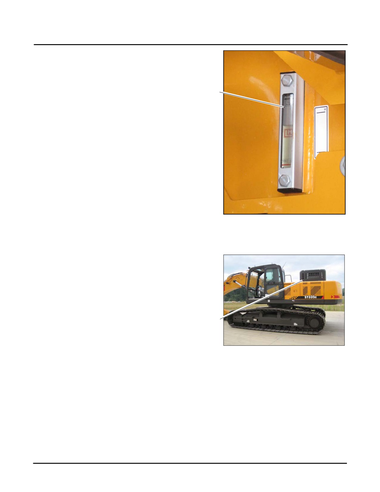
2. Check the hydraulic oil tank level.
NOTE: The oil level should be between the H and L
marks on the site glass (b). If the level is not
within the specified level fill the system with
b
hydraulic fluid (HDZ32 or HDZ46)
•HDZ32: -15° to 86° F (-25° to 30° C)
•HDZ46: -4° to 104° F (-20° to 40° C)
Fig. 4-12
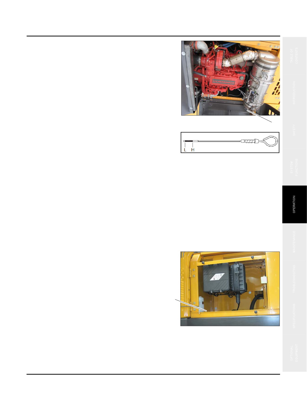
Engine Oil Level
1. Open the engine hood (a).
a
Fig. 4-13
4-16
SY335 Excavator
Pre-Start Checks
2. Pull out the engine oil dipstick (b) and wipe off the oil
with a clean lint free cloth.
3. Insert the dipstick to the bottom and pull it out again.
Fig. 4-14
b
NOTE: The oil level should be between the H and L
marks on the dipstick. If the oil is not within
the specified level, fill the engine with engine
oil (until the oil level is between the H and L
Fig. 4-15
marks). Please use one of the following oil
types based upon the operating temperature of
your work area.
•5W- 30: -22° to 86° F (-30° to 30° C)
•5W- 40: -22° to 104° F (-30° to 40° C)
•10W- 30: -4° to 104°F (-20° to 40° C)
•15W- 40: -8° to 104° F (-15° to 40° C)
•40W: 32° to 104° F (0° to 40° C)
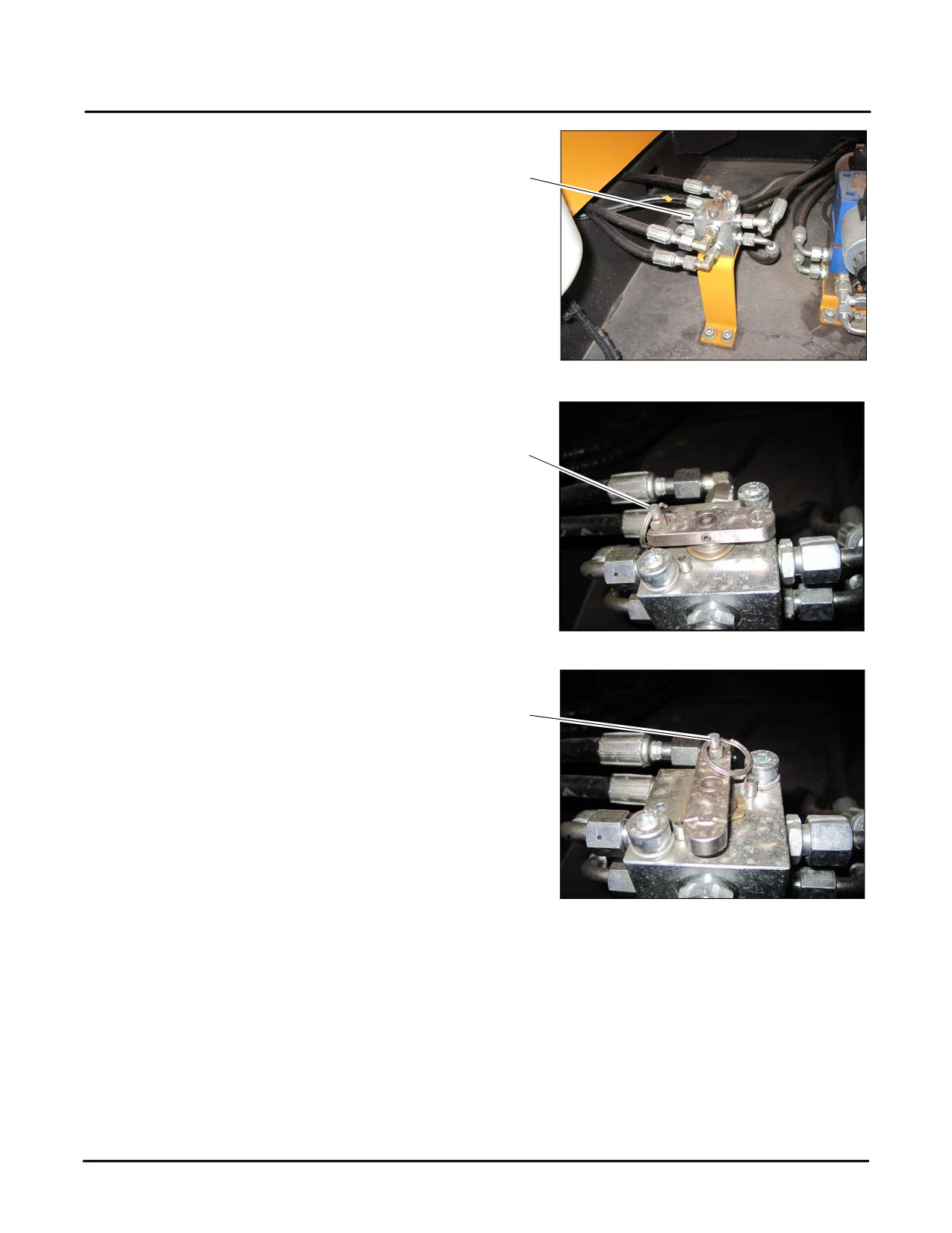
SAE/BHL Selector Switch
The SAE/BHL selector switch (a) is located below the
engine air cleaner inside the left side front cover.
a
Fig. 4-16
4-17
Pre-Start Checks
SY335 Excavator
The SAE/BHL selector switch (b) swaps the control of the
boom and the arm from one joystick to the other. To go to
SAE position see step 2, to go to BHL position go to step 1.
b
Fig. 4-17
1. Pull the pin up (c) and rotate the bar to the left for BHL.
Release the pin to lock the bar in place
BHL
c
Fig. 4-18
2. Pull the pin up (c) and rotate the bar to the right for
SAE. Release the pin to lock the bar in place
SAE
c
NOTE: See “SAE Control Pattern” on page 4-48 and
See “BHL Control Pattern” on page 4-49 for
more information.
Fig. 4-19
4-18
SY335 Excavator
Pre-Start Checks
Engine Coolant Level
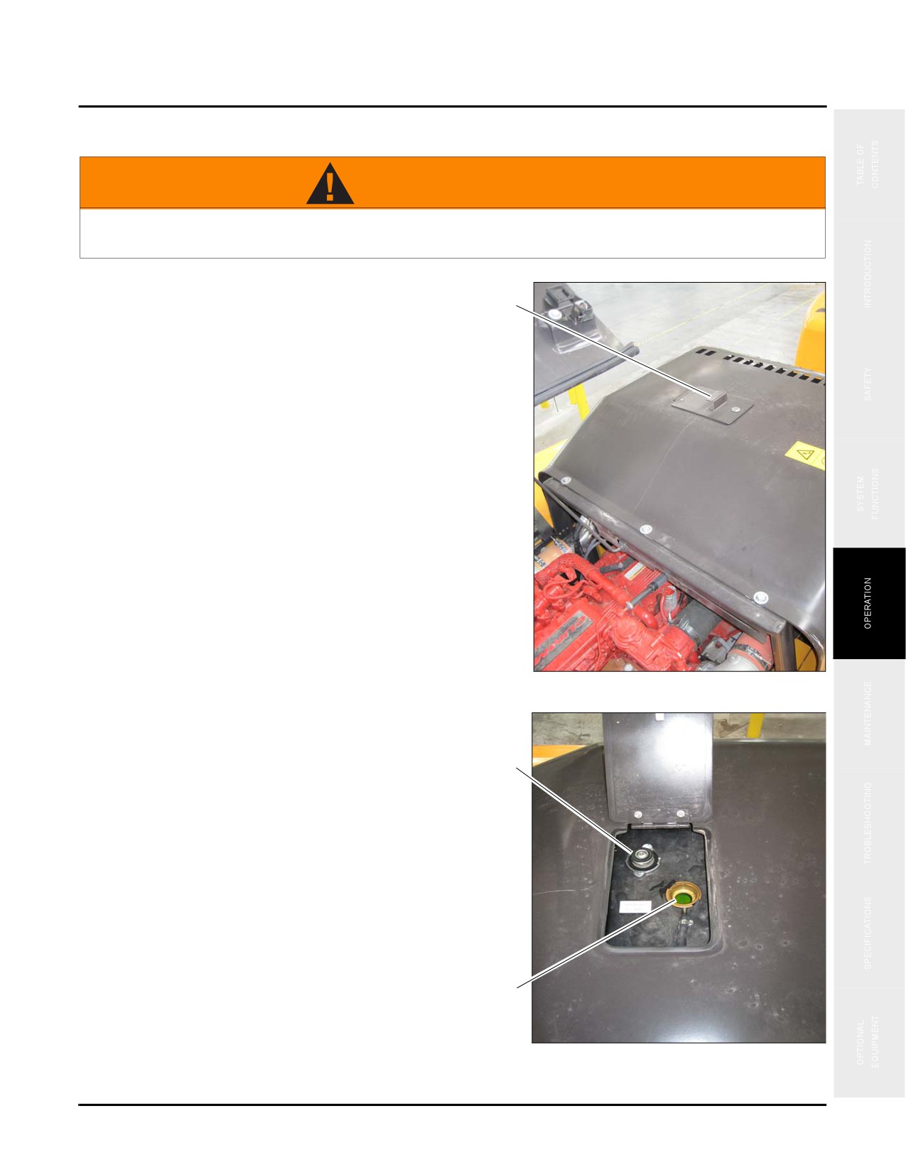
WARNING
Check coolant level only when the engine is cold and there is no pressure in the system.
Failure to follow this directive may cause severe burns or other injuries.
1. Locate and open the Radiator Access Door (a) next to
the engine compartment.
a
Fig. 4-20
2. Check and make sure the radiator cap is cool to the
touch; then open the radiator cap (b) and visually check
to ensure that there is coolant in the radiator.
b
NOTE: Loosen the cap of the radiator slowly to
release internal pressures within the coolant
system.
3. Add coolant as necessary to a level that shows the
coolant in the bottom of the radiator neck (c).
NOTE: Use any coolant that meets the standards
outlined by American Society for Testing
and Materials
(ASTM) standard D6210.
Sany recommends use of Fleetguard Charge
c
D6210 coolant adding Supplement Coolant
Additive (SCA) as mandated by your work
environment.
Fig. 4-21
4-19
Pre-Start Checks
SY335 Excavator
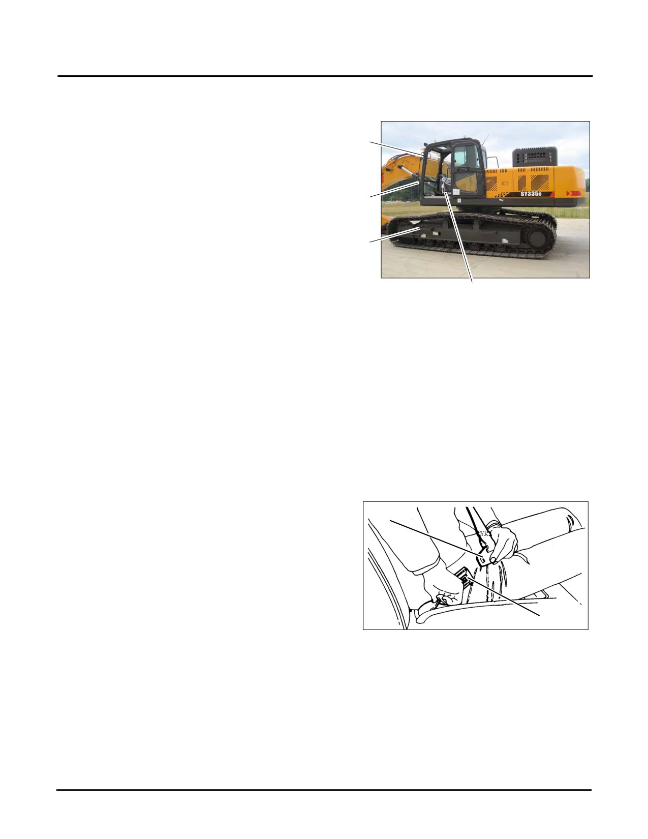
Cab
Clean these items after each shift:
a
•
Windows (a) and mirrors
NOTE: Remove all trash from inside the cab to avoid
its interfering with operation of the
b
equipment.
•
Handrails (b)
c
•
Steps (c)
NOTE: Wipe the handrails to remove grease or dirt to
Fig. 4-22
b
help ensure a firm grip is possible when
entering or exiting the cab area.
Safety, Operation and Maintenance
Manual
Ensure that the Safety, Operation and Maintenance Manual is in the cab.
Seat, Seat Belt, Mirrors and Backup
Camera
Seat and Seat Belt
1. Always adjust the driver’s seat to the position in which
you will drive before fastening the seat belt.
a
NOTE: See “Seat and Seat Belt” on page 3-6 for
additional information
2. Pull the belt across your lap and push the latch plate (a)
into the buckle (b) until it clicks.
b
3. To reduce the risk of sliding under the belt during a
collision, put the belt across your lap as low on your
Fig. 4-23
hips as possible and pull it towards the door to a snug fit
so the retractor can take up the slack.
NOTE: The lap/shoulder belt is designed to lock only during a sudden stop or impact. At other times it should
move freely.
4-20
SY335 Excavator
Pre-Start Checks
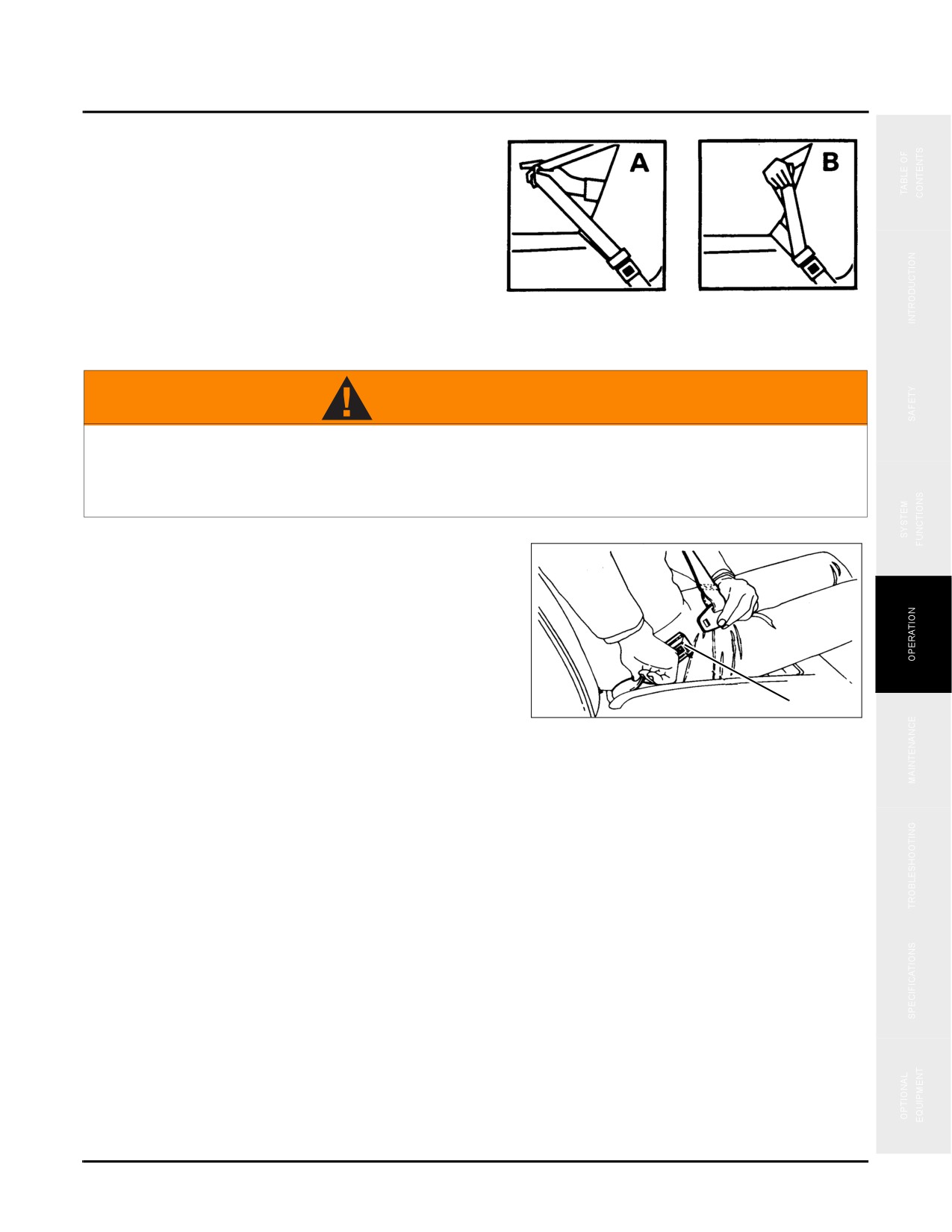
4. If the shoulder belt is too snug, do the following:
A. Pull the shoulder belt out at least 5 in. (13 cm) so
that when it is released, it returns to your chest.
B. Then pull down on the shoulder belt the least
amount needed to ease pressure but no more than
1.0 in. (25 mm) and release it.
Fig. 4-24
5. To reduce slack in the belt, pull the belt out as you did in
step 4A.
WARNING
Keep any shoulder belt slack to no more than 1 in. (25 mm). Belt slack beyond this amount
could significantly reduce your protection in an accident because the belt is too loose to
restrain you as intended. Failure to observe and follow this warning could result in personal
injury or death.
6. To unfasten the belt, press the button (b) in the center of
the buckle. To store the belt, pull it out about 7 in.
(18 cm) and release it.
The belt should retract when the buckle is unlatched. To
help prevent damage to the seat belt and interior, be sure the
belt is fully retracted and the latch plate is out of the way
before closing the door.
b
NOTE: Seat belt assemblies are maintenance-free;
Fig. 4-25
however, they should be periodically
inspected to ensure that they are not
damaged and are in proper operating
condition, especially if they have been
subjected to severe stress.
Mirrors
Adjust the side mirrors for clear vision and safe driving.
NOTE: See “Cab Exterior” on page 3-4 for additional
information.
4-21
Pre-Start Checks
SY335 Excavator
Backup Camera
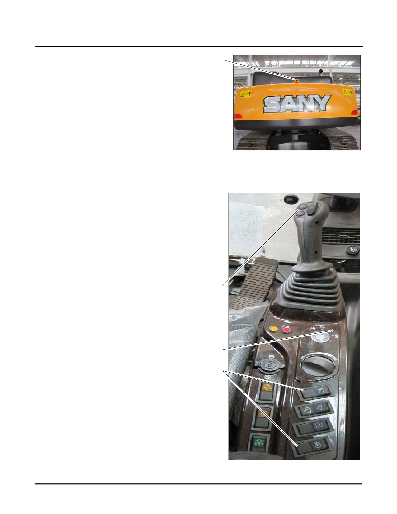
a
Ensure your rear view camera (a) is operating correctly and
is free of all obstructions.
NOTE: See “Combined Instrument Display screen”
on page 3-28 for additional information.
Fig. 4-26
Work Lights and Warning Devices
Check the following for proper operation with the key set
to the ON position (a).
•
Work Lamps (b)
•
Horn (c)
•
Travel alarm (sounds when travel pedal or lever is
moved)
c
a
b
Fig. 4-27
4-22
SY335 Excavator
Pre-Start Checks
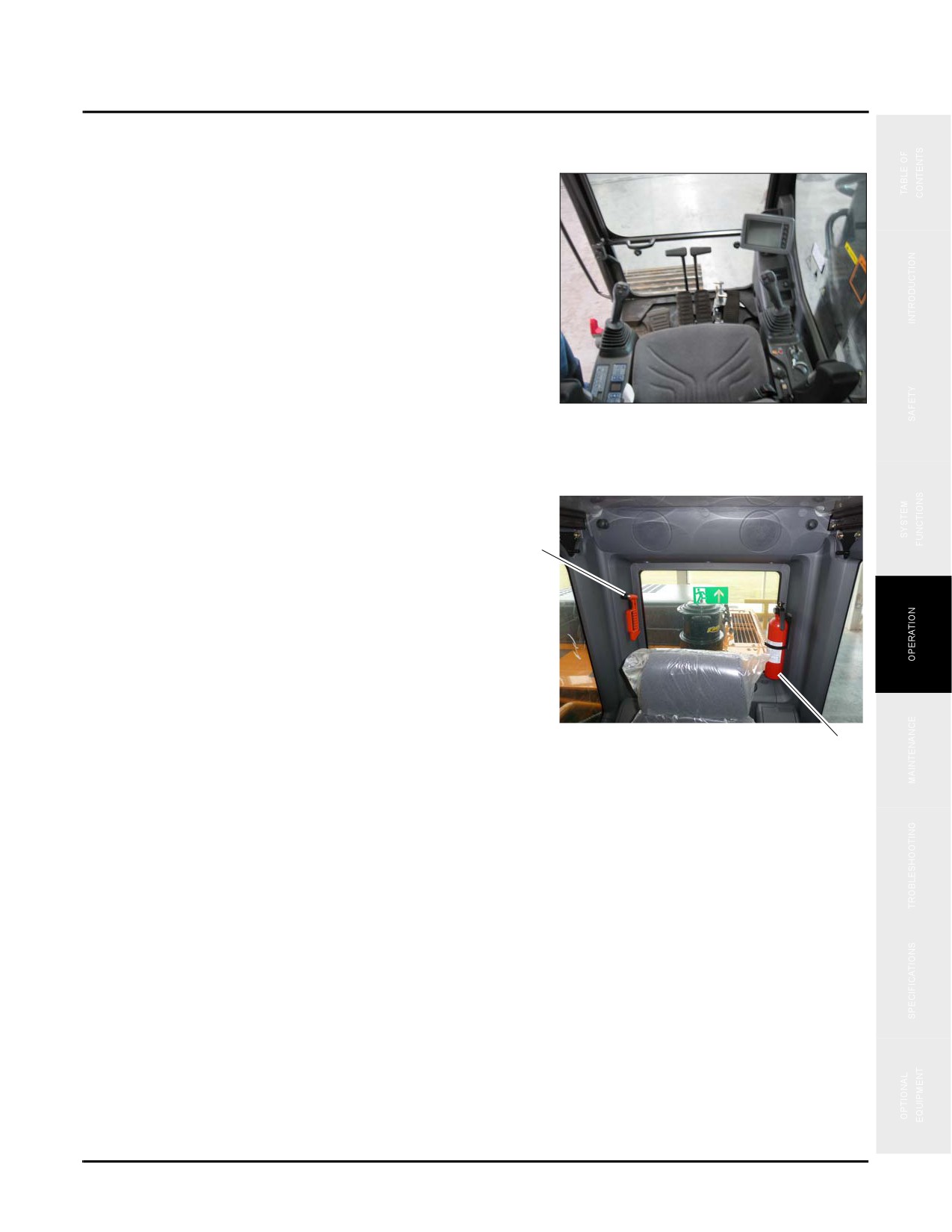
Operator Controls
Check all operator control lever movements for smooth
operation with key in the ON position. The control lever
should return to neutral freely. There should not be any
excessive play in the control lever.
NOTE: See “Cab Interior” on page 3-5 for controls
information.
Fig. 4-28
Fire Extinguisher & Escape Tool
Check that both the fire extinguisher (a) and the escape tool
(b) are on the back wall of the cab.
b
NOTE: Be sure the fire extinguisher is a minimum of
a 10 pound “A, B, C” fire-rated extinguisher
(ASME B30.5-2007).
NOTE: See “Extinguisher and First Aid Kit” on
page 2-14.
Typical
a
Fig. 4-29
4-23
Combined Instruments Display/Monitor Settings
SY335 Excavator
COMBINED INSTRUMENTS DISPLAY/MONITOR SETTINGS
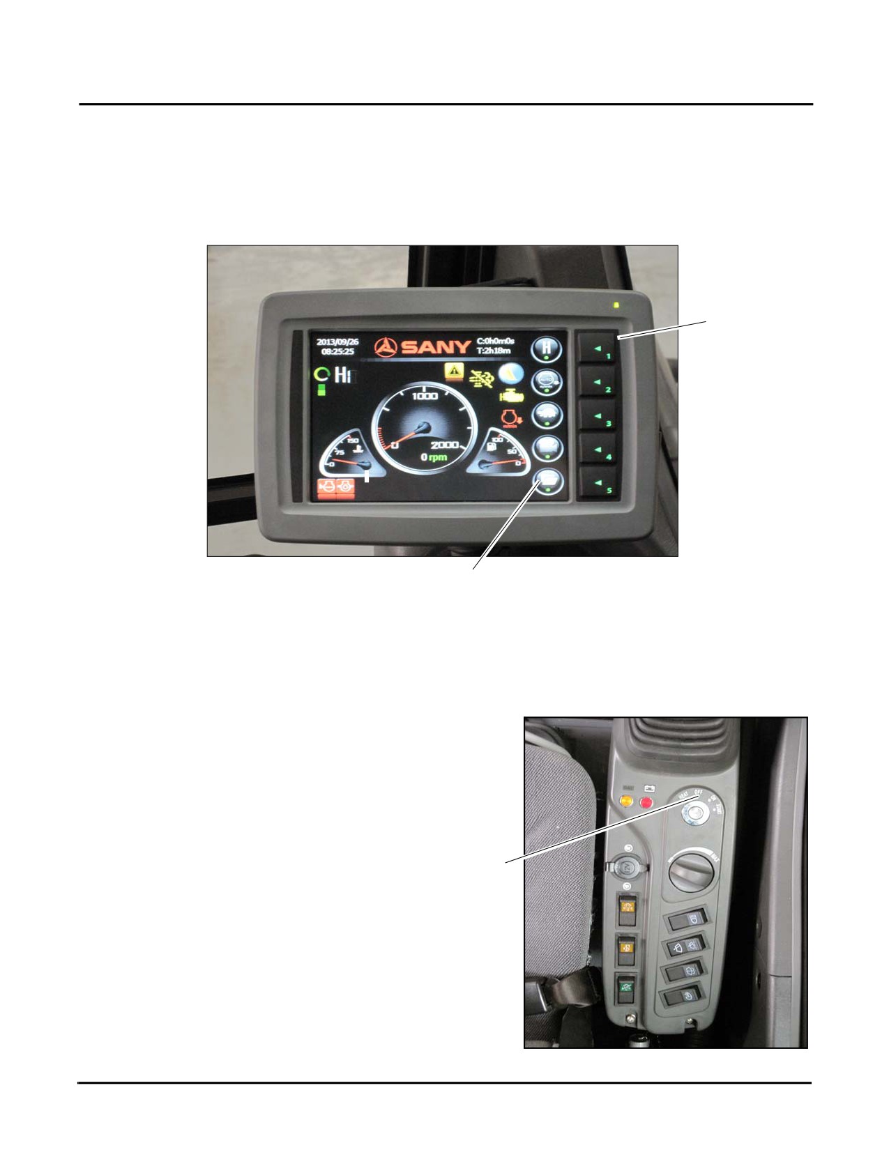
When the key switch of machine is turned to the ON position, the Combined Instrument Display is energized by
the engine battery and initializes. A full display of the working Combined Instrument Display is shown below:
2
Fig. 4-30
1
Additional details may be seen on the display by using the Function Icons (1) and the corresponding Function Keys
(2).
Set Language Display - First Time
1. Turn the ignition switch
(a) to the ON position to
display the Operator screen on the Combined
Instrument Display.
a
Fig. 4-31
4-24
SY335 Excavator
Combined Instruments Display/Monitor Settings
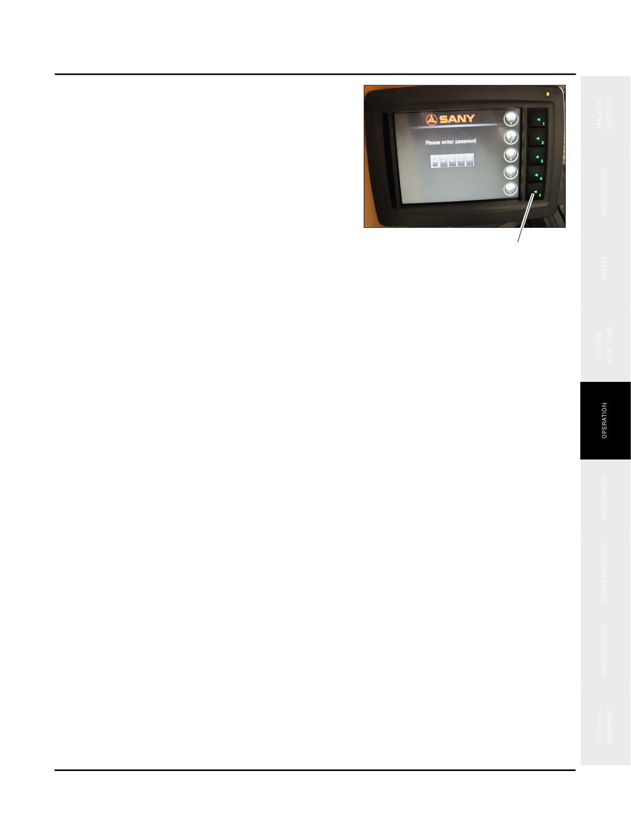
2. Press Key 5 to go to System Information/Password (b)
See “Function Keys” on page 3-28.
3. Enter your 5-digit password. Each digit is indicated by
an asterisk (*) standing for a value from 0 to 9. A
numeral appears at the digit where the cursor is located
while the other four digits remains as asterisks.
4. Pressing Key 2 switches between Left-Right function
and increase/decrease function.
5. Pressing Key 1 goes back to previous page.
Fig. 4-32
b
Use the function keys to:
•
Key 1: Back to previous page.
•
Key 2: Start or stop setting up the code number on digit where the cursor is located.
•
Key 3: Decrease a value or move the cursor to the left digit.
•
Key 4: Increase a value or move the cursor to the right digit.
•
Key 5: Check the validity of password entered. If it is valid, you have access to the Main Menu.
4-25
Combined Instruments Display/Monitor Settings
SY335 Excavator
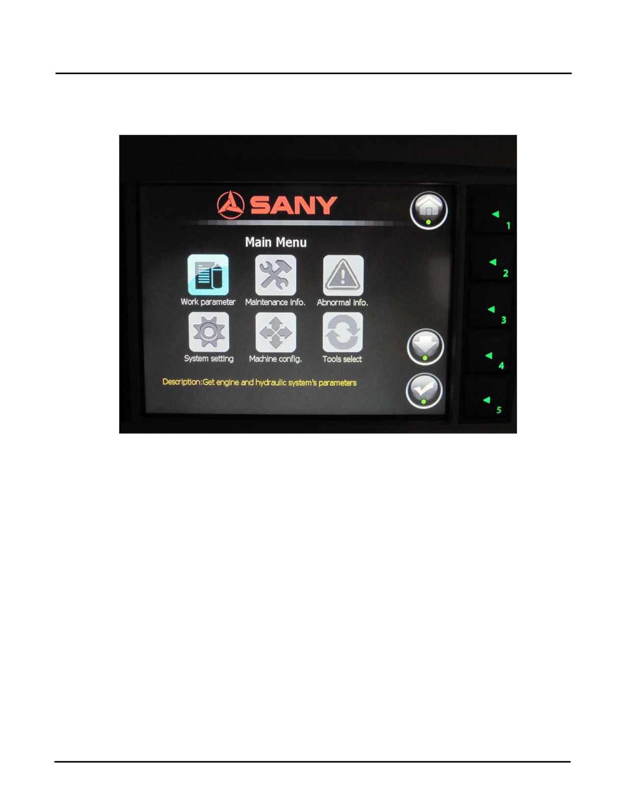
6. Once you enter the password you should go to the Main Menu. (See “Main Menu Functions” on page 3-30).
These are a list of system functions that can be accessed by selecting an item and then entering the
corresponding page. Each icon will be highlighted as you chose them.
Fig. 4-33
•Parameter - view the running parameters of the engine and hydraulic system
•Maintenance - view maintenance information on the machine
•Fault Info (Error codes)
•System Setup - language selection
•Machine Config - configure the machine and view configuration of the machine
•Tools Select (Bucket- Breaker - Nibbler)
4-26
SY335 Excavator
Combined Instruments Display/Monitor Settings
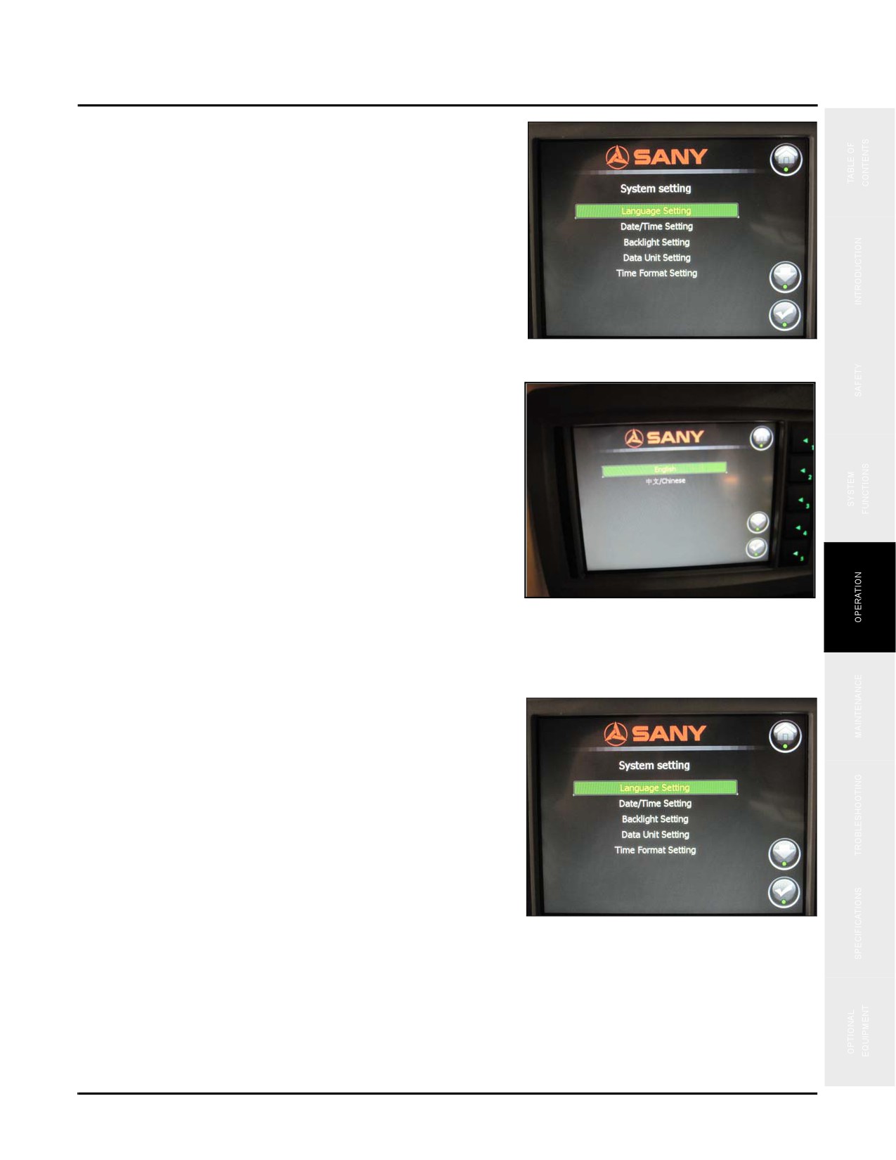
7. Go to System Settings for language selection
(See
“System Language Selection” on page 3-33).
8. Pressing Key 5 will take you to Language Setting.
Fig. 4-34
9. You will see a display of language options.
•
Press Key 3 to scroll up the list.
•
Press Key 4 to scroll down the list.
•
Press Key 5 to accept the language selected.
Fig. 4-35
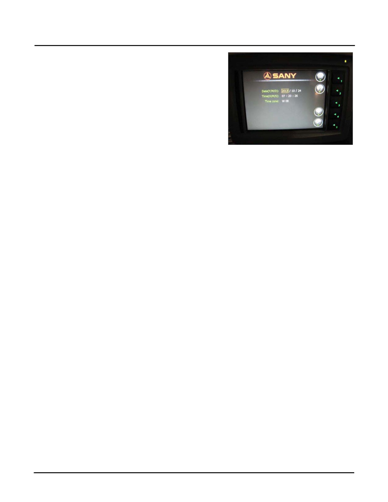
Set Date/Time Setting - First Time
1. Press Key 1 to go back to the System Setting screen.
2. Press Key 4 to go down the list to Date/Time Setting
and then Press Key 5 to accept. (See “Time Setup” on
page 3-33).
Fig. 4-36
4-27
Combined Instruments Display/Monitor Settings
SY335 Excavator
3. Press Key 2 to start/stop modifying the value of digit at
where the cursor is located.
4. Press Key 4 to switch between the increase/ decrease
keys and left-right keys.
5. Press Key 5 to accept time setup and return to previous
page.
Fig. 4-37
4-28
SY335 Excavator
Engine Procedures
ENGINE PROCEDURES
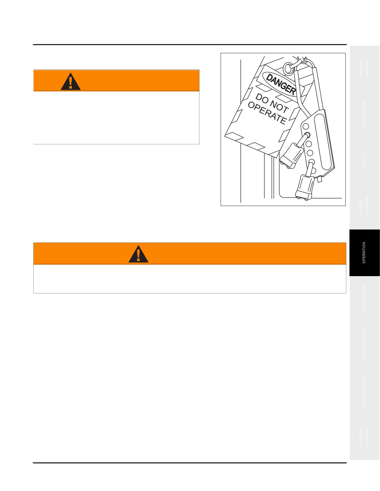
WARNING
Never attempt to start the machine if it has been
locked out by maintenance personnel. If in
doubt, contact the maintenance supervisor.
Failure to follow this can cause damage to the
machine, and could lead to serious injury or
death.
NOTE: Check the work area to be sure all personnel
and equipment are clear from your machine.
Before starting the machine, sound your
horn to warn others you are about to start the
machine.
Starting and shutdown procedures for most diesel engines
Fig. 4-38
are generally the same. Therefore, use the following
procedures except where specific differences are noted.
(Refer to the applicable engine manufacturer’s manual for detailed procedures.)
WARNING
Diesel engine exhaust can be harmful to your health or even fatal. Operate the engine only in a
well-ventilated area or vent the exhaust to the outside. Failure to observe and follow this
warning could result in personal injury or death.
Cold Weather Operation
The following recommendations are for operating Sany excavators in very low (i.e., sub-zero) temperatures.
NOTE: Detailed cold weather starting and operating procedures are covered in the engine manual.
This machine must have appropriate hydraulic oil, lubricants and other auxiliary items required for operation in
sub-zero temperatures. Individual machine functions should be operated to ensure they are sufficiently warmed
prior to performing work. Contact your Sany representative for recommended lubricants and fluids for cold
weather operations.
Operation of machine at full rated capacities in temperatures between 0°F (-18°C) and -40°F(-40°C) or lower
should be accomplished only by competent operators who possess the skill, experience, and dexterity to ensure
smooth operation. Shock loading must be avoided.
The correct grade of oil for the prevailing temperature must be used in the crankcase. Diesel fuel must have a pour
point of 10°F (6°C) less than the lowest expected temperature.
4-29
Engine Procedures
SY335 Excavator
Cold weather operations requires additional precautions:
•
Do not touch cold metal surfaces that could cause you to freeze to them.
•
Keep the machine clear of all ice and snow.
•
Allow sufficient time for the hydraulic oil to warm up.
•
Park the machine in an area where it will not freeze to the ground.
Engine Start Procedure
CAUTION
Do not spray starting fluid into the air inlet. The spray will contact the heater elements and
could explode causing equipment damage and personal injury.
CAUTION
NEVER attempt to start the machine if it has been locked-out by maintenance personnel or if
the main power disconnect switch is in the OFF position. If in doubt, contact the maintenance
supervisor. Failure to observe and follow this caution may result in equipment damage,
improper equipment operation or personal injury.
Perform the following steps to start the engine:
NOTE: Detailed cold weather starting and operating procedures are covered in the engine manual.
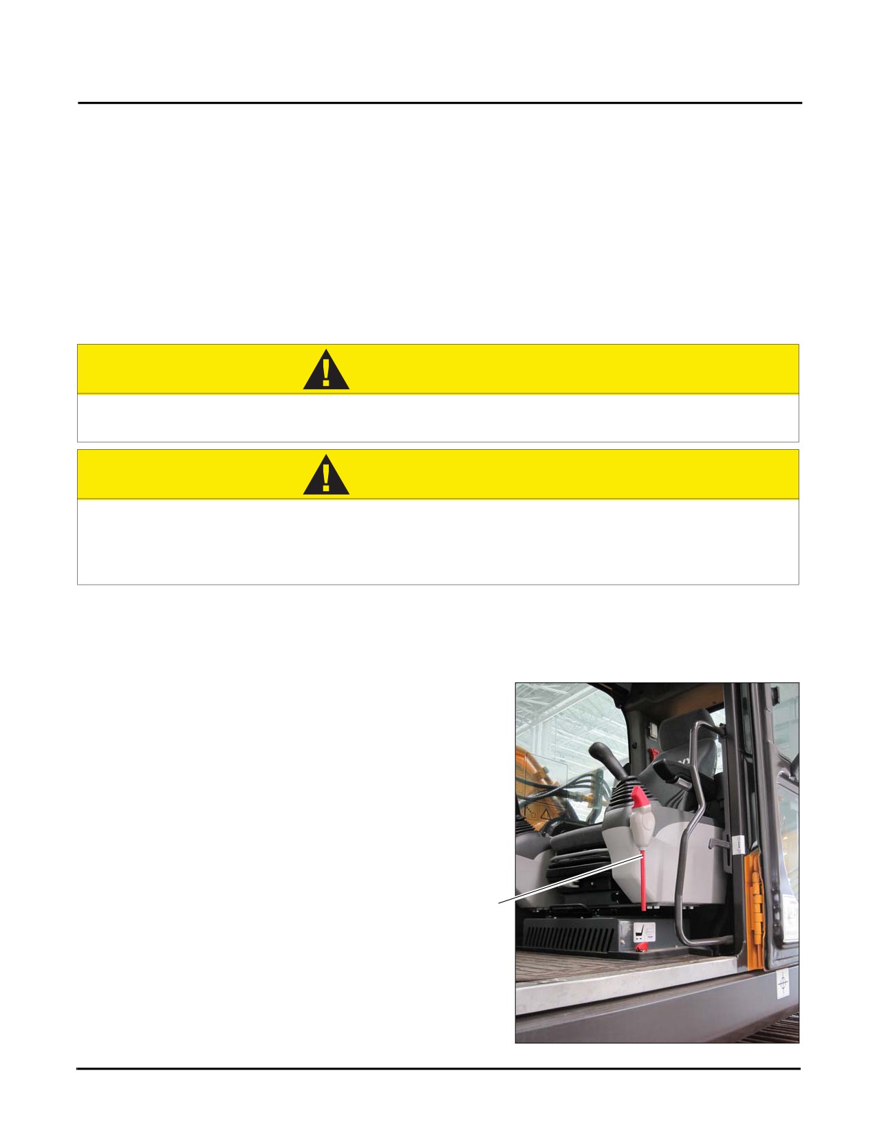
1. Set the hydraulic lockout lever (a) to the LOCKED
position.
a
Fig. 4-39
4-30
SY335 Excavator
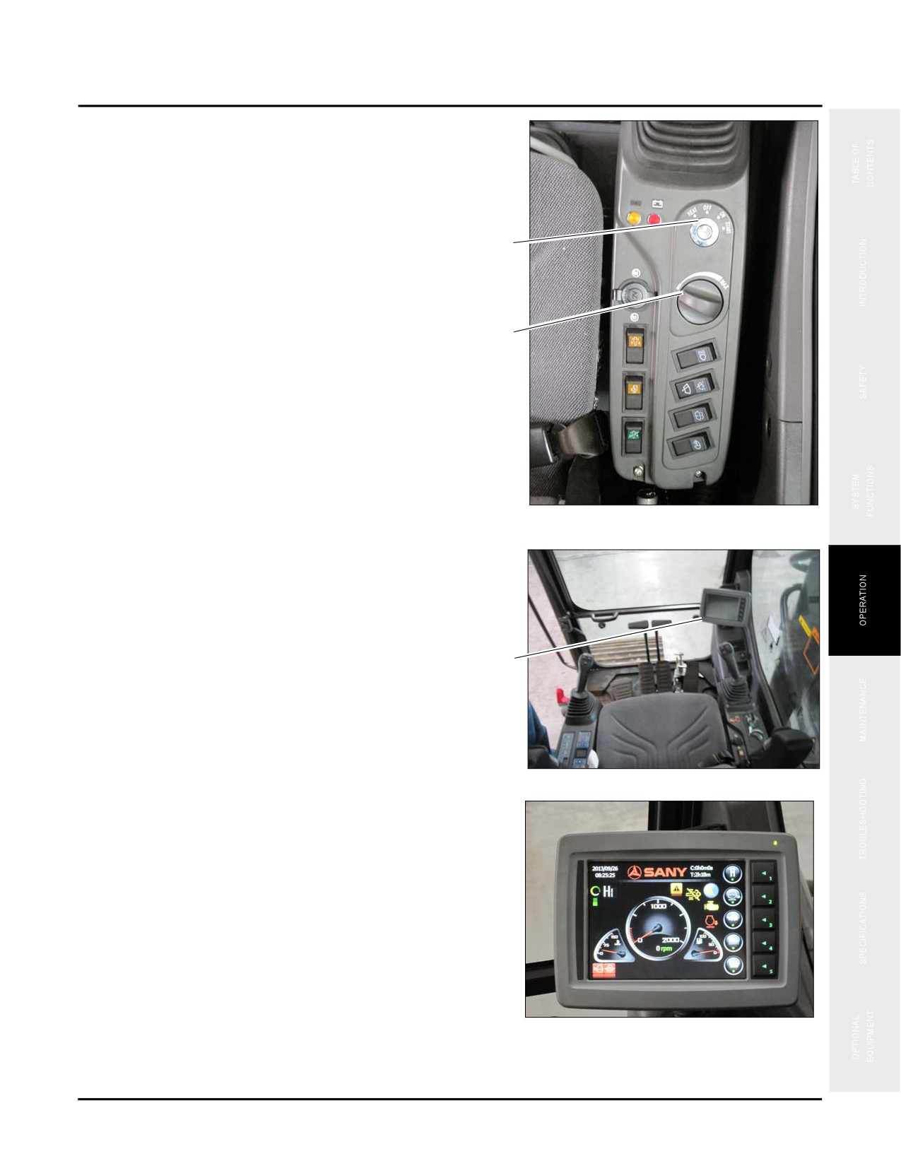
Engine Procedures
2. Set the throttle (b) to the MIN position.
3. Turn the ignition key (c) from OFF to ON.
c
b
Fig. 4-40
The monitor (d) displays the default screen two seconds
after the key is turned to the ON position. The display
allows access to:
•Displaying running parameters
•Viewing machine configuration
d
•Viewing failure codes
•Throttle (rpm)
•Setting up system clock
•Setting up service hours
Fig. 4-41
•Setting up key parameters
NOTE: The warning indicator lights if a fault is
detected. A fault code displays near the
bottom of the display. Contact your local Sany
service representative to correct the issue.
Fig. 4-42
4-31
Engine Procedures
SY335 Excavator
4. Turn the ignition key to START and release it immediately when the engine starts.
NOTE: If the engine fails to start after five attempts, correct the malfunction before attempting further starts.
Immediately check the engine instruments and monitor for any alarm codes after starting. Shut down the engine if
an alarm is displayed on the display screen.(See “Main Menu Functions” on page 3-30)
NOTICE
Never crank the engine for more than 15 seconds. If the engine fails to start after 15 seconds,
stop and allow the starter motor to cool for at least 10 seconds before attempting another
start. Failure to observe and follow this warning could result in equipment damage.
Idle the Engine
Idling the engine unnecessarily for long periods of time wastes fuel and fouls injector nozzles. Unburned fuel
causes carbon formation, oil dilution, formation of lacquer or gummy deposits on the valves, pistons, and rings,
and rapid accumulation of sludge in the engine.
NOTICE
NEVER race the engine during the warm-up period and NEVER operate the engine beyond the
governed speed. Engine bearings, pistons, and valves may be damaged if these precautions
are not taken. Failure to observe and follow this warning could result in equipment damage.
Engine Shutdown
1. Retract the arm and bucket cylinders, lower the boom
front end to rest on the ground
2. Run the engine at idle speed (1000 rpm) for about 5
minutes.
Fig. 4-43
4-32
SY335 Excavator
Engine Procedures
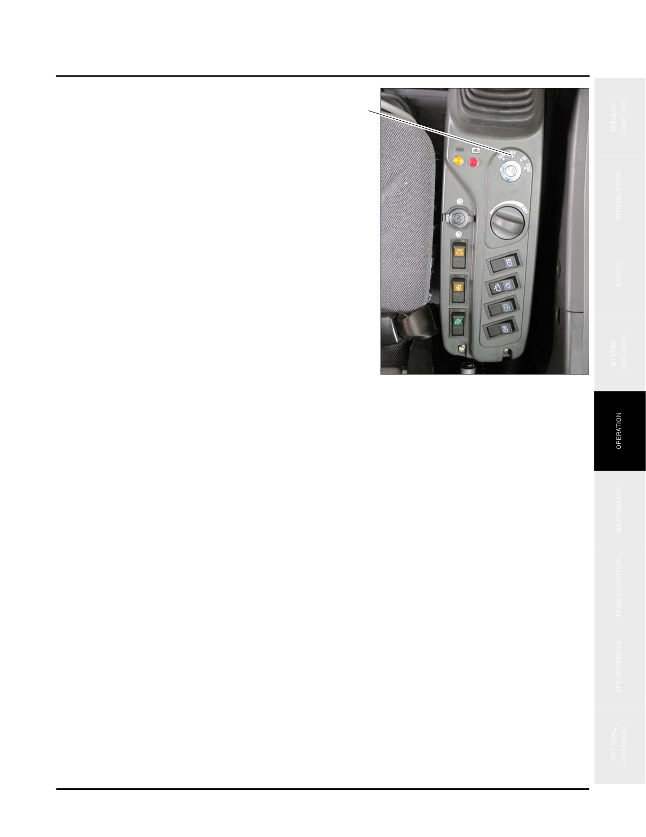
3. Turn the keyswitch (a) to the OFF position and remove
the key.
a
4. Operate all functional controls to relieve pressure on the
systems.
5. Remove the key from the switch.
Fig. 4-44
4-33
Travel Operations
SY335 Excavator
TRAVEL OPERATIONS
WARNING
1. Never allow any personnel to be within 26 ft (8m) of the rear of the machine to avoid injury.
2. Never allow any personnel to be around the machine while it is moving.
3. Be aware of all crush points on the machine and ensure that all personnel keep clear of
these areas.
All of these activities could result in serious injury or possibly death.
Preheat the Machine
NOTICE
Do not enter into operation immediately after starting the engine. Perform the following
preheat procedures to prepare the system for operations.
1. Adjust the throttle to make the engine run unloaded at low speed (1,000 rpm) for about five minutes.
2. Adjust throttle to make the engine run at moderate speed (1,400 rpm), and then slowly operate the bucket for
five minutes.
NOTE: See “Control Work Equipment” on page 4-46
3. Adjust the throttle to make the engine run at high speed (2000 rpm), and operate the boom, arm and bucket for
5-10 minutes.
4. Cycle each action of machine for several times before ending the preheat operation.
5. Continue to preheat the machine if coolant temperature fails to reach the middle of the display on the monitor
panel.
6. Check for excessive black exhaust smoke, very loud noise or excessive vibration. If found please notify your
distributor immediately or Sany for assistance.
4-34
SY335 Excavator
Travel Operations
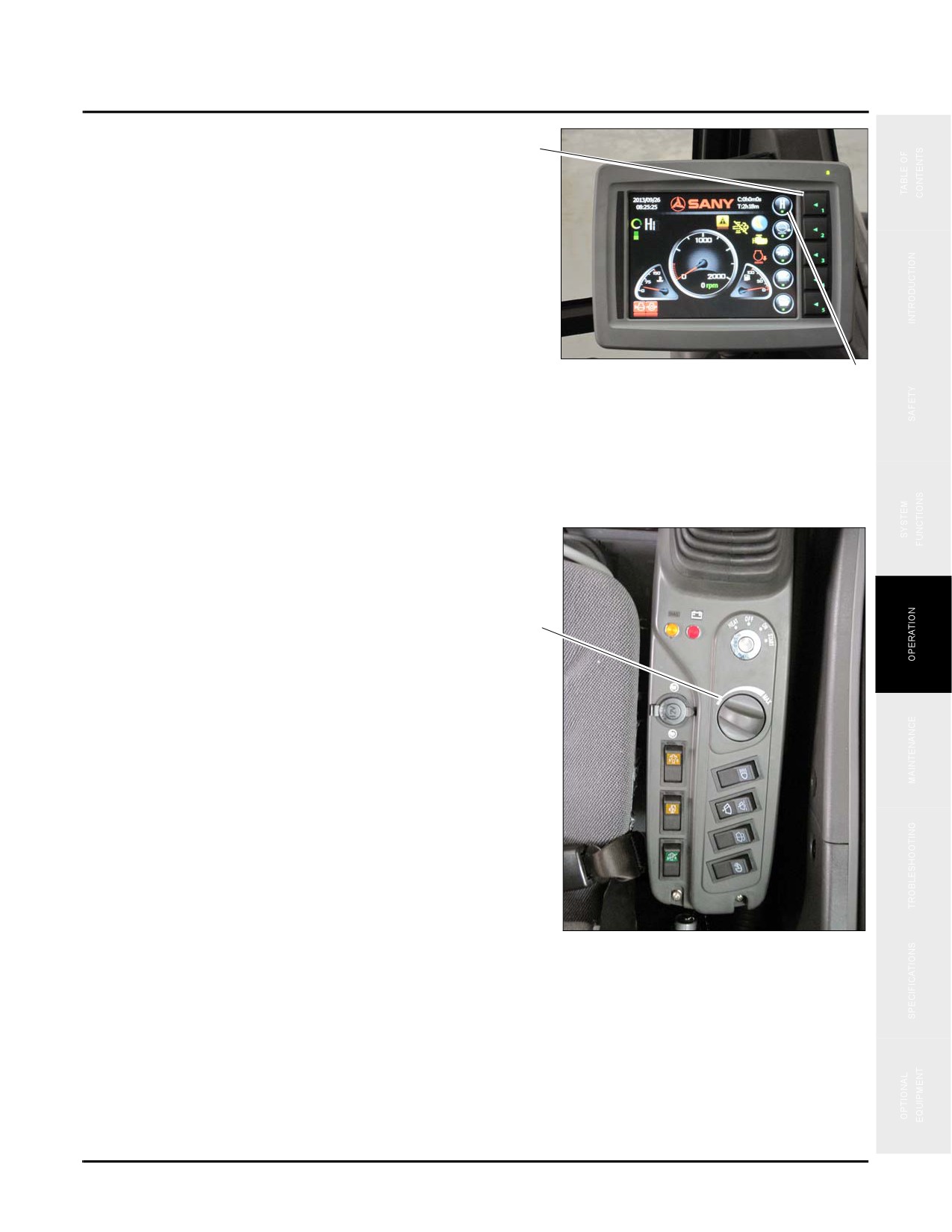
7. Press Key 1 to select the desired working mode.
1
NOTE: The working mode (2) is displayed in the
upper left corner of the monitor
screen.Working mode options are:
•
S: Standard duty: Used for normal excavating.
•
H: Heavy duty: Used for excavating in hard or
rocky ground.
•
L: Light duty: Used for light tasks such as digging
Fig. 4-45
in soft soil.
2
•
B: Breaker mode: Used when operating with
attachments such as a jackhammer.
Before Travel
1. Turn the throttle (a) clockwise to increase the engine
speed.
a
Fig. 4-46
4-35
Travel Operations
SY335 Excavator
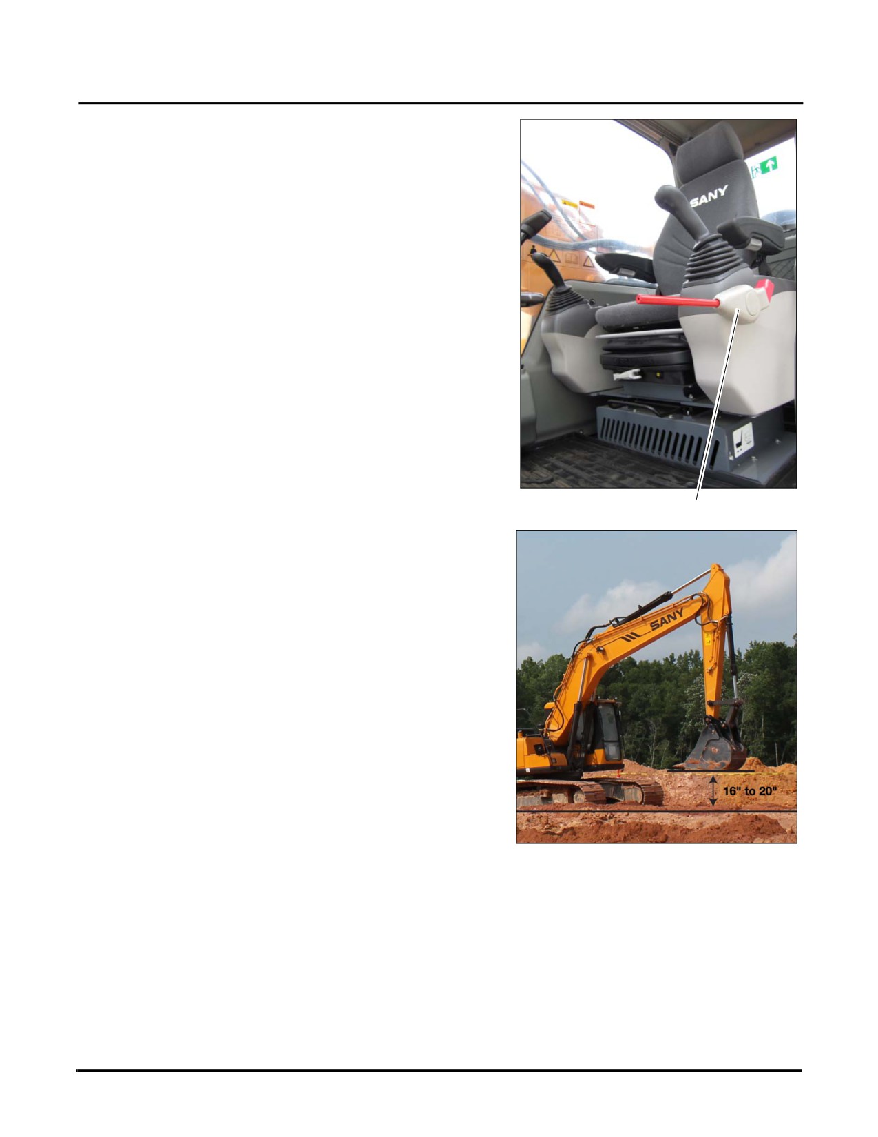
2. Place the hydraulic lockout control to the UNLOCKED
position (b).
Typical
Fig. 4-47
b
3. Retract the working equipment until it is 16 - 20 inches
(40 - 50 cm) above the ground.
NOTE: See “Control Work Equipment” on page 4-
46.
Fig. 4-48
4-36
SY335 Excavator
Travel Operations
4. Move the boom to ensure good all round visibility.
NOTE: See “Control Work Equipment” on page 4-
46.
Typical
Fig. 4-49
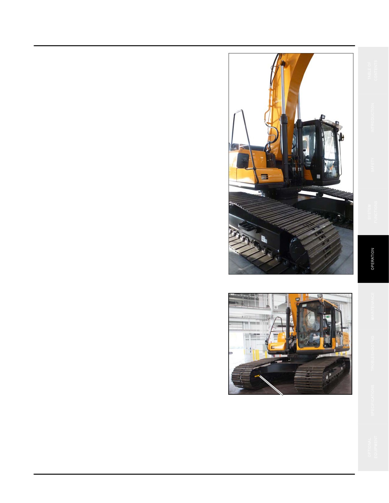
NOTE: Whenever possible rotate the cab to face in
the direction of the arrow (c) painted on the
inside of the crawler track. If the track frame
faces the rear
(behind the sprockets), the
machine will move in a direction opposite to
the operating direction of travel control lever
or pedal (Both the forward and backward
travels are reversed, and the leftward and
rightward travels as well).
Typical
c
Fig. 4-50
4-37
Travel Operations
SY335 Excavator
Right Turn
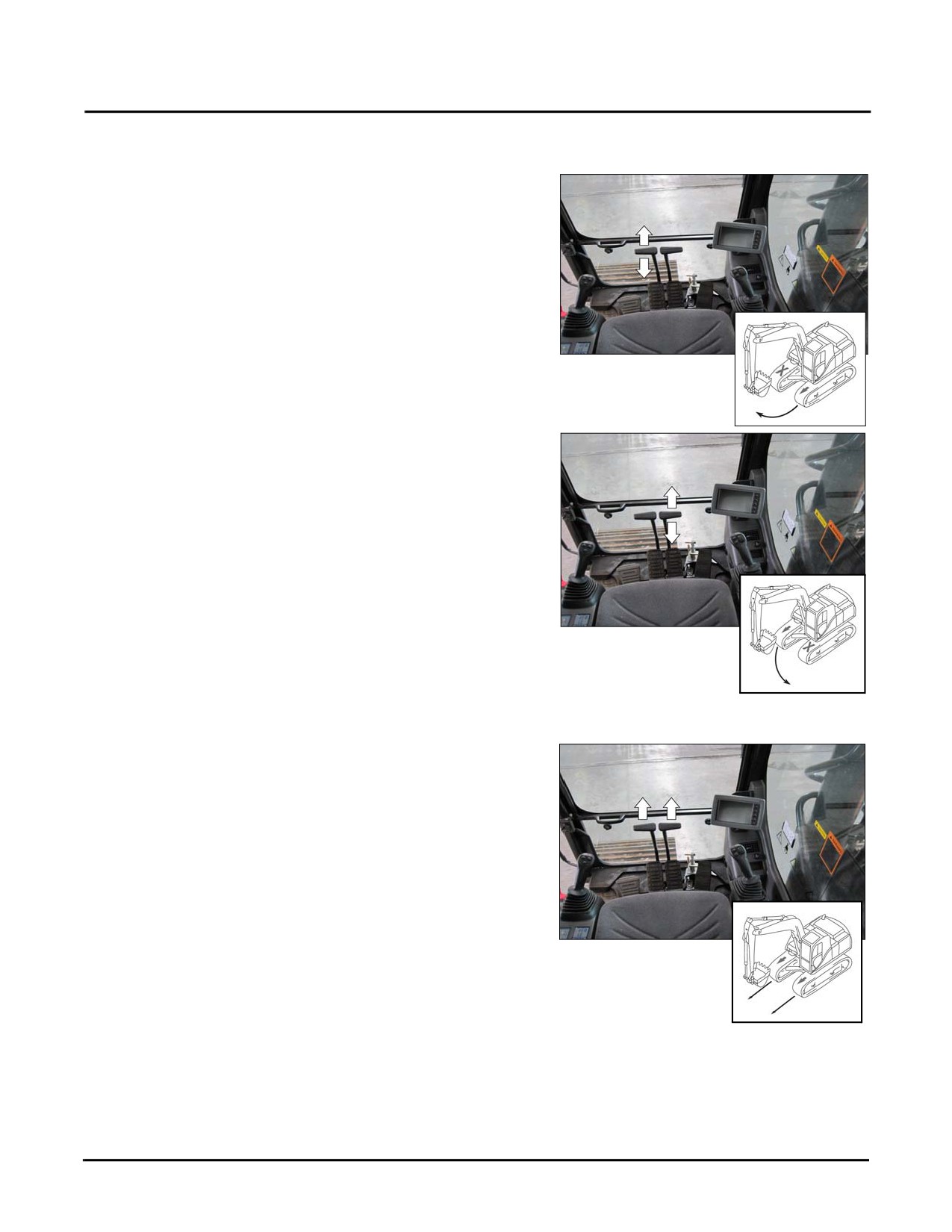
The left travel control lever causes the left track to move
forward or backward depending on which direction the
control is moved.
NOTE: Forward direction of the left track is shown in
the illustration.
The further the control is moved in ether direction the faster
the left track moves.
Fig. 4-51
Left Turn
The right travel control lever causes the right track to move
forward or backward depending on which direction the
control is moved.
NOTE: Forward direction of the right track is shown
in the illustration.
The further the control is moved in ether direction the faster
the right track moves.
Fig. 4-52
Straight Travel
Moving both controls causes both tracks to move forward or
backward depending on which direction the control is
moved.
NOTE: Forward direction of both tracks are shown in
the illustration.
The further the controls are moved in ether direction the
faster each track moves.
Fig. 4-53
4-38
SY335 Excavator
Travel Operations
Counter Rotate
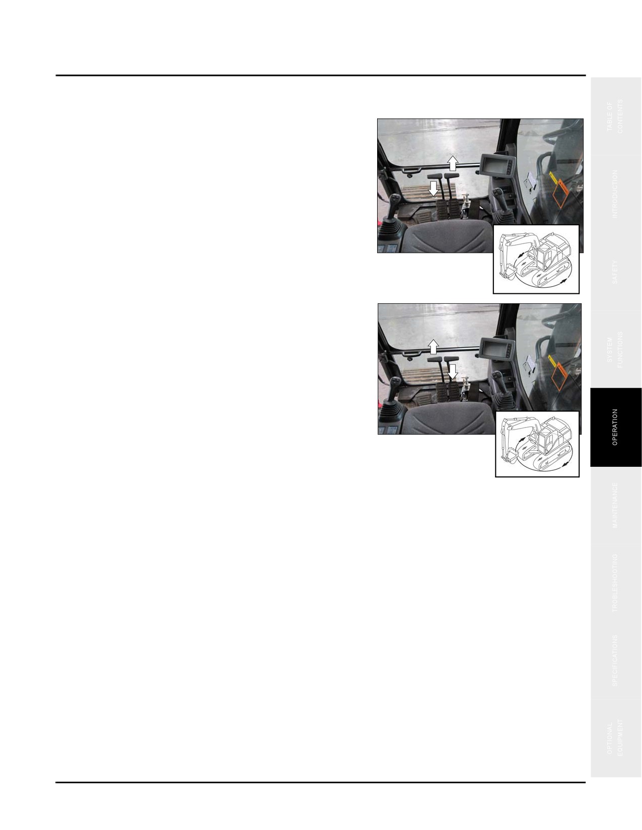
Left Zero Degree Rotation: Pushing the right lever
forward and pulling the left lever rearward causes a left zero
degree rotation of the machine.
Fig. 4-54
Right Zero Degree Rotation: Pushing the left lever
forward and pulling the right lever rearward causes a right
zero degree rotation of the machine.
Fig. 4-55
Slopes
Observe the following when operating an machine on a slope:
•
The slope - side-to-side or fore and aft - must not exceed 15%.
•
The hydraulic tank must be filled to the specified level (See “Hydraulic Oil Level” on page 4-15). The fuel
tank must be over half full.
•
Avoid holes, rocks, extremely soft surfaces, and other obstacles that might subject the machine to undue
stresses and possible tipover.
•
Position the bucket 16 - 20 inches (20 - 30cm) above the ground while traveling.
•
Always set the throttle and speed selector to maintain a slow speed while traveling up or down a slope.
•
Do not turn the machine while on a slope.
•
Do not travel in reverse on a slope.
4-39
Travel Operations
SY335 Excavator
Operations in Water
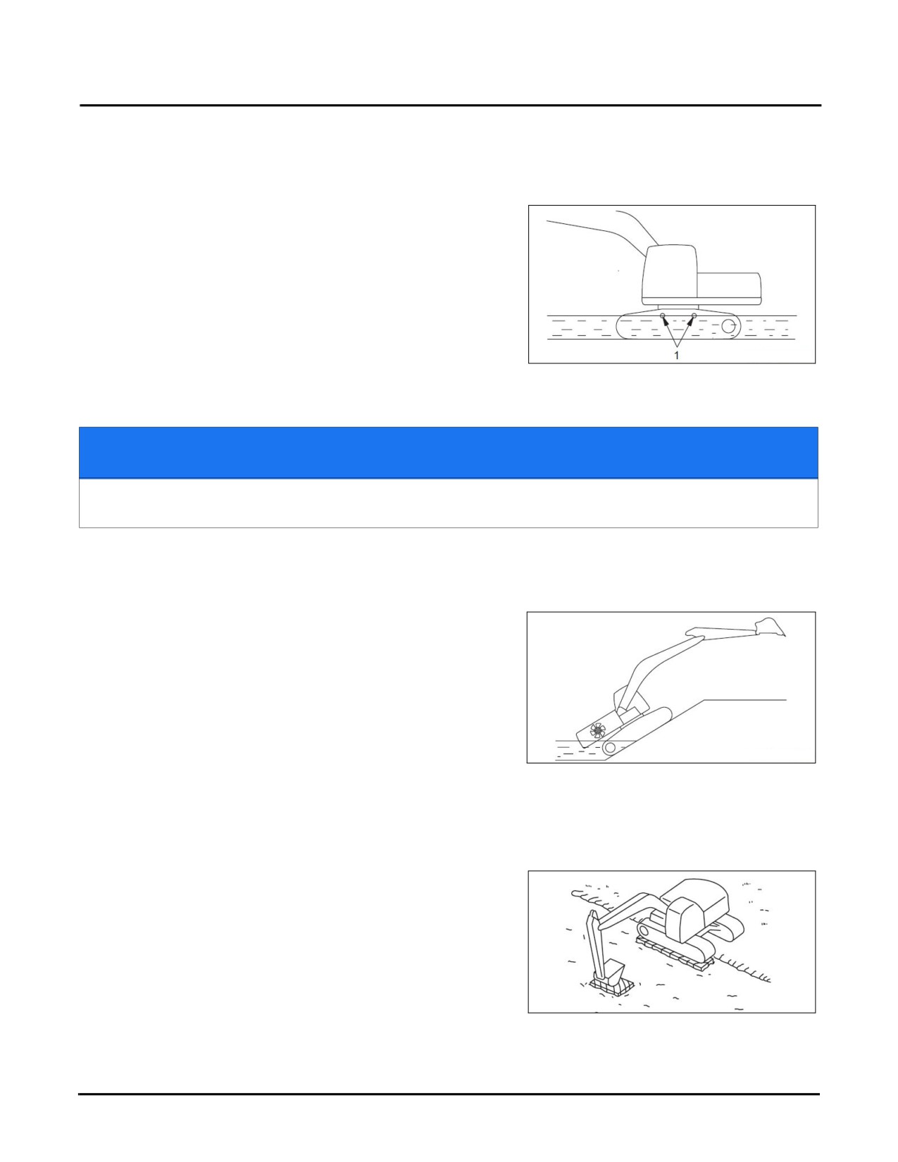
Observe the following when operating a machine in water:
•
Do not drive the machine into water where the
water level could reach the center of the carrier
rollers (1).
Fig. 4-56
NOTICE
If the swing bearing, swing gear and central swing joint are soaked in water, the drain plug
should be removed to drain mud and water then lubricate the mesh gear and swing bearing.
•
Do not operate the machine in water unless the foundation of the work site is strong enough to properly
support the machine.
•
Do not drive the machine out of water at an slope
greater than 15°, the engine cooling fan could be
damaged by immersion in the water.
•
Add grease to parts that have been soaked in water
until all the old grease is squeezed out of the
bearing.
Release Excavator from Mud
Fig. 4-57
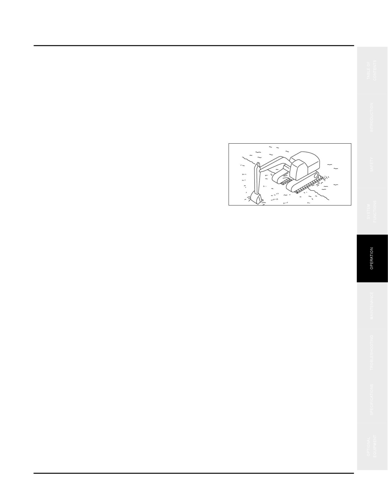
If the machine becomes stuck in mud, drive it out of the
mud using the following methods:
One Track Stuck
1. Position the boom and arm at an angle between 90° and
110°.
NOTE: See “Operator Controls” on page 4-23
2. Pivot the upper structure to position the boom over the
track that is stuck.
Fig. 4-58
4-40
SY335 Excavator
Travel Operations
3. Curl the bucket so that the back of the bucket contracts the ground. Use cribbing to provide a firm surface if
necessary.
4. Move the joystick forward to lower the boom to lift the track.
5. Place cribbing under the track.
6. Drive the machine out of the mud.
NOTE: See “Travel Operations” on page 4-34
Two Tracks Stuck
1. Position the boom and arm at an angle between 90° and
110°.
2. Pivot the upper structure to position the boom over the
front of the machine.
3. Curl the bucket so that the back of the bucket contracts
Fig. 4-59
the ground. Use cribbing to provide a firm surface if
necessary.
4. Move the joystick forward to lower the boom to lift the front of the tracks.
5. Place cribbing under the tracks.
6. Cut the bucket into the ground in front of the machine.
7. Retract the arm as done with normal excavating while driving the machine forward out of the mud.
4-41