SANY Excavator SY335 (Part Number: 11282013). Safety, Operation & Maintenance Manual - page 3
Product Specific Safety
SY335 Excavator
2-60
SY335 Excavator
System Functions
System Functions
Exterior Components
3-3
Cab Exterior
3-4
Cab Interior
3-5
Seat and Seat Belt
3-6
Left Control Console
3-8
Air Conditioning System - Control Panel
3-9
Radio Control Panel
3-11
Right Control Console
3-13
Indicator Lights
3-14
Ignition Switch
3-15
12V Power Supply
3-15
Throttle Control Dial
3-15
24V Power Outlet/Lighter
3-16
Work Lamp Switch
3-16
Manual Regeneration Switch
3-16
Memory Clear Switch
3-16
Regeneration Disable Switch
3-16
Head Lamp Switch
3-17
Windshield Washer Switch
3-17
Windshield Wiper Switch
3-17
Hydraulic Lockout Control
3-17
Emergency Stop Switch
3-18
Joystick Controls
3-19
SAE/BHL Selector Switch
3-19
SAE Mode
3-20
BHL Mode
3-21
Joystick Switches
3-22
Travel Controls
3-23
Automatic Deceleration Function
3-24
Fuses and Batteries
3-25
Batteries and Power Disconnect Process
3-26
Battery
3-26
Safety, Operation & Maintenance Manual — November 28,
2013
3-1
System Functions
SY335 Excavator
Power disconnect process
3-26
Combined Instruments Display/Monitor
3-28
Combined Instrument Display screen
3-28
Function Icons
3-31
Function Keys
3-31
System Information
3-31
Main Menu Functions
3-33
Engine and Throttle Signals
3-34
Pilot (Hydraulic Control) Pressure Signals
3-34
Main Pump Signals
3-34
Machine Configuration
3-35
Fault Information
3-35
System Language Selection
3-36
Machine Configuration Setup
3-36
Time Setup
3-36
Service Hours Setup
3-37
WARNING
Read and understand all safety precautions and
instructions in this section of this manual before
reading the other sections of this manual or any other
manuals provided with this crawler hydraulic crane and
before operating or servicing the crawler hydraulic
crane. Failure to do this can cause property damage,
personal injury or death.
3-2
SY335 Excavator
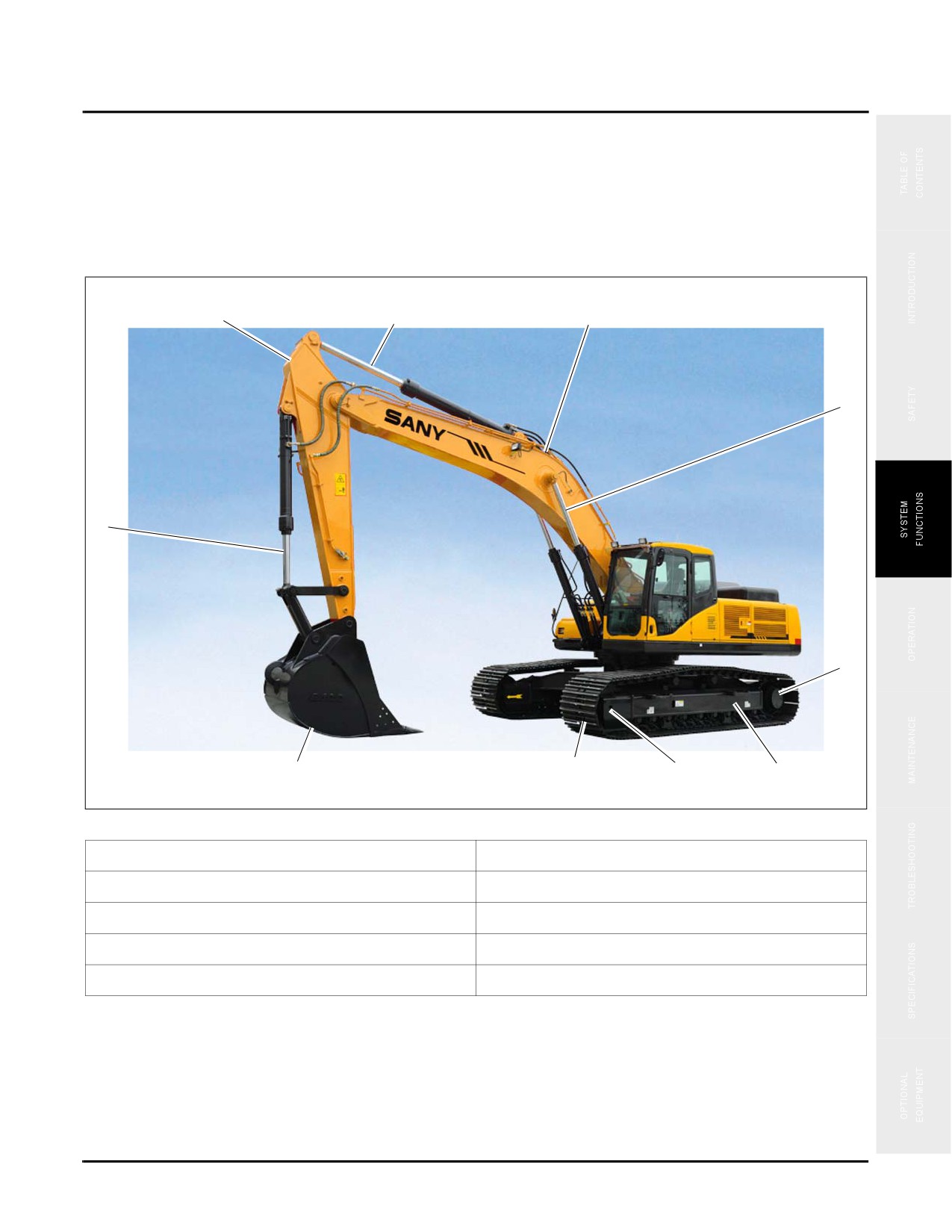
Exterior Components
EXTERIOR COMPONENTS
This section provides information regarding the basic description and overview of all the controls, alerts and
operating systems on the excavator unit. It is important to study and become familiar with all systems before
proceeding with any operations. Be sure you have and read and understand the information in the Safety section of
this manual.
3
4
5
6
2
7
1
10
9
8
Fig. 3-1
1. Bucket
6. Boom cylinder
2. Bucket cylinder
7. Drive sprocket
3. Arm
8. Track frame
4. Arm cylinder
9. Idler wheel
5. Boom
10. Track shoe
3-3
Cab Exterior
SY335 Excavator
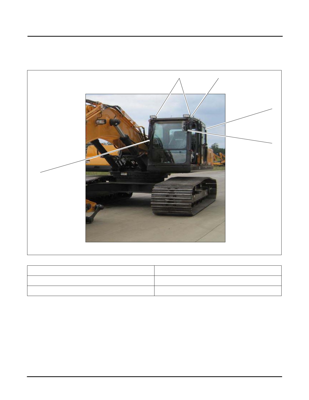
CAB EXTERIOR
1
2
3
4
5
Fig. 3-2
1. Work lamps
4. Rear-view mirror
2. Overhead protection shield
5. Windshield wiper, see page 3-17
3. Door
3-4
SY335 Excavator
Cab Interior
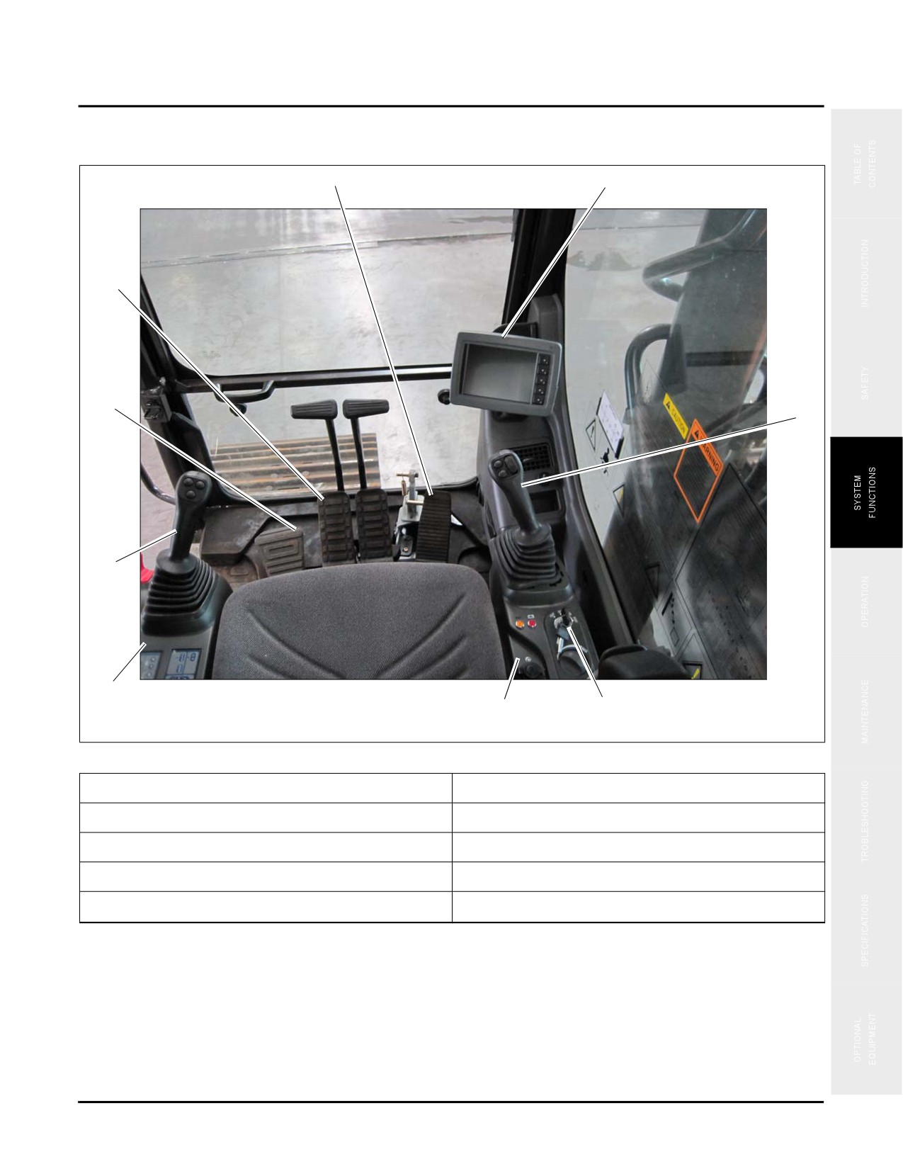
CAB INTERIOR
5
6
2
4
3
7
2
1
9
8
Fig. 3-3
1. Left control console, see page 3-6
6. Combined instrument display, see page 3-28
2. Left joystick, see page 3-22
7. Right joystick, see page 3-22
3. Foot rest
8. Ignition switch, see page 3-15
4. Travel controls, see page 3-23
9. Right control console, see page 3-13
5. Optional equipment control pedal
3-5
Cab Interior
SY335 Excavator
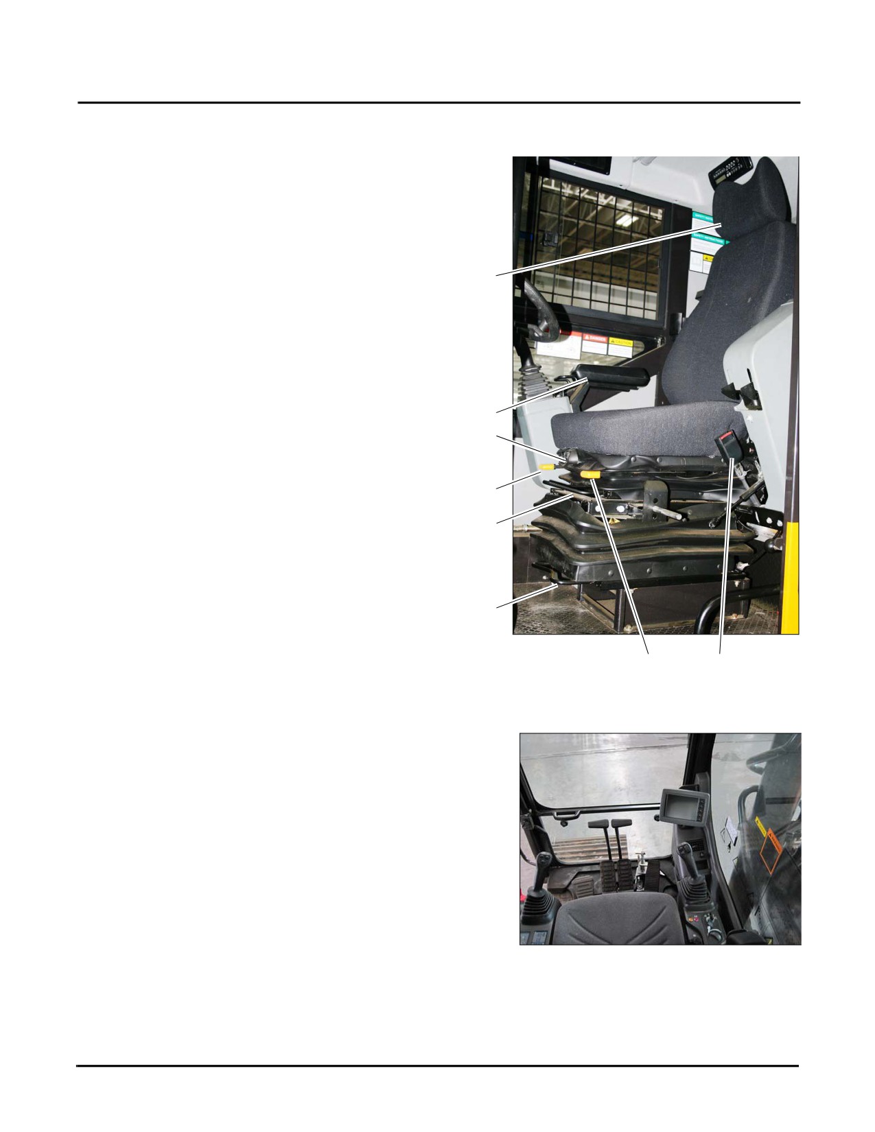
Seat and Seat Belt
A multi-position, adjustable seat is provided for operator
comfort. The front/rear position, up/down positions, and the
front/rear incline angle seat back can be adjusted.
The seat has two armrests (a).
The seat belt
(b) keeps the operator securely in the
c
operator’s seat.
The headrest (c) can be raised or lowered by grasping the
headrest with both hands and pulling it up or pushing it
down.
The seat’s air suspension can be adjusting by turning the
a
knob
(d) clockwise to increase the firmness or
d
counterclockwise to decrease the firmness.
To adjust the angle of the seat back, pull up on the seat back
e
adjusting lever (e).
f
To move the seat forward or backward, pull up on the
adjusting lever (f) and slide the seat forward or backward
until the desired position is reached.
To move the seat base forward or backward, pull up on the
g
adjusting lever
(g) and slide the seat base forward or
backward until the desired position is reached.
Fig. 3-4
h
b
Typical
To adjust the angle of the seat base, pull up on the adjusting
lever (h).
Be sure your vision is clear in all directions as viewed from
the seated position.
Never allow other personnel to ride with you inside the
operator cab regardless of the situation and never bring
objects into the operator cab that could restrict your
movement or vision in any manner.
Close or latch all doors or windows in place.
Fig. 3-5
3-6
SY335 Excavator
Cab Interior
Fasten the seat belt snuggly around your waist and prepare
to start the machine for work operations.
NOTE: See “Seat and Seat Belt” on page 4-20 for
additional information.
Be sure your vision is clear in all directions as viewed from
the seated position.
Check the work area to be sure all personnel and equipment
are clear from your machine. Before starting the machine,
sound your horn to warn others you are about to start the
machine.
ACN0019
Fig. 3-6
3-7
Cab Interior
SY335 Excavator
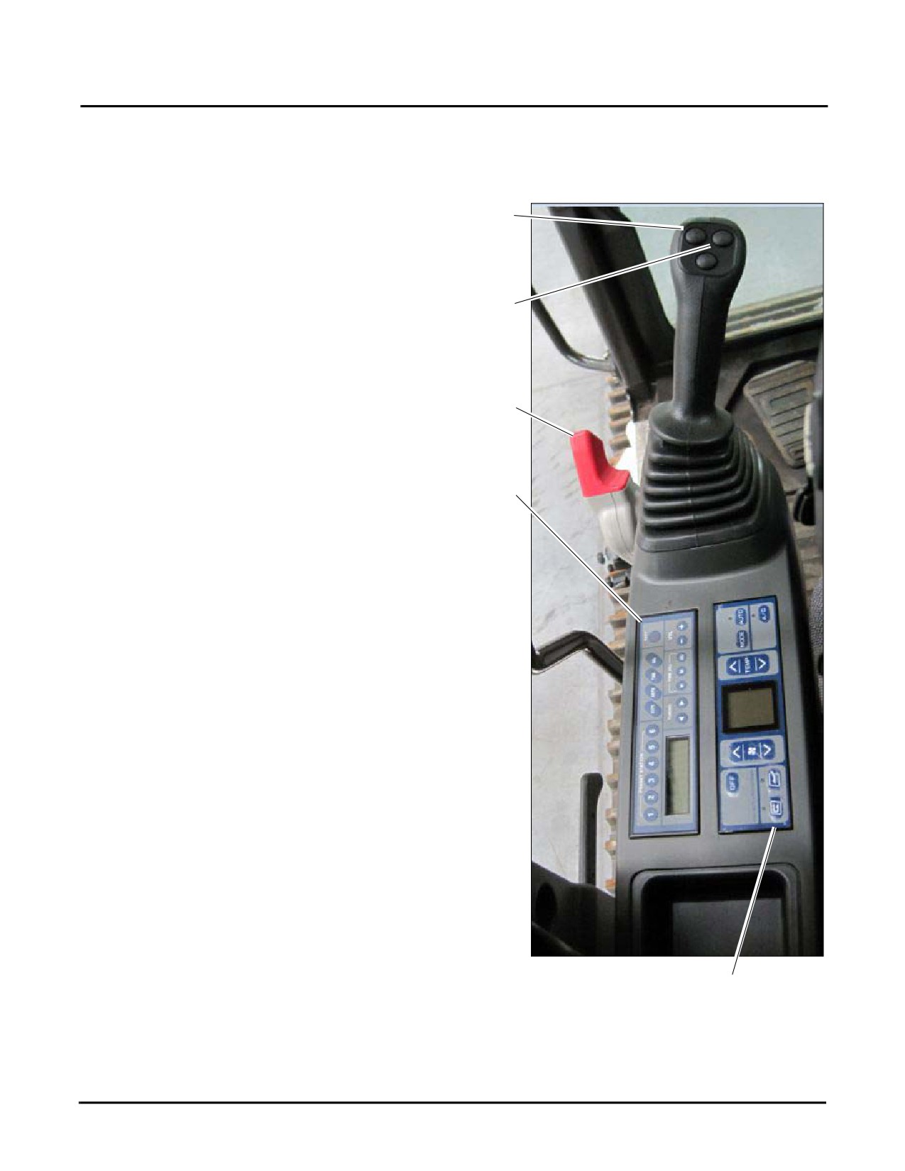
Left Control Console
The left control console is to the left of the operator when seated and facing toward the windshield.
The left control console contains the following items:
1
1. Left joystick, see page 3-22
2. Slewing optional equipment buttons, see page 3-22
2
3. Hydraulic lockout control, see page 3-17
4. Radio control panel, see page 3-11
5. Air conditioning control panel, see page 3-9
3
4
Fig. 3-7
5
3-8
SY335 Excavator
Cab Interior
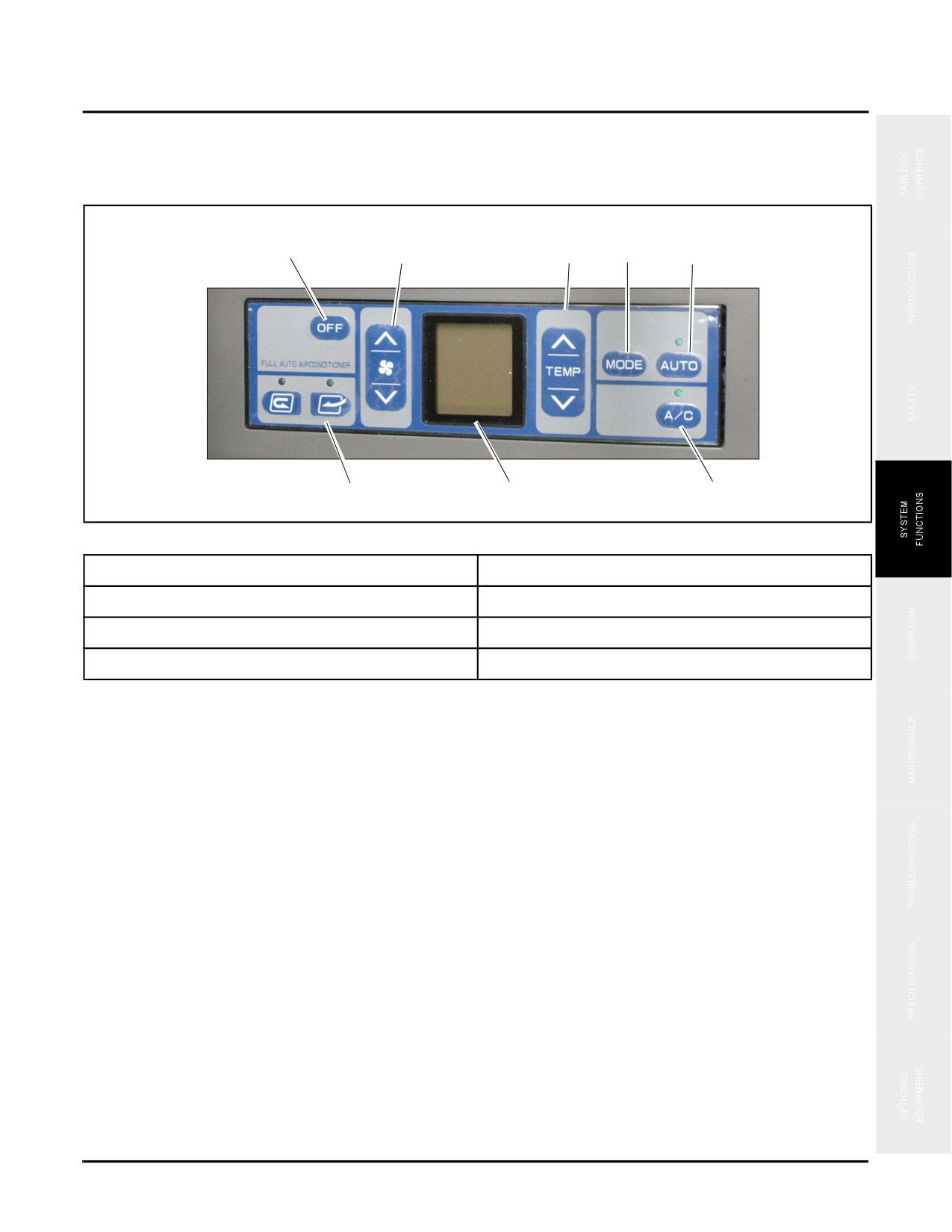
Air Conditioning System - Control Panel
1
2
3
4
5
6
7
8
Fig. 3-8
1. OFF switch
5. Auto mode switch
2. Fan control switch
6. Fresh air/recirculation shift switch
3. Temperature setup switch
7. LCD
4. Vent mode setup switch
8. A/C power
1. OFF switch
This switch is used to stop the fan and air conditioner.
2. Fan control switch
The switch is used to regulate the volume of air flow, which can be set to any of six levels.
3. Temperature switch
This switch is used to control the temperature inside the cab. Temperature can be set between 64° F (18° C) and 90°
F (32° C)
4. Vent Mode Set-up switch is used when setting up manual control
5. Automatic control switch
This switch can be used to set air flow, outlets and fresh air or circulation automatically according to the preset
temperature.
NOTE: When automatic control is selected, the airflow may remain at HIGH if the temperature is set at 64° F
(18° C) or 90° F (32° C)
3-9
Cab Interior
SY335 Excavator
6. Fresh air/recirculation switch
This switch open or closes the fresh air inlet.
7. LCD display
The LCD display shows the preset temperature, air flow and outlet position during operation. Press the OFF switch
to turn the display off.
8. Air conditioner switch
The air conditioner switch is used to switch on/off the air conditioner or its operation (cooling, dehumidifying and
heating).
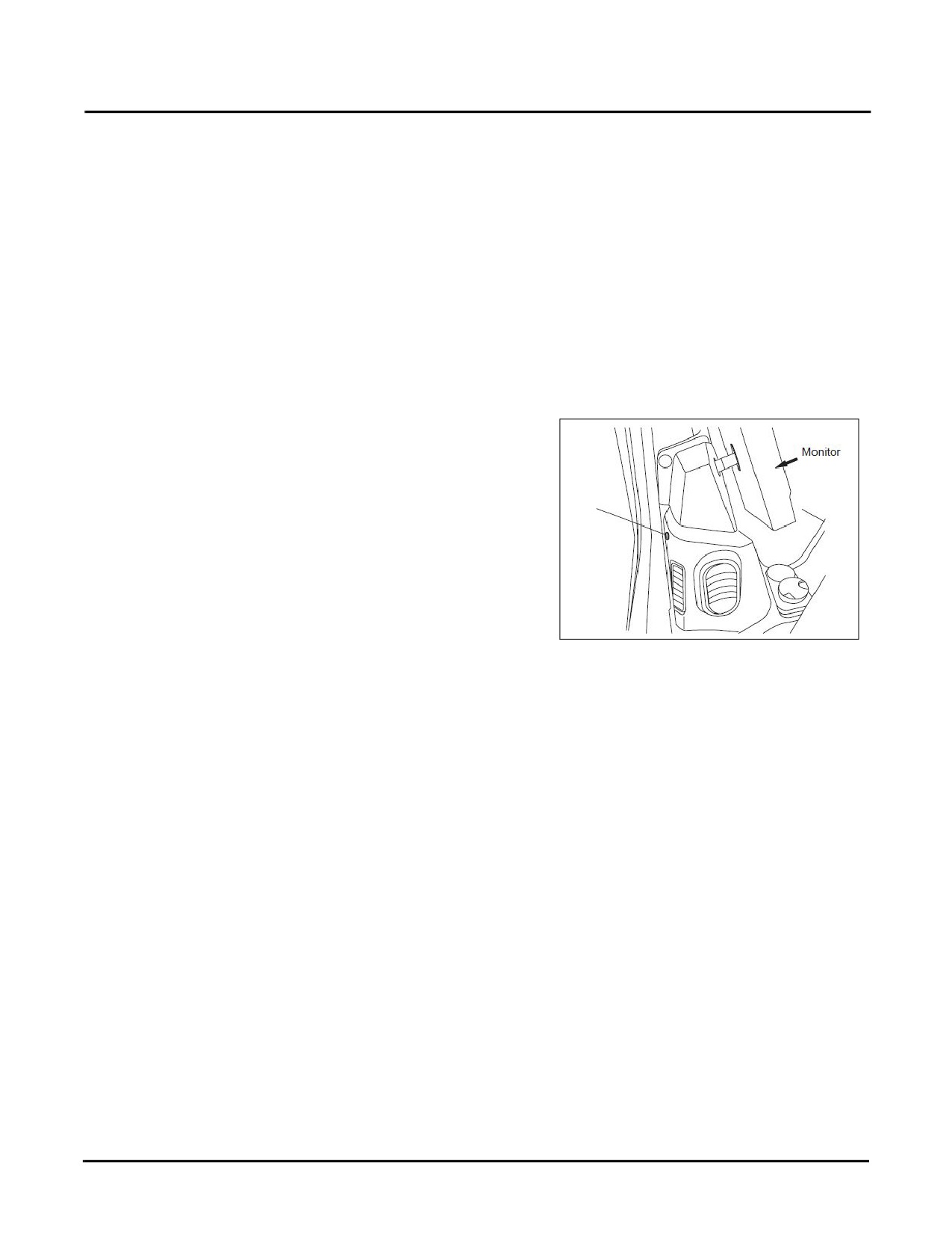
9. Sunlight sensor
The sunlight sensor (1) will adjust the air flow to match the
variation of temperature caused by direct sunlight.
1
10. A/C operation precautions
•
When running the air conditioning system, always
start with the engine running at a low speed. Avoid
starting the air conditioner when the engine is
Fig. 3-9
running at a high speed, or possible damage to the
air conditioner may result.
•
If water should get on control panel or sunlight sensor, an unexpected failure may result. Always keep
these components clear and free from water.
•
“A/C controller failure” will be displayed on the air conditioner control panel if there are problems with
your a/c unit. If this occurs please contact your Sany distributor to investigate and repair it.
3-10
SY335 Excavator
Cab Interior
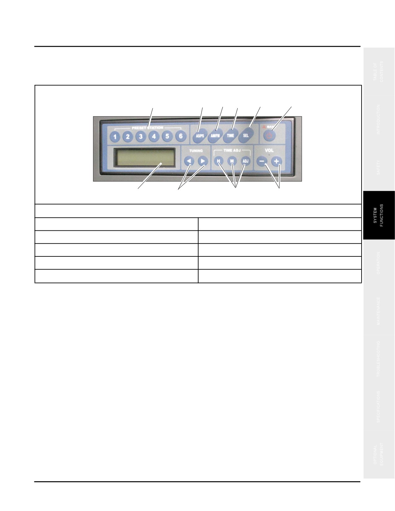
Radio Control Panel
6
5
4
3
2
1
7
8
9
10
Fig. 3-10
1. Power switch
6. Preset stations (1,2,3,4,5,6)
2. Sound effect switch
7. LCD
3. Time display
8. Tuning keys
4. FM/AM selector
9. Time adjusting keys
5. AS/PS key
10. Volume control
1. Power switch
Push the power switch in order to turn on the radio. The frequency is shown on the LCD display.
2. Tone adjustment
When this switch is pressed, the tone will be displayed in turn at each pressing:
•
VOL → BAS → TRE → Balance. The device returns to frequency display when no operation is
performed within 5 seconds.
3. Time display
When the frequency is displayed, press the switch to show local time for 5 seconds. The display returns to display
frequency after 5 seconds.
4. FM/AM band selector
Press the switch to select the desired band. Pressing the key each time toggles the band between FM and AM.
3-11
Cab Interior
SY335 Excavator
5. AS/PS key
This key is used to auto scan and preset stations.
Auto Scan:
•
When tuning in the radio, pressing the AS/PS key allows you to scan each preset station, which will be
played for 10 seconds, while the number of the preset station scanned is blinking on the display. If you
want to tune in a station, press the key again.
6. Preset Stations:
When tuning the radio, depressing the AS/PS key for more than 2 seconds will activate the auto scanning of all
current stations. The six radio stations having the strongest signal will be stored in turn to the six keys (1-6).
•
Once the preset is activated you can key them in to play any of the selected stations.
7. LCD display
The band, radio frequency, preset number and time will be shown on the display.
8. Tuning key
Press the Tuning key to change frequency.
9. Time adjustment
Use these keys to adjust the time.
•
H: Hour
•
M: Minute
•
ADJ: Set to 00 minute
10. Volume control
•
Press the key “+” to increase sound volume.
•
Press the key “-” to decrease sound volume.
3-12
SY335 Excavator
Cab Interior
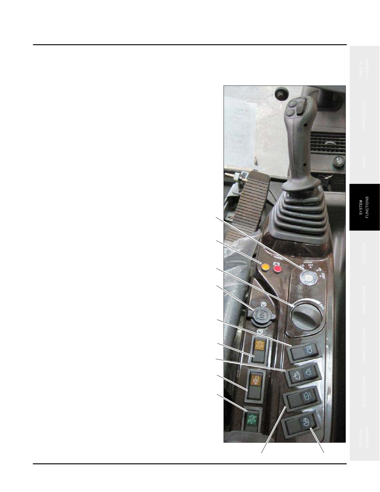
Right Control Console
The right control console is to the right of the operator when seated and facing toward the windshield.
The right control console contains the following items:
1. Ignition switch, see page 3-15
2. Indicator lights, see page 3-14
3. Throttle control dial, see page 3-15
4.
12V power supply, see page 3-15
5. Work lamp switch, see page 3-16
6. Manual regeneration switch, see page 3-16
7. Windshield wiper switch, see page 3-17
1
8. Memory clear switch, see page 3-16
2
9. Regeneration disable switch, see page 3-16
10. Windshield washer switch, see page 3-17
3
11. Head lamp switch, see page 3-17
4
5
6
7
8
9
Fig. 3-11
10
11
3-13
Cab Interior
SY335 Excavator
Indicator Lights
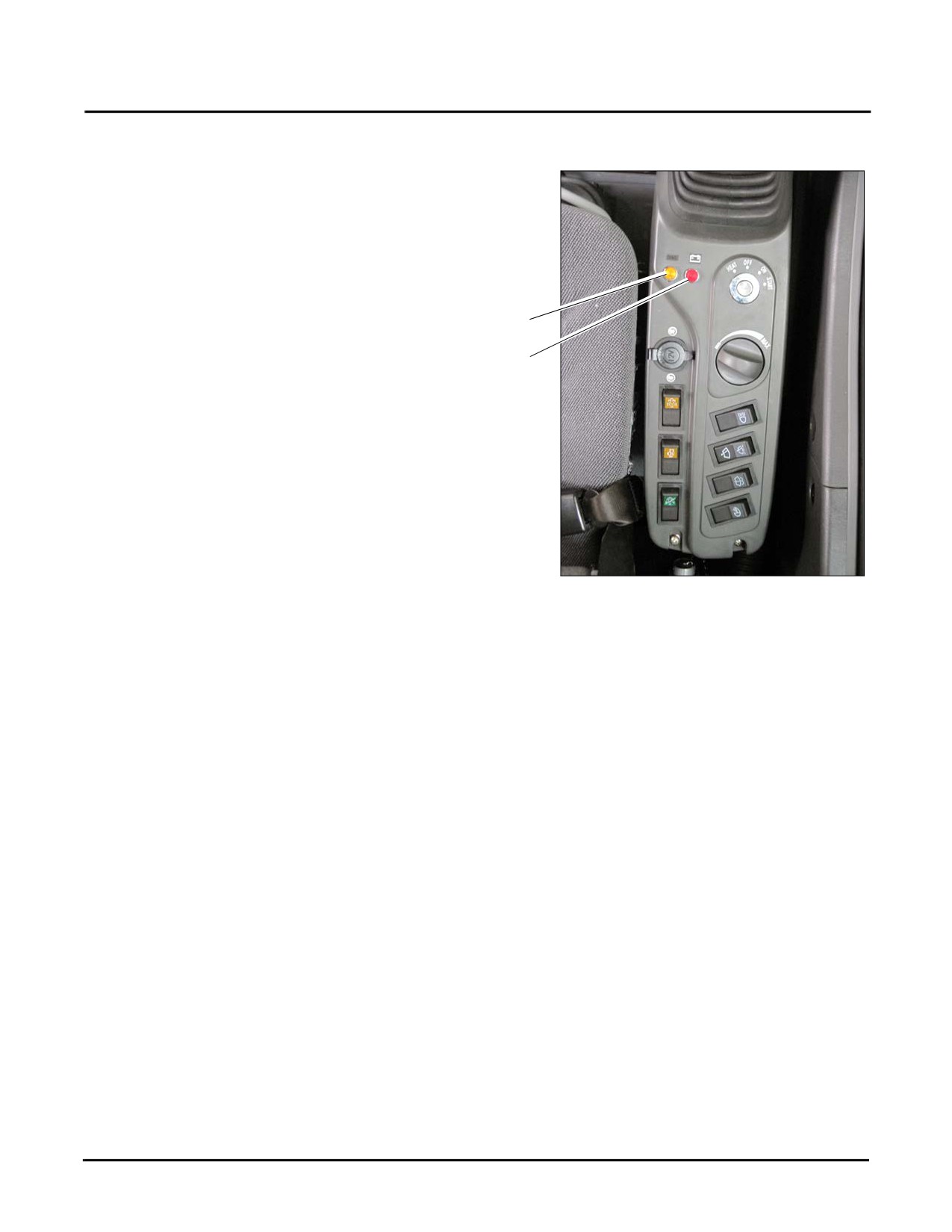
The indicator lights are for:
1. Failure indicator
The failure indicator is normally off to indicate the
excavator is free from failure. If this light starts to flash
frequently there is a system failure and you will need to turn
the machine off and notify your Sany distributor.
1
2. Charging indicator
2
The charging indicator should light up to a bright red when
the ignition switch is turned to the ON position. This light
will go off when the engine is running and the alternator is
charging the electrical system.
Fig. 3-12
3-14
SY335 Excavator
Cab Interior
Ignition Switch
NOTICE
If the engine does not stop at low idle speed, the service life of engine will be reduced. Except
for emergencies, never shut off the engine while it is running at high speed. Stopping the
engine at high speed may cause the cylinder cap to crack or may damage the bearing of the
turbocharger.
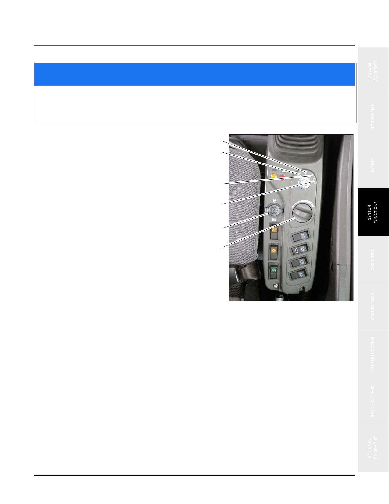
The start switch is used to turn on/off the engine.
1
1. OFF This position allows to insert or remove the key.
2
All switches of the electrical system (except for outdoor
lamps) are cut off and the engine is shut down.
2. HEAT Hold the key in this position to preheat the
3
engine. Releasing the key, it will return to the OFF
position.
4
3. ON Electric current passes through the charging and
lamp circuits. Leave the ignition key in the ON position
5
when the engine is running.
6
4. START This is engine starting position. Hold the key in
this position during starting. Release the key
immediately after the engine is started. The key will
return to the ON position (3) automatically.
12V Power Supply
This 12 volt charger (5) can be used to charge your mobile
Fig. 3-13
phone, or other 12 volt items of equipment.
Throttle Control Dial
The throttle control dial (6) is used to adjust engine speed and output power. Turn the dial clockwise to increase
speed and counterclockwise to decrease speed.
•
Low Idle (MIN): Turn it counterclockwise to the end.
•
Full Speed (MAX): Turn it clockwise to the end.
3-15
Cab Interior
SY335 Excavator
24V Power Outlet/Lighter
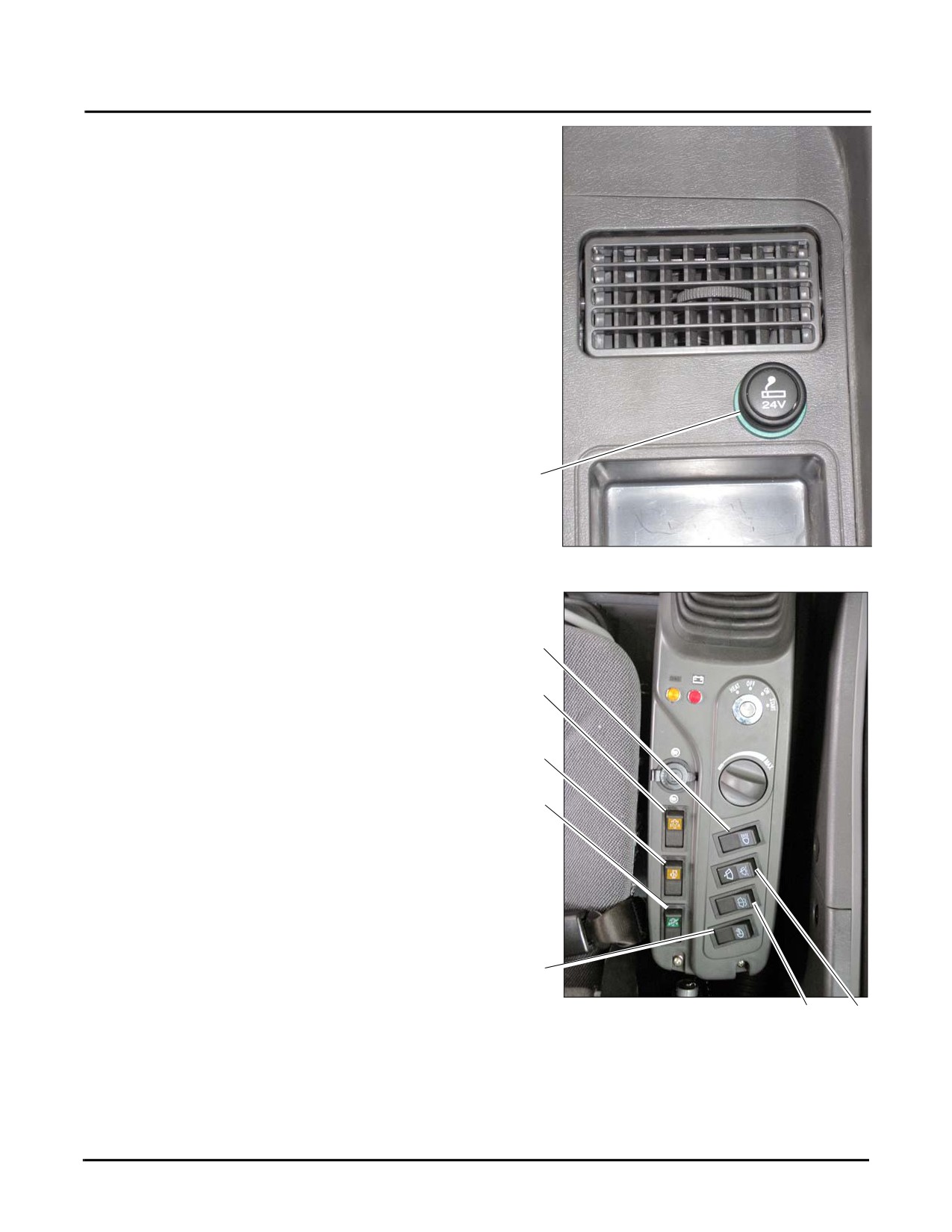
This socket (1) can be used as a power source for devices
rated not more than 240 W (24V×10A).
NOTE: This is a 24V device, never use it as a power
source for a 12V device.
Push in the power outlet/lighter to activate it, it returns to its
original position after a few seconds. Pull it out to light a
cigarette.
1
Fig. 3-14
Work Lamp Switch
This switch (1) is used to turn the boom lamps on/off.
1
Manual Regeneration Switch
2
When the DPF (Diesel Particulate Filter) state indicator
flashes, you may keep operating but need to press the switch
(2) immediately in order to facilitate DPF operation.
3
NOTE: Flashes when the DPF is starting to overfill
4
with soot because the system is unable to
automatically regenerate. A reduction in
power may be noticed
Memory Clear Switch
The Memory Switch (3) is used to clear the Regeneration
Memory status.
5
Regeneration Disable Switch
Fig. 3-15
6
7
The Regeneration Disable Switch (4) is used to prevent
flammable materials from burning or exploding due to high regeneration temperature.
NOTE: With the active regeneration (automatic) function disabled, the DPF will eventually fill with soot. A
manual regeneration will be necessary if the active regeneration (automatic) function is not restored.
3-16
SY335 Excavator
Cab Interior
Head Lamp Switch
This switch (5) is used to turn on/off the chassis lamp.
Windshield Washer Switch
NOTE: Press washer switch to eject some detergent before using the wiper switch in order to prevent
damaging the wiper due to friction.
Press switch (6) to eject detergent. Depress the switch to keep ejecting detergent. The switch springs back when
released, and the washer stops ejecting detergent.
Windshield Wiper Switch
NOTE: Insure the front window of the cab is closed first.
Press switch (7) to activate the wiper when it is raining.
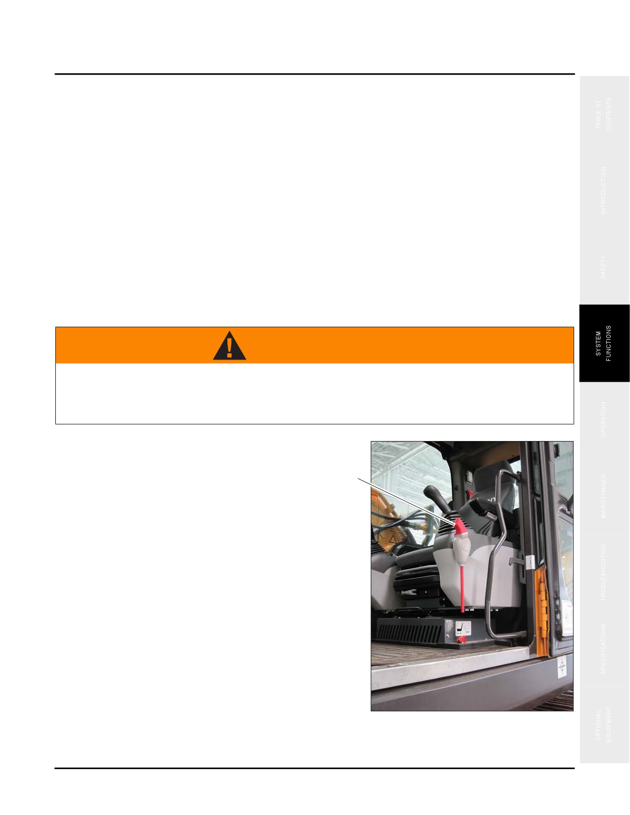
Hydraulic Lockout Control
WARNING
Always place the hydraulic lockout control securely in the LOCK position before leaving the
operator cab. If the hydraulic lockout control is not in the LOCK position any unintended
touch of the control levers may cause serious injury or death. Take care not to touch either
joystick when you pull (up) or push (down) the lockout control.
The hydraulic lockout control (1) is a device used to lock
out the control levers of all work equipment to include the
swing system, travel system and optional attachments.
1
•
To engage the machine in the LOCK position push
down the hydraulic lockout control. The machine
will not move even if you maneuver the controls.
•
Pulling up the hydraulic control level places the
machine in the UNLOCKED position where the
machine moves in accordance with the joysticks
and other control levers.
Fig. 3-16
3-17
Cab Interior
SY335 Excavator
WARNING
If any part of the machine moves when the hydraulic lockout control is engaged, it indicates a
failure in your machine. In this case, immediately engage the hydraulic lockout control and
stop the engine. Contact your Sany distributor to solve this problem.
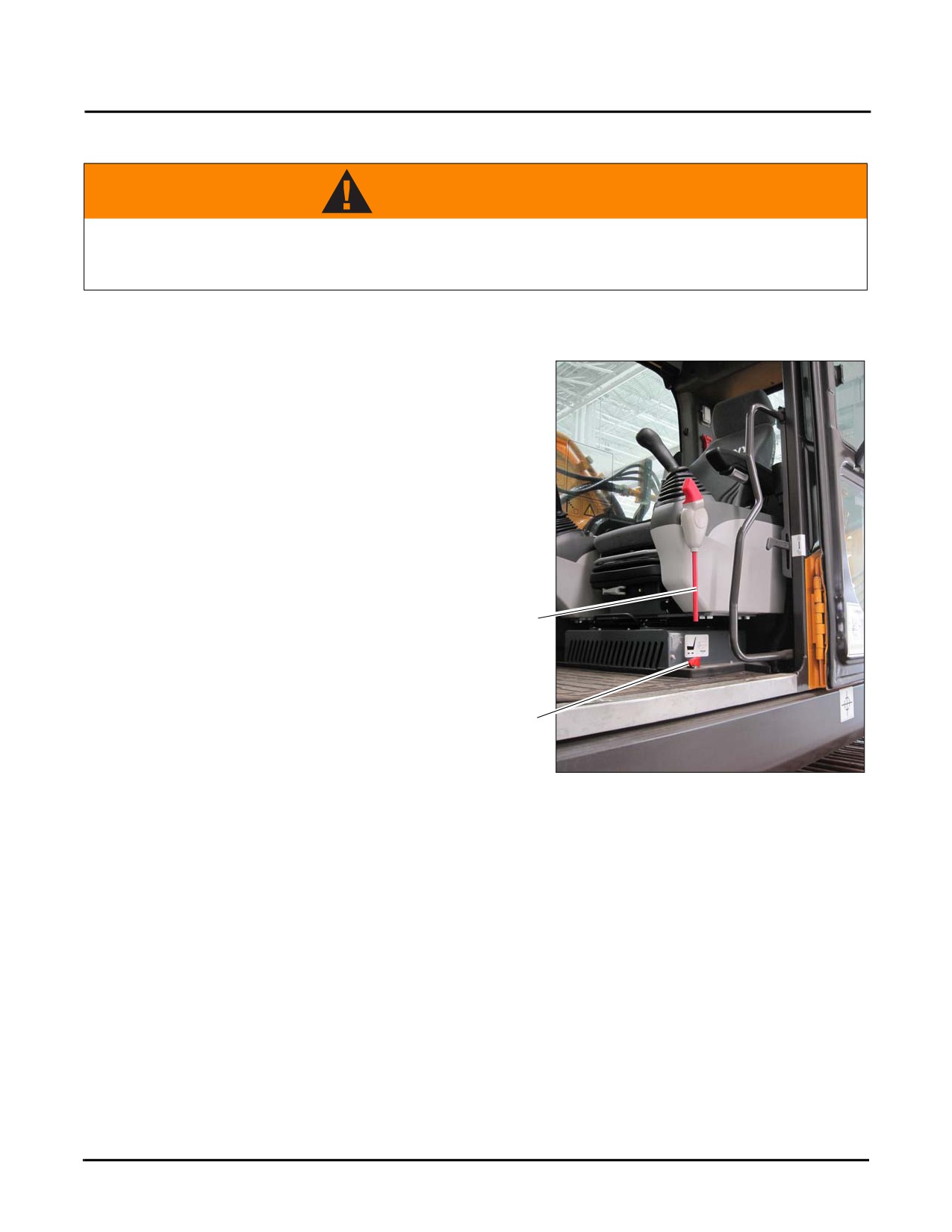
Emergency Stop Switch
The engine emergency stop switch (1), which is located just
below the hydraulic lockout control (2), is normally on
during regular operation of the excavator.
In case of an emergency, press the emergency stop switch
to shut down the engine. The hydraulic lockout control can
be used to lock out the hydraulic system while the engine
emergency stop switch (1) is used to ensure the safety of
the engine.
2
1
Fig. 3-17
3-18
SY335 Excavator
Cab Interior
Joystick Controls
WARNING
Never expose any part of your body outside the window, this may put you in danger of being
hurt by the boom if the joystick is moved unexpectedly. If a window is broken or missing,
replace it immediately.Know the positions and functions of each joystick control. Unexpected
movement of the machine could cause personal injury or death!
There are two operating modes available for the joysticks;
the SAE (Society of Automotive Engineers) mode (see
page 3-19) and BHL (Back Hoe Loader) mode (see page 3-
19). To chose between these two modes follow these
instructions.
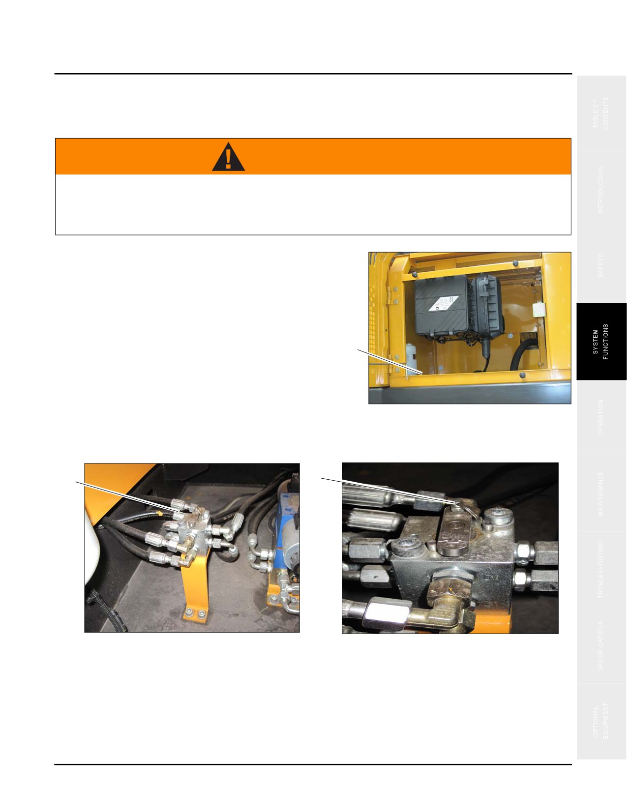
a
SAE/BHL Selector Switch
The SAE/BHL selector switch (a) is located below the
engine air cleaner inside the left side front cover.
Fig. 3-18
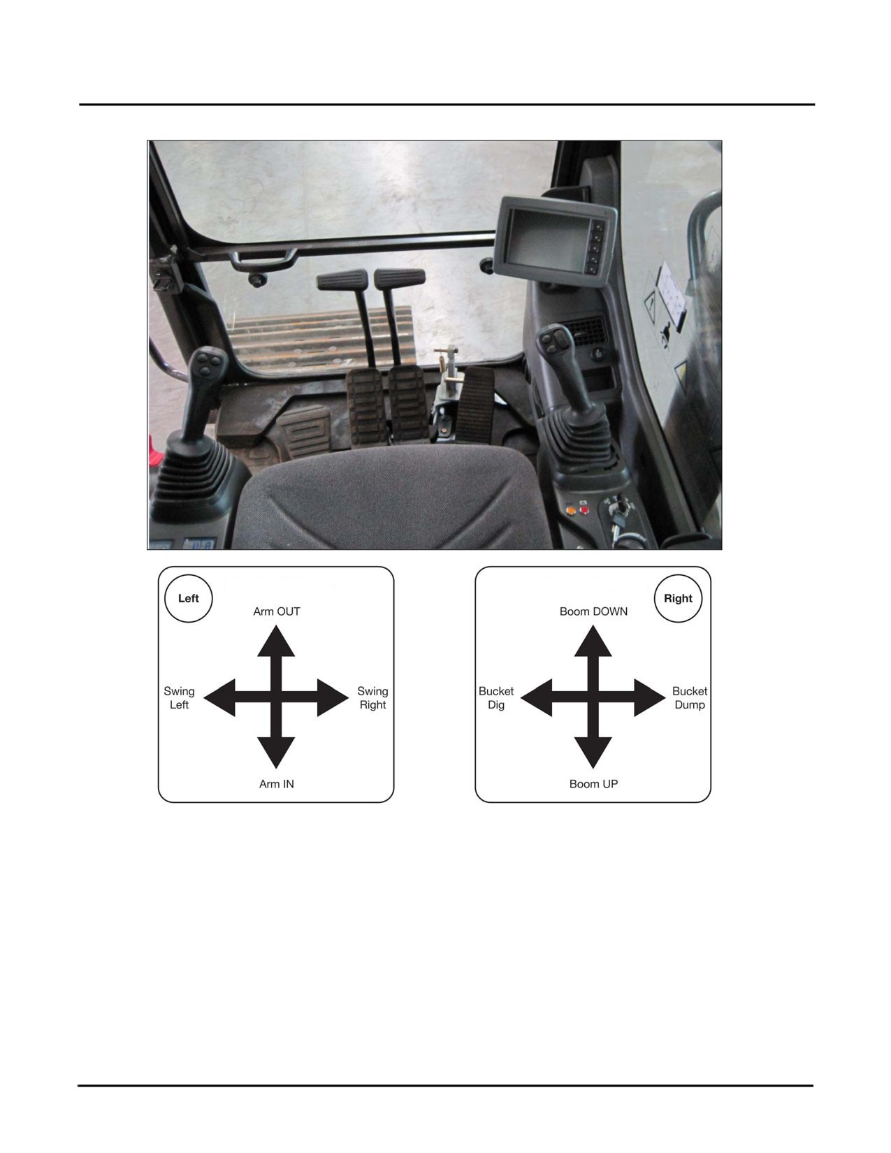
The SAE/BHL selector switch (b) swaps the control of the
boom and the arm from one joystick to the other. The position shown (b) is the SAE mode position. To change to
the BHL position pull the pin up (c) and rotate the bar to the left. Release the pin to lock the bar in place.
c
b
Fig. 3-19
•
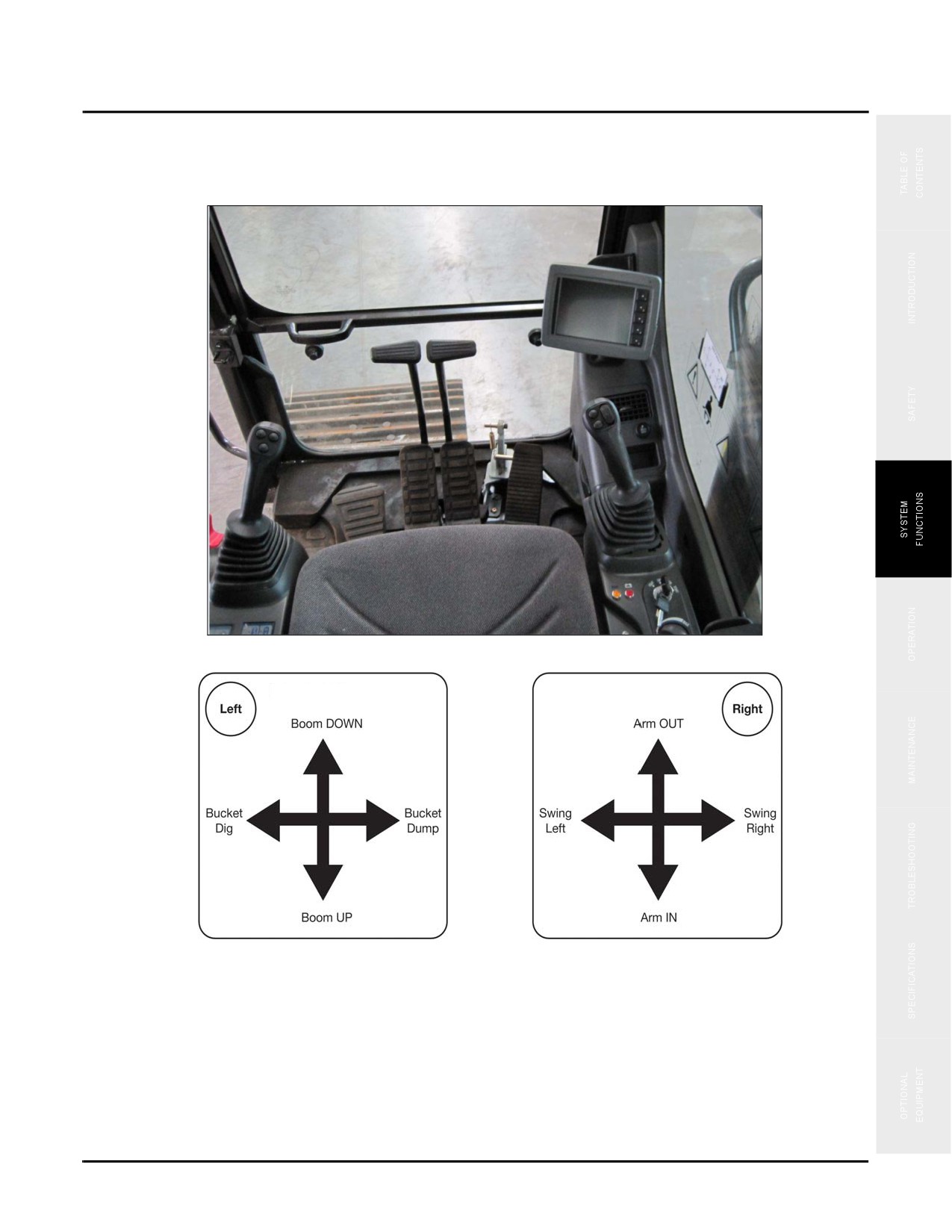
In SAE (Society of Automotive Engineers) mode, the arm is controlled using the left joystick and the
boom using the right joystick (see page 3-20).
•
In BHL (Back Hoe Loader) mode, the arm is controlled using the right joystick and the boom is controlled
using the left joystick (see page 3-21).
3-19
Cab Interior
SY335 Excavator
SAE Mode
Front
Front
Fig. 3-20
3-20
SY335 Excavator
Cab Interior
BHL Mode
Front
Front
Fig. 3-21
When travel control levers and joystick controls are in neutral, any maneuver of the control lever will set the engine
speed to go up to the speed set by the throttle. If travel control levers and joystick controls stay in neutral, engine
speed will decrease by 100 rpm. About four seconds later the engine will drop to the level (about 1,400 rpm) set for
automatic deceleration (see page 3-24).
Once you release the control lever or joystick, the machine goes back into neutral and the machine stops.
3-21
Cab Interior
SY335 Excavator
Joystick Switches
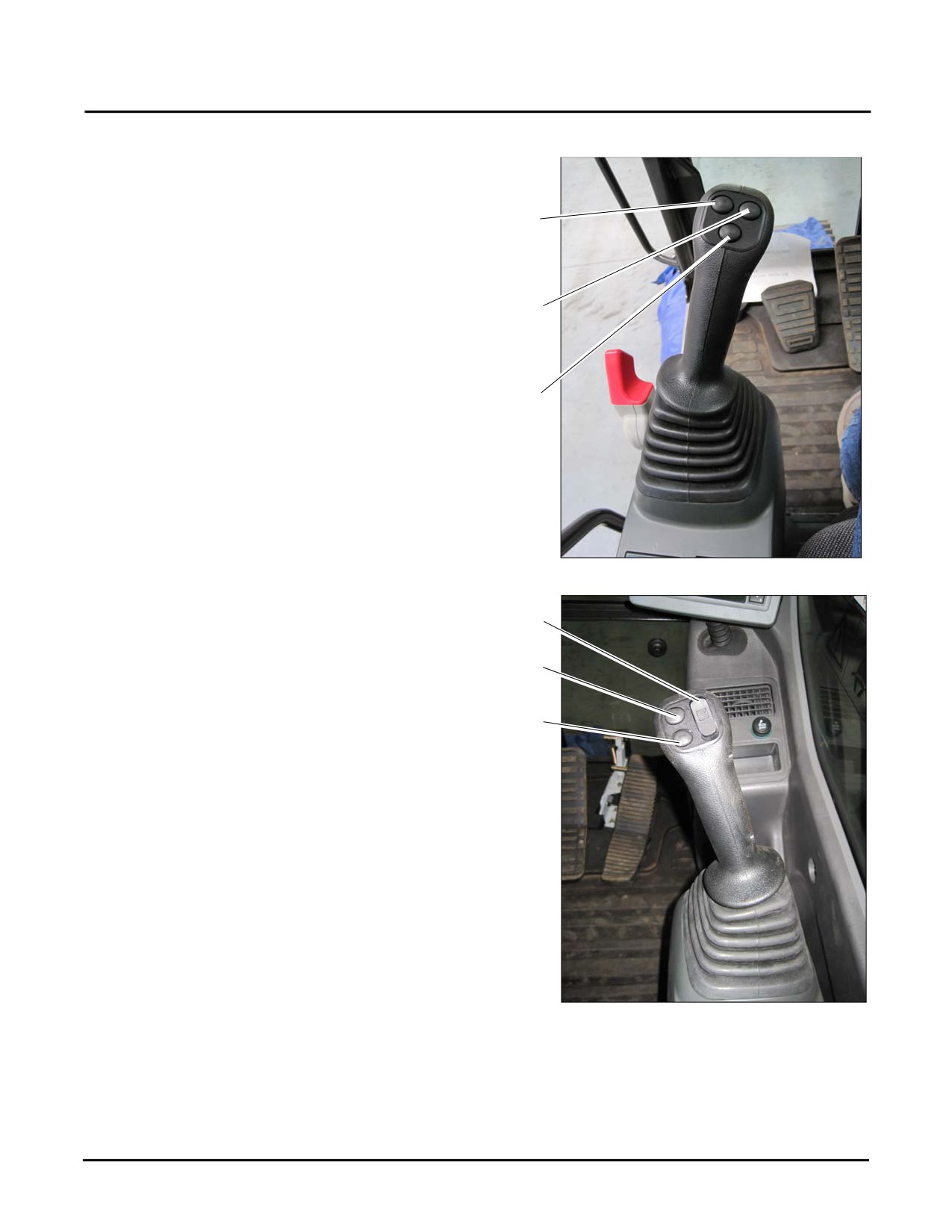
Left Joystick
1
The left joystick contains three buttons which are used to
control optional equipment:
•
Button 1 slews the optional equipment left
2
•
Button 2 slews optional equipment right
•
Button 3 optional equipment button; activated only
3
with the Nibbler and Breaker tools
Fig. 3-22
Right Joystick
4
The right joystick contains two buttons and a switch:
5
•
Switch
4 controls optional equipment which is
activated by sliding the switch back
(on) and
forward (off).
6
•
Button 5 activates the horn
•
Button 6 is the back-up horn.
Fig. 3-23
3-22
SY335 Excavator
Cab Interior
Travel Controls
WARNING
Take extra care when driving or steering the machine with pedals. Do not put your foot on any
pedal when they are not used.
1
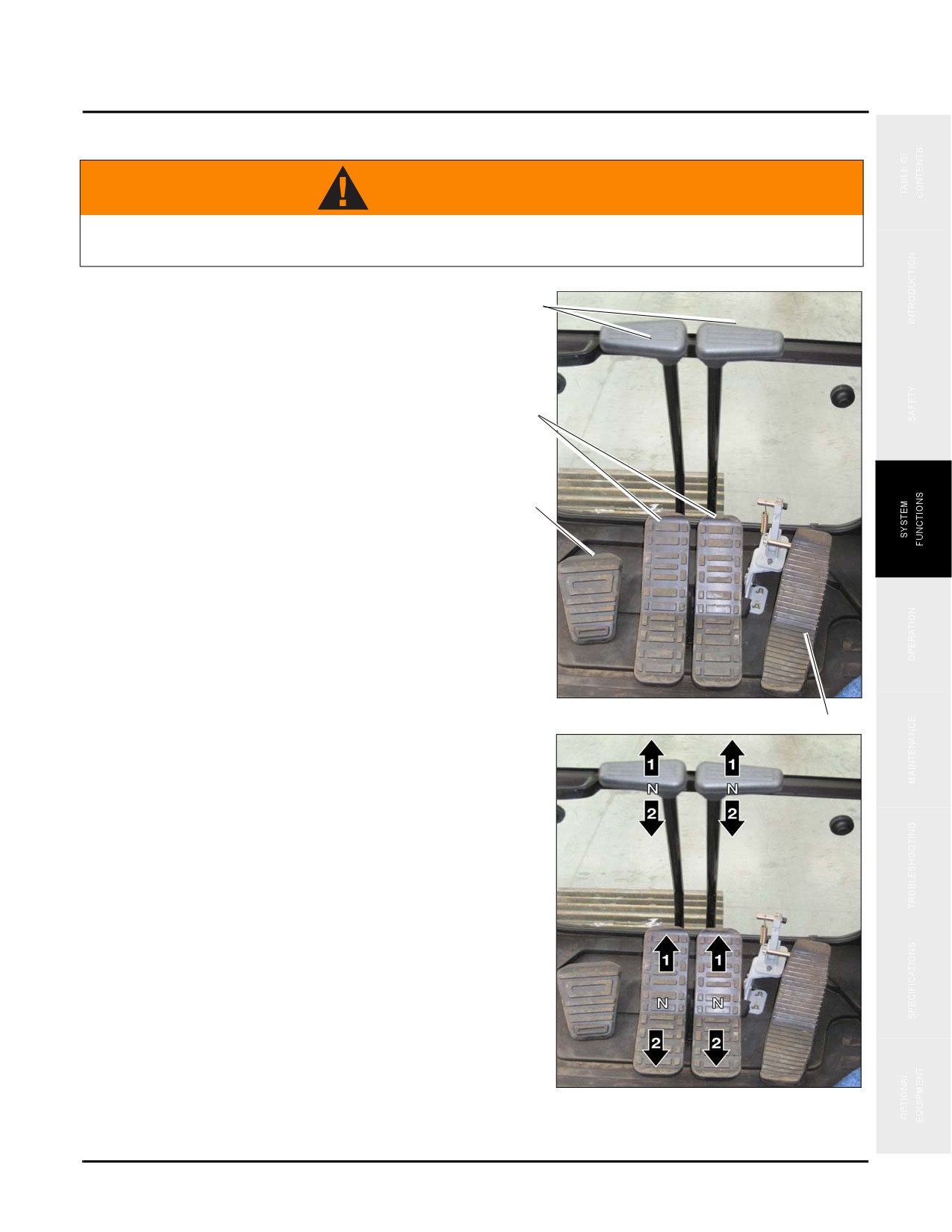
The machine Travel Controls group consists of the
following pedals:
1. Travel control levers
2
2. Travel control pedals
3. Foot rest
3
4. Auxiliary equipment control pedal
Fig. 3-24
4
The control levers/pedals are used to change travel direction
of your machine. The description in brackets is given for
pedal operation.
1. Forward travel:
Push the control lever (pedal tilts forward)
2. Backward travel:
Pull the control lever (pedal tilts backward)
3. N - (Neutral Position): Machine stops.
Fig. 3-25
3-23
Cab Interior
SY335 Excavator
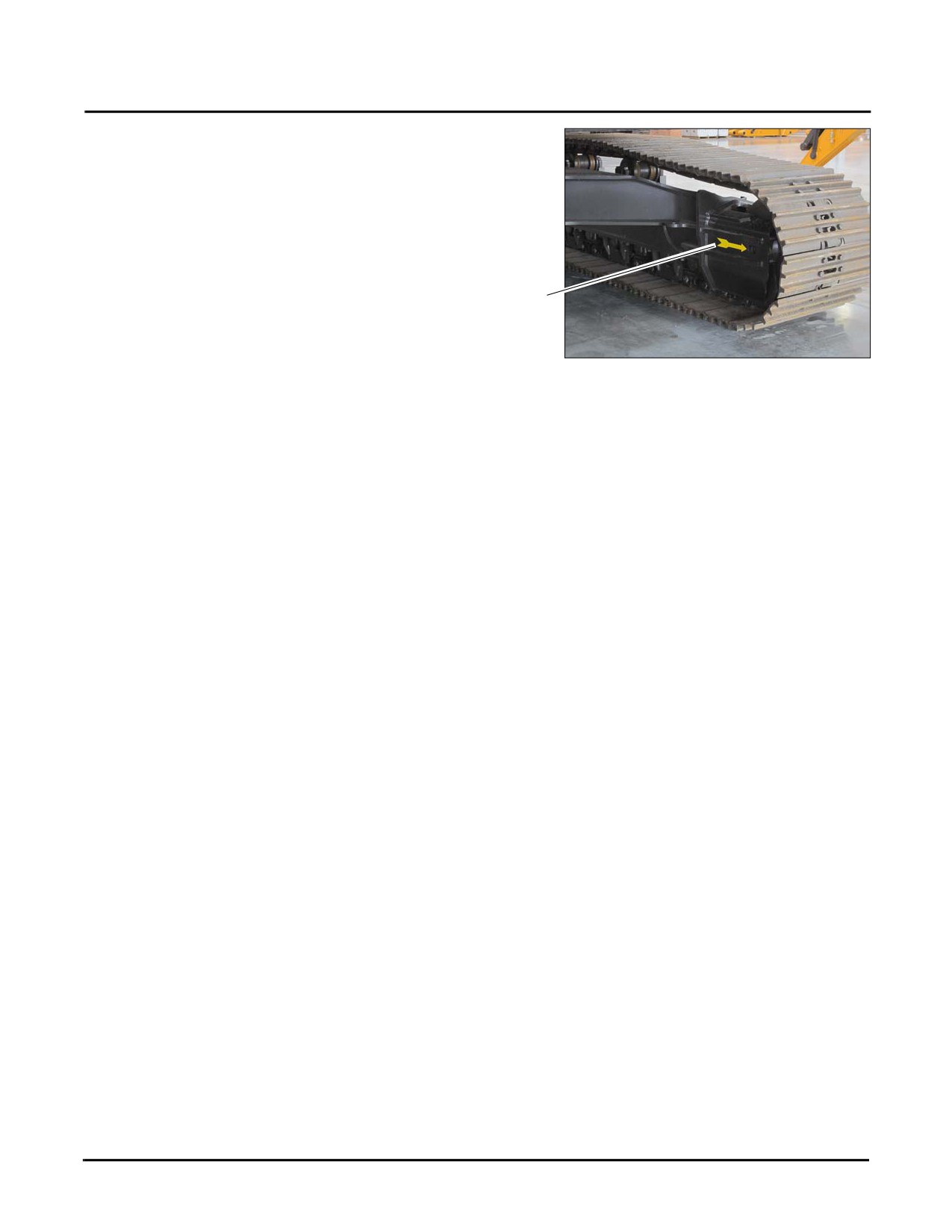
Always check the direction (4) of track frame before you
maneuver the travel control levers. (If the sprocket is in the
rear, the track frame faces the front.)
When the track frame faces backward remember that the
travel direction will be opposite to the maneuvering
direction of travel control lever. (Machine moves forward
4
when you pull control levers and backward when you push
them. The left and right directions are reversed too.)
Fig. 3-26
Automatic Deceleration Function
The automatic declaration mode is automatically activated when the machine is energized. When no control levers
are operated within 5 seconds with the engine running, engine speed drops to idle to cut fuel consumption and
reduce noise. When any of the control levers is operated or fuel control dial is adjusted while the engine is idling,
engine speed returns to previous level or the newly set level automatically. With the automatic deceleration
function the travel control levers can be used to change engine speed in the following way.
•
When travel control levers and joystick controls are in neutral position, engine speed will drop to medium
level even if fuel control dial is set above medium speed. If you maneuver any control, the engine speed
will rise to the level set on the throttle.
•
If travel control levers and joystick controls are in neutral the engine speed will decrease by 100 rpm.
About four seconds later engine will drop to the level (about 1,400 rpm) set for automatic deceleration.
3-24
SY335 Excavator
Cab Interior
Fuses and Batteries
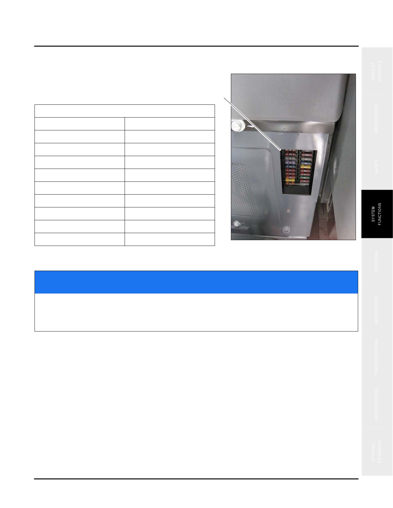
The fuse panel (1) is located at the left rear of operator's seat.
1
Fuse location, circuit & amperage
F2. Cab Lamp, 2A
F1. Horn, 5A
F4. Display, 10A
F3. Ignition circuit, 20A
F6. ECM, 30A
F5. 12V power supply, 10A
F8. Connector, 10A
F7. 24V power supply, 10A
F10. Dome lamp, 10A
F9. Boom light, 10A
F12. Air conditioner, 20A
F11. HCU controller, 15A
F14. Battery charge, 15A
F13. Radio, 3A
F16. Travel alarm, 2A
F15. Windshield washer, 2A
F18. Windshield Wiper, 10A
F17. Pilot Control, 10A
F20. Rear camera, 5A
F19. Emergency stop, 5A
Fig. 3-27
NOTICE
Before replacing a fuse, make sure that the start switch is in OFF position. Fuses should be
replaced if it is eroded, produces white powder or becomes loose in the fuse panel. Always
replace a fuse with one of the same capacity, never replace a fuse with one of a higher
capacity. Doing this may cause the machine to catch on fire.
3-25
Cab Interior
SY335 Excavator
Batteries and Power Disconnect Process
Battery
The machine uses a 24C DC electrical system, supplied by
two batteries connected in series and located inside the
vehicle as shown (1). The batteries (2) are used to start the
engine and supply power for the electric control cables and
lighting equipment.
1
Fig. 3-28
Power disconnect process
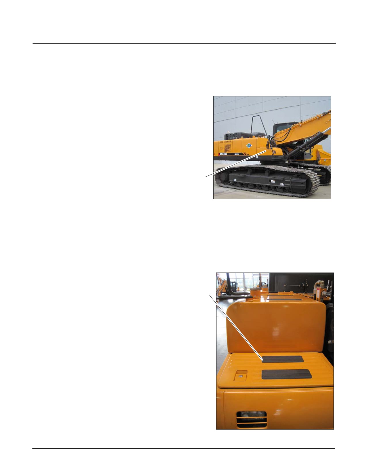
1. Locate and unlock the battery compartment access panel (a) on the left front side of the machine.
a
Fig. 3-29
3-26
SY335 Excavator
Cab Interior
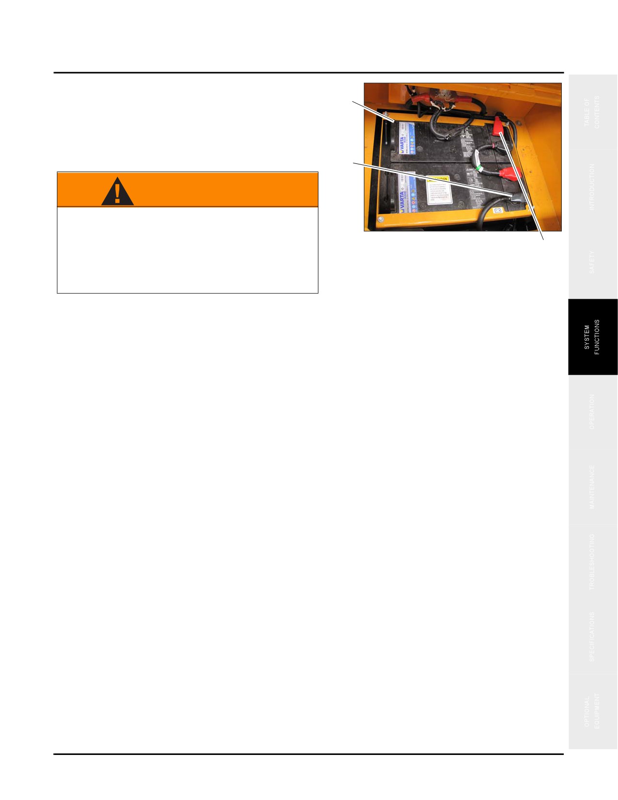
2. Open the battery compartment access panel to view the
batteries
(b).To disconnect power from the machine
b
remove the black (ground) cable (c) from the battery
terminal first, then remove the red (power) cable (d)
from the battery terminal second.
c
WARNING
When working with any open electrical power
source ensure that your hands are free of any
Fig. 3-30
metal objects
(rings, watches, jewelry) that
d
could come in contact with electrical power
points. Failure to do so could cause personal
injury or electrical shock.
3. To reconnect power, reverse the process shown in step 2 insuring that the red cable is connected first followed by
the black cable.
3-27
Combined Instruments Display/Monitor
SY335 Excavator
COMBINED INSTRUMENTS DISPLAY/MONITOR
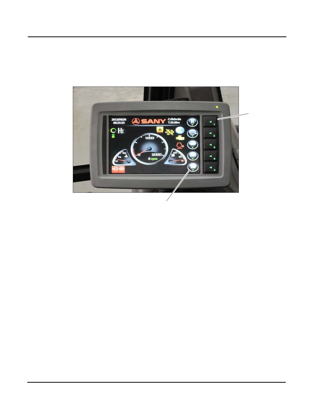
When the key switch of excavator is turned to the ON position, the Combined Instrument Display is energized by
the engine battery and initializes. A full display of the working Combined Instrument Display is shown below:
2
Fig. 3-31
1
Combined Instrument Display screen
The Combined Instrument Display shows the working mode selection and various elements of machine
performance.
•
Displaying running parameters
•
Viewing machine configuration
•
Viewing failure codes
•
Throttle (rpm)
•
Setting up system clock
•
Setting up service hours
•
Setting up key parameters
Additional details may be seen on the display by using the Function Icons (1) and the corresponding Function Keys
(2).
3-28
SY335 Excavator
Combined Instruments Display/Monitor
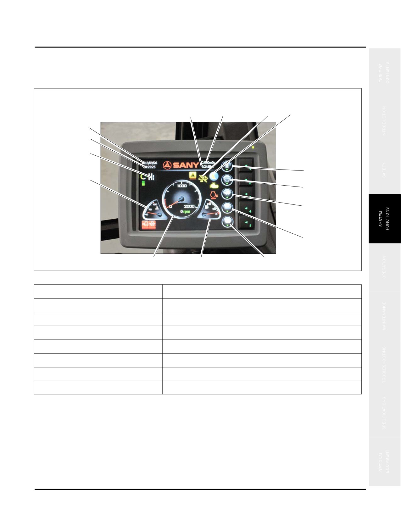
The Combined Instrument Display shows page heading, contents, parameters, time and function icons according to
the item selected. Options, values or parameters for the machine can be set-up as desired. Major information
elements are as follows:
15
14
13
12
1
2
3
11
4
10
9
8
5
6
7
Fig. 3-32
1. Local date (year/month/day)
9. Travel speed (high/low): Lo → Hi → Lo.
2. Local time (hour/minute/second)
10. Auto Deceleration function - Off/On
3. Working mode (S, H, L or B)
11. Change working mode: H → S → L → B → H.
4. Coolant temperature
12. Tool selected (Bucket - Breaker - Nibbler)
5. Tachometer
13. Regeneration symbol (shows regeneration disabled)
6. Fuel gauge
14. Current service hours
7. Next page
15. Total service hours
8. Backup camera
3-29
Combined Instruments Display/Monitor
SY335 Excavator
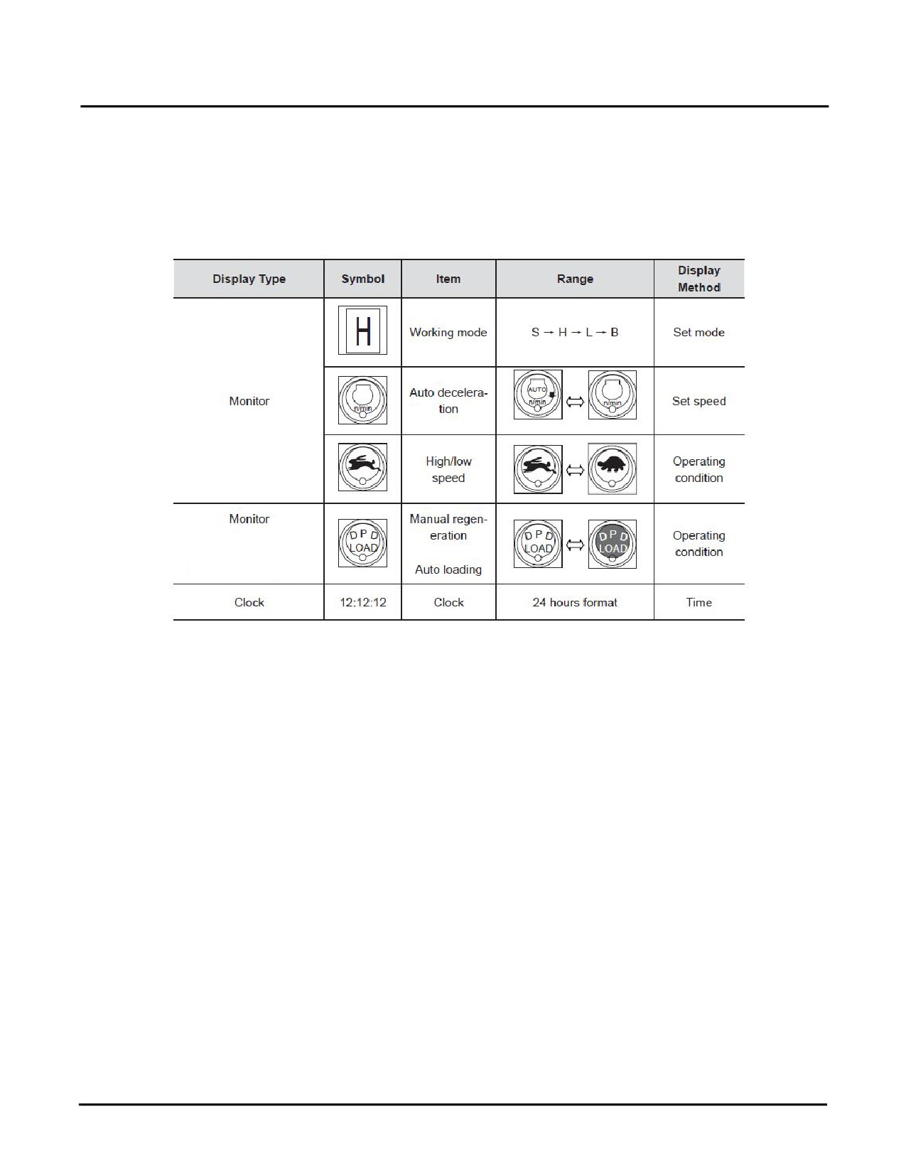
This is the default operating condition after the machine is powered on:
•
Working mode: S
•
Full speed/auto deceleration: Auto deceleration
•
Travel speed (high/low): Low
Fig. 3-33
3-30
SY335 Excavator
Combined Instruments Display/Monitor
Function Icons
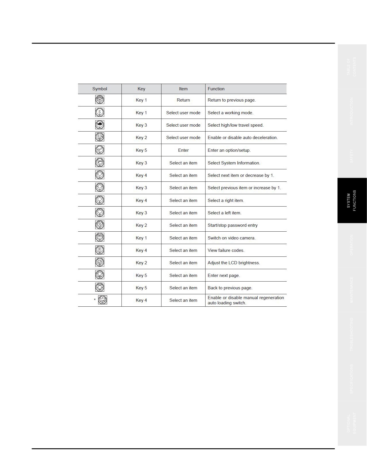
Function icons for corresponding keys and functions are given in the table below:
Fig. 3-34
Function Keys
The function keys are used to change a screen page, select an item and modify a value. Details are provided in
separate descriptions on the following pages.
System Information
Enter the password before accessing the system information page.
NOTE: If you do not know the password contact your supervisor.
3-31

Combined Instruments Display/Monitor
SY335 Excavator
1
2
3
4
5
1. Enter your 5-digit password. Each digit is indicated by an asterisk (*) standing for a value from 0 to 9. A
numeral appears at the digit where the cursor is located while the other four digits remains as asterisks.
2. Pressing Key 2 switches between Left-Right function and increase/decrease function.
3. Pressing Key 1 goes back to previous page.
Use the function keys to:
•
Key 1: Back to previous page.
•
Key 2: Start or stop setting up the code number on digit where the cursor is located.
•
Key 3: Decrease a value or move the cursor to the left digit.
•
Key 4: Increase a value or move the cursor to the right digit.
•
Key 5: Check the validity of password entered. If it is valid, you have access to the Main Menu.
3-32
SY335 Excavator
Combined Instruments Display/Monitor
Main Menu Functions
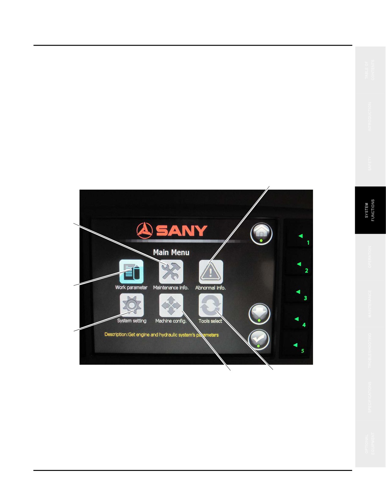
Once you enter the password you should go to the Main Menu. These are a list of system functions that can be
accessed by selecting an item and then entering the corresponding page. Each icon will be highlighted as you chose
them.
1. Parameter - view the running parameters of the engine and hydraulic system
2. Maintenance - view maintenance information on the excavator
3. Fault info (Error codes)
4. Work Equip (Bucket- Breaker - Shear)
5. Config - configure the machine and view configuration of the excavator
6. System Setup - language selection
3
2
1
6
Fig. 3-35
5
4
7. To select each icon press Key 4
8. To select a previous icon press Key 1
9. To approve the selection press Key 5
3-33
Combined Instruments Display/Monitor
SY335 Excavator
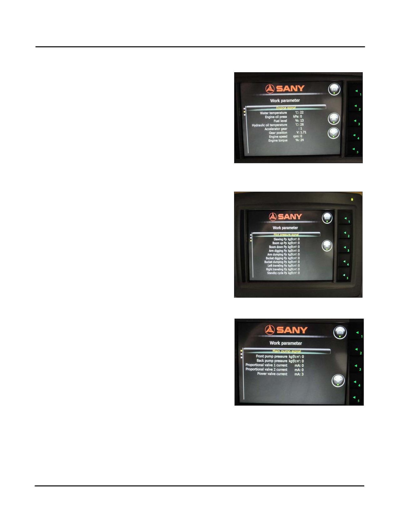
Engine and Throttle Signals
Engine running parameters are displayed as shown.
•
Press Key 4 to view pilot pressure signals.
•
Press Key 3 to view main pump signals.
•
Press Key 1 to return to the Main Menu.
Fig. 3-36
Pilot (Hydraulic Control) Pressure Signals
Pilot (Hydraulic Control) pressure signals are displayed as
shown.
•
Press Key 3 to view engine signals.
•
Press Key 1 to return to the Main Menu.
Main Pump Signals
Fig. 3-37
Main pump signals are displayed as shown.
•
Press Key 4 to view engine signals.
•
Press Key 1 to return to the Main Menu.
Fig. 3-38
3-34
SY335 Excavator
Combined Instruments Display/Monitor
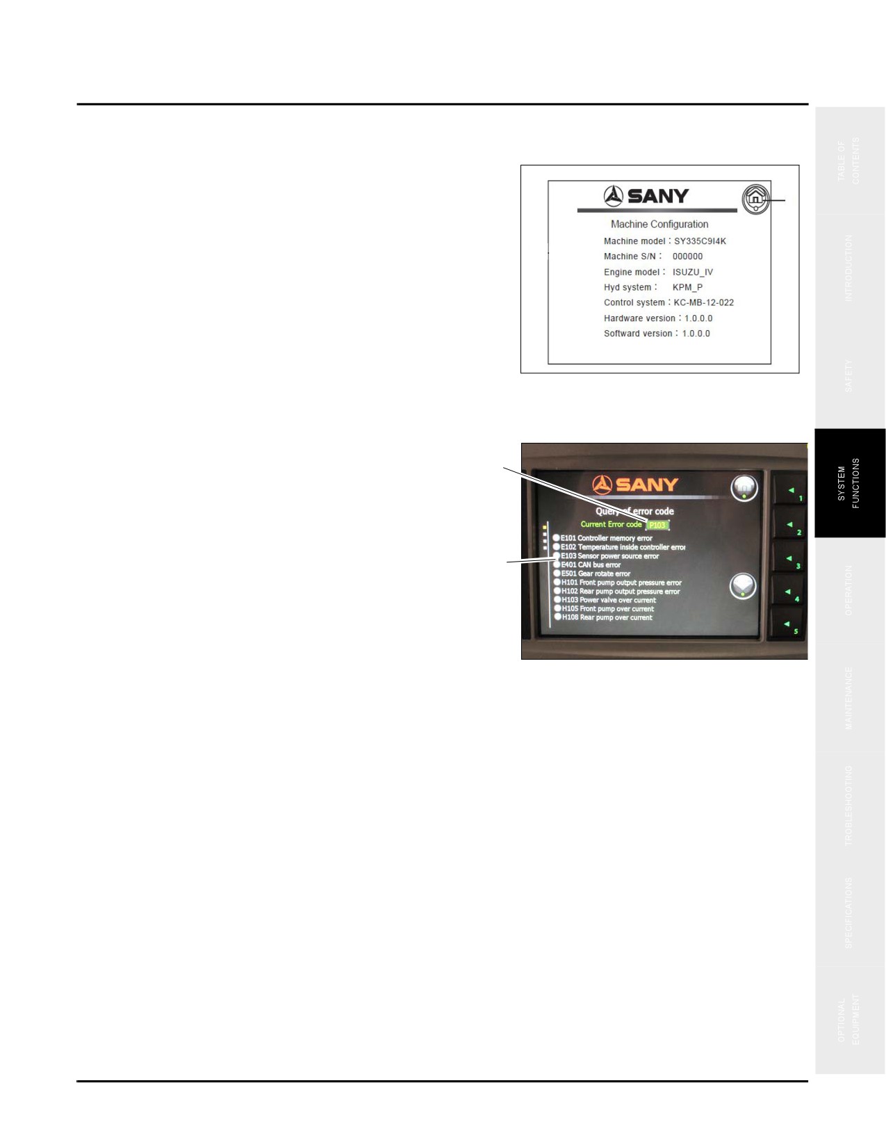
Machine Configuration
Information on key components of the machine is
displayed as shown.
1
•
Press Key 1 to view return to the Main Menu.
Fig. 3-39
Fault Information
Error codes and explanation are displayed as shown.
1
1. Failure code.
2. Failure code explanations.
2
•
To return to the home page press Key 1.
Fig. 3-40
3-35
Combined Instruments Display/Monitor
SY335 Excavator
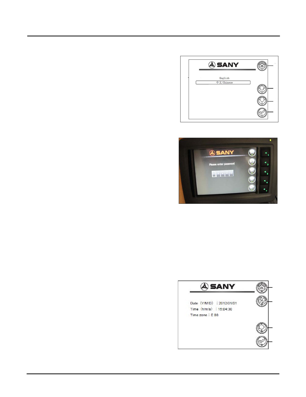
System Language Selection
How to select a language for the system.
1
1. Display of language options.
•
Press Key 1 to return the Main Menu.
3
•
Press Key 3 to scroll up the list.
4
•
Press Key 4 to scroll down the list.
5
•
Press Key 5 to accept the language selected.
Fig. 3-41
Machine Configuration Setup
To set up the serial number of the machine.
1. Press Key 1 to enter system setup.
2. Press Key 2 to:
•
(a) choose the digit where the number goes
•
(b) accept the number selected
Fig. 3-42
3. Press Key 3 to move the cursor to a right digit to locate
a number.
4. Press Key 4 to move the cursor to a left digit to locate a number.
5. Press Key 5 to accept the serial number entered and return to System Setup.
Time Setup
To modify the date and time.
1
1. Press Key 2 to start/stop modifying the value of digit at
where the cursor is located.
2
2. Press Key 4 to switch between the increase/ decrease
keys and left-right keys.
4
Use the function keys to:
•
Key 1: Back to previous page.
5
•
Key 5: Accept time setup and return to previous
Fig. 3-43
page.
3-36
SY335 Excavator
Combined Instruments Display/Monitor
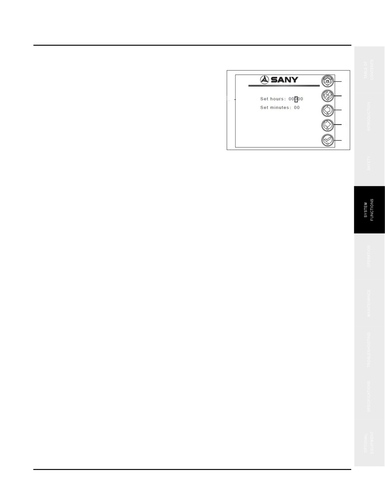
Service Hours Setup
To monitor service hours.
1
•
Press Key 5 to accept your setup.
2
•
Press Key 4 to move the cursor to the right.
3
•
Press Key 3 to move the cursor to the left.
4
•
Press Key 2 to start/stop setting up the number
5
where the cursor is located.
Fig. 3-44
•
Press Key 1 to return to System Setup.
3-37
Combined Instruments Display/Monitor
SY335 Excavator
This Page Intentionally Left Blank
3-38
SY335 Excavator
Operation
Operation
Work Area
4-3
General Job Safety
4-3
Job Site Safety
4-5
Work Crew
4-6
Supervisor
4-6
Owner and Other Authorized Personnel
4-6
Machine Operator
4-7
New Machine Run-In
4-9
Mount and Dismount the Machine
4-10
Pre-Start Checks
4-12
Daily Maintenance Record
4-12
Fuel Level
4-13
Draining Primary Fuel Filter
4-14
Hydraulic Oil Level
4-15
Engine Oil Level
4-16
SAE/BHL Selector Switch
4-17
Engine Coolant Level
4-19
Cab
4-20
Safety, Operation and Maintenance Manual
4-20
Seat, Seat Belt, Mirrors and Backup Camera
4-20
Work Lights and Warning Devices
4-22
Operator Controls
4-23
Fire Extinguisher & Escape Tool
4-23
Combined Instruments Display/Monitor Settings
4-24
Set Language Display - First Time
4-24
Set Date/Time Setting - First Time
4-27
Engine Procedures
4-29
Cold Weather Operation
4-29
Engine Start Procedure
4-30
Idle the Engine
4-32
Engine Shutdown
4-32
Travel Operations
4-34
Preheat the Machine
4-34
Safety, Operation & Maintenance Manual — November 28,
2013
4-1