SANY Excavator SY335 (Part Number: 11282013). Safety, Operation & Maintenance Manual - page 6
Daily Maintenance
SY335 Excavator
•
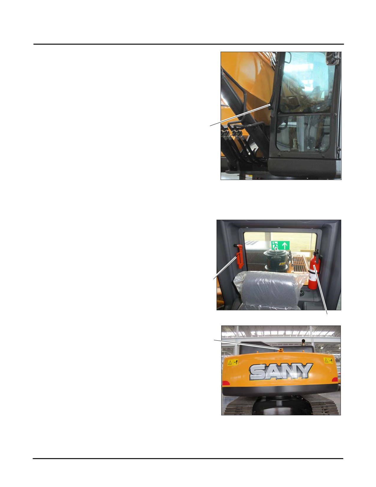
Windshield wiper and washer (5)
5
Fig. 5-10
Fire Extinguisher and Escape Tool
Check to be sure the fire extinguisher (1) is installed on the
machine and in proper working order. Follow the
instructions on the extinguisher to test the operation and
condition.
Check to be sure the escape tool (2) is installed on the
machine.
NOTE: See “Extinguisher and First Aid Kit” on
2
page 2-14.
Fig. 5-11
Typical
1
Backup Camera
1
Check and ensure that the backup camera is operational and
that the camera (1) itself is free of all obstructions and
debris.
NOTE: See
“Backup Camera” on page 4-22 for
additional information.
Fig. 5-12
5-18
SY335 Excavator
Daily Maintenance
Engine Oil Level
NOTE: See “Engine Oil Level” on page 4-16 for information on checking the oil level.
5-19
Daily Maintenance
SY335 Excavator
Pump Mounting Bolts
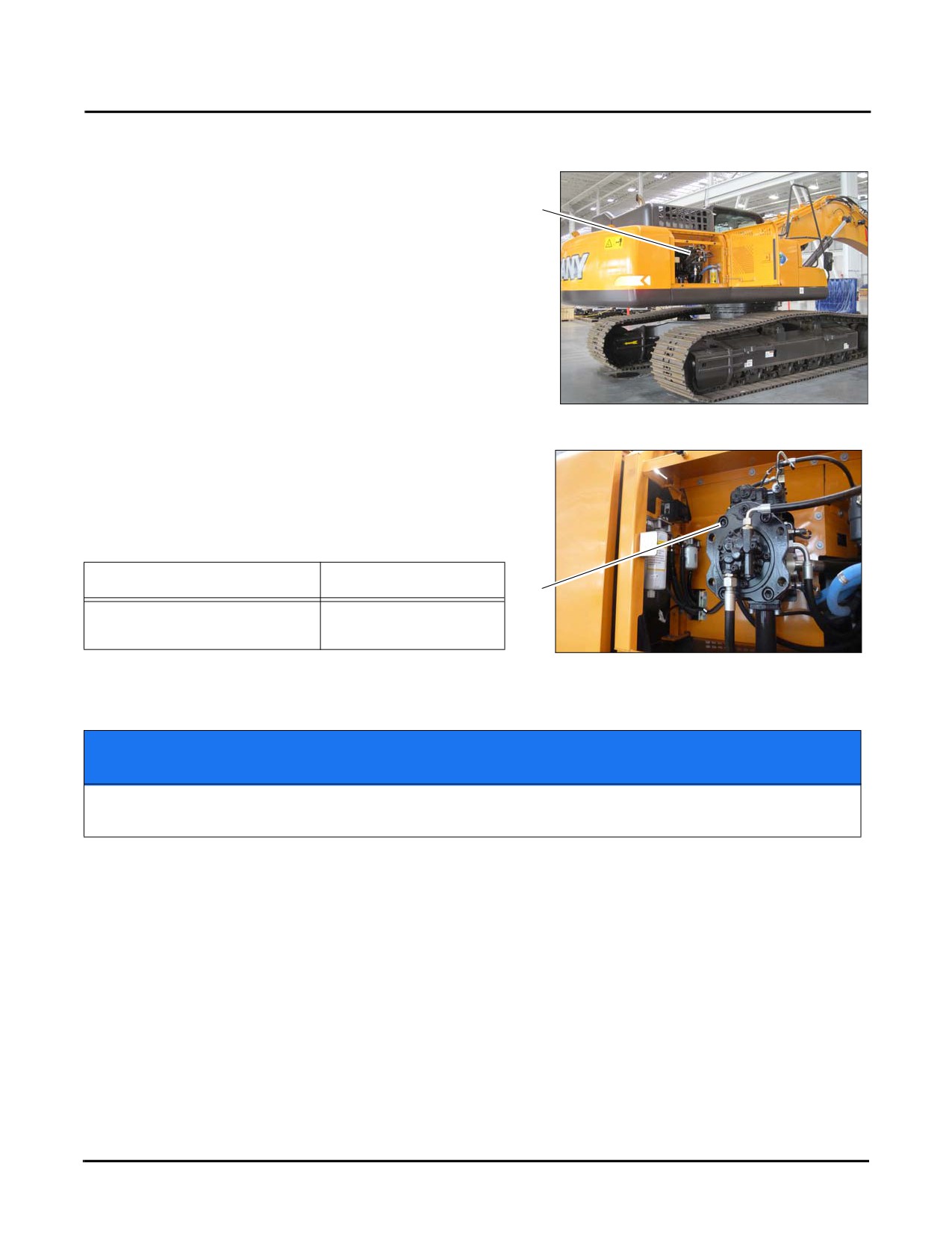
1. Locate and inspect the Hydraulic Pump (a) for loose,
broken or missing pump mounting bolts (b), and leaks or
a
cracking at these mounting bolt locations.
Fig. 5-13
NOTE: Not all pump mounting bolts are shown here.
Be sure to inspect all pump mounting bolt
locations.
2. Use the following table when tightening these bolts.
Bolt Type
Torque Value
b
Pump Mounting Bolt (M10×35)
36 ft•lb (49 N•m)
10.9
Fig. 5-14
NOTE: Contact your Sany distributor if any
abnormality is found.
NOTICE
Do not overtighten the mounting bolts. Failure to observe and follow this directive may result
in damage to the bolts, the mounting brackets or the engine case.
5-20
SY335 Excavator
Daily Maintenance
Fuel Level
NOTE: To check the Fuel Level See “Fuel Level” on page 4-13, see also “Fluids & Lubricants” on page 5-11.
Engine Coolant Level
Cummins® engine cooling system general recommendations are listed below. These recommendations apply to
both standard service intervals and extended service intervals. For an engine using standard service interval
coolant, the additive and glycol levels must be tested every 6 months.
Standard Maintenance
•
A small amount of coolant can leak when servicing the coolant filter (if equipped) with the shutoff valve in the
OFF position. Avoid contact with hot coolant to reduce the possibility of personal injury. Always allow
sufficient time for the engine to cool down to outdoor temperatures before servicing the cooling system.
WARNING
Coolant is toxic. Keep it away from children and pets.
NOTICE
If not re-used, dispose of the coolant in accordance with local environmental regulations.
Failure to do so may result in fines or punishment.
•
Fill up and top off cooling systems using a fully formulated coolant which meets Cummins®® Engineering
Standard 14603. Replace the coolant filter(s) at every recommended coolant filter change interval.
CAUTION
Do not remove the filler cap while the engine is hot. Engine coolant is under pressure when
hot and will spurt out. Always wait for the engine to cool to outdoor ambient temperatures
before removing the filler cap. Failure to follow this warning could result in minor or major
injuries.
NOTE: See “Engine Coolant Level” on page 4-19 for information on checking the Engine Coolant Level, see
also “Fluids & Lubricants” on page 5-11 for further information on coolant type.
5-21
Daily Maintenance
SY335 Excavator
Engine Serpentine Belt
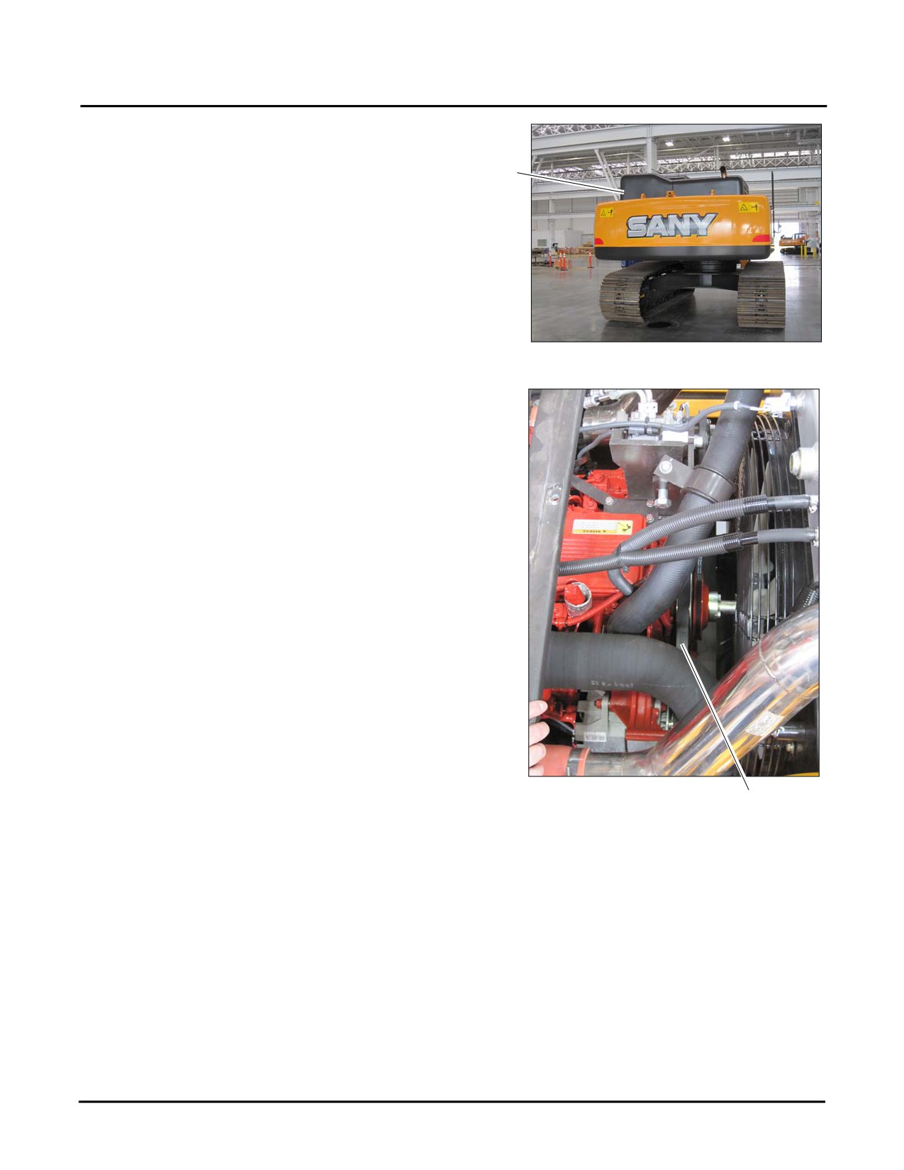
1. Unlock and open the engine hood (a).
a
Fig. 5-15
2. Locate the engine serpentine belt (b) and inspect the
belt for those items listed in step 3.
Fig. 5-16
b
5-22
SY335 Excavator
Daily Maintenance
3.
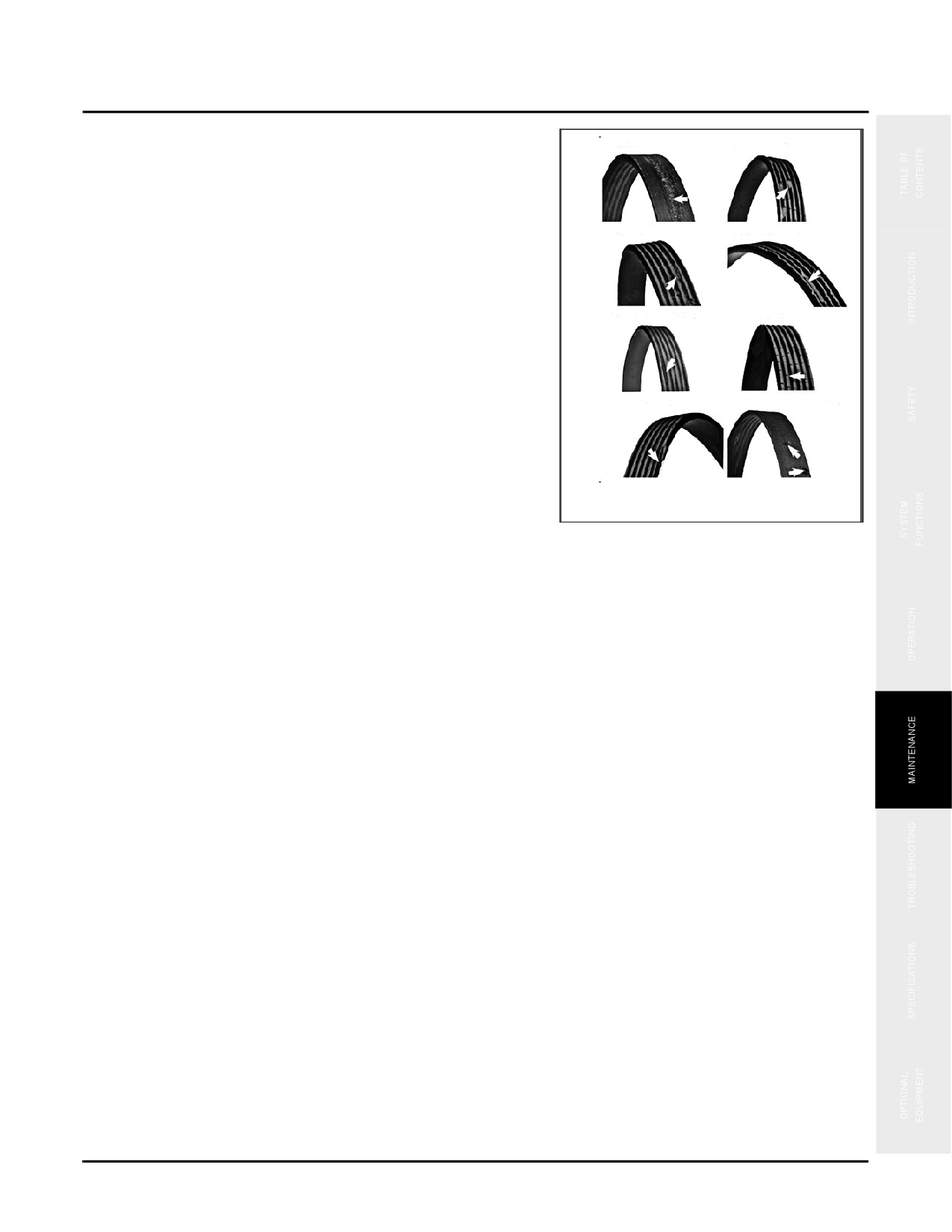
Compare the information here with the actual belt.
a. Abrasion: The belt appears shiny, glazed or fabric
is exposed. This is a sign that the belt is in contact
a
b
with an object such as a flange or bolt.
b. Chunk-out: Chunks of rubber material have
broken off from the belt. At this stage, the belt can
fail at any moment. Heat, age and stress are the
c
d
primary contributors.
c. Pulling: Belt material is sheared off from the ribs.
Lack of tension, misalignment, worn pulleys or a
f
e
combination of these are factors.
d. Uneven rib wear: Belt shows damage to the side
with the possibility of breaks in the tensile cord or
jagged-edged ribs. A thumping/grinding noise may
g
h
also be heard when running.
Fig. 5-17
e. Improper installation: A belt rib begins
separating from the strands. If left unattended, the
cover will often separate, causing the belt to
unravel.
f. Cracking: Small visible cracks along the length of a rib or ribs. With continuous exposure to high
temperatures, the stress of bending around the pulley leads to cracking.
g. Misalignment: Sidewalls of the belt may appear glazed or the edge-cord may become frayed. A
noticeable noise may result.
h. Gravel penetration: Small pinholes are visible on the backside of the belt. Bumps may be visible and
fabric around the holes can be frayed, indicating damage from foreign objects such as dirt, gravel or
similar debris.
4.
Replace all damaged belts.
5-23
Daily Maintenance
SY335 Excavator
Slewing Gearbox
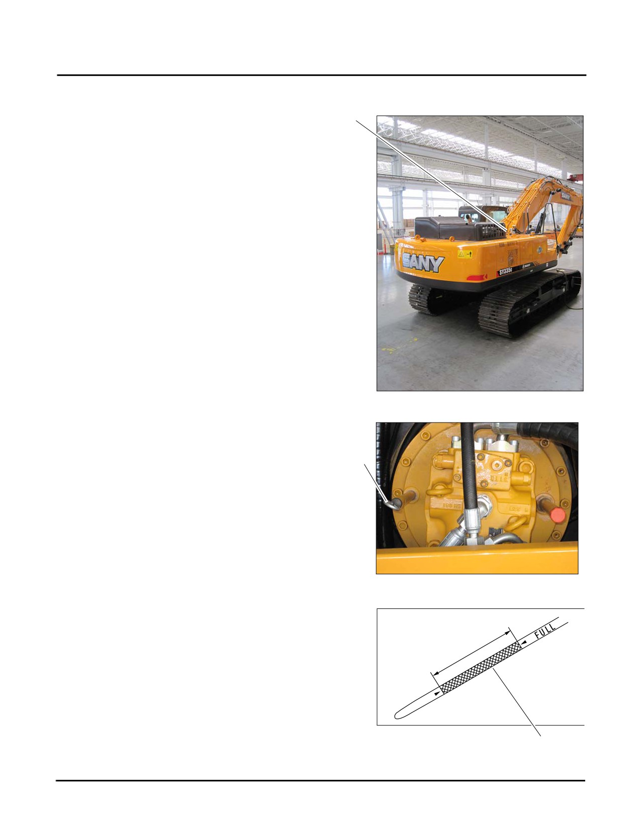
1. Locate and inspect the slewing gearbox (a) for physical
a
damage of any kind. Contact your Sany representative
for further advice if any damage is found.
Fig. 5-18
2. Remove the dipstick (b) from the slewing gearbox and
note the oil level on the dipstick.
b
Fig. 5-19
3. The oil level should be within the etched area (c) on the
dip stick surface.
Fig. 5-20
c
5-24
SY335 Excavator
Daily Maintenance
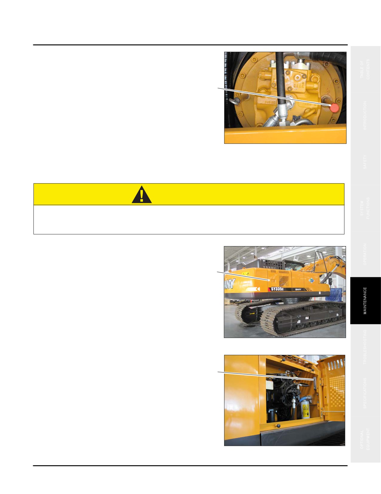
4. If necessary, remove the oil filler cap (d), add oil as
needed, then reinstall the cap. See
“Fluids &
Lubricants” on page 5-11
d
Fig. 5-21
Hydraulic Oil Tank
CAUTION
Hydraulic oil is hot and under pressure. Always wait for the machine to cool down to below
160°F (71°C) before attempting to maintain the hydraulic oil system. Failure to do so could
result in minor or major injuries.
1. Open the right rear access panel to access the hydraulic
oil tank (a), then check it for leaks, exterior rust and
other damage.
a
Fig. 5-22
2. Check the oil level (b) via the sight glass on the side of
tank. Insure that the oil level is between the level marks
b
on the sight glass.
NOTE: See
“Hydraulic Oil/Ambient Temperature
Data” on page 5-13 for proper hydraulic oil.
NOTE: Do not add hydraulic oil to the tank if the
instrument display shows a reading higher
than 160°F (71°C)
Fig. 5-23
5-25
Daily Maintenance
SY335 Excavator
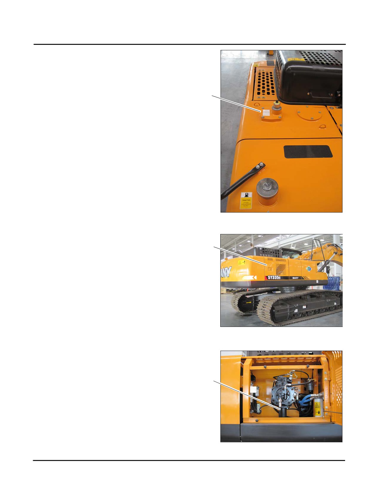
3. If necessary, remove the filler cover
(c) and add
hydraulic oil to the system until the hydraulic oil level is
between the level marks on the sight glass (b).
4. Check and tighten the various hydraulic fittings and/or
replace any that are defective, especially if the hydraulic
c
oil level has noticeably dropped since the previous level
check.
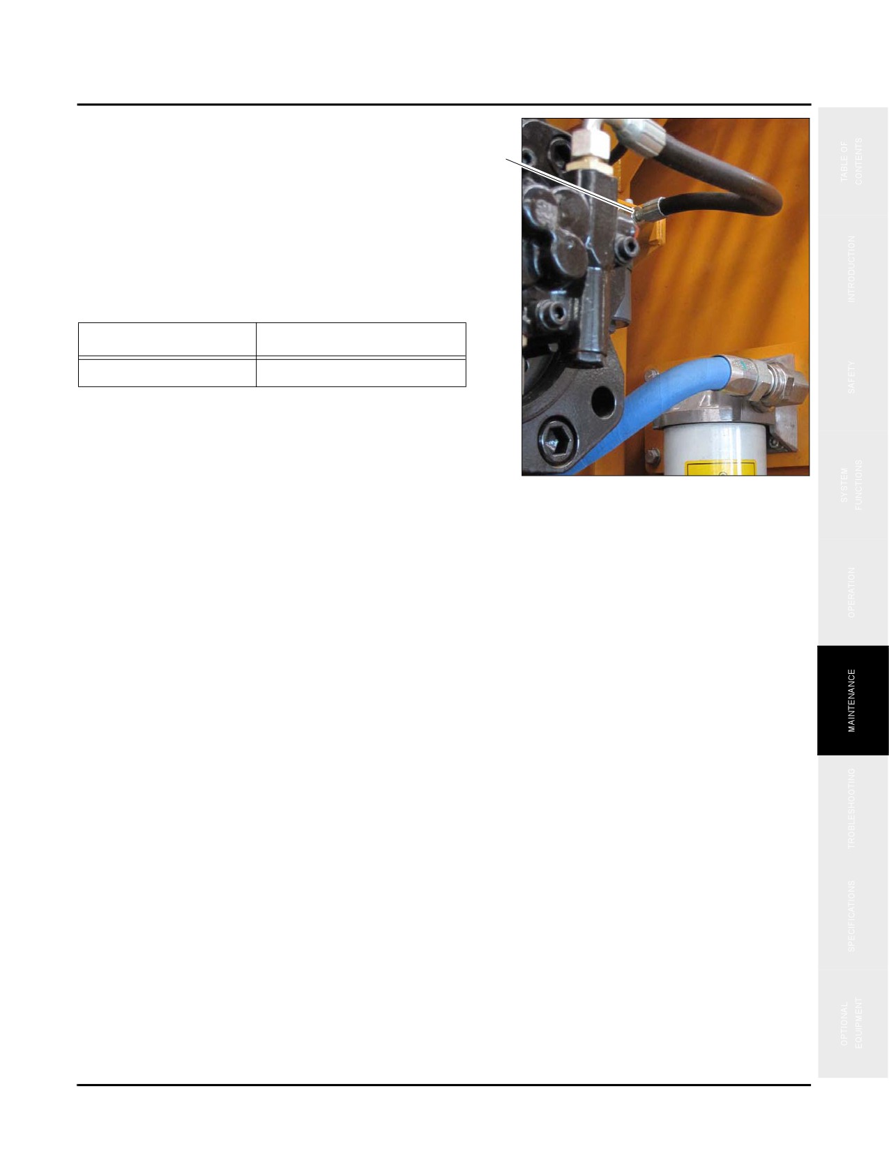
Hydraulic Line Connections
Fig. 5-24
1. Open the right rear access panel (a).
a
Fig. 5-25
2. Examine the hoses (b) between the tank and the hydraulic
pump for leaks, breaks or loose connections.
b
Fig. 5-26
5-26
SY335 Excavator
Daily Maintenance
3. Check fittings (c) at both ends of the flexible hose every
day. Be sure to inspect all bolt locations.
c
NOTE: These bolts/screws at each end of this hose may
loosen occasionally due to vibration. Leaks at
the angled seals will eventually result in pump
failure.
4. Replace any damaged or defective bolts and retighten
any loose bolts.
Bolt Diameter (Grade)
Torque Value
M16 (8.8
86-106 ft•lb (116-144 N•m)
NOTE: Do NOT use thread sealant when reinstalling
loose bolts and installing new bolts.
Fig. 5-27
5-27
Daily Maintenance
SY335 Excavator
Electrical System
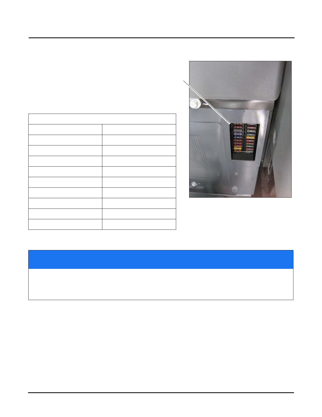
The electrical system should be inspected starting with the
box. The fuse box (a) is located at the left rear of operator's
seat. If a fuse is corroded or if a white powder can be seen on it,
a
contact your Sany distributor for repair information regarding
the electrical circuit in question.
Fuse location, circuit & amperage
F2. Cab Lamp, 2A
F1. Horn, 5A
F4. Display, 10A
F3. Ignition circuit, 20A
F6. ECM, 30A
F5. 12V power supply, 10A
F8. Connector, 10A
F7. 24V power supply, 10A
F10. Dome lamp, 10A
F9. Boom light, 10A
F12. Air conditioner, 20A
F11. HCU controller, 15A
F14. Battery charge, 15A
F13. Radio, 3A
Fig. 5-28
F16. Travel alarm, 2A
F15. Windshield washer, 2A
F18. Windshield Wiper, 10A
F17. Pilot Control, 10A
F20. Rear camera, 5A
F19. Emergency stop, 5A
NOTICE
Before replacing a fuse, make sure that the start switch is in OFF position and the battery is
disconnected. Fuses should be replaced if it is eroded, produces white powder or becomes
loose in the fuse panel. Always replace a fuse with one of the same capacity, never replace a
fuse with one of a higher capacity. Doing this may cause the machine to catch on fire.
5-28
SY335 Excavator
Daily Maintenance
Electrical power disconnect process
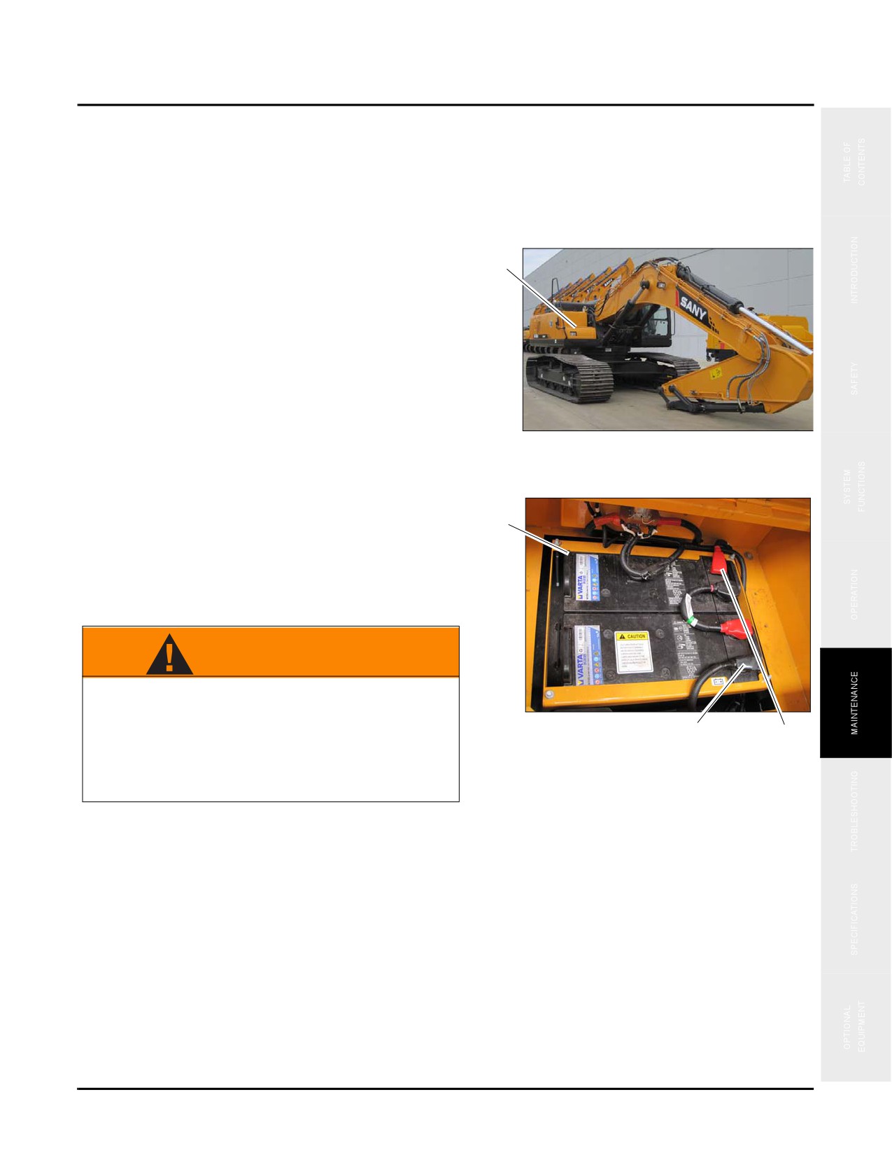
1. Locate and unlock the battery compartment access panel (a) on the right front side of the machine.
a
Fig. 5-29
2. Open the battery compartment access panel to view the
batteries
(b).To disconnect power from the machine
b
remove the black (ground) cable (c) from the battery
post first, then remove the red (power) cable (d) from
the battery post second.
WARNING
When working with any open electrical power
source ensure that your hands are free of any
Fig. 5-30
metal objects
(rings, watches, jewelry) that
c
d
could come in contact with electrical power
points. Failure to do so could cause personal
injury or electrical shock.
3. To reconnect power, reverse the process shown in step 2 insuring that the red cable is connected first followed by
the black cable.
Other electrical inspection points:
•
Inspect all electrical equipment and circuitry regularly; if necessary, remove and replace all faulty items,
including loose connectors, worn or degraded wiring, cables, etc.
•
Locate and remove the cause of any electrical faults.
•
Use only genuine spare parts and fuses as specified here.
•
Shut off the machine immediately if a fault occurs with the power supply.
5-29
Daily Maintenance
SY335 Excavator
•
Do not modify the electrical system without authorization.
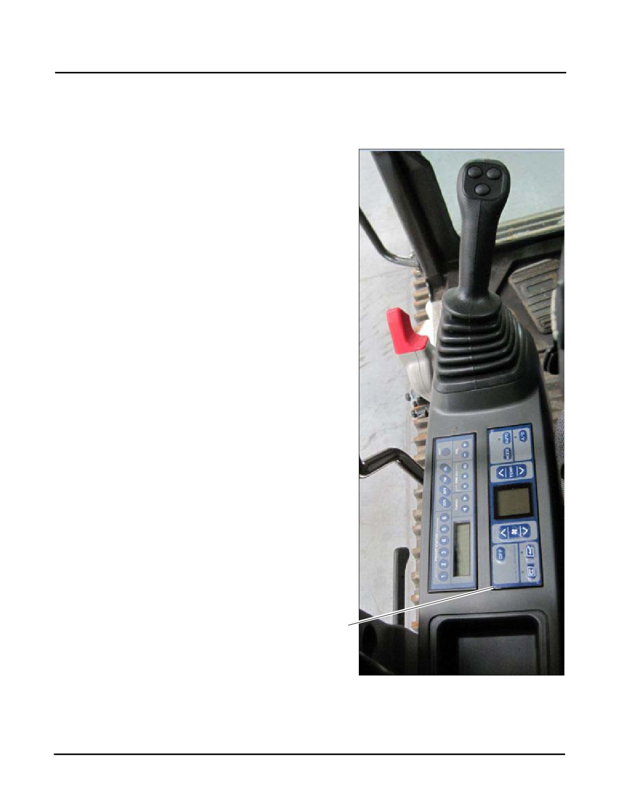
Air Conditioner
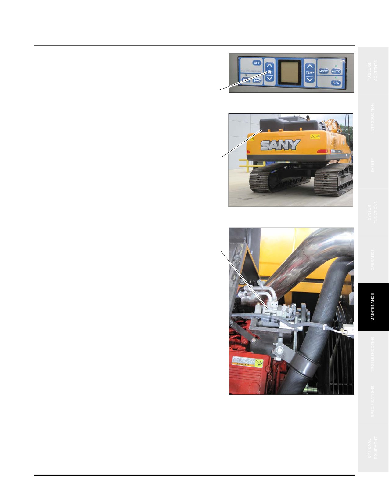
1. Engage the air conditioner control located (a) on the left console..
a
Fig. 5-31
5-30
SY335 Excavator
Daily Maintenance
2. Press the air conditioning fan switch (b) inside the cab
to check startup, air flow and fan speed control.
NOTE: To change temperature display from C° to F°
(or vice versa) press and hold the temperature
b
up/down arrows at the same time.
Fig. 5-32
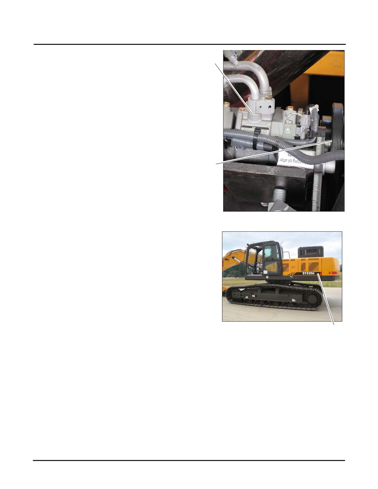
3. Go to the air conditioner compressor which is located
under the left engine hood (c).
c
Fig. 5-33
NOTE: The a/c compressor (d) is located above the
engine next to the exhaust pipe.
d
Fig. 5-34
5-31
Daily Maintenance
SY335 Excavator
4. Check for the following:
e
•
Refrigerant leakage at the pipeline connections (e)
•
Any blockage by debris
•
That the drive belt (g) is not loose, worn or twisted
g
Fig. 5-35
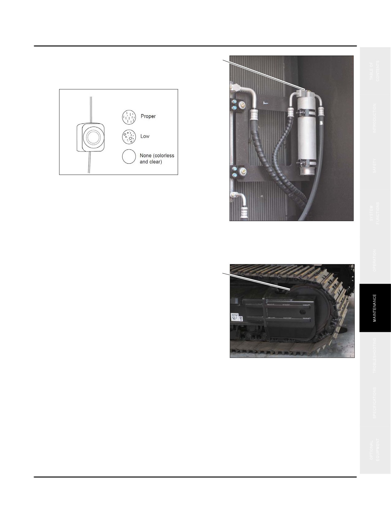
5. Open the left side rear access panel (h) to check the a/c
condensor.
Fig. 5-36
h
5-32
SY335 Excavator
Daily Maintenance
6. Check the sight glass on top of the condensor (k) for
k
refrigerant quantity.
Sight Glass
Fig. 5-37
Idler Wheel
Check the idler wheel (a) looking for cracks and distortion.
a
Fig. 5-38
5-33
Daily Maintenance
SY335 Excavator
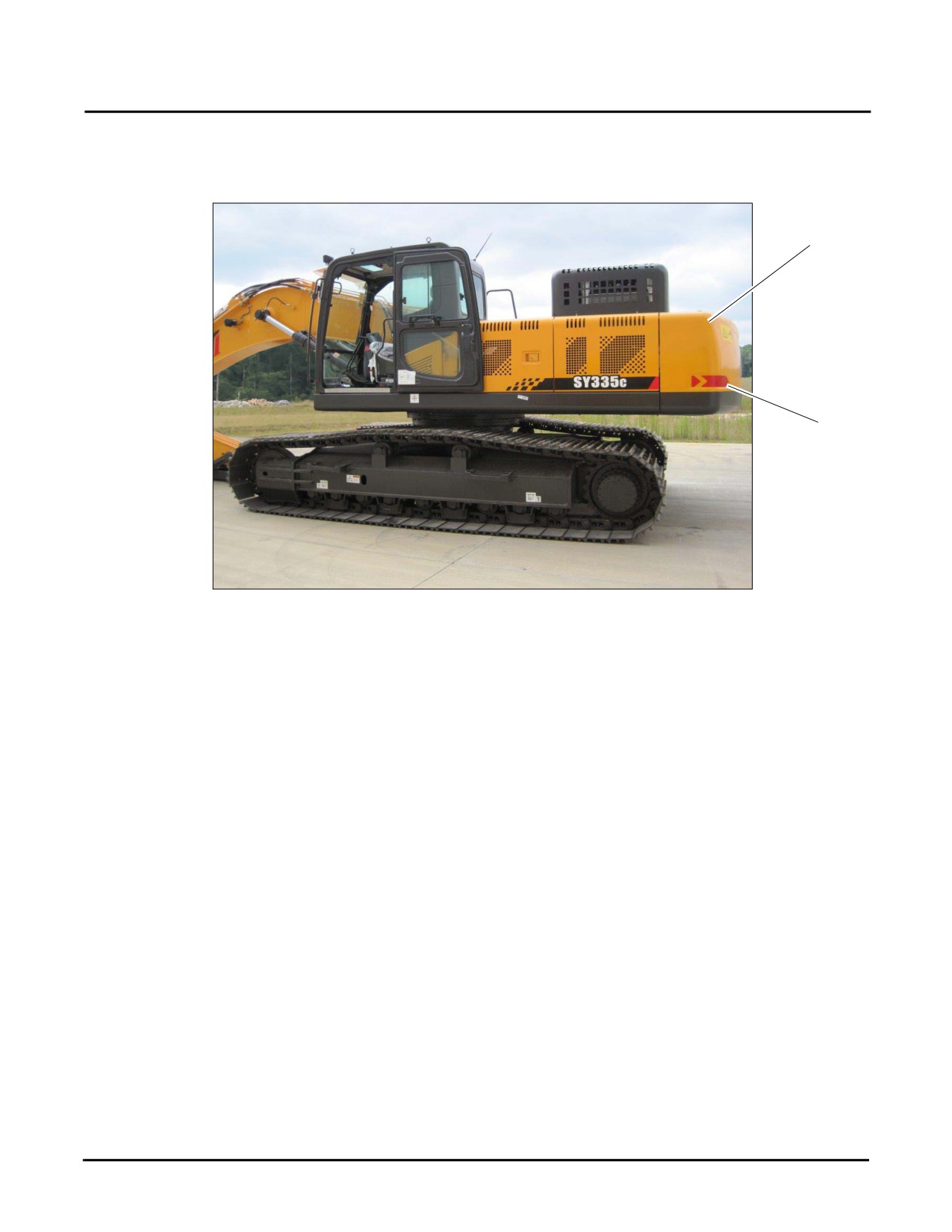
Sheet Metal
Check (a) for loss, damage, loose connections or missing bolts.
a
b
Fig. 5-39
Decals
All safety decals (b) should be visible and complete.
5-34
SY335 Excavator
Daily Maintenance
Drain
Draining the Primary Fuel Filter
DANGER
Never service the fuel system near an open flame or while smoking. Doing so could result in
fire, explosion, serious injury or death.
NOTE: See “Draining Primary Fuel Filter” on page 4-14 for information on how to drain the Primary Fuel
Filter. If an excessive amount of water or contaminant was found while draining the primary fuel
filter, Sany recommends that the fuel tank should be drained.
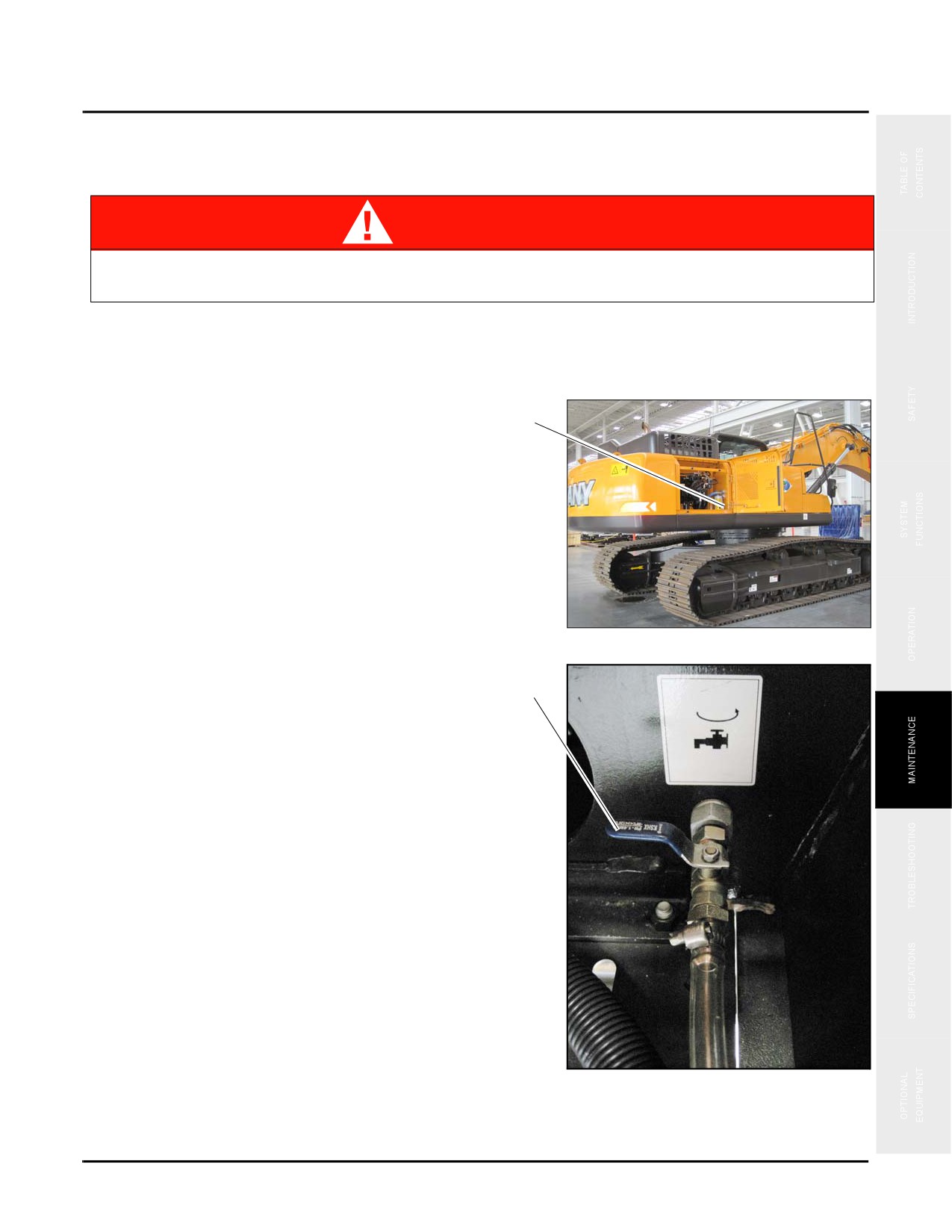
1. Place a large enough container(137 gal/ 520 L) to hold
the drained fuel under the drain valve (c) located below
c
the hydraulic pilot line filter against the wall.
NOTE: See “Fluids & Lubricants” on page 5-11 for
additional information.
Fig. 5-40
2.
Rotate and move the drain valve (d) counterclockwise
to open it.
d
3. Rotate the drain valve (d) clockwise when the flow
from the tank bottom is free of water or contaminant.
Fig. 5-41
5-35
Daily Maintenance
SY335 Excavator
NOTICE
Dispose of the contaminated fuel properly. Failure to do so will violate environmental laws and
ordinances.
4. Start the engine and allow it to run at idle speed, then check for leaks in the fuel system.
5. Repair any leaks, then close and lock the access panel.
5-36
SY335 Excavator
50 Hours of Maintenance
50 HOURS OF MAINTENANCE
NOTICE
Failure to perform the following procedures when and how directed will result in shortened
service life of the machine or a system failure during operation.
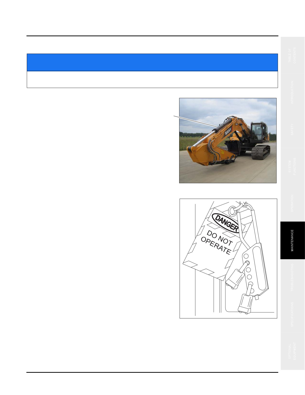
1. Park the machine on a level flat surface (a).
a
Fig. 5-42
2. Follow the Lock-out Tag-out procedure in the Safety
section of this manual. Always allow the systems time to
cool down before proceeding with any service. See
“Lockout/Tagout Procedures” on page 2-21 for details.
NOTE: Obtain the maintenance record for this machine
and complete it at the close of all maintenance
procedures.
3. With the machine secured, proceed with the following:
Change:
•
Engine Oil and Filter - Initial (see page 5-38)
Check:
•
Slewing Gearbox Oil Level (see page 5-24)
•
Air Intake System (see page 5-42)
•
Muffler and Exhaust System (see page 5-43)
Fig. 5-43
•
Hydraulic Hoses (see page 5-44)
•
Batteries (see page 5-45)
•
Crawler Shoe Connecting Pins (see page 5-48)
5-37
50 Hours of Maintenance
SY335 Excavator
•
Crawler Support Roller Mounting Bolts (see page 5-48)
•
Crawler Gearbox Oil Level (see page 5-49)
•
Crawler Drive Sprocket Mounting Bolts (see page 5-50)
•
Track Tension - Initial (see page 5-51)
Lubricate:
•
Slewing Bearing (see page 5-54)
Change
Engine Oil and Filter - Initial
WARNING
Do not perform this task when the engine is hot. Wait for the temperature to cool down before
doing this job. Failure to do so may cause burns or other serious injury.
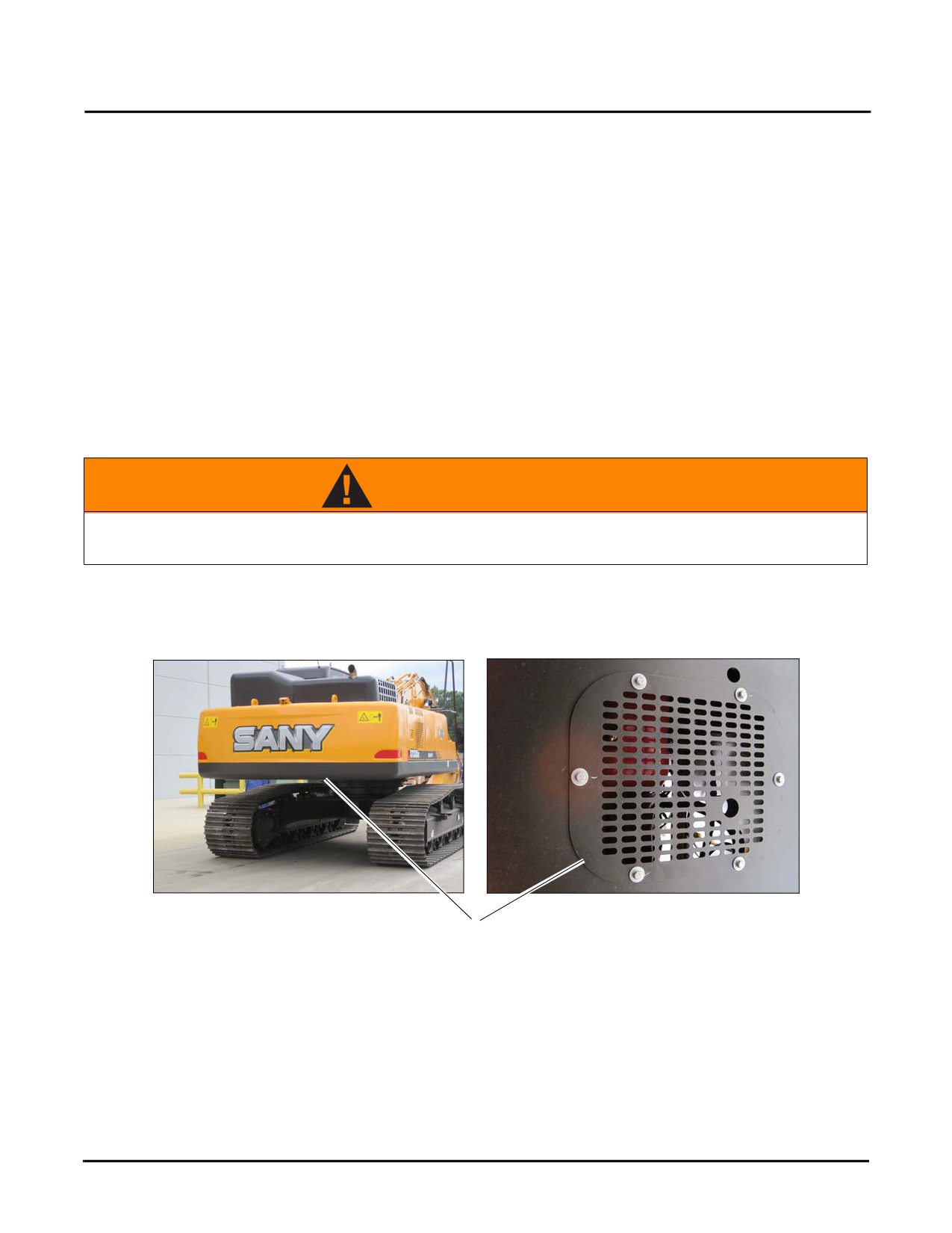
1. Remove the belly plate (a) under the engine compartment.
Fig. 5-44
a
5-38
SY335 Excavator
50 Hours of Maintenance
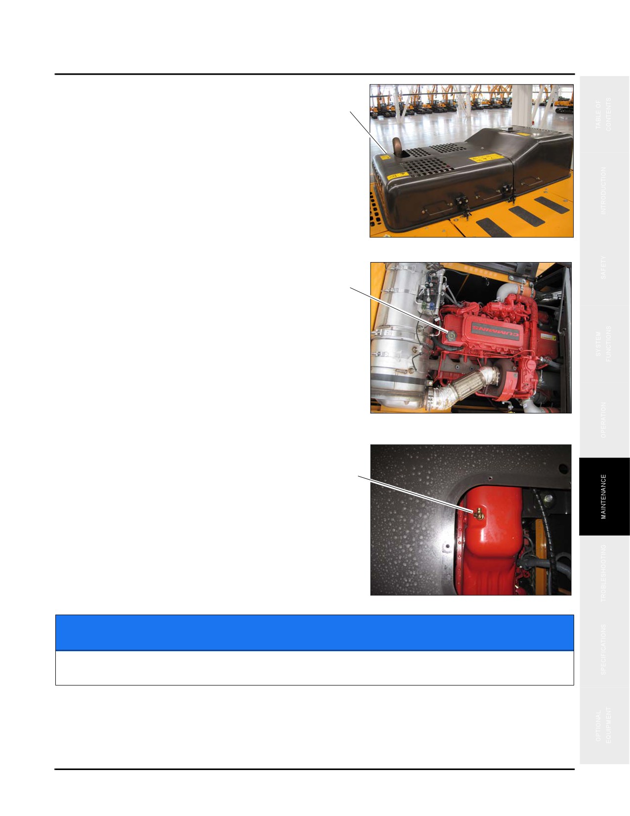
2. Open engine cover (b).
b
Fig. 5-45
3. Remove the engine oil filler cap (c).
c
Fig. 5-46
4. Place a container (at least 6 gal/ 23 L) in size under the
drain valve (d).
d
5. Slowly open the valve to drain all of the oil.
6. Close the valve when all of the oil has drained from the
engine.
7. Replace the belly plate (a).
Fig. 5-47
NOTICE
Dispose of the contaminated oil properly. Failure to do so will violate environmental laws and
ordinances.
5-39
50 Hours of Maintenance
SY335 Excavator
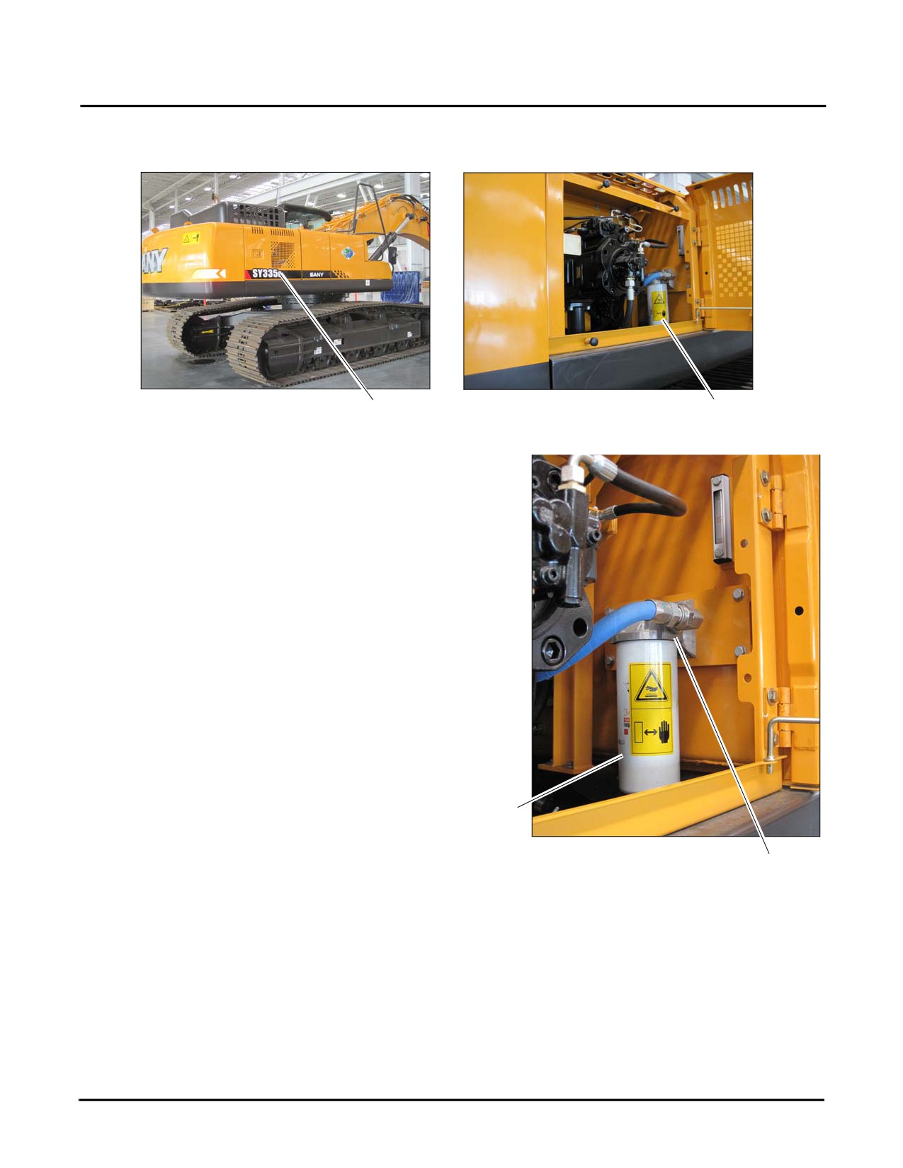
8. Open the right rear access panel (c) and locate the engine oil filter (d).
Fig. 5-48
c
d
9. Turn the engine oil filter (e) to the left to remove the oil
filter.
10. Clean the engine oil filter mount (g).
NOTE: Check the mount for any of the previous seal.
If found remove this used seal to prevent oil
leakage when a new filter is mounted in place.
11. Clean the oil filter mounting surface, then coat the new
filter seal ring with a thin layer of engine oil.
12. Thread the filter into place on its mount until the filter
gasket contacts the filter mount, then tighten the filter
3/4 turn more.
e
Fig. 5-49
g
5-40
SY335 Excavator
50 Hours of Maintenance
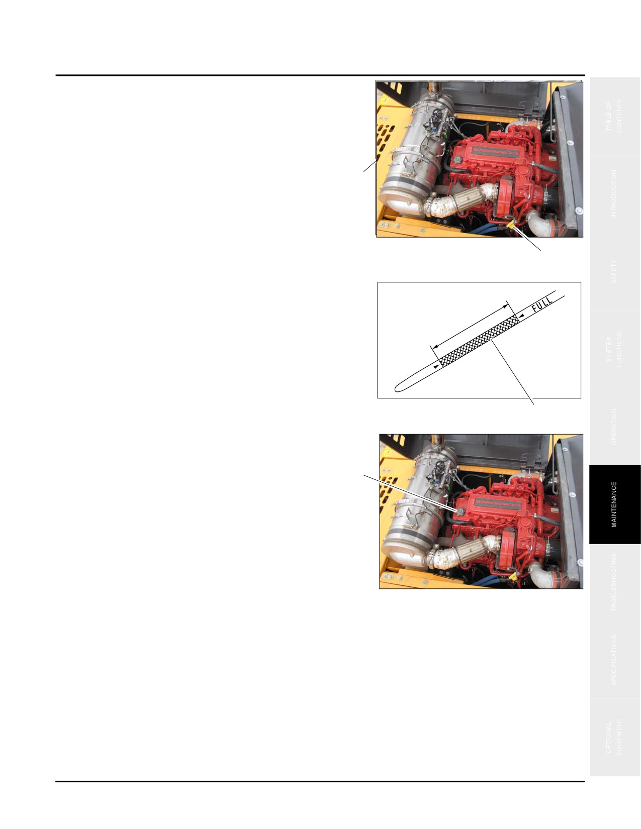
13. Check engine oil dipstick level (k).
h
Fig. 5-51
k
14. Replace oil until the oil level falls between the etched
marks (m).
Fig. 5-52
m
15. Replace engine oil through the fill point
(n). See
“Engine Oil Viscosity/Temperature Data” on page 5-
12.
n
16. After adding the required amount of oil to the engine,
start and run the engine at idle speed for a short time
Fig. 5-53
and check for leaks.
17. Shut the engine down, wait for several minutes, then
remove the dipstick from the engine and note the oil level on the dipstick.
NOTE: The oil level should be within the etched area (m) on the dip stick surface.
18. If necessary, remove the oil filler cap (n), add oil as needed, then reinstall the cap.
5-41
50 Hours of Maintenance
SY335 Excavator
Check
Air Intake System
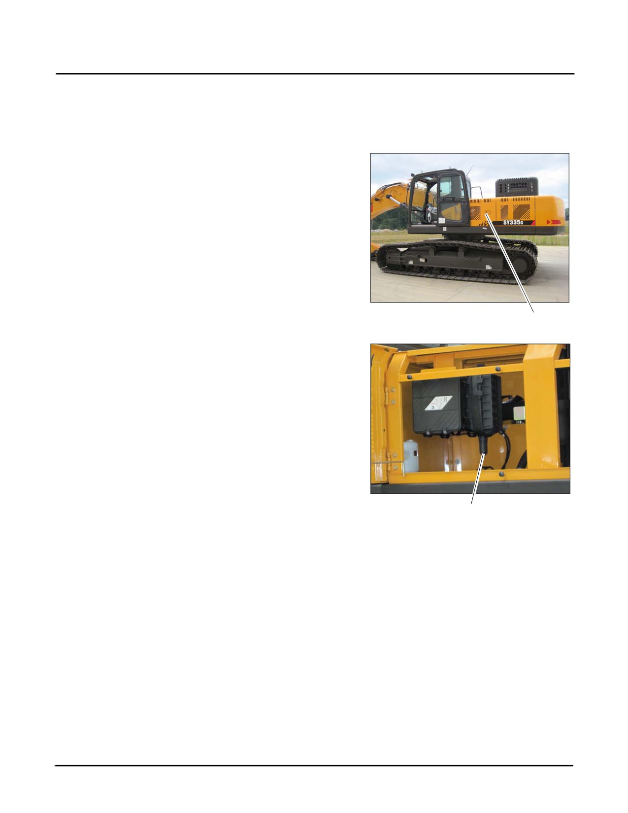
1. Locate the air intake system inside the left side access panel (a).
Fig. 5-54
a
2. Squeeze the dust vacuator (b) mounted at the bottom of
the filter housing to release any dust or debris.
Fig. 5-55
b
5-42
SY335 Excavator
50 Hours of Maintenance
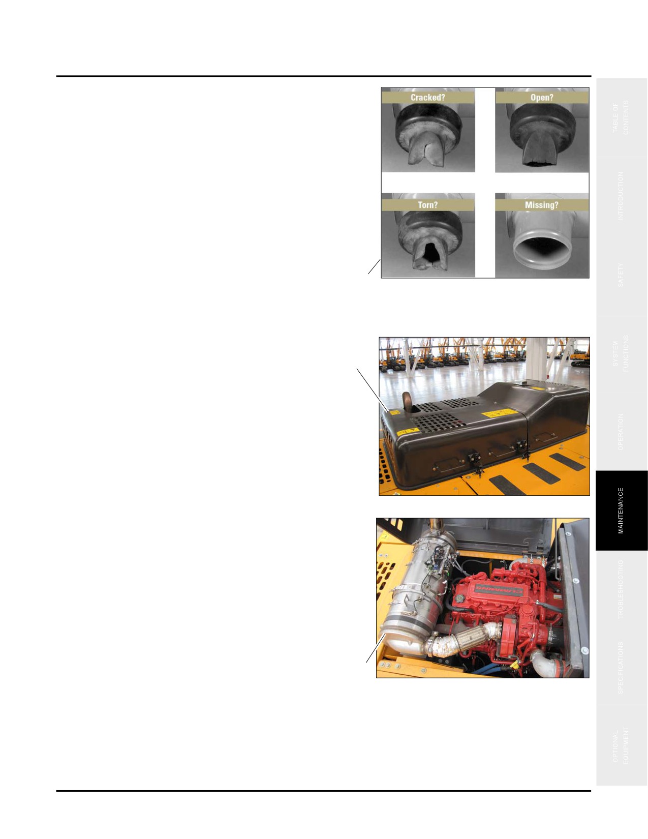
3. Check the condition of the dust vacuator (c) and replace
if required.
NOTE: If the dust vacuator is cracked, torn, remains
open or is missing, dust particles that are
normally expelled can deposit themselves
onto the filter and will shorten air filter
service life.
c
Fig. 5-56
Typical
Muffler and Exhaust System
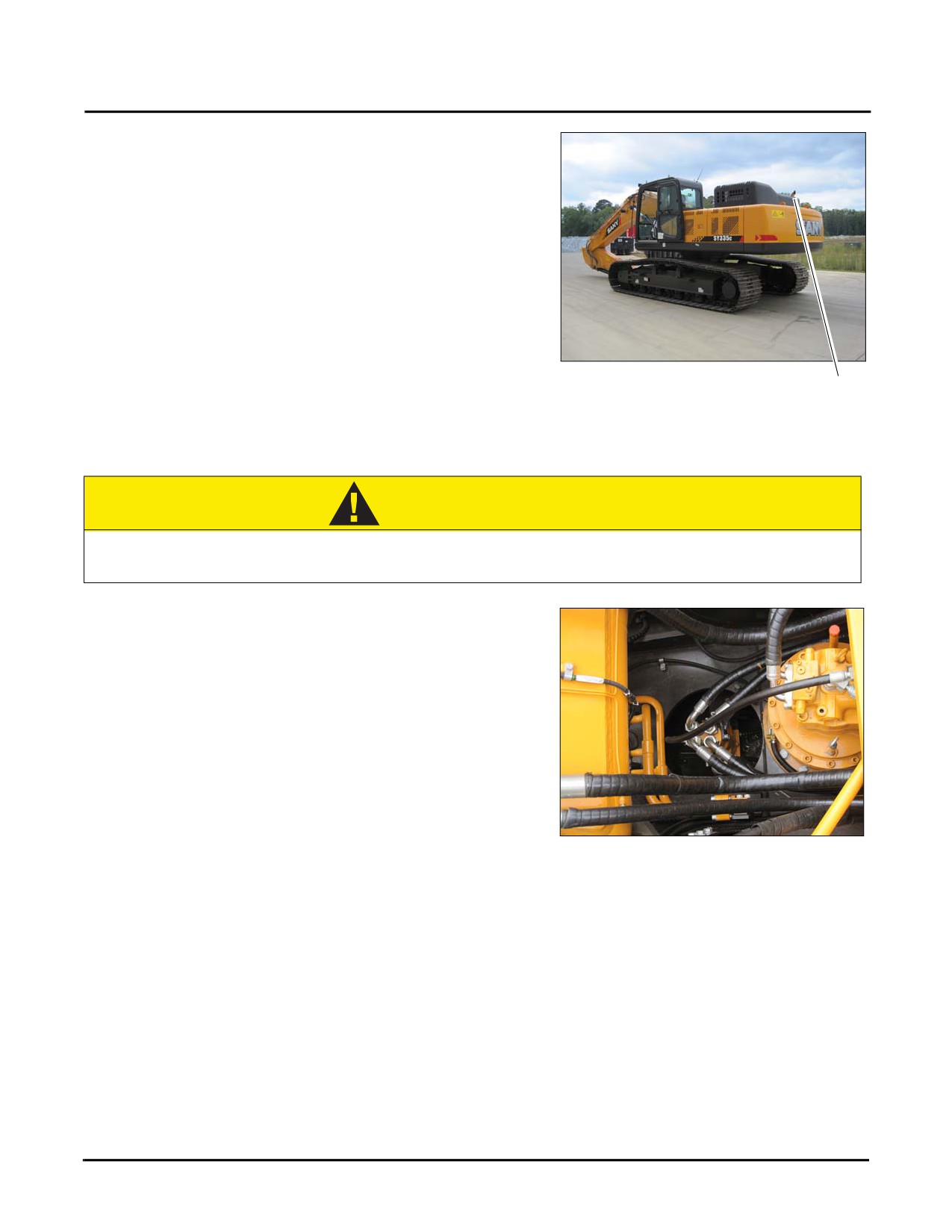
1. Open the engine compartment (a).
a
Fig. 5-57
2. Locate the muffler and exhaust pipe (b) next to the
engine.
b
Fig. 5-58
5-43
50 Hours of Maintenance
SY335 Excavator
3. Inspect the muffler (c) and its mount for leaks or signs
of damage. Be sure the exhaust pipe is clear and not
restricted. Check the connection to the expansion pipe
to be sure there are no signs of leakage.
NOTE: If any abnormality is found, contact your Sany
distributor for repairs.
Fig. 5-59
c
CAUTION
Never operate a machine with a defective exhaust system. Exhaust leaks or a restricted or
damaged exhaust system could cause an unexpected fire leading to minor or major injury.
Hydraulic Hoses
Check all hoses regularly for possible leakage and replace
damaged or leaking hoses immediately, even if there is a
slightest damage.
Any hydraulic pump lines and connectors connected to the
engine chamber must be replaced if they are damaged due to
mechanical /thermal or other effects.
Ensure that there is a sufficient distance from all lines and
hoses to the high temperature engine components
(for
Fig. 5-60
instance, the exhaust system) and that there is no friction
between them.
Possible hose defects are as follows:
•
The couplings slip in the hose
•
Damage, cuts or abrasions in the external rubber layer
•
Hardening, chapping or burning of hose
•
Any cracks, damage or serious corrosion on the couplings
•
Any leakage at the hose couplings
5-44
SY335 Excavator
50 Hours of Maintenance
•
Any twisted, broken, flat or distorted hose
•
Blisters or softness in the external hose layer
Besides the defects listed above, also look for these signs of problems when doing the visual inspection:
•
Oil leakage at the oil orifice of the engine block.
•
Clogging by debris
NOTE: Repair or replace those items as described above.
Batteries
The batteries provide the power supply to start the engine, control electric apparatus, lighting and auxiliary electric
equipment.
CAUTION
Before proceeding with any battery maintenance procedure follow and remember these
points:
• Battery gases are explosive. Never smoke around batteries or expose them to sparks or
open flames.
• Wear personal protective equipment when working with batteries.
• Work in a well-ventilated area.
If battery acid contacts your skin or your eyes, flush the area immediately with fresh water and
seek medical attention.
5-45
50 Hours of Maintenance
SY335 Excavator
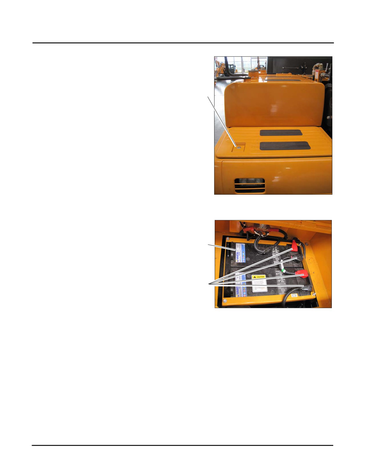
1. Locate, unlock and open the battery compartment access panel (a) on the right front side of the machine.
a
Fig. 5-61
NOTE: Allow several minutes for any accumulated
battery gases to clear before servicing the
batteries (b).
b
2. Check the top surfaces and all the battery connections
(c) for signs of corrosion or dirt build-up. Use a clean
rag to wipe any dirt from the batteries. If corrosion is
found, flush the area with a mix of baking soda and
warm water.
c
3. Remove any trash, tools parts or debris from the battery
compartment.
Fig. 5-62
4. Once the battery service procedures are complete close
the battery compartment access panel.
5-46
SY335 Excavator
50 Hours of Maintenance
Replacement
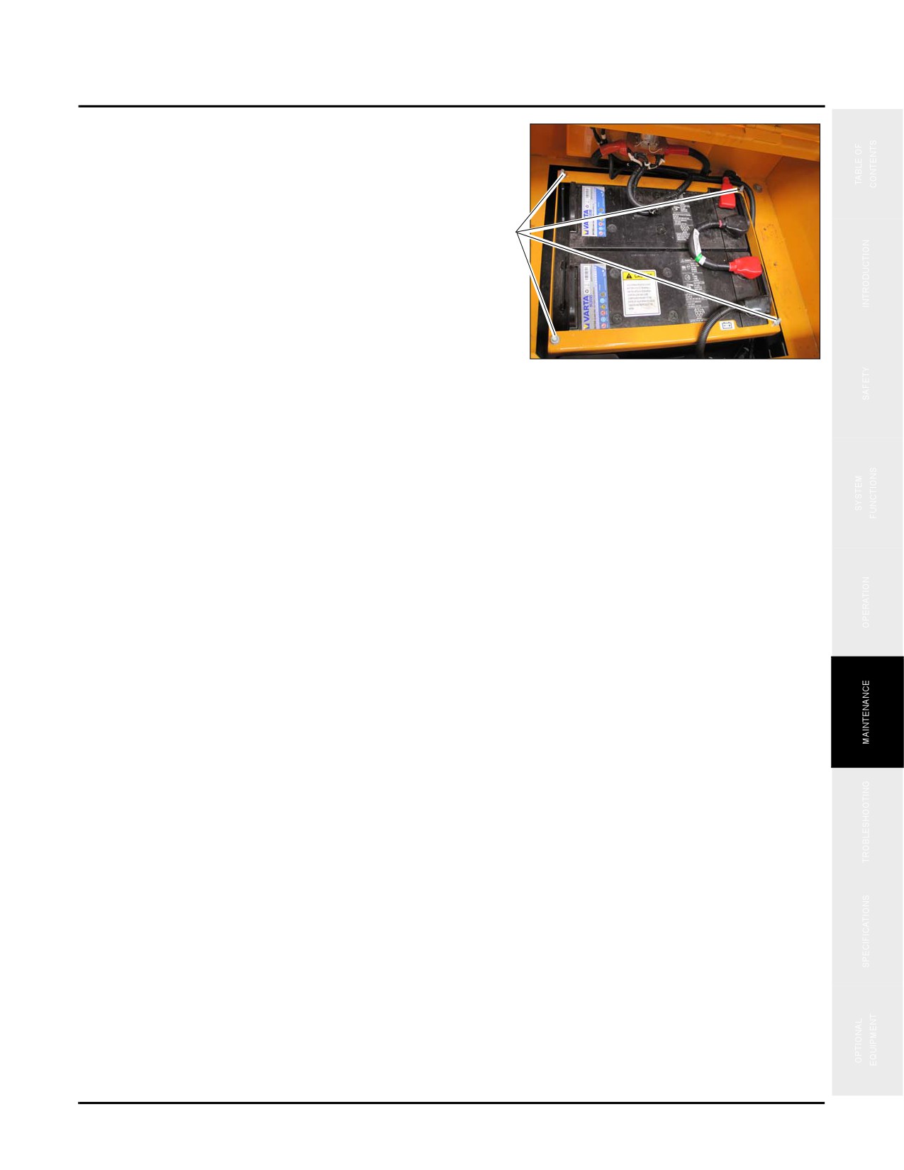
1. Disconnect the black ground (-) battery cables first, then
disconnect the red positive (+) cables last and lift out the
failed battery.
a
2. Remove the battery retaining frame by disconnecting
the four nuts (a) at the corners of the frame and then lift
the frame out taking care not to come in contact with the
battery terminals.
3. Install the new battery (or batteries) inside the battery
compartment positioned correctly.
Fig. 5-63
4. Install the battery retaining frame following the
directions shown in step 1 in reverse.
5. Connect the red positive (+) cables first then the black ground (-) cables afterwards.
NOTE: Both 12-volt batteries are attached in series. Be sure they are installed in the same manner.
6. Torque the battery cable clamps to 7.2 lbf·ft (9.8 N·m).
NOTE: Dispose of the old batteries properly.
5-47
50 Hours of Maintenance
SY335 Excavator
Crawler Shoe Connecting Pins
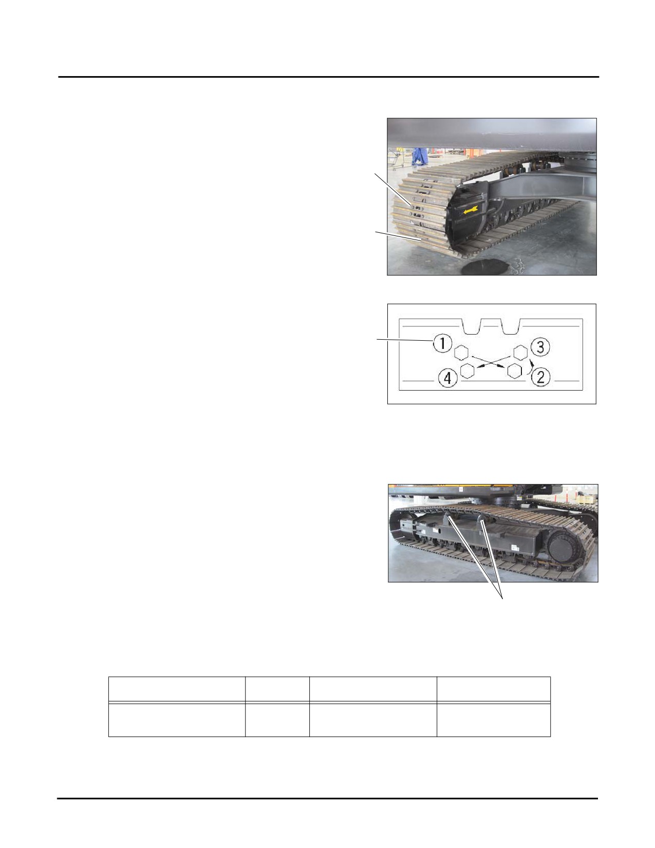
1. Ensure that all retaining bolts (a) are properly in place
at each pair of crawler shoes (b) and not broken, bent or
damaged.
a
b
Fig. 5-64
2. If the bolts are loose, tighten them in sequence (c) to
440-500 lb ft (61-69 kgf) ensuring the nuts and track
shoe are in close contact with the link mating surface.
c
Fig. 5-65
Crawler Support Roller Mounting Bolts
1. Inspect the mounting bolts (a) that secure the support
rollers to the side frame for rust, damage or looseness.
2. Replace any damaged or defective bolts and tighten any
loose bolts.
Fig. 5-66
a
NOTE: Use thread sealant when reinstalling loose bolts and installing new bolts, tightening each of them to
the following values.
Item
Diameter
Torque Value
Thread Sealant
399 - 485 ft•lb
Mounting Bolt GB5782
M18x100
Anaerobic sealant
(540 - 658 N•m)
5-48
SY335 Excavator
50 Hours of Maintenance
Crawler Gearbox Oil Level
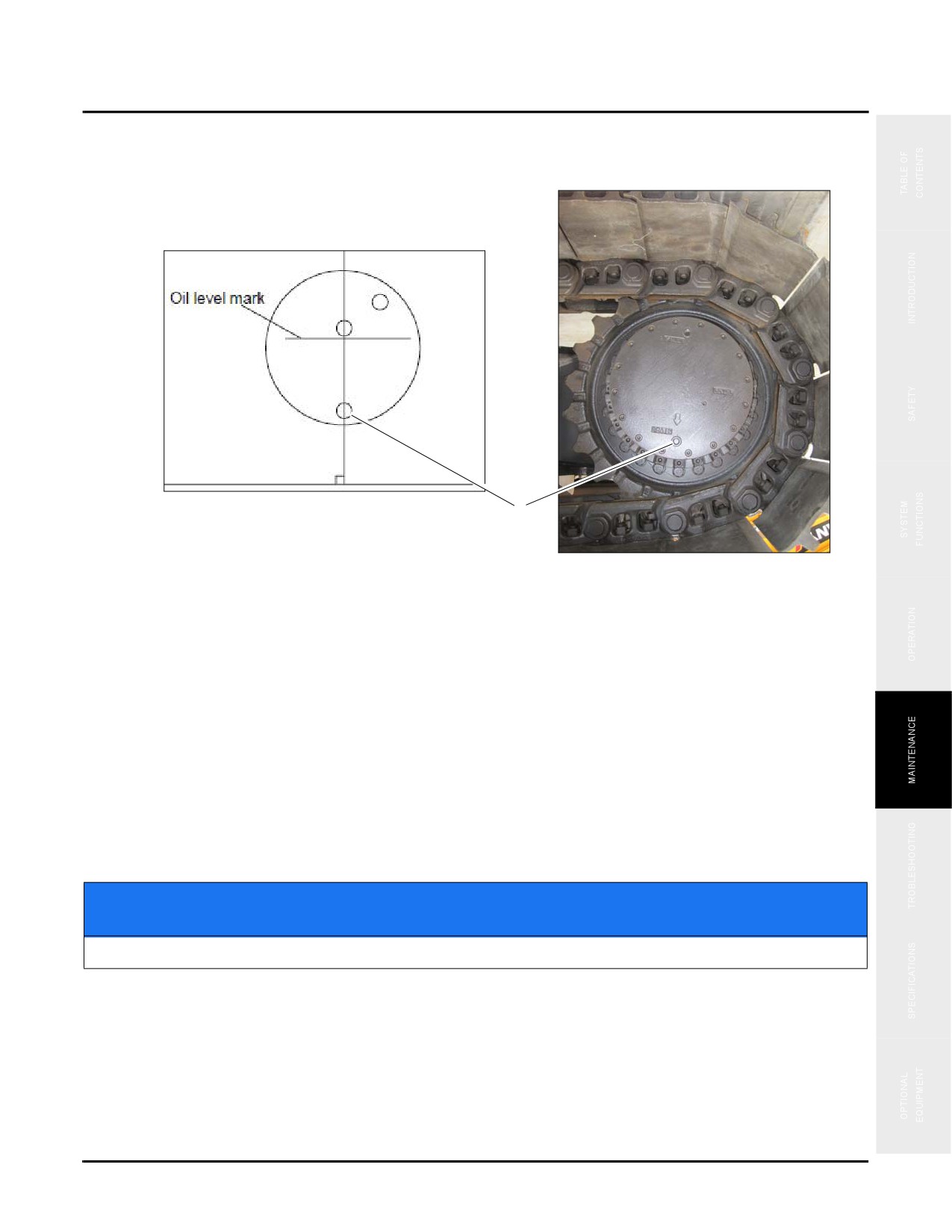
1. Park the crane on firm, level ground with the drain plug (a) positioned at the bottom.
Fig. 5-67
a
2. With the machine running, listen for abnormal noise from inside the crawler gearbox.
NOTE: Contact Sany if abnormal noise is heard.
3. Stop the machine, then remove the check plug (b) and visually check to be sure the oil level is within 0.4 in. (10
mm) of the bottom of the check plug hole.
4. If the oil level is low, add oil through the check plug hole (c) until the level is within 0.4 in. (10 mm) of the
bottom of the hole.
NOTE: See “Fluids & Lubricants” on page 5-11 for more information if needed.
NOTICE
Do not overfill the case or damage to the case seals may result.
5. Install and tighten the check plug to 50 ft•lb (68 N•m).
6. Check for external leakage.
5-49
50 Hours of Maintenance
SY335 Excavator
NOTICE
If oil leakage is found during the oil level inspection, stop the inspection, locate and repair
the cause of the oil leakage. Failure to do this may result in low oil level during operation and
component failure.
Crawler Drive Sprocket Mounting Bolts
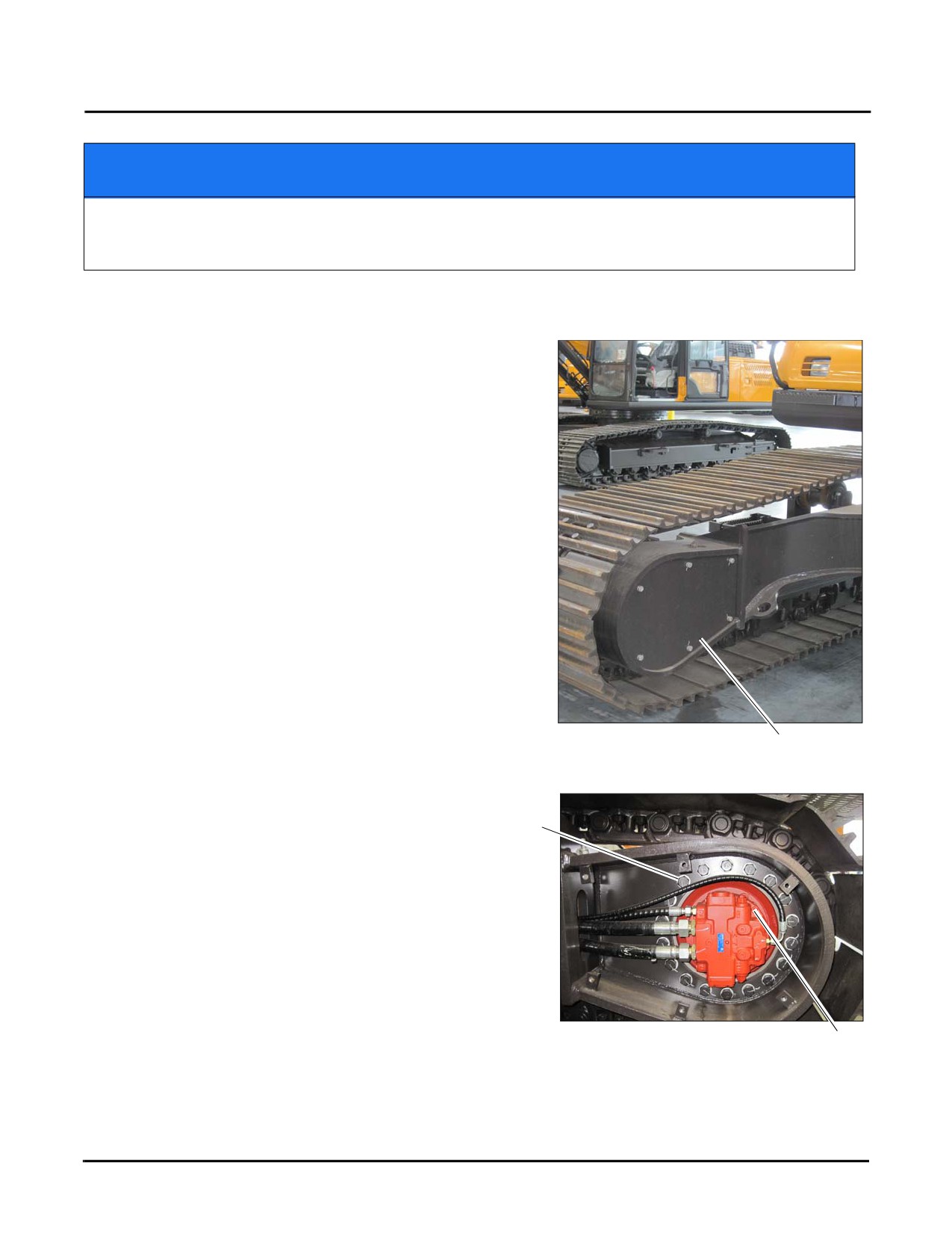
1. Locate and remove the Crawler Drive Sprocket cover (a)
Fig. 5-68
a
2. Inspect all of the crawler drive sprocket mounting bolts
(b) and the hydraulic motor mounting bolts (c) for rust,
b
damage or looseness.
3. Replace any damaged or defective bolts and retighten
any loose bolts.
NOTE: Use anaerobic thread sealant when reinstalling
loose bolts and installing new bolts, tightening
all of them to the following values:
Fig. 5-69
c
5-50
SY335 Excavator
50 Hours of Maintenance
NOTE: Contact Sany if any abnormalities are found.
Item
Diameter
Grade
Torque Value
Thread Sealant
Drive Sprocket Mounting Bolt
M24
738 ft•lb (1,000 N•m)
10.9
Anaerobic sealant
Hydraulic Motor Mounting Bolt
M20
516 ft•lb (700 N•m)
Track Tension - Initial
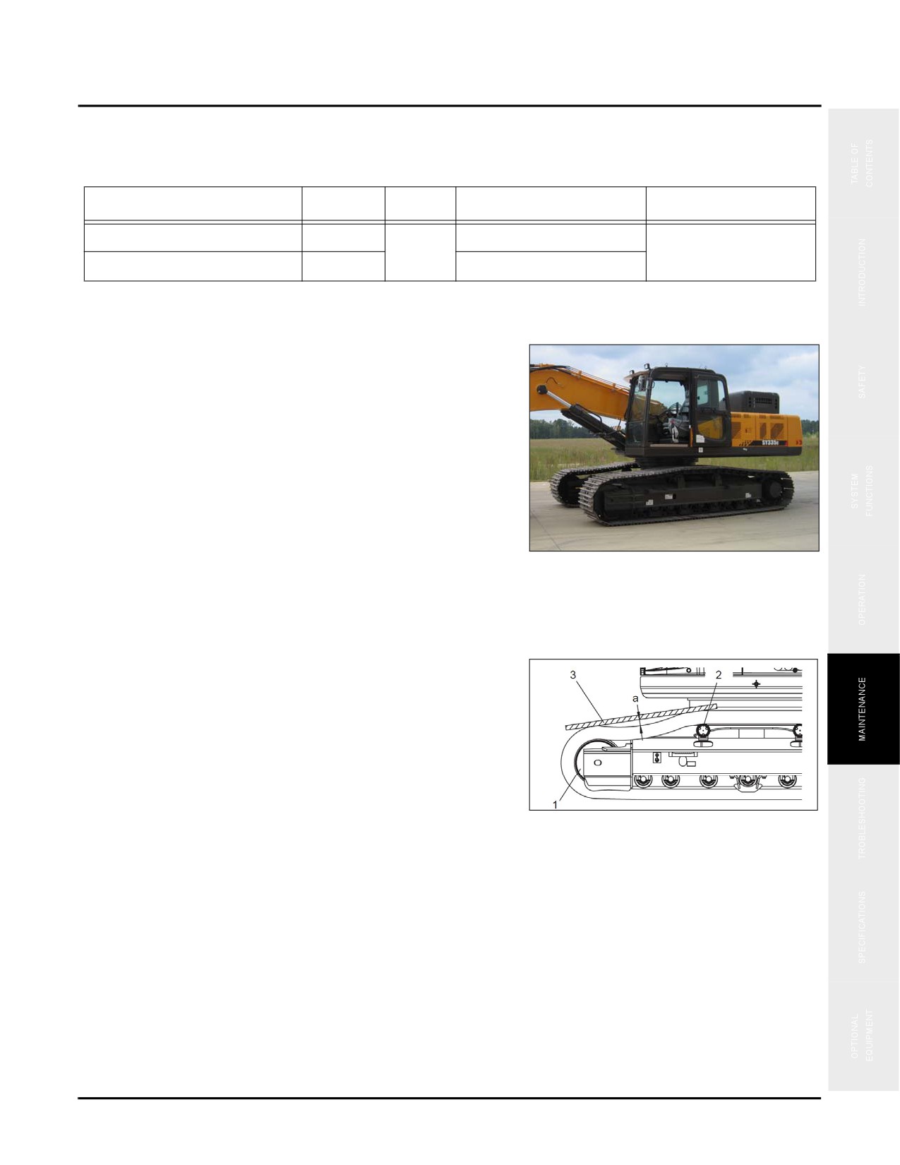
If track tension is noticeably loose, operate the machine
with the engine at an idle speed. Travel forward a distance
of about 4 meters (13 feet) on level flat clear surface, then
stop the machine.
Fig. 5-70
Measure track tension:
1. Place a straight edge (3) between track idler wheel (1)
and rollers (2), then measure the track droop value “a”
as shown in the illustration. The required measurement
should be 0.4-1.2 in (10-30 mm)
NOTE: Be sure the surface is flat and stable.
2. If the tension is outside standard range parameters,
adjust as required.
Fig. 5-71
Typical
5-51
50 Hours of Maintenance
SY335 Excavator
Increase track tension:
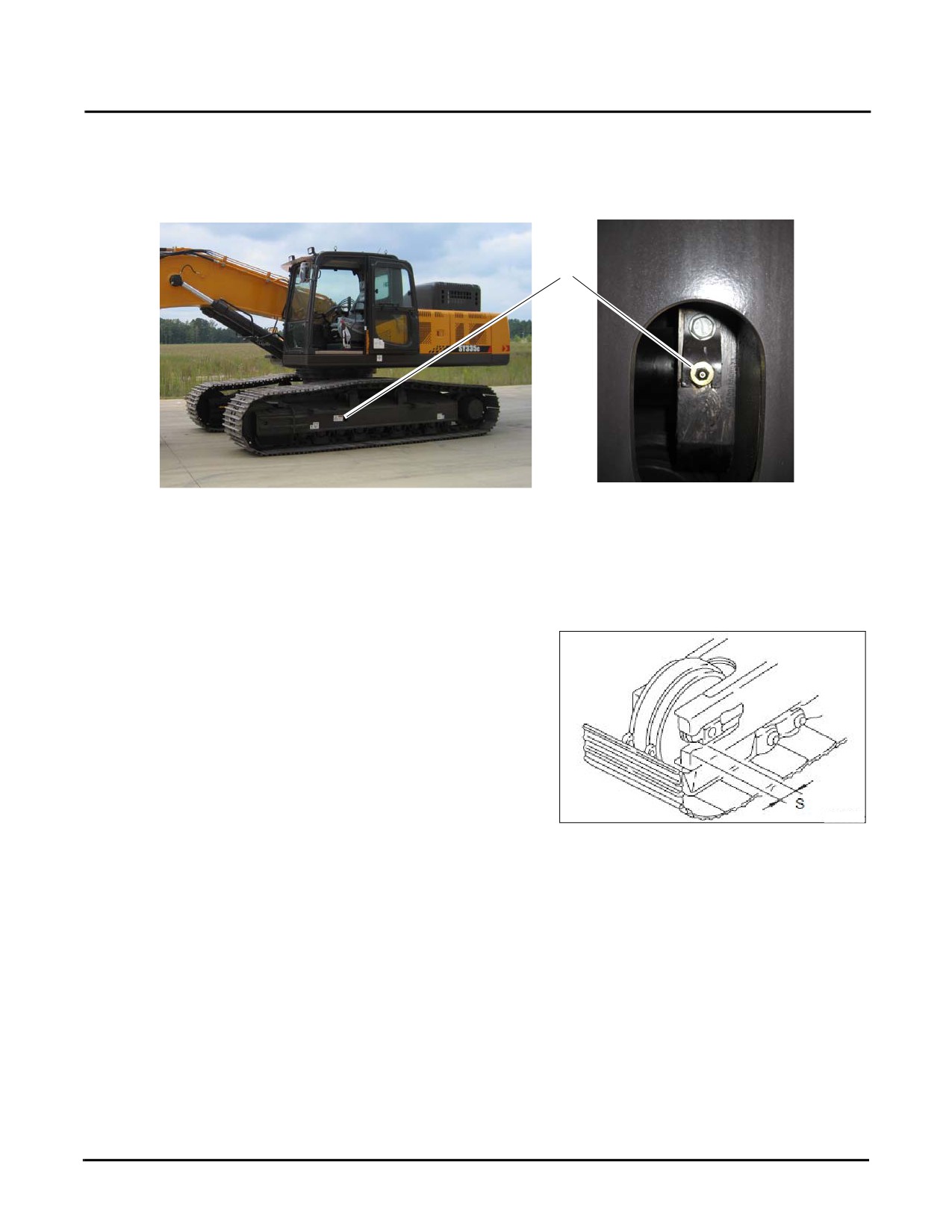
1. Add grease through the grease fitting (a). (The grease fitting (a) and the screw plug are integral.)
a
Fig. 5-72
2. Slowly travel the machine forward 23-26 ft (7-8 m), stop and recheck to see if the track tension is suitable.
3. Add additional grease through the grease fitting if it is still beyond the required range.
NOTE: If the tension is still loose, when the distance
[S] becomes null (0), it is probably because
the bolt and bushing are worn. The bolt or
bushing must be repaired or replaced. Contact
your Sany dealer for this repair.
Fig. 5-73
5-52
SY335 Excavator
50 Hours of Maintenance
Reduce track tension:
DANGER
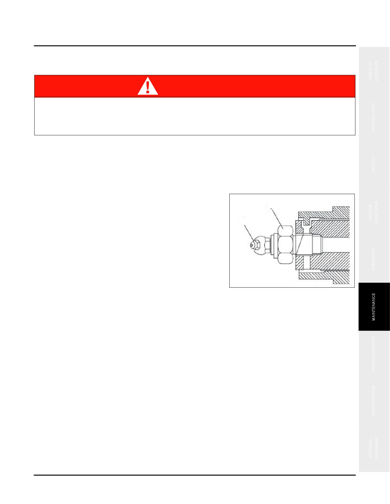
Do not loosen grease fitting (b)! This grease fitting is under pressure and can come out of the
track tensioning cylinder quickly and forcefully.
Failure to follow these instruction will cause serious injury or death!
1. Ensure that there is no gravel or mud between the sprocket and the track link before decreasing track tension.
2. Position yourself off to the side, not the front of the grease valve (a). Using the proper tools slowly loosen
grease valve (a) counterclockwise, in 90° increments (one quarter turn) to decrease track tension.
NOTE: The grease will come out behind the grease
valve.
a
3. If the grease does not come out smoothly, move the
machine back and forth for a short distance.
b
4. Check track tension, when it is correct turn grease valve
(a) clockwise and torque to 35 lb/ft (47N·m).
5. Move the machine forward at low idle speed, to a
distance that is equivalent to the length of an unfolded
track, and then park the machine.
Fig. 5-74
6. Check track tension again. Readjust if it is still beyond
the standard range.
7. Tighten grease valve (a), torque to 108 ft/lb (15 kgf/m).
5-53
50 Hours of Maintenance
SY335 Excavator
Lubricate
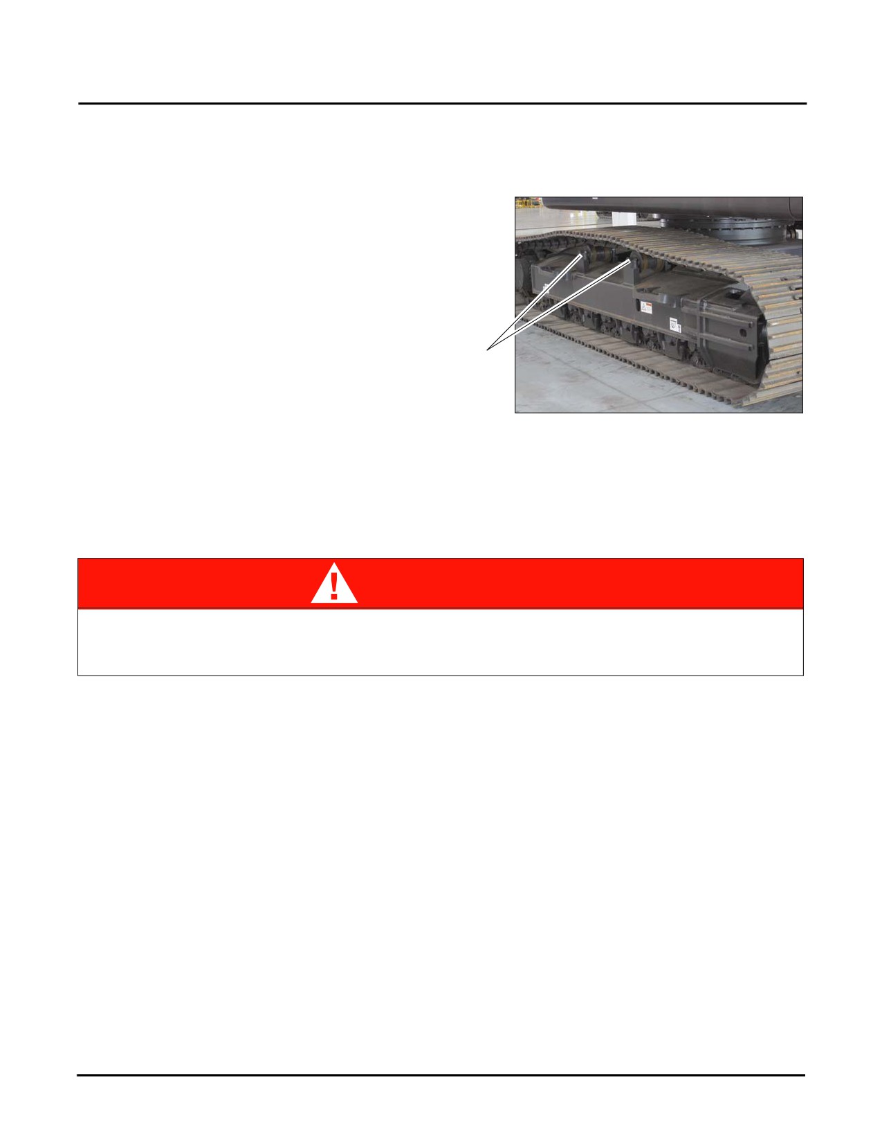
NOTE: Add grease to any component that produced abnormal noise regardless of the greasing schedule.
NOTE: After operating in water, the machine’s wet
support rollers (a) should be greased.
a
Slewing Turntable Bearing
Fig. 5-75
NOTE: It will be necessary to power up the machinery
and have one person perform the lubrication
procedure inspection while the crane operator slowly slews the crane 45 degrees at a time through a
complete circle, 360 degrees.
DANGER
Do not perform this check unless you have another person helping/viewing you who can
clearly communicate with the operator. Slew the crane slowly and insure that the person
lubricating the turntable does not place any body part where it may be crushed.
5-54
SY335 Excavator
50 Hours of Maintenance
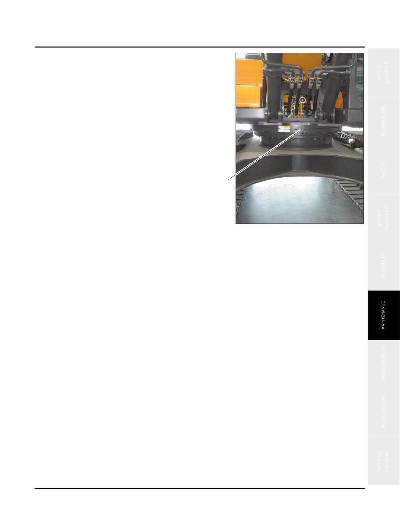
1. Inject clean, lubricating grease at the fittings (a) on the
slewing bearing until the grease seeps out of the seal.
NOTE: See “Fluids & Lubricants” on page 5-11 for the
correct type of grease.
2. Check the seal condition and if it leaks replace it
immediately.
a
Fig. 5-76
5-55
50 Hours of Maintenance
SY335 Excavator
Work Equipment
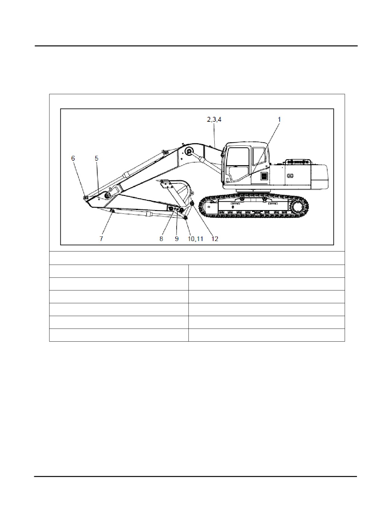
Inject grease through the work equipment greasing points as indicated in the following illustration. and as shown in
the decal next to the cab door.See “Fluids & Lubricants” on page 5-11 for additional information.
The following is a summary of lubrication points on the machine..
Fig. 5-77
1. Boom Cylinder Root Pin (2)
7. Bucket Cylinder Root Pin (1)
2. Boom Cylinder Root Pin(2)
8. Bucket-Rod Joining Pin (1)
3. Boom Cylinder Piston Rod End (2)
9. Arm-Bucket Joining Pin (1)
4. Arm Cylinder Root Pin (1)
10: Rod Joining Pin (2)
5. Boom-Arm Joining Pin (2)
11. Bucket Cylinder Piston Rod End (1)
6. Arm Cylinder Piston Rod End (1)
12. Bucket-Rod Joining Pin (1)
NOTE: The following pages give additional details on each of the lubrication points shown above.
5-56
SY335 Excavator
50 Hours of Maintenance
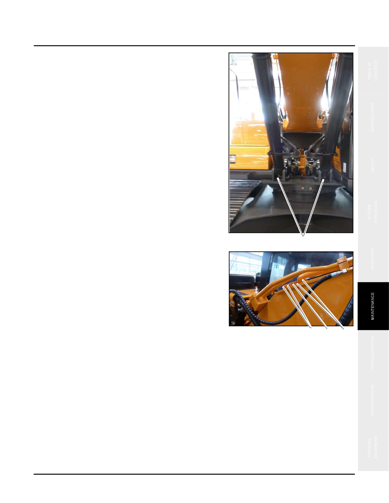
1. Inject grease the two boom cylinder root pin fittings (a).
Fig. 5-78
a
2. Inject grease into the two boom pin fittings (b), the two
boom cylinder piston rod end fittings (c), and the arm
cylinder root pin (d) fitting.
NOTE: These fittings are mounted on the top of the
boom near the base with lines leading to the
bearings.
Fig. 5-79
b d c
5-57