SANY Excavator SY335 (Part Number: 11282013). Safety, Operation & Maintenance Manual - page 9

Machine Dimensions & Specifications
SY335 Excavator
Machine Parameters
Weight (loaded - full fuel
tank, operator and stan-
82,371 lb (37,363 kg)
dard bucket)
Model No.
Cummins, QSL9
6 in-line cylinders, 4-stroke, turbo pressurized,
Type
centralized air-colling, electric controls, etc.
ECU completely electric-controlled system of
Control Method
CAN bus
Engine
Power Rating
275hp/2,200 rpm(205kw/2,200rpm)
Torque Rating
895 lbf-ft/1,500 rpm (1213 Nm/1,500 rpm)
Exhaust Gas Standard
EU Tier 4i
Main Pump Flow
2 x 10⁶ gal (2 x 400 l)
Swing Speed
9.8 rpm
Travel Speed
2.1 / 3.2mph (3.4 /5.1km/h)
Draw Bar Pull (Tractive
70,140 lbf (312 kN)
Effort)
Max Arm Digging Force
37,093 lbf (165 kN)
Max Bucket Digging
49,458 lbf (220 kN)
Force
Number of Upper Rollers
2
Number of Lower Rollers
9
Fuel Tank Capacity
137 gal (520 l)
Hydraulic Tank Capacity
108.3 gal (410 l)
Cooling System Capacity
12.5 gal (48 l)
Engine Oil Capacity
7.67 gal (29 l)
Ground Pressure
6.5 psi (44.6 kPa)
(800 mm Shoes)
7-4
Safety, Operation & Maintenance Manual —November 28, 2013
SY335 Excavator
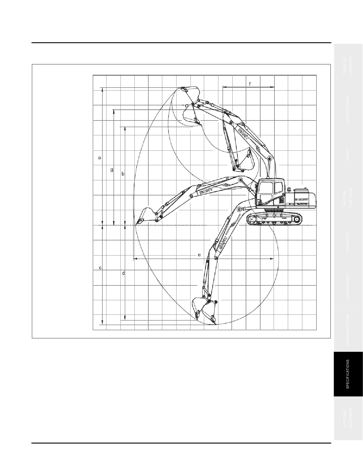
Operating Ranges
OPERATING RANGES
Fig. 7-8
Safety, Operation & Maintenance Manual —November 28, 2013
7-5

Operating Ranges
SY335 Excavator
Operating Range
a
Max Digging Height
33’ 3” (10,135 mm)
b
Max Dumping Height
24’ 3” (7,391 mm)
c
Max Digging Depth
24’ 2” (7,377 mm)
d
Max Vertical Wall Digging Depth
23’ 1” (7,047 mm)
e
Max Digging Reach
36’ 5” (11,103 mm)
f
Min Swing Radius
14’ 7” (4,462 mm)
g
Max Height at Minimum Swing Radius
28’ (8,527 mm)
7-6
Safety, Operation & Maintenance Manual —November 28, 2013
SY335 Excavator
Optional Equipment
Optional Equipment
Optional Equipment Safety Equipment
8-2
Optional Equipment Selection
8-2
Read Equipment Instructions
8-2
Removal And Installation Precautions
8-2
Optional Equipment Operation Precautions
8-2
Optional Equipment System Functions
8-4
Component Location and Function
8-4
Stop Valve
8-4
Selector Valve
8-5
Hydraulic Circuit
8-6
Optional Tool Selection
8-7
Optional Equipment Operation
8-10
Attach Optional Equipment
8-10
Optional Equipment Control
8-13
Hydraulic Breaker Controls
8-14
Hydraulic Shears Controls
8-14
Disconnecting Optional Equipment
8-15
WARNING
Read and understand all safety precautions and
instructions in this manual before reading any
other manuals provided with this equipment and
before operating or servicing it. Failure to do this
can cause property damage, personal injury or
death.
Safety, Operation & Maintenance Manual — November 28, 2013
8-1
Optional Equipment Safety Equipment
SY335 Excavator
OPTIONAL EQUIPMENT SAFETY EQUIPMENT
Be careful when installing any optional equipment to your machine. The following precautions must be strictly
observed when selecting, installing and operating optional equipment.
Optional Equipment Selection
Please consult a authorized dealer before installing any optional equipment on your machine.
Depending on the type of optional equipment selected, protective structures (such as front guards or top guards)
may need to be installed on the machine.
Install only Sany-approved optional equipment. assumes no responsibility to accidents, loss or
failures caused by any optional equipment that has not been approved by Sany.
Read Equipment Instructions
Carefully read and understand the optional equipment instruction manual before installing and operating any
optional equipment. If your operation and maintenance manual is missing or broken, please contact the
manufacturer of the optional equipment or Sany's authorized dealer to obtain a new one.
Removal And Installation Precautions
Observe the following in order to ensure safety when removing or installing optional equipment:
•
Remove or install equipment only on a hard, level surface.
•
Use a crane when handling heavy objects weighting more than 55 lbs (25 kg).
•
Never stand under the boom of a crane holding any objects.
•
Do not operate your machine when an object is being lifted on to it with a crane.
•
Ensure your machine is well balanced and supported whenever you add or remove a heavy piece of
equipment.
•
For more information about removal and installation please consult any authorized dealer.
Optional Equipment Operation Precautions
Keep the following procedures in mind when installing any optional equipment. Prior to the operation, move your
machine to a safe area and test it’s operation. Make sure that you know how it will move with an optional piece of
equipment, the machine’s center of gravity, and working range.
•
Ensure the machine is well balanced and does not list to one side or another.
•
Maintain a safe distance to all surrounding barriers during machine operations.
8-2
Safety, Operation & Maintenance Manual — November 28, 2013
SY335 Excavator
Optional Equipment Safety Equipment
•
Note the following points when installing optional equipment:
•
Heavy optional equipment requires a larger space to swing. There might be the danger of impacting
other objects if the machine swinging range has not been calculated accurately. A larger space must be
prepared before performing swinging the machine.
•
Never swing, lower or stop your machine suddenly in order to prevent it from tipping over.
•
Never extend or retract the boom cylinder suddenly in order to prevent impact that may cause the
machine to tip.
Safety, Operation & Maintenance Manual — November 28, 2013
8-3
Optional Equipment System Functions
SY335 Excavator
OPTIONAL EQUIPMENT SYSTEM FUNCTIONS
Component Location and Function
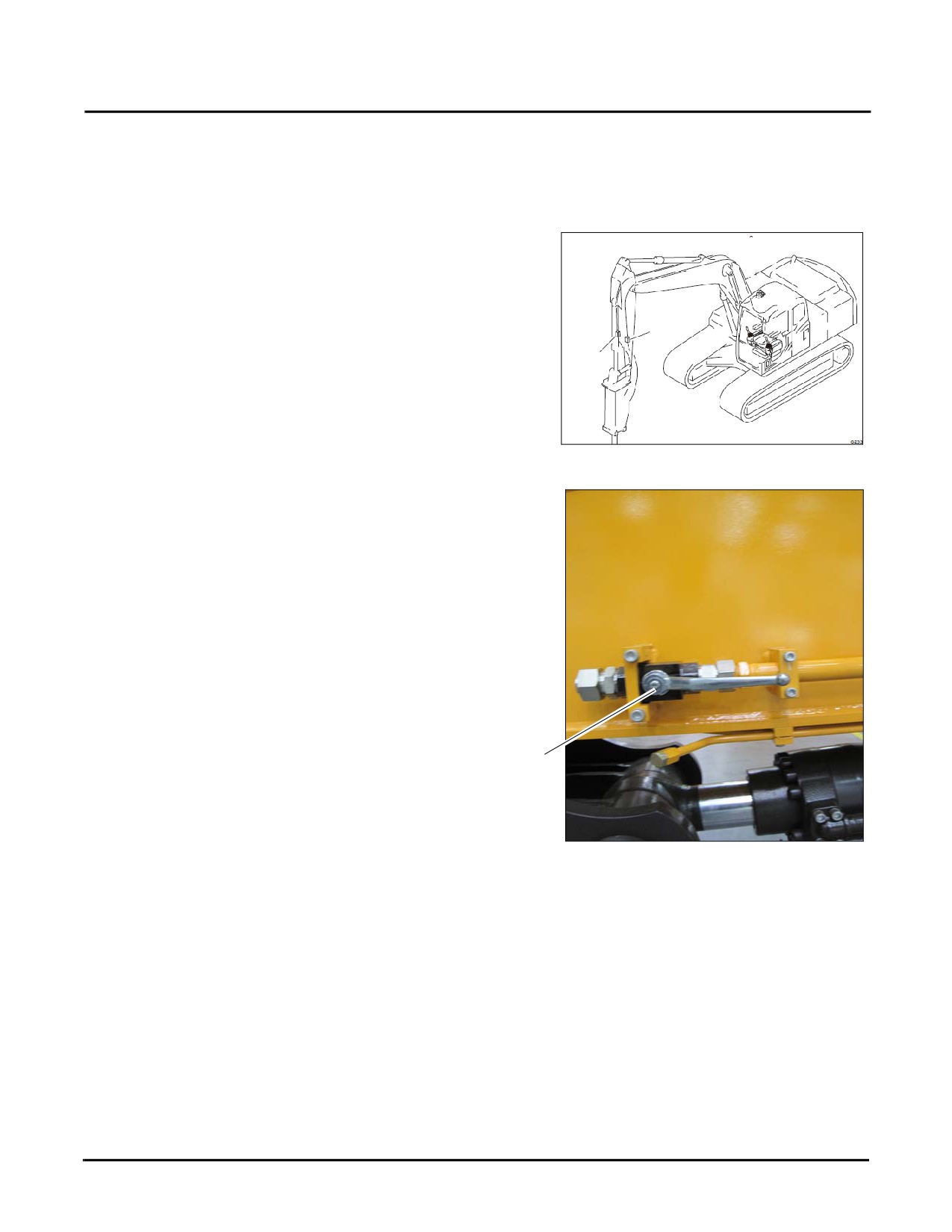
There are two stop valves located on the boom arm and a
selector valve located near the boom base in the center of
the machine.
Stop Valve
1
1
The stop valve (1) stops or allows flow of the hydraulic
1
fluid.
Fig. 8-1
•
FREE position (a) allows flow of the hydraulic
fluid.
NOTE: FREE position allows flow of hydraulic fluid.
(The handle is parallel to the machine arm).
a
Fig. 8-2
8-4
Safety, Operation & Maintenance Manual — November 28, 2013
SY335 Excavator
Optional Equipment System Functions
•
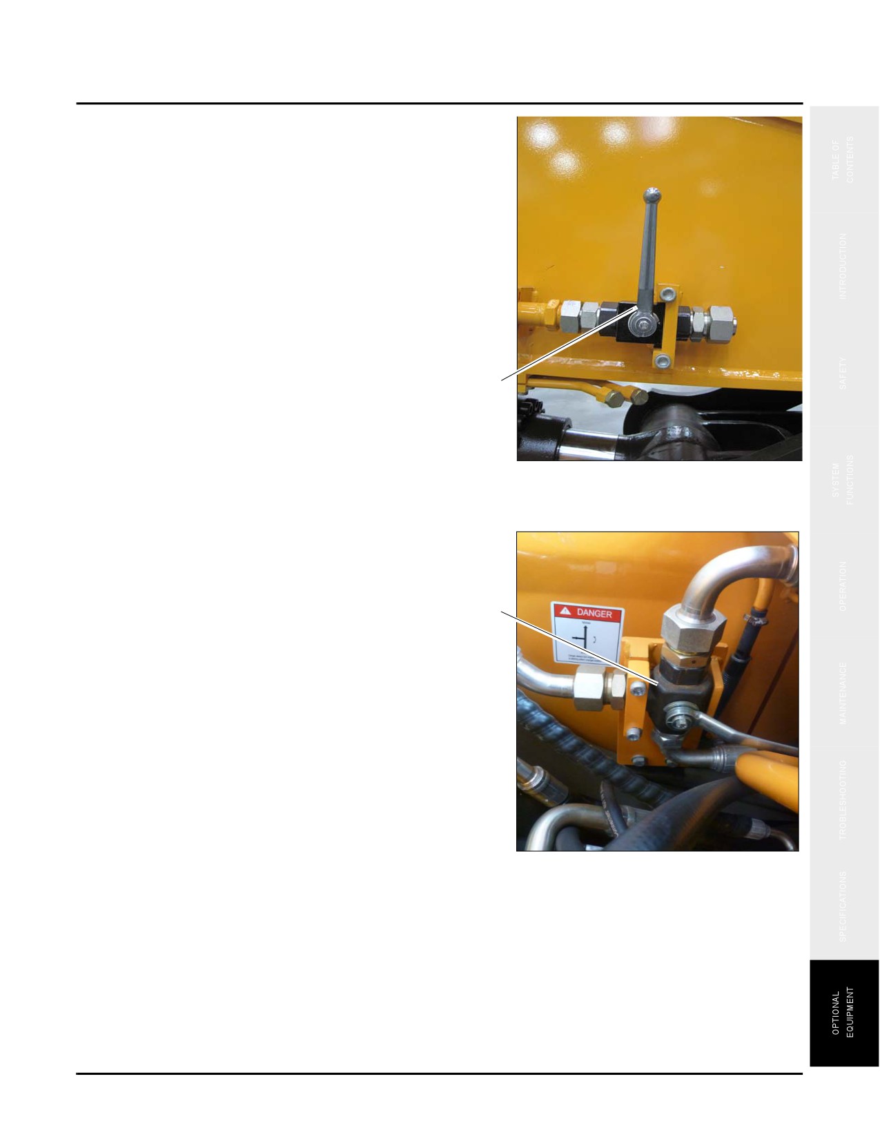
LOCK position (b) stops flow of the hydraulic
fluid. Switch the valve to LOCK position when
removing or installing an optional equipment.
NOTE: LOCK position stops flow of hydraulic fluid.
(The arrow is perpendicular to arm length).
b
Fig. 8-3
Selector Valve
The selector valve
(c) changes the flow direction of
hydraulic fluid. The change of direction is made according
to the operating mode selected. The operating mode must be
applicable to the installed equipment.
c
NOTE: See “Optional Tool Selection” on page 8-7.
Fig. 8-4
Typical
Safety, Operation & Maintenance Manual — November 28, 2013
8-5
Optional Equipment System Functions
SY335 Excavator
Hydraulic Circuit
NOTE: Standard set pressure of the safety valve was set at the factory before delivery. Further adjustment may
be needed depending on the type of attachment. In this case, please contact Sany dealer for
adjustment.
Set the operating mode on the monitor as per the following standards according to the type of optional equipment.
The pressures set for the safety valve and for the switch of hydraulic line are determined by the operating mode
selected.
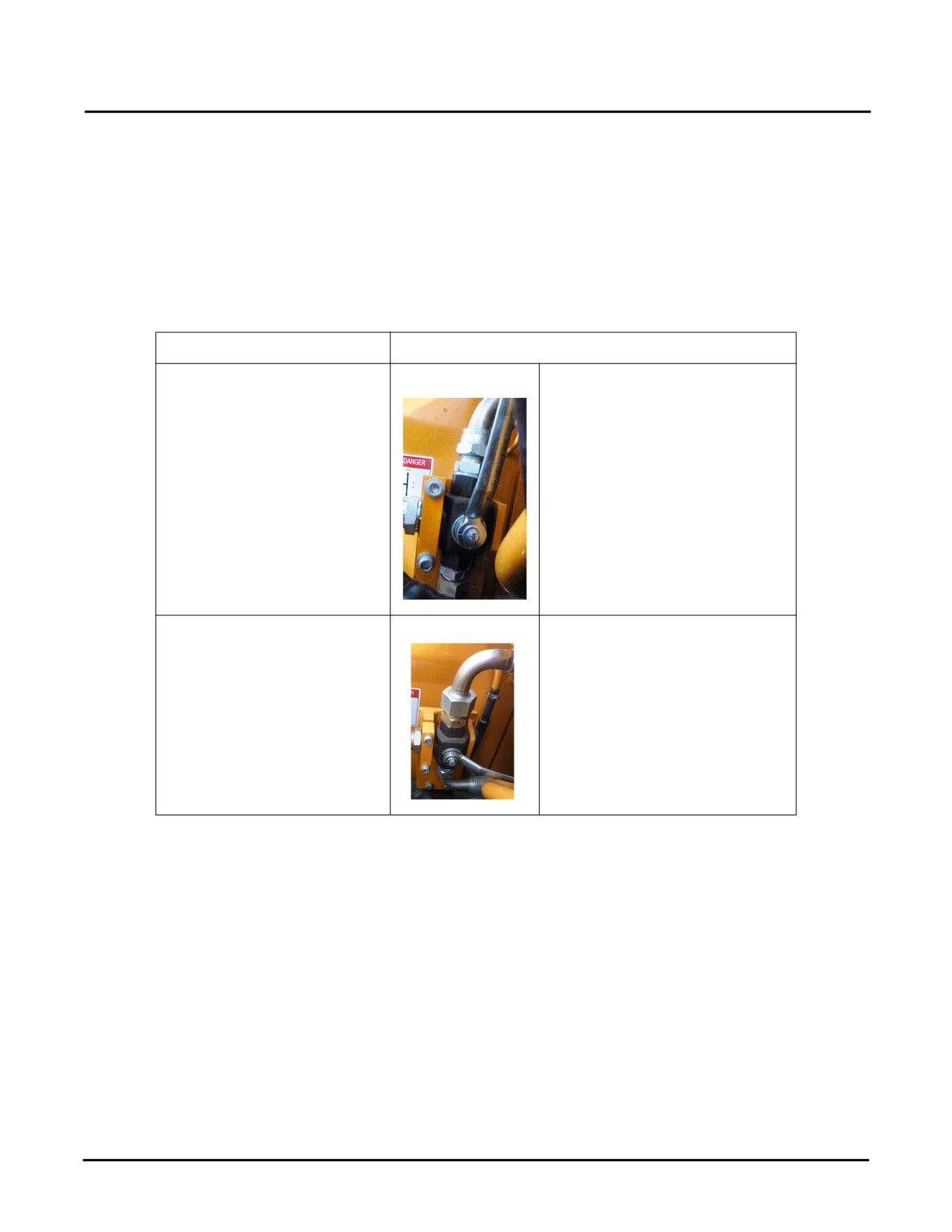
Attachment
Selector Valve Setting
One-way hydraulic attachment
Handle is straight up.
(e.g. breaker)
(As per attachment manufacturer’s
specifications. Contact Sany
America’s representative for
adjustment.)
Dual-action hydraulic attach-
Handle is parallel to the ground.
ment (e.g. shears)
(As per attachment manufacturer’s
specifications. Contact Sany
America’s representative for
adjustment.)
8-6
Safety, Operation & Maintenance Manual — November 28, 2013
SY335 Excavator
Optional Equipment System Functions
Optional Tool Selection
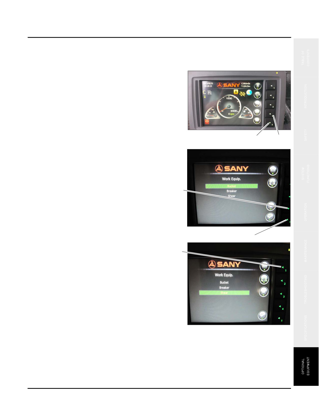
Select the tool to be used (bucket, breaker, shear) per the following steps.
1. Go to the monitor in the cab and press button 5 to
display the Main Menu screen.
2. Press button 4 until Tools icon (a) is highlighted, then
press button 5.
NOTE: The Work Equipment screen displays.
Fig. 8-5
5
4
3. Press button 4 until the tool to be used (bucket, breaker,
shear) is highlighted. Press button 5 to select that tool.
4
Fig. 8-6
5
4. Press button 1 to display the Main Menu.
1
Fig. 8-7
Safety, Operation & Maintenance Manual — November 28, 2013
8-7
Optional Equipment System Functions
SY335 Excavator
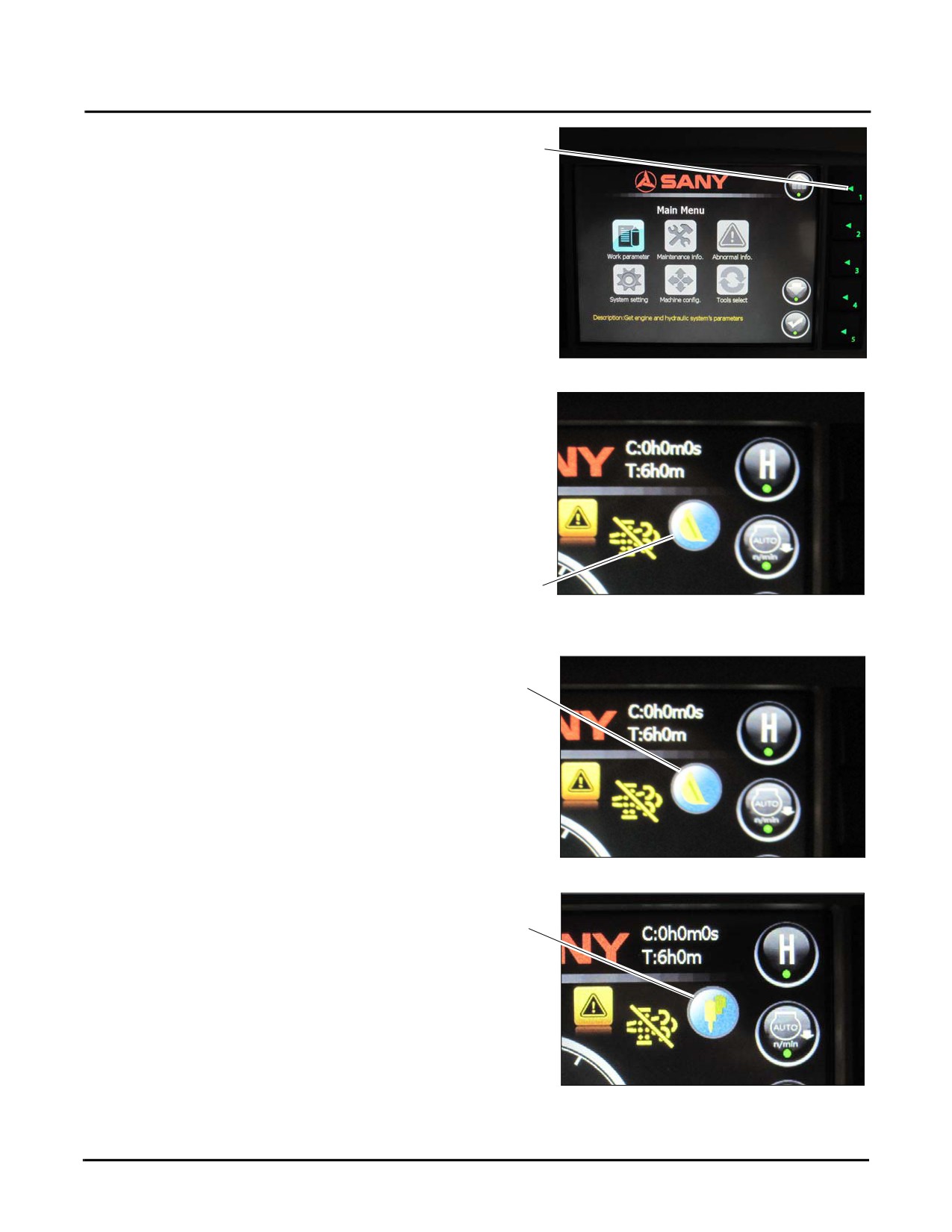
5. Press button 1 again to display the Main screen.
1
Fig. 8-8
6. Verify that the icon shown at (b) is the one selected on
the Work Equip. screen.
b
Fig. 8-9
•
Bucket (c)
c
Fig. 8-10
•
Breaker (d)
d
Fig. 8-11
8-8
Safety, Operation & Maintenance Manual — November 28, 2013
SY335 Excavator
Optional Equipment System Functions
•
Shear (e)
e
Fig. 8-12
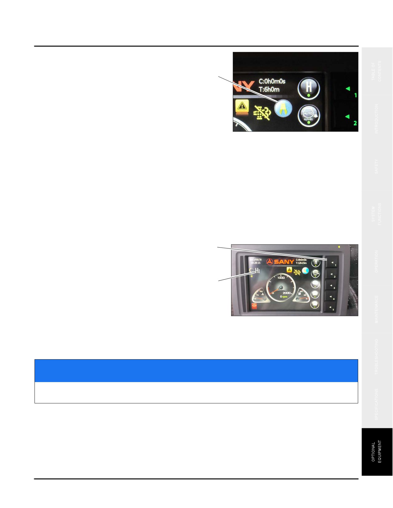
Depending upon the tool selected the working mode of the machine must now be changed as well. There are four
different working modes available, they are:
•
S: Standard duty: Used for normal excavating.
•
H: Heavy duty: Used for excavating in hard or rocky ground.
•
L: Light duty: Used for light tasks such as digging in soft soil.
•
B: Breaker mode
7. To chose the appropriate mode press button 1. The
1
mode selected is shown in the icon (f) at the upper left
of the screen.
NOTE: The modes cycle through H - S - L - B.
f
Fig. 8-13
NOTICE
Failure to set the machine in the proper working mode may result in degraded performance of
the optional tool or damage the machine.
Safety, Operation & Maintenance Manual — November 28, 2013
8-9
Optional Equipment Operation
SY335 Excavator
OPTIONAL EQUIPMENT OPERATION
Attach Optional Equipment
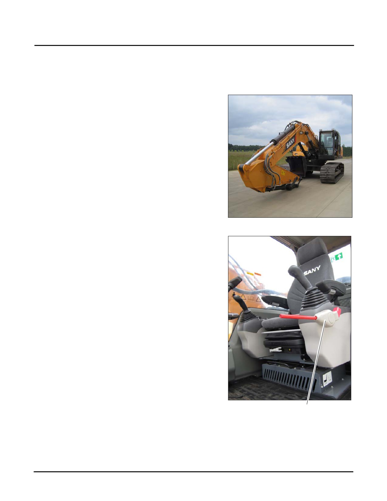
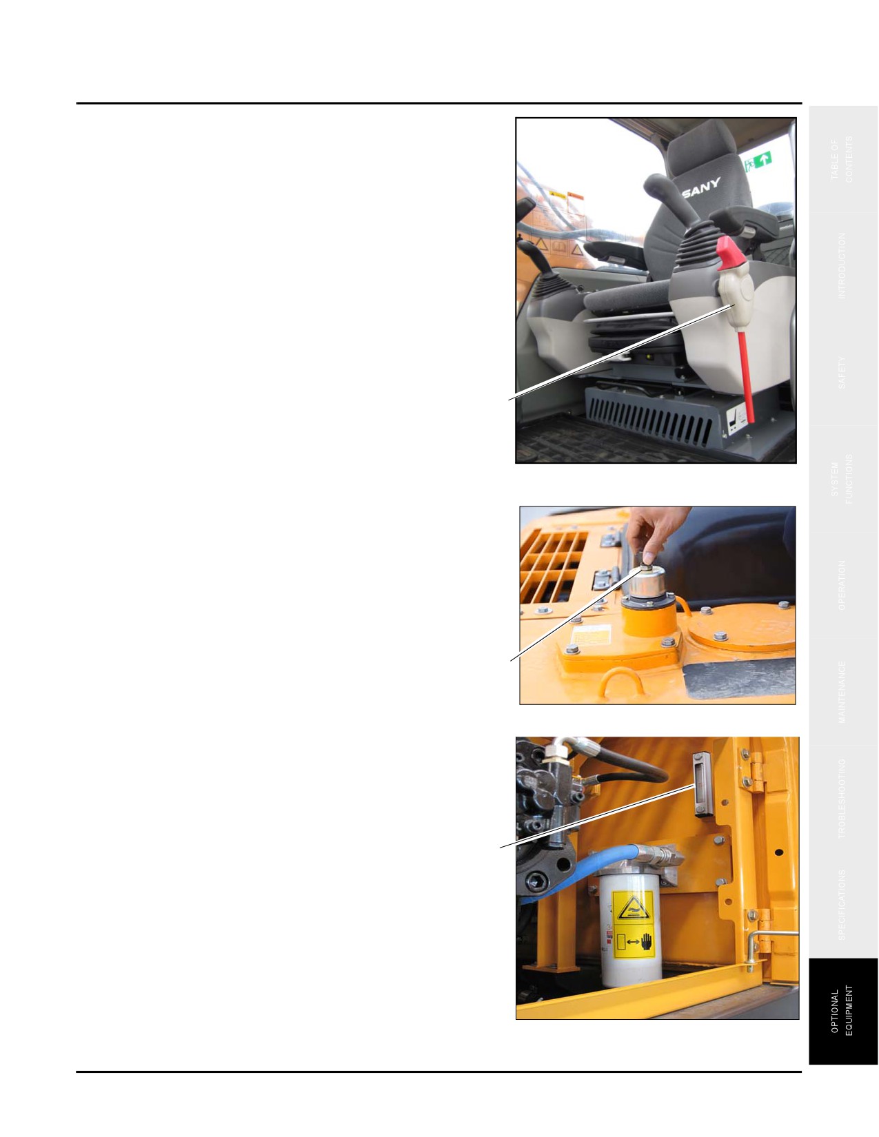
1. Lower the work equipment to the ground and shut down
the engine.
Fig. 8-14
2. Turn the start switch to ON position, and place the
hydraulic lockout control to the FREE position (a).
3. Fully cycle each control lever and control buttons for 2-
3 times within 15 seconds in order to release the internal
pressure remained in the hydraulic lines.
Fig. 8-15
a
8-10
Safety, Operation & Maintenance Manual — November 28, 2013
SY335 Excavator
Optional Equipment Operation
4. Place the hydraulic lockout lever to the LOCKED
position (b).
b
Fig. 8-16
5. Release the pressure completely by turning and opening
the butterfly nut on the breather valve [c] and pressing
the relief button to release the pressure.
c
Fig. 8-17
6. Check the temperature of hydraulic fluid (d) on the side
of the hydraulic tank.
NOTE: See “Hydraulic Oil Level” on page 4-15.
d
Fig. 8-18
Safety, Operation & Maintenance Manual — November 28, 2013
8-11
Optional Equipment Operation
SY335 Excavator
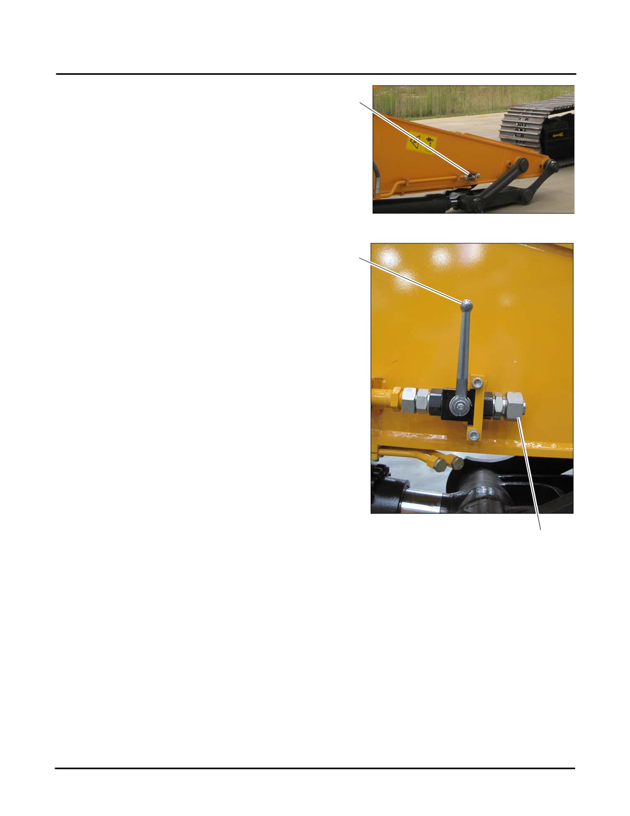
7. Go to the stop valve (e) located on the side of the
machine arm.
e
Fig. 8-19
8. Ensure that the stop valve (f) is in the locked position.
f
g
Fig. 8-20
9. Remove the screw cap (g) from the end of the stop
valve line.
NOTE: The disassembled parts should not be lost or damaged.
10. Connect the optional equipment lines in accordance with the manufacturer’s instructions.
NOTE: Connection sizes and additional accumulator may vary according to different optional equipment
manufacturers. Please consult 's authorized dealer in this regard.
11. Move the valves on the arm in accordance with the type of equipment used per the instructions shown in
Hydraulic Circuit page 8-6.
8-12
Safety, Operation & Maintenance Manual — November 28, 2013
SY335 Excavator
Optional Equipment Operation
Optional Equipment Control
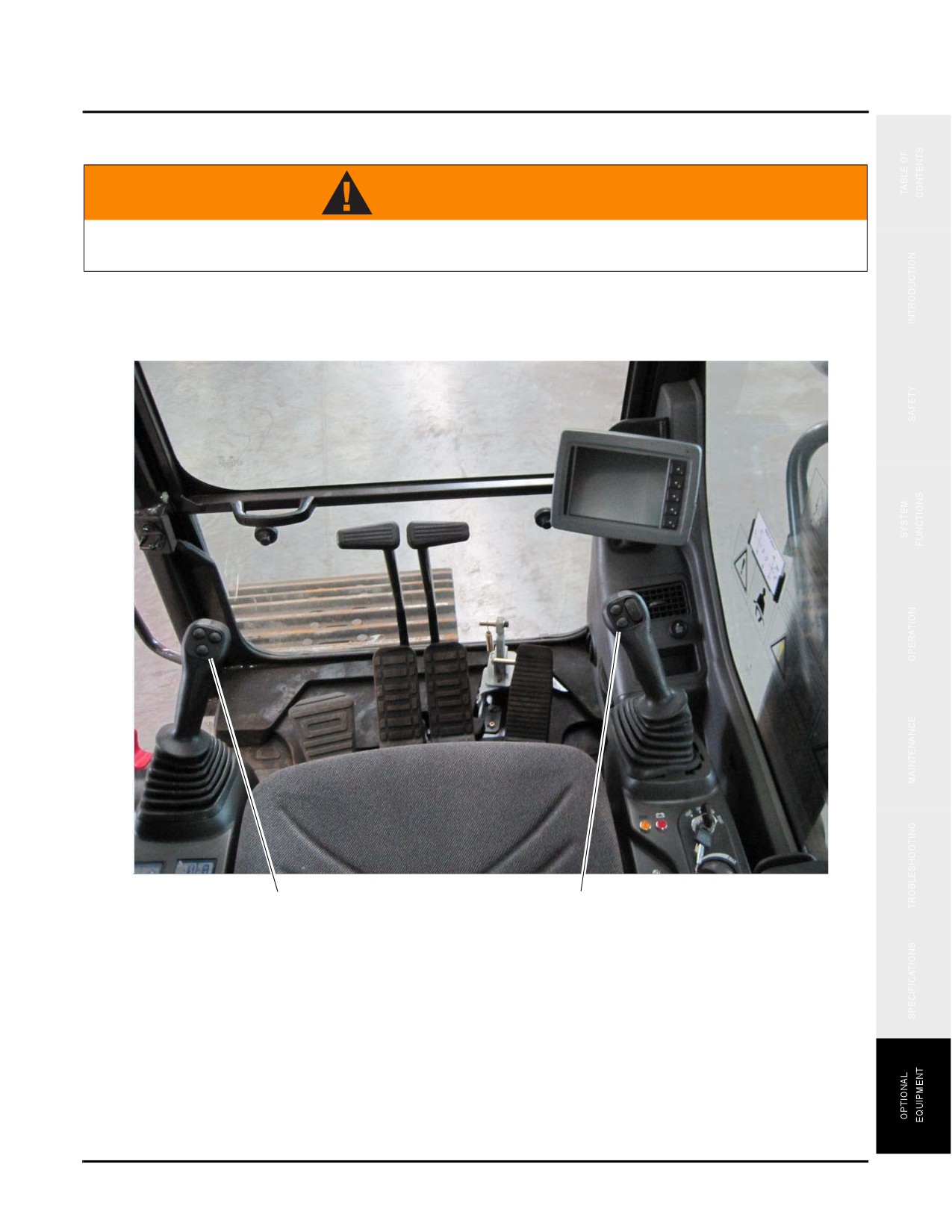
WARNING
Keep your thumbs off the control buttons on top of the joysticks when your are not operating
the attachments. Inadvertent movement of attachments may cause serious injuries or death.
Control switch and buttons on top of the left (a) and right (b) joysticks are used to control attachment operation.
a
b
Safety, Operation & Maintenance Manual — November 28, 2013
8-13
Optional Equipment Operation
SY335 Excavator
Hydraulic Breaker Controls
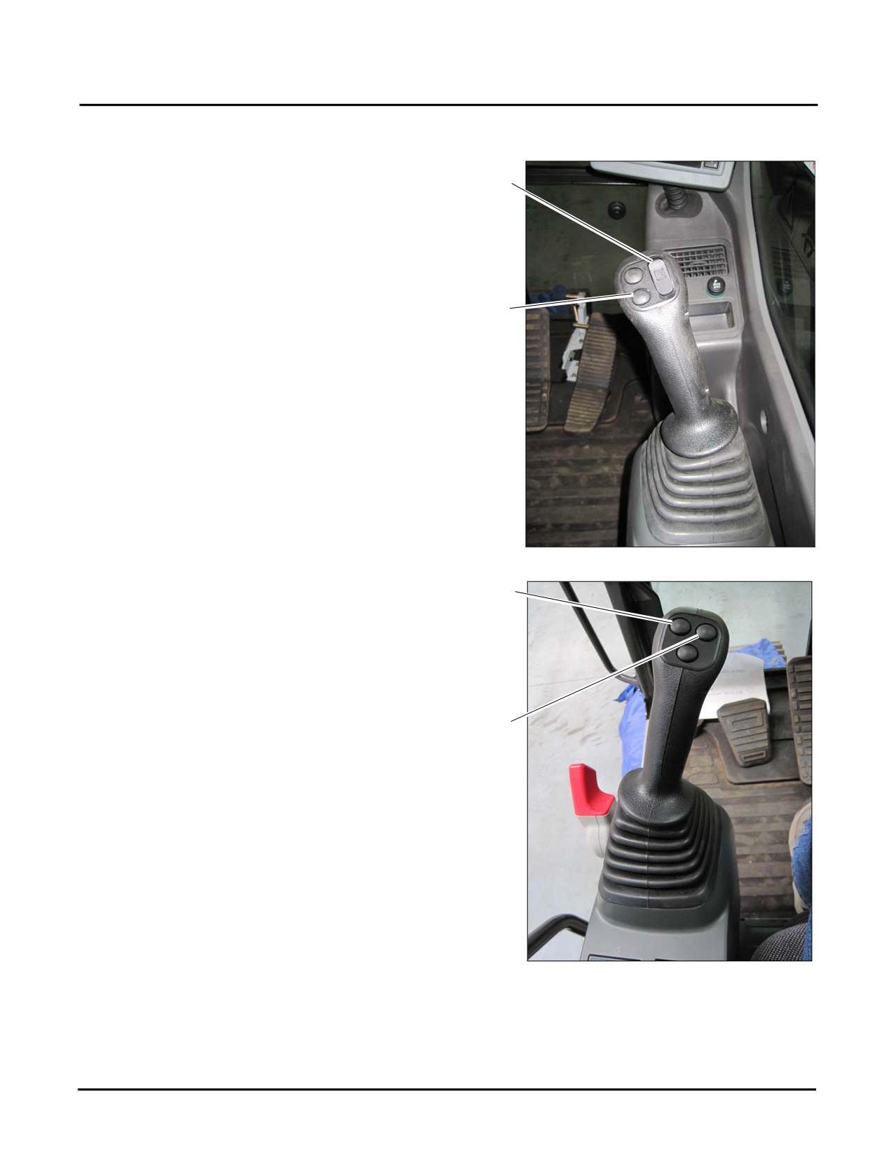
Attachment control switch (a) on the right joystick is used to
control a hydraulic breaker. Press upper part of this switch
a
to operate the breaker. Release this switch to stop the
breaker.
Hydraulic Shears Controls
1. Press the upper part of switch (a) on the right joystick to
b
open the shear and press the lower part to close the
shear.
NOTE: A backup button (b) is designed for future use
when other attachments are installed. For
control method of other attached tools, consult
the maker of the attachment and the machine
before installation.
Fig. 8-21
2. Buttons (c) and (d) on the left joystick are used to swing
c
the shears.
NOTE: Press button (c) to swing the shear to the left.
Press button (d) to swing the shear to the
right.
d
Fig. 8-22
8-14
Safety, Operation & Maintenance Manual — November 28, 2013
SY335 Excavator
Optional Equipment Operation
Disconnecting Optional Equipment
1. Lower the work equipment to the ground and shut down
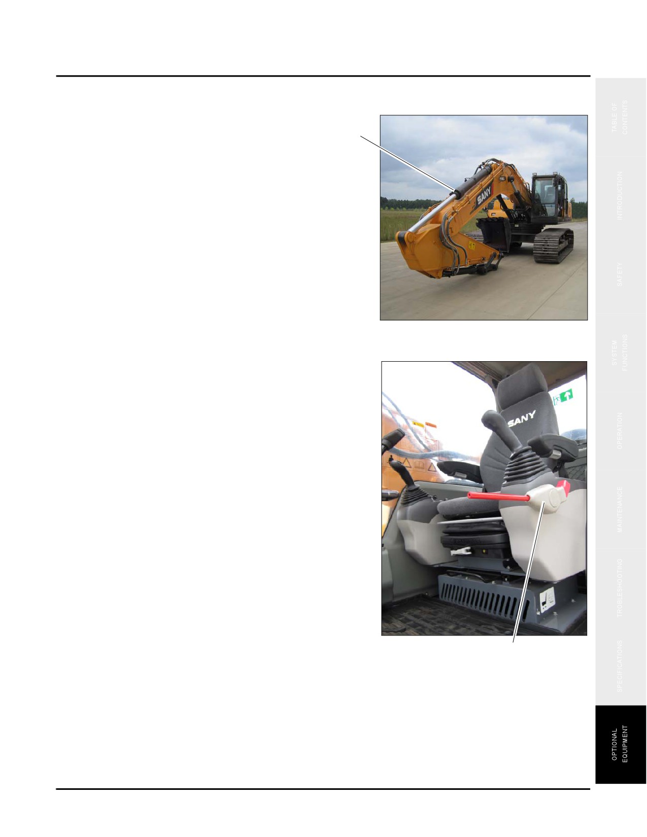
the engine (a).
a
Fig. 8-23
2. Turn the start switch to ON position, and place the
hydraulic lockout control to the FREE position (b.
3. Fully cycle each control lever and control buttons for 2-
3 times within 15 seconds in order to release the internal
pressure remained in the hydraulic lines.
Fig. 8-24
b
Safety, Operation & Maintenance Manual — November 28, 2013
8-15
Optional Equipment Operation
SY335 Excavator
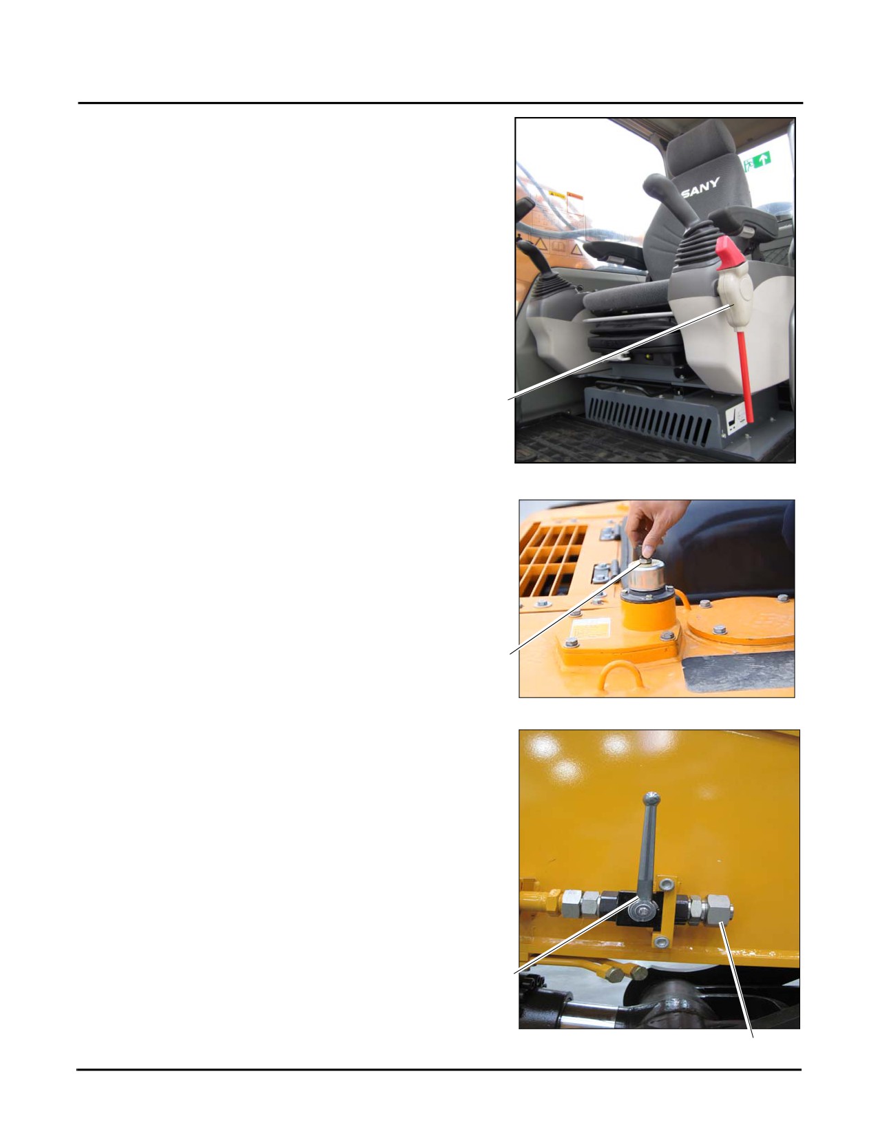
4. Place the hydraulic lockout lever to the LOCKED
position (c).
c
Fig. 8-25
5.
To release the pressure completely, turn and open the
butterfly nut on the breather valve [d] and press the
relief button to release the pressure.
6.
Check the temperature of hydraulic fluid (d) on the side
of the hydraulic tank.
d
NOTE: See “Hydraulic Oil Level” on page 4-15.
Fig. 8-26
7.
Turn the handle of the stop valve (mounted to the inlet
and outlet lines to the side of the arm) to LOCK position
(e).
NOTE: LOCK position stops flow of hydraulic oil.
(The line is perpendicular to arm length).
8.
Disconnect the hose at the side of the attachment and
install the screw caps (f) to the two outlets.
NOTE: The screw caps are used to avoid intrusion of
foreign objects.
9.
Remove the two installation pins and disassemble the
e
attachment.
Fig. 8-27
f
8-16
Safety, Operation & Maintenance Manual — November 28, 2013