SANY Crawler Hydraulic Excavator SY365H-9, SY365BH-9. Shop Manual (2014) - page 32
 

  Index      Manuals     SANY Crawler Hydraulic Excavator SY365H-9, SY365BH-9. Shop Manual (2014)


Search            copyright infringement  


Content      ..     30      31      32      33     ..


SANY Crawler Hydraulic Excavator SY365H-9, SY365BH-9. Shop Manual (2014) - page 32


8-45

Disassembly and Assembly

SY365(B)H-9 Crawler Hydraulic Excavator

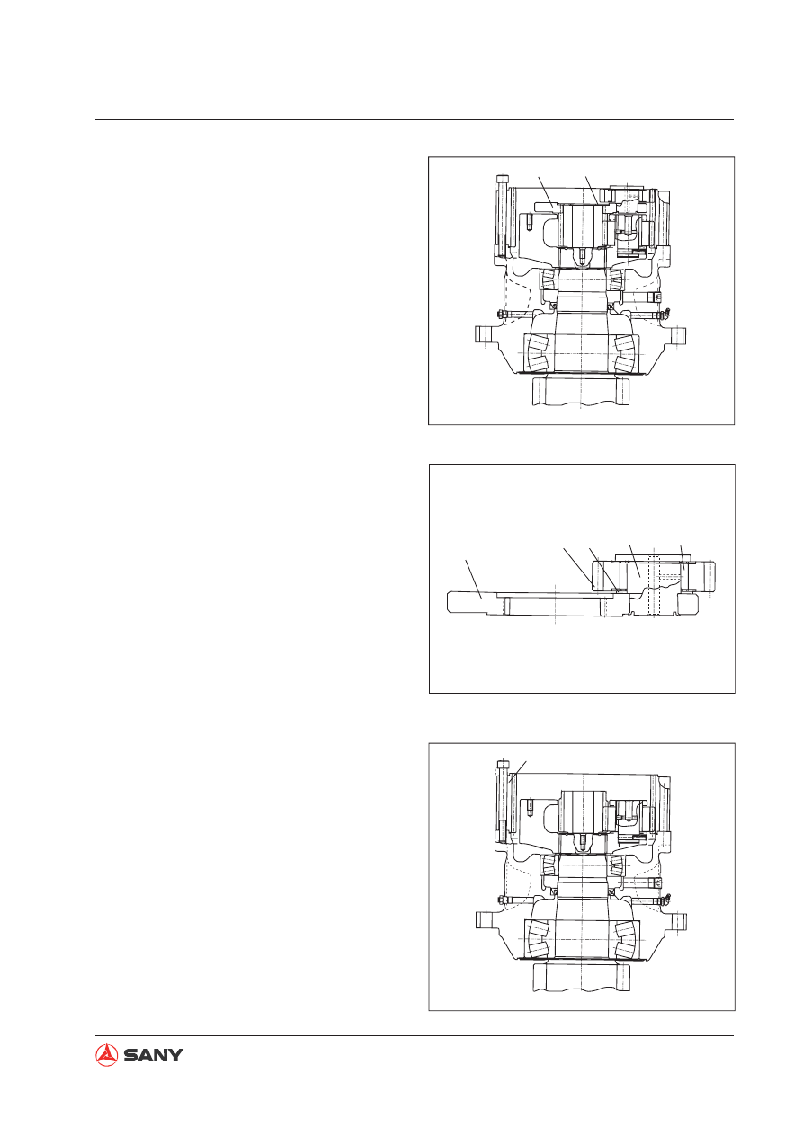
4. No.1 planetary carrier assembly

A.  Remove No.1 carrier assembly (3) and

the plate (4). 

B.  Disassemble No.1 carrier assembly. 

Cut the rivets on the shaft (8) to re-
move the shaft (8), and remove in turn 
the gear (6), bearing (9) and plate (7). 

5. Gear ring

Unscrew the mounting bolts to remove the
gear ring (10).

Fig. 8-78 

3

4

ZX335-1006068

5

6

7

8

9

ZX335-1006069

10

ZX335-1006070

Fig. 8-79 

Fig. 8-80 

8-46

Disassembly and Assembly

SY365(B)H-9 Crawler Hydraulic Excavator

11

ZX335-1006071

12

ZX335-1006072

6.  No.2 sun gear

Remove No.2 sun gear (11). 

7.  No.2 planetary carrier assembly

A.  Remove No.2 carrier assembly (12). 

Fig. 8-81 

Fig. 8-82 

8-47

Disassembly and Assembly

SY365(B)H-9 Crawler Hydraulic Excavator

20

ZX335-1006074

8. Snap ring

Remove the snap ring (20).

9. Disassembling the main shaft

A.  Place the shaft housing assembly on a

press and push the shaft assembly (21) 
out of the shaft housing assembly (22). 

B.  Disassemble No.2 carrier assembly 

with hands through the following steps.

a. Hammer the pin (13) in the shaft (14)

in order to push the shaft (14) out of
the carrier assembly (19).

Hammer out the pin (13) after removing
the shaft.

b. Remove the thrust washer (16) and

gear (17).

c. Insert the pin (15) to remove the

bearing (18) from the shaft. Remove
the pin (15).

19

13

14

17

18

15

16

ZX335-1006073

Fig. 8-83 

Fig. 8-84 

Push

21

22

ZX335-1006075

Fig. 8-85 

8-48

Disassembly and Assembly

SY365(B)H-9 Crawler Hydraulic Excavator

26

27

25

ZX335-1006077

B.  Disassemble the shaft assembly in the 

following procedure.

Remove the bearing (23) from the shaft 
(24). 

10. Bearing 

Remove the bearing (25) and the oil seal 
(26) from the housing (27). 

Push

23

24

ZX335-1006076

Fig. 8-86 

Fig. 8-87 

8-49

Disassembly and Assembly

SY365(B)H-9 Crawler Hydraulic Excavator

8.13.2 Assembly


Clean all the parts and check for any con-
tamination or damage. Apply engine oil to 
the sliding surfaces of the parts. 

1. Bearing

Press the bearing (23) into the housing (27). 

2. Oil seal

Press the oil seal (26) into the housing (27). 

  Oil seal mounting surface: gasket 

sealant (Loctite 515)

3. Housing assembly

A.  Position the plate (28) on the shaft (24). 

B.  Position the housing assembly (22) on 

the shaft (24). Press to 

fi

 t the bearing. 

Fig. 8-88 

Fig. 8-89 

Fig. 8-90 

23

27

ZX335-1006078

27

26

ZX335-1006079

24

22

28

ZX335-1006080

8-50

Disassembly and Assembly

SY365(B)H-9 Crawler Hydraulic Excavator

22

25

ZX335-1006081

4. Bearing

Press to 

fi

 t the bearing (25).

When press-fitting the bearing, press
the bearing inner race and outer race
simultaneously. Never press only the
inner race.

After assembling the bearing, check if
the housing rotates freely.

5. No.2 Planetary carrier assembly

Reassemble No.2 carrier assembly through
the following steps.

A.  Assemble the plate (16) in the carrier

assembly (19). 

B.  Assemble the gear (17) in the carrier 

assembly (19). Put the bearing (18) 
on the shaft (14). Slightly tap the pin 
(15) into the bore after alignment. Use 
a rubber hammer to tap the pin. Make 
sure that the pin (15) must not be 
higher than the bearing (18).

C.  Push the shaft assembly into the car-

rier assembly (19). Be careful not to 
damage the gear and the plate. Align 
the pin hole of the shaft with that of the 
carrier assembly, and install the pin 
(13). Carefully tap the pin with a rubber 
hammer during installation. 

Installation of the shaft requires rotat-
ing the planetary gear. Take care not to
damage the thrust washer.

19

13

14

17

18

15

16

ZX335-1006073

Fig. 8-91 

Fig. 8-92 

8-51

Disassembly and Assembly

SY365(B)H-9 Crawler Hydraulic Excavator

6.  Assemble in turn the snap ring (20),  No.2 

carrier assembly and No.2 sun gear (11). 

7.  Installation of gear ring

Apply sealant on the mating surface 
indicated by (C) and tighten it with screws. 
Never get the sealant onto the gear ring 
(10).

 Mating surface: Sealant (Loctite 515)

8.  No.1 planetary carrier assembly

A.  No.1 carrier assembly is assembled as 

the following. 

a.  Install the plate (7) on the carrier 

assembly (5). 

b.  Install the gear (6) onto the plate 

after installing the bearing (9) into 
the gear. 

c.  Press the shaft (8) into the gear (6) 

and the carrier assembly (5). Rivet 
one end of the shaft. 


Check if the gear rotates freely. 

11

No.2 planetary 
carrier

20

ZX335-1006082

Fig. 8-93 

Fig. 8-94 

Fig. 8-95 

10

c

ZX335-1006083

5

6

7

8

9

ZX335-1006069

8-52

Disassembly and Assembly

SY365(B)H-9 Crawler Hydraulic Excavator

B.  Install No.1 carrier assembly (3) and 

the plate (4). 

9. No.1 sun gear assembly

Install No.1 sun gear (2).

3

4

ZX335-1006068

2

ZX335-1006067

Fig. 8-96 

Fig. 8-97 

8-53

Disassembly and Assembly

SY365(B)H-9 Crawler Hydraulic Excavator

10.  Installation of swing motor assembly

Install the swing motor assembly after ap-
plying sealant to the mating surfaces of the 
gear ring and the motor cover. 

 Mating surface: sealant (Loctite 

515)

  Swing motor assembly: 55 kg

 Mounting bolts (swing motor):

156

±

5 Nm {16

±

0.5 kg}


The 14 bolt holes of the swing motor 
and swing drive assembly are distribut-
ed nonuniform. The mating direction of 
each hole is exclusive, as shown in the 
illustration on the right. The installation 
of swing motor requires proper align-
ment of the bolt holes in order to ensure 
the installation orientation. 

11. Re

fi

 lling of lubricant

Screw on the drain plug and re

fi

 ll lubricant 

through the 

fi

 ller to the speci

fi

 ed level (the 

upper mark of oil stick).

           Swing drive case: About 4 L

ZX335-1006084

Fig. 8-98 

8-54

Disassembly and Assembly

SY365(B)H-9 Crawler Hydraulic Excavator

13

9

3

2

1

6

11

8

12

10

7

5

4

ZX335-1006085

4

6

5

7

6

ZX335-1006086

9 10

4

5

7

8

ZX335-1006087

8.14 Idler AS 

8.14.1 Disassembly

1.  Remove the dowel pin (1) and the support 

(2). 

2.  Remove the floating seals (3) from the 

support (2) and the idler (4). 

3.  Remove the O-ring (11). Remove the idler 

(4) from the shaft (5) and the support as-
sembly (7).              


The idler contains 80 ml oil, which 
should be drained completely before 
disassembling. Spread a cloth on the 

fl

 oor to prevent smearing of the 

fl

 oor by 

the oil. 

4. Remove the 

fl

 oating seals (6) on the other 

side from the idler (4), shaft (5) and sup-
port assembly (7). 

5.  Remove the dowel pin (8) in order to 

remove the support (7) from the shaft (5). 

6.  Remove the bushings (9) and (10) from the 

idler (4). 

Fig. 8-99 

Fig. 8-100 

Fig. 8-101 

8-55

Disassembly and Assembly

SY365(B)H-9 Crawler Hydraulic Excavator

4

4

9

10

ZX335-1006088

910

4

5

7

8

ZX335-1006087

8.14.2 Assembly

1. Install the bushings (9) and (10) in the idler

(4).

2. Assemble the O-ring. Use the dowel pin (8)

to install the support (7) on the shaft (5).

3. Install the 

fl

 oating seals (6) on the idler (4),

shaft (5) and support (7) assembly.

Floating seals

Completely remove the grease from
the contact surfaces (hatched area in
the illustration on the right) of O-ring
and floating seal before installing the

fl

 oating seal. In addition, care must be

taken to keep the contact surface of

fl

 oating seal free from dust.

Fig. 8-102 

Fig. 8-103 

Fig. 8-104 

6

ZX335-1006089

8-56

Disassembly and Assembly

SY365(B)H-9 Crawler Hydraulic Excavator

7

5

4

ZX335-1006091

After installation of the floating seals,
check that the sealing inclination should
be less than 1 mm and the seal protru-
sion  be within a range of 5-7 mm.

4. Install the shaft (5) and support (7) assem-

bly to the idler (4).

Fig. 8-105 

a

ZX335-1006090

Fig. 8-106 

8-57

Disassembly and Assembly

SY365(B)H-9 Crawler Hydraulic Excavator

13

9

3

2

1

6

11

8

12

10

7

5

4

ZX335-1006085

6.  Install the O-ring. Use the dowel pin (1) to 

install the support (2). 

7. Re

fi

 ll oil and screw on the plug. 

 Oil: About 80 ml (No.18 hyperbola 

gear oil)

 Plug: 205.8

±

49 Nm {21

±

5 kgm}

3

ZX335-1006093

Fig. 8-107 

5.  Install the floating seal (3) to the idler (4) 

and support (2). 


Apply oil to the sliding surface of 

fl

 oat-

ing seal. Care must be taken to keep 
the sliding surface from any contami-
nants or dust. 


Remove the oil and dust from the con-
tact surfaces of the O-ring and 

fl

 oating 

seal. 

4

3

3

2

ZX335-1006092

Fig. 8-108 

Fig. 8-109 

8-58

Disassembly and Assembly

SY365(B)H-9 Crawler Hydraulic Excavator

1

ZX335-1006094

8.15  Sprocket 

8.15.1 Removal

1.  Remove the track assembly. For more 

information see

 “Track AS” on page 8-59

2.  Swing the work equipment 90

°

and lift the 

chassis with the help of the work equip-
ment. Place a block 

 between the track 

frame and the track shoe. 

3.  Remove the sprocket (1). 

  Sprocket: 98.4 kg

8.15.2 Installation


Installation is performed in the reverse pro-
cedure of removal. 


 Threads (bolt - sprocket):

Thread sealant (Kesaixin 1277). 

 Bolts (sprocket):

927

±

103 N·m {94.6

±

10.5 kgf·m}

Fig. 8-110 

8-59

Disassembly and Assembly

SY365(B)H-9 Crawler Hydraulic Excavator

M

2

ZX335-1006096

ZXT335-1006095

1

8.16  Track AS 

Special tools

Mark

Part Name

Necessity Qty

M

Manual/electric hydraulic 
track removing/installing 
machine

1

8.16.1 Removal

1.  Choose a place that has enough space to 

spread the track. Park the machine when 
the master pin is between the idler and the 
carrier roller. 

2.  Lower the work equipment. Loosen the 

grease 

fi

 tting (1) and release the track ten-

sion. 

3.  Pull out the master pin (2) with the tool (M). 

  WARNING


The adjustment cylinder is under ex-
tremely high pressure. Never loosen the 
grease fitting by more than one turn. 
Move the machine back and forth if no 
grease is seen. 

Fig. 8-111 

Fig. 8-112 

8-60

Disassembly and Assembly

SY365(B)H-9 Crawler Hydraulic Excavator

3

ZX335-1006097

ZX335-1006098

R

R

R

Corner

Corner

Corner

Track shoe nut
(Square)

Seat surface 
Must be in 
Close contact.

4.  Remove the tool (M). Move the machine 

forward so that the temporary pin 

 is in 

front of the idler. Place the block 

5.  Remove the temporary pin 

 and the 

dust seal. Move the machine backward to 
spread the track (3). 

8.16.2 Installation


Installation is performed in the reverse pro-
cedure of removal. 

See

 “Track Tensioner - Test and Adjust” on 

page 6-21


Installation procedure of track shoe bolts 
and nuts

A.  Bring the R side of the track shoe nut 

(1) to the link seat surface. Both seat 
surfaces should be in close contact 
when assembling the track shoe. 


If the track shoe bolts are installed 
from the other side, the corner of nut 
will interfere with the link seat surface, 
causing the nut to raise and the bolt to 
loosen. 

B.  Tighten the bolts of track shoe to the 

torque below. 

 Track shoe bolts: 

1029

±

60 Nm {105

±

6 kgm}

Fig. 8-113 

Fig. 8-114 


Content      ..     30      31      32      33     ..