SANY Crawler Hydraulic Excavator SY365H-9, SY365BH-9. Shop Manual (2014) - page 30
 

  Index      Manuals     SANY Crawler Hydraulic Excavator SY365H-9, SY365BH-9. Shop Manual (2014)


Search            copyright infringement  


Content      ..     28      29      30      31     ..


SANY Crawler Hydraulic Excavator SY365H-9, SY365BH-9. Shop Manual (2014) - page 30


8-13

Disassembly and Assembly

SY365(B)H-9 Crawler Hydraulic Excavator

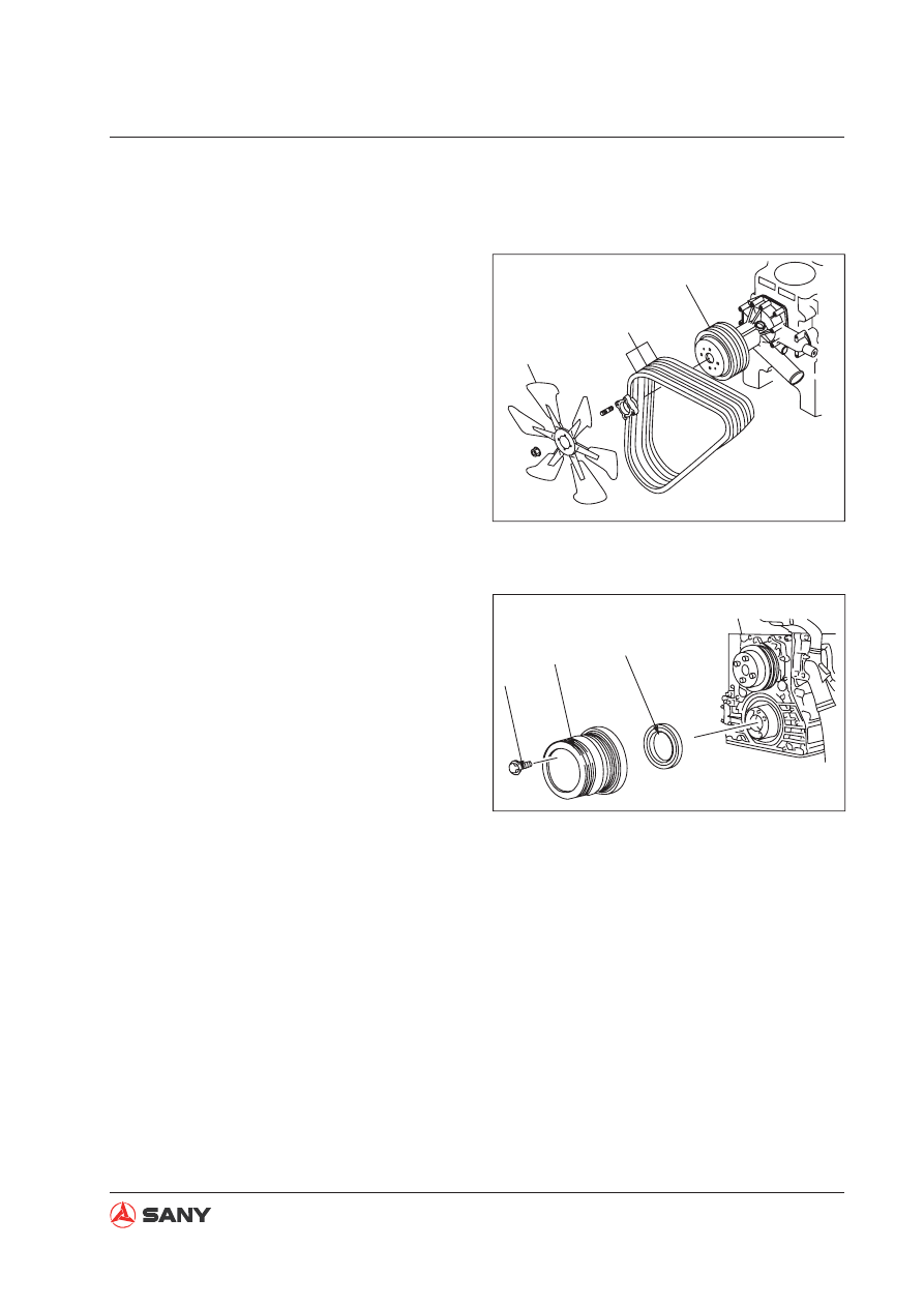
8.5  Engine Front Oil Seal 

8.5.1 Removal

1.  Remove the radiator assembly. See


“Radiator AS” on page 8-20.

2.  Remove the engine fan (1), belt (2) and 

pulley (3).

3.  R e m o v e   t h e   b o l t   ( 4 )   a n d   t h e n   t h e 

8.5.2 Installation


Installation is performed in the reverse pro-
cedure of removal.

crankshaft belt pulley (5).

4.  Remove the front oil seal (6).

3

2

1

ZX335-1006007

4

5

6

ZX335-1006008

Fig. 8-7 

Fig. 8-8 

8-14

Disassembly and Assembly

SY365(B)H-9 Crawler Hydraulic Excavator

2

ZX335-10

Sealant

ø2mm

Line

ZX335-1006010

8.6  Engine Rear Oil Seal 

8.6.1 Removal

1.  Remove the hydraulic pump assembly. 

See

 “Hydraulic Pump AS” on page 8-80. 

2. Remove the 

fl

 ywheel (1). 

3.  Remove the rear oil seal (2). 

8.6.2 Installation


Installation is performed in the reverse pro-
cedure of removal.


Install the rear oil seal as the following:

A.  Apply engine oil to the lip of rear oil 

seal.

B.  Clean the seal surface.

C.  Apply sealant along the sealing line 

continuously and uniformly.

 Sealant (Tianshan 1596)

D.  Installation is to be performed within 

three (3) minutes after application of 
sealant. It is important to keep the ap-
plied sealant in proper area.

Fig. 8-9 

Fig. 8-10 

8-15

Disassembly and Assembly

SY365(B)H-9 Crawler Hydraulic Excavator

1. Drain coolant from the engine.

 Coolant: 26 L

2. Open the engine hood.

3. Remove the air intake hose (1).

4. Disconnect the lines (2) and (3) between

the fuel 

fi

 lter and the fuel injection pump.

5. Remove the fuel filter bracket (4) and the

fuel 

fi

 lter assembly (5).

ZXT335-1006011

ZXT335-1006012

1

ZXT335-1006013

2

5

4

3

8.7 Cylinder Head AS

8.7.1 Removal

NOTICE

Disconnect the cable from the negative
post (-) of the battery.

Fig. 8-11 

Fig. 8-12 

Fig. 8-13 

8-16

Disassembly and Assembly

SY365(B)H-9 Crawler Hydraulic Excavator

6.  Disconnect the six (6) fuel delivery lines (6).

7.  Remove the cover (7) of exhaust muffler 

connector.

8.  Disconnect the air intake hose (8).

9.  Disconnect the air intake hose (9) and the 

crankcase breathing hose (10) between 
turbocharger and intercooler.

ZXT335-1006014

6

ZXT335-1006015

7

8

9

10

Fig. 8-14 

Fig. 8-15 

8-17

Disassembly and Assembly

SY365(B)H-9 Crawler Hydraulic Excavator

11

13

12

ZX335-1006016

10. Disconnect the oil delivery line (11) and the oil return line (12). 

11. Remove the turbocharger system assembly.

12. Remove the exhaust manifold (13).

Fig. 8-16 

8-18

Disassembly and Assembly

SY365(B)H-9 Crawler Hydraulic Excavator

14. Remove the six (6) nozzle seats (16).

13. Remove the radiator inlet hose (14) and 

outlet hose (15). 


ZXT335-1006017

14

15

ZXT335-1006018

16

Fig. 8-17 

Fig. 8-18 

8-19

Disassembly and Assembly

SY365(B)H-9 Crawler Hydraulic Excavator

15.  Remove the rocker arm cover (17). 

16. Remove the camshaft assembly (18).

17. Remove the rocker arm assembly (19).

18. Remove the bolts of cylinder head and 

lift the cylinder head assembly in order to 
disassemble it.

19. Remove the cylinder head gasket (21).

ZX335-1006019

8.7.2 Installation


Installation is performed in the reverse pro-
cedure of removal.


 Rocker cover bolt:

7.8-9.8N.m{0.8-1.0kgf.m}

 Cylinder head bolt:

88N.m{9.0 kgf.m }+90

°

 Cylinder head bolt threads: engine oil

 Camshaft 

fl

 ange surface: engine oil

 Camshaft journal circumference: en-

gine oil


Adjusting valve clearance


See  “Valve Clearance - Adjust” on 
page 6-7. 


Adding coolant

Add engine coolant to the specific level. 
Start the engine to circulate coolant in or-
der to eliminate all foams. Check the cool-
ant level again.

Fig. 8-19 

8-20

Disassembly and Assembly

SY365(B)H-9 Crawler Hydraulic Excavator

8.8  Radiator AS 

8.8.1 Removal

1.  Open the engine hood

2.  Open the pressure cap (1). Drain engine 

coolant via the drain valve beneath the 
coolant tank.

Coolant: Approx.  26 L

3.  Disconnect the pipes from the hydraulic oil 

cooler delivery port (2) and supply port (3). 
Seal the ports in order to prevent the leak-
age of hydraulic oil in the hydraulic system.

4.  Drain hydraulic oil from the cooler and from 

radiator. 

Hydraulic oil radiator: Approx. 8 L

5.  Remove hose (4) of coolant tank.

ZXT335-1006020

1

ZXT335-1006021

2

3


ZXT335-1006022

4

Fig. 8-20 

Fig. 8-21 

Fig. 8-22 

8-21

Disassembly and Assembly

SY365(B)H-9 Crawler Hydraulic Excavator

7.  Remove the inlet and outlet air hoses (7) 

and (8) of the intercooler.

6.  Remove the inlet and outlet houses (5) and 

(6) of the water cooler.

Hydraulic oil radiator: Approx. 5.6 L

8.  Remove the four bolts (9) of the A/C radia-

tor. Remove the A/C radiator and put it in a 
suitable place.


ZXT335-1006023

6

5


ZXT335-1006024

7

8

ZXT335-1006025

9

Fig. 8-23 

Fig. 8-24 

Fig. 8-25 

8-22

Disassembly and Assembly

SY365(B)H-9 Crawler Hydraulic Excavator

9. Remove the radiator fan guard (10).

10. Remove the four bolts (11) from the bottom

of radiator.

11. Remove the bolts (12) and (13) of both left

and right brackets.

ZXT335-1006026

10

ZXT335-1006027

11

11

ZXT335-1006028

12

13

Fig. 8-26 

Fig. 8-27 

Fig. 8-28 

8-23

Disassembly and Assembly

SY365(B)H-9 Crawler Hydraulic Excavator

8.8.2 Installation

Installation is performed in the reverse pro-
cedure of removal.

Adjust the clearance (a) between the fan
and guard so that the clearance is uni-
form around the fan.

The clearance (a) should read as the fol-
lowing on the left, right, top and bottom
points.

Standard clearance (a) (around the
fan): 10 mm

Fan dia. (b): ø830 mm

Guard inner dia. (c): ø850 mm

Re

fi

 lling engine coolant and hydraulic oil

Refill engine coolant and hydraulic oil to
the speci

fi

 c levels. Start the engine to cir-

culate the coolant and oil. Check the cool-
ant level and oil level again.

           Engine coolant: Approx. 26 L.

           Hyd oil radiator: Approx. 8 L.

12. Install eyebolts (14) on both sides of the

radiator and lift the radiator assembly.

Before lifting the radiator assembly, move
the radiator assembly in axial direction until
the fan is free from the fan guard.

ZXT335-1006029

14

Fig. 8-29 

8-24

Disassembly and Assembly

SY365(B)H-9 Crawler Hydraulic Excavator

ZXT335-1006030

ZXT335-1006031

2

1

3

8.9  Engine and Hydraulic Pump AS 

8.9.1 Removal

Lower the work equipment to the ground in 
order to ensure safety. Stop the engine. Dis-
connect the cable from the battery negative (-) 
post. 

Loosen the butter

fl

 y nut on the breather valve 

and press the relief button to release internal 
pressure. 


Mark the lines to avoid mistakes during re-
installation. 

1.  Remove the hydraulic tank suction filter 

and block the opening. 

2.  Discharge engine coolant. 

  Coolant: About  22.9 L

3.  Open the engine hood. 

4.  Disconnect lines (1), (2) and (3). 

Fig. 8-30 

Fig. 8-31 

8-25

Disassembly and Assembly

SY365(B)H-9 Crawler Hydraulic Excavator

ZXT335-1006032

5

4

8

6

7

ZXT335-1006033

10

9

10

ZXT335-1006034

11

12

5.  D i s c o n n e c t   h o s e s   ( 4 ) ,   ( 6 )   a n d   ( 7 ) . 

Disconnect the cables (5) and (8) of main 
pump pressure sensors. 

6.  Remove the hose (9) and the clamps (10). 

7.  Remove the main pump negative feedback 

hoses (11) and (12). 

Fig. 8-32 

Fig. 8-33 

Fig. 8-34 

8-26

Disassembly and Assembly

SY365(B)H-9 Crawler Hydraulic Excavator

ZXT335-1006035

13

14

15

ZXT335-1006036

16

17

18

19

20

21

22

ZXT335-1006037

23

24

8.  Remove the main pump PSV hose (13), 

clamp (14) and cable (15).

9.  Disconnect the engine fuel hoses (16) and 

(17) and the engine oil hoses (18) and (19). 

10. Disconnect the engine speed sensor 

cables (20) and (21) as well as the clamp 
(22).

11. Unscrew the throttle guy connecting bolt 

(23) and the electronic shutdown device 
connecting bolt (24).

Fig. 8-35 

Fig. 8-36 

Fig. 8-37 

8-27

Disassembly and Assembly

SY365(B)H-9 Crawler Hydraulic Excavator

ZXT335-1006038

25

26

27

ZXT335-1006039

28

29

30

31

ZXT335-1006040

32

33

34

35

36

12. Remove the coolant temperature sensor, 

high temperature switch external cables 
(25) and (26) as well as the hose clamps 
(27).

13. Disconnect the compressor cables (28) 

and (29) as well as the hoses (30) and (31).  

14. Disconnect the external cable (32) of 

engine oil pressure sensor and the cable 
(33) of engine oil pressure sensor. 

15. Remove the clamps (34). 

16. Remove the starter main cable (35).  

17. Disconnect the alternator cable (36).

Fig. 8-38 

Fig. 8-39 

Fig. 8-40 

8-28

Disassembly and Assembly

SY365(B)H-9 Crawler Hydraulic Excavator

ZXT335-1006041

37

ZXT335-1006042

41

38

39

40

ZXT335-1006043

42

18. Remove the hose clamp (37). 

19. Disconnect the hoses (38), (39) and (40)

between the engine and the radiator.

20. Disconnect the air intake hose (41).

21. Disconnect the hose (42) between the 

engine and the radiator.

Fig. 8-41 

Fig. 8-42 

Fig. 8-43 


Content      ..     28      29      30      31     ..