SANY Crawler Hydraulic Excavator SY365H-9, SY365BH-9. Shop Manual (2014) - page 33
 

  Index      Manuals     SANY Crawler Hydraulic Excavator SY365H-9, SY365BH-9. Shop Manual (2014)


Search            copyright infringement  


Content      ..     31      32      33      34     ..


SANY Crawler Hydraulic Excavator SY365H-9, SY365BH-9. Shop Manual (2014) - page 33


8-61

Disassembly and Assembly

SY365(B)H-9 Crawler Hydraulic Excavator

a

ZX335-1006099


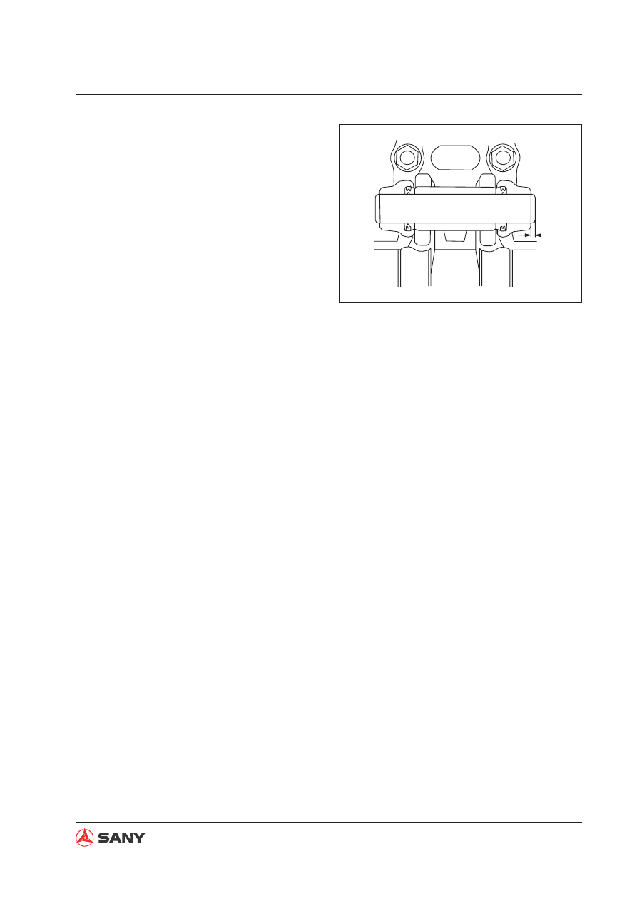
Use the tool (M) to press the master 
pin. Make sure that the protrusion of 
master pin meets the size (a). 

Master pin protrusion (a): 4.2

±

2mm


Before installing the dust seal, apply 
grease (G2-LI) to its contact surface 
with the bushing. 

Fig. 8-115 

8-62

Disassembly and Assembly

SY365(B)H-9 Crawler Hydraulic Excavator

1

ZXT335-1006100

2

ZXT335-1006101

8.17  Swing Bearing AS 

8.17.1 Removal

1. Remove the swing frame assembly. For

more information See 

“Swing frame AS”

on page 8-64

.

2. Remove the 36 bolts (1) in order to take off

the swing bearing assembly.

3. Lift the swing bearing assembly (2).

  Swing bearing assembly; 526 kg

Fig. 8-116 

Fig. 8-117 

8-63

Disassembly and Assembly

SY365(B)H-9 Crawler Hydraulic Excavator

8.17.2 Installation


Installation is performed in the reverse pro-
cedure of removal.


 Threads (bolt - swing bearing):

Thread adhesive (Tianshan 1277)

 Mounting bolts (swing bearing):

Step 1: 

Use a pneumatic spanner to tighten the 
bolts. 

Step 2: 

Tightened to: 

927

±

103 Nm {94.6

±

10.5 kgm}

A.  When a torque wrench is used to 

tighten the bolts, tighten first the four 
corners and then mark them. 

B.  Other bolts will be tightened clockwise 

or counterclockwise. After one bolt is 
tightened, tighten the next one on the 
diagonal position and make a mark. 

C.  Tighten the rest bolts in the same way. 


Let the S mark in the soft zone of the 
inner race of the inner ring face the 
right side, as shown in the photo, and 
install the swing bearing to the track 
frame. 


Apply grease to the inside of the gear 
ring of the swing bearing. 

All gear teeth must be covered by 
grease .

 Swing bearing: 

Grease(MoS

2

 G2-LI):15 L

Inner race
soft zone

ZXT335-1006102

Fig. 8-118 

8-64

Disassembly and Assembly

SY365(B)H-9 Crawler Hydraulic Excavator

ZXT335-1006104

2

ZXT335-1006103

1

8.18  Swing frame AS 

8.18.1 Removal

Fully extend the arm and the bucket. Lower 
the work equipment to the ground and engage 
the hydraulic lockout control. 

1.  Disassemble the work equipment assem-

bly. See

 “Work Equipment AS” on page 8-97

.     

2.  Remove the counterweight assembly.  See 

“Counterweight AS” on page 8-104

3.  Remove the four (4) hoses (1) of boom 

cylinder. 

Cork the hoses to stop oil 

fl

 owing out. 

4.  Lift the boom cylinder assembly (2).

5.  Remove the plate (3) and the pin (4). Lift 

Fig. 8-119 

Fig. 8-120 

8-65

Disassembly and Assembly

SY365(B)H-9 Crawler Hydraulic Excavator

ZXT335-1006105

4

3

ZXT335-1006106

5

7

6

the boom cylinder assembly (2) in order to 
disassemble it. 

Remove the boom cylinder assembly on 
the other side in the same way. 

  Boom cylinder AS: 264 kg

6. Remove the plate (5), air intake hose (6)

and fan guard (7).

Removal of the swing frame requires 
removing other parts that interfere with the 
lifting of swing frame. 

7. Disconnect the six (6) hoses over the

ZXT335-1006107

8

9

10

11

12

13

rotary joint assembly on the side of swivel 
joint. 

(8): Central swivel joint (port A)-

Left travel control valve (port BTL)

(9): Central swivel joint (port C)-

Left travel control valve (port ATL)

(10): Central swivel joint (port F)- 

       Solenoid valve

(11): Central swivel joint (port G)-

Swing motor (port T)

(12): Central swivel joint (port D)-

Right travel control valve (port ATR)

(13): Central swivel joint (port B)-

Right travel control valve (port BTR)

8. Remove the bolt (14).

9. Unscrew the 32 swing frame mounting

Fig. 8-121 

Fig. 8-122 

Fig. 8-123 

8-66

Disassembly and Assembly

SY365(B)H-9 Crawler Hydraulic Excavator

ZXT335-1006108

15

bolts in order to remove the swing frame 
assembly (15). Lift the swing frame as-
sembly off the machine. 


Remove the front and rear mounting 
bolts of the platform. Use a lever block 
to adjust the swing frame so that the 
platform can reach a balance  both 
longitudinally and laterally. Remove the 
last two bolts 

fi

 nally. 


Take care not to damage the central 

swivel joint assembly while removing 
the swing frame assembly. 

 Swing frame assembly: 

Model

Assembly (kg)

Only swing 

frame (kg)

SY365(B)H-9

14,755

3,040

8.18.2 Installation


Installation is performed in the reverse procedure of removal.


 Clamping screws (air intake hose):  5.4~6.4 Nm {0.55~0.65 kgm}


 Mating surface (swing bearing):  Flat surface sealant (Tianshan 1596)

 Threads (bolt - swing frame):  Thread adhesive: (Tianshan 1277)

 Mounting bolts (swing frame):

Step 1: Tighten the bolts with a pneumatic spanner.

 Step 2: tighten them again.     490~608 Nm {50~62 kgm}


Re

fi

 lling of hydraulic oil

Re

fi

 ll through the 

fi

 ller opening the hydraulic oil to the speci

fi

 ed level. Start the engine to circu-

late oil in the hydraulic system, and check the oil level again. 


Purging the air

Purge the air from the travel motor. See

 “Air in Each Component - Purge” on page 6-41.


8-67

Disassembly and Assembly

SY365(B)H-9 Crawler Hydraulic Excavator

ZXT335-1006109

1

2

ZXT335-1006110

5

4

3

6

7

8

8.19 Swivel Joint AS

8.19.1 Removal

Release remaining pressure in the hydraulic 
return circuit. See 

“Remaining Pressure in 

Hydraulic Lines - Relieve” on page 6-36

.


Tag each line so as to ensure correct rein-
stallation. 

1.  Disconnect the hoses (1) through (8) on 

the central swivel joint of the travel motor. 

(1)

Central swivel joint (port T) - 

Left travel motor (port T)

(2): Central swivel joint (port T) -

Right travel motor (port T)

(3): Central swivel joint (port B) -

Left travel motor (port PA)

(4): Central swivel joint (port D) -

Right travel motor (port PB)

(5): Central swivel joint (port A) -

Left travel motor (port PB)

(6): Central swivel joint (port C) -

Right travel motor (port PA)

(7): Central swivel joint (port E)-

Left travel motor (port X)

(8): Central swivel joint (port E) -

Right travel motor (port X)

Fig. 8-124 

Fig. 8-125 

8-68

Disassembly and Assembly

SY365(B)H-9 Crawler Hydraulic Excavator

ZXT335-1006112

a

b

15

16

16

ZXT335-1006113

17

2. Disconnect the hoses (7) through (12)

between:

(9): Central swivel joint  (port T) - 

Swing motor (port Dr)

(10): Central swivel joint (port E) -

Solenoid valve (port PT)

(11): Central swivel joint (port C) -

Left travel control valve (port BTL)

(12): Central swivel joint (port A) -

Right travel control valve (port ATL)

(13): Central swivel joint (port D) -  

Left travel control valve (port BTR)

(14) Central swivel joint (port B) - 

Right travel control valve (port ATR)

3. Remove the two(2) pin rolls (16) in order to

remove the plate (15).

4. Remove the four bolts (a) in order to

remove the plate (b).

5. Remove the four mounting bolts (17).

9

10

11

12

13

14

ZXT365-1308111

Fig. 8-126 

Fig. 8-127 

Fig. 8-128 

8-69

Disassembly and Assembly

SY365(B)H-9 Crawler Hydraulic Excavator

ZXT335-1006114

18

Sprocket

Central swivel joint

B D

A C

ZX335-1006115

6.  Remove the swivel joint assembly (18).                                    

  Central swivel joint: 45 kg

8.19.2 Installation


Installation is performed in the reverse pro-
cedure of removal. 


Install the central swivel joint facing the di-
rection indicated in the illustration. 

(In the illustration, the machine is viewed 
from the above.)


Re

fi

 lling of oil (hydraulic tank)

Re

fi

 ll through the 

fi

 ller opening the hydrau-

lic oil to the speci

fi

 ed level. Start the engine 

to circulate oil in the hydraulic system, and 
check the oil level again. 


Purging the air

Purge the air from the travel motor. See


“Air in Each Component - Purge” on 
page 6-41.

Fig. 8-129 

Fig. 8-130 

8-70

Disassembly and Assembly

SY365(B)H-9 Crawler Hydraulic Excavator

ZX335-1006117

Dust ring

Lip

Housing

8.20  Central Swivel Joint AS 

8.20.1 Disassembly

1. Remove the 

fi

 xing bolt (1). 

2.  Remove the cover (2).

3.  Remove the rotor (12) from the housing (6).


Take care not to damage the sliding 
surface of the seal of the rotor (12). 

4.  Remove the O-ring (3), oil seal (8) and 

retainer (7) from the housing (6). 

5.  Remove the rotary seal (9) and O-ring (10) 

from the housing (6).  

6.  Remove the oil seal (11) from the rotor (12). 

8.20.2 Assembly

1.  Install the oil seal (11) on the rotor (12). 


Let the lip face the dust ring of housing.

2.  Install the O-ring (10), rotary seal (9) in the 

housing (6). 

3.  Fix the rotor (12) on a work bench. Install 

the housing (6) on the rotor (12). 

The clearance between the housing (6) 
and the rotor (12) approximates 0.1 mm, 
so the rotor must be inserted slowly in the 
axial direction. Take care not to damage 
the rotary seal and the O-ring. 

4.  Use a rubber hammer to tap the housing (6) 

in order to match the rotor (12) properly. 

5.  Install the O-ring (3) and retainer (7) on the 

rotor (12). 

6.  Install the cover (2) and tighten the bolts 

(1). 

 Fixing bolts: 49 Nm {5 kgm}

ZX335-1006116

1

2

5

4

3

6

7

8

9

10

11

12

13

Fig. 8-131 

Fig. 8-132 

8-71

Disassembly and Assembly

SY365(B)H-9 Crawler Hydraulic Excavator

ZXT335-1006118

1

2

3

ZXT335-1006119

5

4

6

7

ZXT335-1006120

8

9

8.21 Hydraulic Tank AS 

8.21.1 Removal

1.  Drain oil from the hydraulic tank.          


 Hydraulic oil: About 260 L

2.  Open the engine hood. 

3.  Remove the engine hood (1), beam (2) 

and control valve cover (3). 

4.  Remove the covering (4) and the main 

pump partition (5).

5.  Remove the engine partition (6) and the 

bracket (7) at the hydraulic tank side.     

6.  Remove the two(2) oil return tubes (8) and 

(9) of the hydraulic tank.

Fig. 8-133 

Fig. 8-134 

Fig. 8-135 

8-72

Disassembly and Assembly

SY365(B)H-9 Crawler Hydraulic Excavator

ZXT335-1006121

10

11

12

13

14

15

16

ZXT335-1006122

17

18

19

7.  Remove the six hoses.                         


(10): Oil return (T-block, pilot)

(11): Oil return D2 (main valve)

(12) & (13): Oil return (leak of main pump)

(14): Oil return (solenoid valve)

(15): Oil return D1/D3 (main valve)

(16): Oil return (swing motor) 


Tag the hoses for identi

fi

 cation. 


Use socket nuts to protect the hose 
connectors and cone seals against 
damage.

8.  Disconnect the oil suction tube (17) from 

the bottom of hydraulic tank and the oil 
suction hose (18) connected with the oil 
suction tube of the main pump. 

9.  Remove the six (6) mounting bolts (19) 

from the bottom of hydraulic tank. Lift the 
hydraulic tank assembly.                      


10. Move the hydraulic tank assembly away in 

order to disassemble it.

  Hydraulic tank AS: 234 kg

Fig. 8-136 

Fig. 8-137 

8-73

Disassembly and Assembly

SY365(B)H-9 Crawler Hydraulic Excavator

ZX335-1006123

Screw

Upper side

Lower side

ZX335-1006124

Tube

Clamp 1

Clamp 2

O-ring seal 1

O-ring seal 2

Hose

8.21.2 Installation


Installation is performed in the reverse pro-
cedure of removal. 


 Drain plug (hydraulic tank):

58.8~78.5 Nm {6.0~8.0 kgm}


After tightening the hose clamping 
screw, check that the screw should be 
in the range indicated in the illustration. 

 Screw (hose clamp):

8.8

±

0.5 Nm {0.9

±

0.05 kgm}


Install the hose clamp and tighten the 
screw according to the illustration on 
the right. 


 Bolt: 

245.2~308.9 Nm {25~31.5 kgm}


Re

fi

 lling the oil (to hydraulic tank)

Re

fi

 ll hydraulic oil through the 

fi

 ller opening 

to the specified level. Start the engine to 
circulate oil in the hydraulic system, and 
check the oil level again.


Purging the air

See

 “Air in Each Component - Purge” 

on page 6-41.

Fig. 8-138 

Fig. 8-139 

8-74

Disassembly and Assembly

SY365(B)H-9 Crawler Hydraulic Excavator

1

2

ZXT335-1006125

8.22 Control Valve AS

8.22.1 Removal

Lower the work equipment to the ground in 
order to ensure safety. Stop the engine. Power 
on the machine and relieve system pressure. 
Use the breather valve to release the pressure 
in the hydraulic tank. Place the hydraulic lock-
out control in the LOCK position. 


Tag each line so as to ensure correction 
reinstallation. 

1.  Remove the engine hood (1). 

2.  Remove the coverplate (2) on the control 

valve. 

3.  Remove the engine partition (3). 

4.  Remove the pressure sensor guard (4). 

ZXT335-1006900

3

Fig. 8-140 

Fig. 8-141 

Fig. 8-142 

ZXT335-1006901

4

8-75

Disassembly and Assembly

SY365(B)H-9 Crawler Hydraulic Excavator

5. Remove the ten (10) pilot hoses (from left

to right) and tag them properly. The hoses
are for:

(5) Left travel

(6) Right travel

(7) Arm OUT

(8) Left swing

(9) Bucket DIG

(10) Boom DOWN

(11) Boom UP

(12) Right swing

(13) Bucket DUMP

(14) Arm IN

6. Remove the two(2) pilot hoses on the

control valve and tag them properly. The
hoses for:

(15): Right travel forward

(16): Left travel forward

ZXT335-1006902

5 6 7 8 9 10 11

12 13

14

ZXT335-1006902

ZXT335-1006903

15

16

7. Remove the pressure sensor harness (17).

Fig. 8-143 

Fig. 8-144 

ZXT335-1006904

17

Fig. 8-145 

8-76

Disassembly and Assembly

SY365(B)H-9 Crawler Hydraulic Excavator

8.  Remove the clamp (18) 

fi

 xing the harness 

of solenoid valve. 

ZXT335-1006905

18

9.  Disconnect the hoses (19) and (20) from 

the check valve block to the pilot pump and 
swing motor port (PG). 

ZXT335-1006906

19

20

Fig. 8-146 

Fig. 8-147 

Fig. 8-148 

ZXT335-1006907

21

22

23

10. Remove the boom tube clamp (21) on the 

main valve. 

11. Remove the tubes (22) and (23) from the 

main valve to boom cylinder. Seal the ports 
properly. 


Content      ..     31      32      33      34     ..