SANY Crawler Hydraulic Excavator SY365H-9, SY365BH-9. Shop Manual (2014) - page 18
 

  Index      Manuals     SANY Crawler Hydraulic Excavator SY365H-9, SY365BH-9. Shop Manual (2014)


Search            copyright infringement  


Content      ..     16      17      18      19     ..


SANY Crawler Hydraulic Excavator SY365H-9, SY365BH-9. Shop Manual (2014) - page 18


4-194

Structure and Functions

SY365(B)H-9 Crawler Hydraulic Excavator

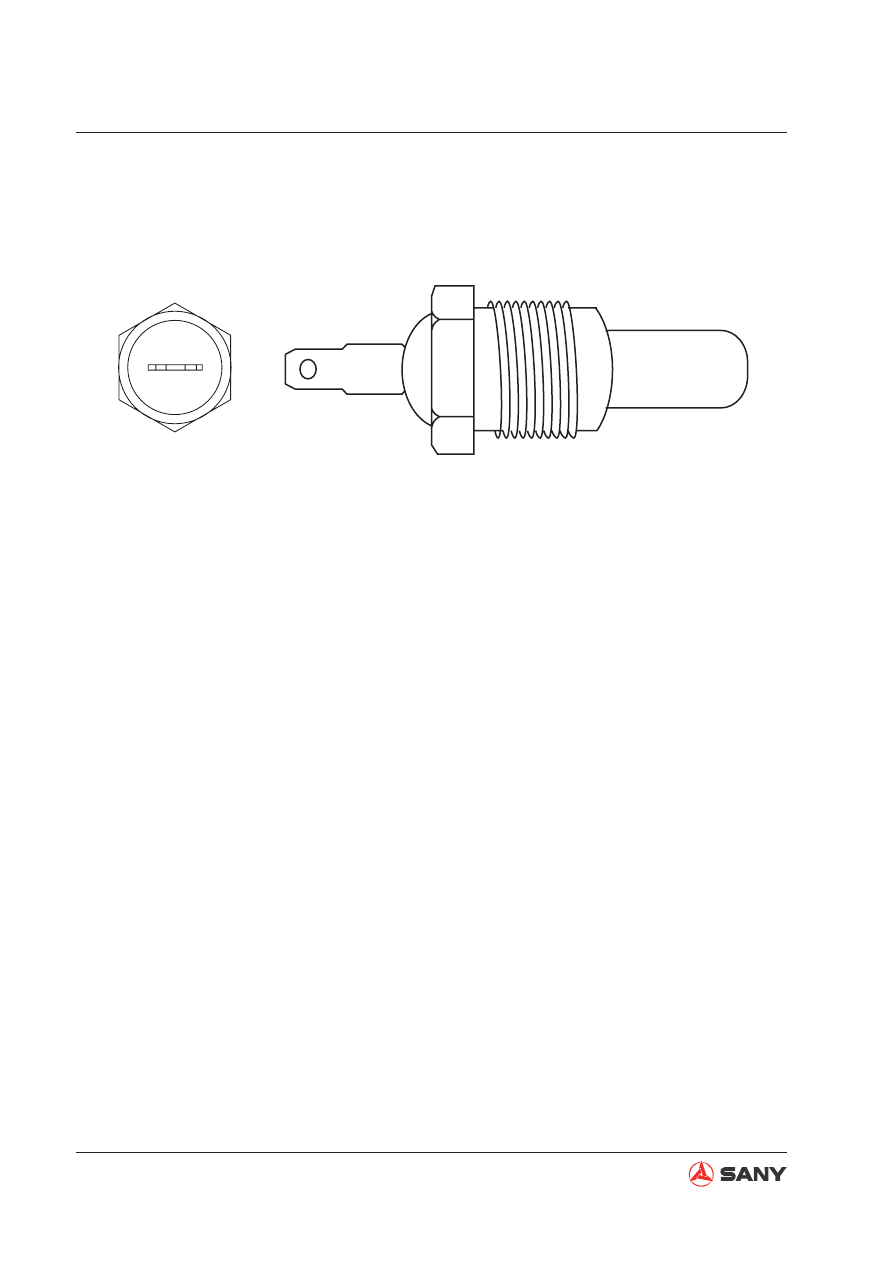
6) Coolant temperature sensor

Fig. 4-204 

Function

The output resistance of engine coolant tem-
perature sensor changes with the tempera-
ture. The controller collects signal and works 
out a cooling temperature.

ZX335-1002071

4-195

Structure and Functions

SY365(B)H-9 Crawler Hydraulic Excavator

4.11 Monitoring System

The machine condition is monitored by the
sensors mounted on different locations of
the machine. The controller processes the
signals and transmits the signals to the
monitor display, informing the operator of
the machine condition.

Information on the monitor display includes
primarily:

1. Alert information in case of machine fail-

ure

2. Operating condition (coolant tempera-

ture, hydraulic oil temperature, fuel level,
etc. )

The monitor panel also contains mode se-
lector, functional keys and machine opera-
tion control outputs.

Fig. 4-205 

ZX335-1002073

CAN signal

Each sensor

Controller

Power

Battery

Monitor

A

B

F1

F2

F3

F4

F5

Esc

Enter

4-196

Structure and Functions

SY365(B)H-9 Crawler Hydraulic Excavator

4.11.1 Monitor

SECD_5I7D

Outline


The monitor is used to display monitoring 
information and select a working mode.


The monitor has a CPU (Central Process-
ing Unit) which processes, displays, and 
outputs information.


The monitor uses a LCD (Liquid Crystal 
Display). 

Port I/O signals

$

%

F1

F2

F3

F4

F5

Esc

Enter

WX215-1204002H

Fig. 4-206 

No.

Signal name

I/O

1

Digital input A

Input

3

CAN high

4

CAN low

8

Trigger power (24V)

9

Power supply (24V)

10

Ground

12

Ground

IMPORTANT


Technical specification allows a screen to 
have not-more-than 10 dark spots (not il-
luminated) or bright spots.


It is normal to have blue bright spots on the 
screen when the monitor is on for a quite 
period of time.


It is normal to have blinking strips on the 
screen when the monitor initializes.

4-197

Structure and Functions

SY365(B)H-9 Crawler Hydraulic Excavator

4.11.2 Monitor panel

A

B

F1

F2

F3

F4

F5

Esc

Enter

XP235-13001

A

B

C

$

%

XP235-13002

Fig. 4-207 

Fig. 4-208 

NOTICE


Stop operation immediately when the 
alert indicator is on. Check and repair 
related parts.


The monitor does not display all work-
ing conditions of the machine.


Do not solely depend on what is dis-
played on the monitor when maintain-
ing and checking the machine. 

The monitor panel performs the functions of 
monitoring and displaying, selecting a working 
mode, and switching on/off an electrical ele-
ment.

Overview

The monitor consists of three parts:

A: Alert indicators

B: LCD display

C: Operation keys

4.11.2.1   Alert and signal indicators

Alert indicator

When the excavator has a problem, the alert 
indicator flashes five times along with five 
buzzing. If the fault is still there, the indicator 
light A will be kept on, telling user to solve the 
problem.

4-198

Structure and Functions

SY365(B)H-9 Crawler Hydraulic Excavator

4.11.2.2 LCD display

When start switch of excavator is turned to 
the ON position, the monitor is energized by 
machine batteries and enters the initializing 
screen. As shown by the 

fi

 gure on the right, a 

fully displayed screen includes the following 
information:

(1) Working mode

(2) Coolant temperature gauge

(3) Fuel level gauge

(4) Failure code

(5) Total service hours

(6) Function icons

(7) Local time

(8) Local date

(9) GPS signal indication

(10) Engine speed level

E101

Sany Hydraulic Excavator

0032

h

25

m

09:32:24

11/11/01

1

S

C

H

F

E

s

n/min

AUTO

XP235-13003

1

2

3

4
5

6

7

8

9

10

Fig. 4-209 

A

B

C

XP235-13004

Fig. 4-210 

Coolant temperature gauge

There are a total of 13 segments (yellow) for 
the full range from zero to 120 degrees.

A: When the engine is just started.

B: When temperature is between zero and 110 

degrees.

C: When temperature is over 110 degrees, 

the last segment turns red and the alert 
indicator is on at the same time. When the 
temperature goes back to a level under 110 
degrees, the alert indicator goes off auto-
matically.

4-199

Structure and Functions

SY365(B)H-9 Crawler Hydraulic Excavator

A

B

C

XP235-13005

Fig. 4-211 

F1

F2

F3

F4

F5

Esc

Enter

A

B

XP235-13006

Fig. 4-212 

Fuel level gauge

There are 13 yellow segments indicating a 
range from 0 to 100%.

A: Fuel level is lower than 8%. There is no 

segment shown. Alert indicator is on at the 
same time.

B: Fuel level is over 8%. Alert indicator goes 

off.

C: Fuel level is 100%.

4.11.2.2 Operation keys

The operation keys include function keys and 
navigation keys.

A: Function keys

B: Navigation keys

4-200

Structure and Functions

SY365(B)H-9 Crawler Hydraulic Excavator

Function keys

There are 

fi

 ve function keys, i.e. F1, F2, F3, F4 and F5. These keys are de

fi

 ned by the icons dis-

played above them.

Function of the same key may vary as the icon above it changes.

A key is disabled when no icon is displayed above it.

Common icons and corresponding keys are given in the following table.

Function keys

Icon dis-

played

Functions

Display range

F1

s

Change working mode.

H

S

L

B

F2

n/min

AUTO

Shift to full speed/auto idling.

Full speed/auto idling

F3

Shift to high/low travel speed.

High/low speed

F4

Enter an option/setup item.

Same as the Enter key

F5

View system information.

——

Back to previous page.

Same as the ESC key

Operation keys

Functions

Enter

Enter an option/setup item.

ESC

Back to previous page.

UP (The highlight goes to the bottom item after the top one.) Increase the 
value of digit at the cursor.
DOWN (The highlight goes to the top item after the bottom one.) Decrease the 
value of digit at the cursor.
LEFT (The highlight goes to the right most item after the left most one.) Move 
the cursor leftward.
RIGHT (The highlight goes to the left most item after the right most one.) 
Move the cursor rightward.

Operation keys

4-201

Structure and Functions

SY365(B)H-9 Crawler Hydraulic Excavator

4.11.3  Monitor display and operation

4.11.3.1 Default page

Default page is shown during normal operation 
of the excavator.

Operation

1. Working mode

Press the key F1 to change working mode 
to H, S, L or B in a cycle manner.

H mode - Heavy-duty operation

S mode - Standard operation

L mode - Light-duty operation

B mode - Breaker operation

NOTE

: S is the default mode after the machine 

is powered on.

2. Selecting auto idling

Press the key F2 to disable/enable auto idling 
function.

When the icon 

n/min

AUTO

 appears above the key F2 , 

press the key to disable auto idling; when the 
icon 

n/min

 appears above the key F2 , press the 

key to enable auto idling.

NOTE

: When the machine is powered on, auto 

idling is enabled as default.


Auto idling is active as default. When all 
control levers are in neutral position for 
more than 0.2 seconds, engine speed will 
drop by 100 rpm immediately and then 
enter auto idling after another 3 seconds 
(controller will reduce engine speed to 
idling) in order to reduce fuel consumption 
and noise.


In idling, if the controller detects any ma-
neuver or gear change, engine speed will 
restore respective level.

3. Selecting high/low travel speed

Press the key F3 to switch between high and 
low travel speeds. When the symbol

ap-

pears above the key F3 , press the key to 
select high speed travel; when the symbol


appears above the key F3 , press the key to 
select low speed travel.

NOTE

: When the machine is powered on, low 

speed is the default travel speed.

4. Viewing failure information

When alert indicator of the monitor is on, a fail-
ure code will appear on bottom line of monitor 
screen. Meanwhile, a red tick appears above 
the key F4 . Press the key to see failure infor-
mation.

5. Viewing system information

Press the key F5 to see system information.

NOTE

: To see system information requires 

password. Please contact your Sany distribu-
tor.

E101

0032

h

25

m

09:32:24

11/11/01

1

C

H

F

E

s

n/min

AUTO

XP235-13007

S

Sany Hydraulic Excavator

Fig. 4-213 

4-202

Structure and Functions

SY365(B)H-9 Crawler Hydraulic Excavator

4.11.3.2  

Password entry to system information

Press F5 on the default page to enter the 
password entry to system information. You 
need to enter the correct password prior to ac-
cess to System Information.

Key operation


Press F1 or

 or

 to increase or de-

crease the number on the digit with the 
cursor.


Press F2 or

 or

 to move the cursor to 

the left or right digit.


Press F3 to enter System Unlock.


Press F4 to enter Backlight Adjustment.


Press F5 or ESC to return to the default 
page.


Press Enter to check the validity of pass-
word. If the password is valid, you have ac-
cess to the Main Menu.

Please enter password:

XP235-13008

System Information

Fig. 4-214 

Fig. 4-215 

4.11.3.3 Main menu

Key in the correct password and press Enter 
on the password entry to access System Infor-
mation.

This page contains a list of system functions. 
You can pick up an item and enter respective 
page.

Key operation


Press F1 or

 or

 to scroll up or down 

the menu. When you scroll down the 
menu, the highlight returns to the top item 
after the bottom one.


Press F2 or Enter to enter highlighted item.


Press F4 to go to System Setup.


Press F5 or ESC to return to the default 
page.

Main Menu

Operating Information

Failure Information

Throttle Help Info

Language Selection

SYS Clock Setup

GPS Information

Running parameters of engine, 
main pump and main valve.

XP1251203007

4-203

Structure and Functions

SY365(B)H-9 Crawler Hydraulic Excavator

4.11.3.4  Engine & throttle signals

Select Running information on the Main Menu 
and press F2 or Enter to see Engine & Throttle 
Signals.

This page contains operating parameters of 
engine and throttle signals.

Key operation

Press F1 to see Pilot Pressure Signals.

Press F5 or ESC to return to the Main
Menu.

Engine & Throttle Signals

Coolant Temp  

℃:

10 

Fuel Level     %

10

Eng Oil Press   kPa

10

Throttle Gear     N

10

Engine Speed rpm

10

Gear Position     V

10

Throttle Position     V

10

XP1251203008

Fig. 4-216 

Fig. 4-217 

4.11.3.5  Pilot pressure signals

Press F1 on the page of Engine & Throttle 
Signals to see Pilot Pressure Signals.

This page shows pilot pressure signals.

Key operation

Press F1 to see Main Pump & Main Valve
Signals.

Press F5 or ESC to return to the Main
Menu.

XP2051203009

Pilot Press Signals

Boom UP kg

10

Boom DOWN kg

10

Arm IN kg

10

Arm OUT kg

10

Bucket DIG kg

10

Bucket DUMP kg

10

Swing  kg

10

Left travel kg

10

Right Travel kg

10

4-204

Structure and Functions

SY365(B)H-9 Crawler Hydraulic Excavator

4.11.3.6  Main pump & main valve signals

Press F1 on the page of Pilot Pressure Sig-
nals to see Main Pump & Main Valve Signals.

This page shows main pump and main valve 
signals.

Key operation


Press F1 to see Engine & Throttle Signals.


Press F5 or ESC to return to the Main 
Menu.

XP2051203010

Main Pump & Main Valve

Pump_1 Main Press Kg

10

Pump_2 Main Press Kg

10

Prop Valve_1 Current mA

10

Prop Valve_2 Current mA

10

Bucket Confl valve

 ○

Swing Priority valve

 ○

Boom Priority valve

 ○

High/Low Speed Shift

 ○

Fig. 4-218 

Fig. 4-219 

4.11.3.7 Failure codes

Select Failure Codes on the Main Menu and 
press F2 or Enter to enter the page.

This page contains failure codes and failure 
information.

Key operation


Press F1 to see next page of failure codes.


Press F5 or ESC to return to the Main 
Menu.

XP2051203011

Failure Information

Current failure code

E101

E101

Controller failure

E102

Controller temp abnormal

E103

Sensor power abnormal

E202

Voltage high

E203

Backup battery volt low

E401

CAN bus abnormal

E501

Fuel control dial abnormal

H101

F. pump press abnormal

H102

R. pump press abnormal

H105

F. pump valve current abnormal

H108

R. pump valve current abnormal

H112

Backup pilot press abnormal

H201

Bucket-dig pilot press abnormal

H202

Bucket-dump pilot press abnormal

H203

Arm-in pilot press abnormal

H204

Arm-out pilot press abnormal

H205

Boom-up pilot press abnormal

4-205

Structure and Functions

SY365(B)H-9 Crawler Hydraulic Excavator

4.11.3.8  Throttle help information

Select Throttle Help Info on the Main Menu 
and press F2 or Enter to enter the page.

This page contains help information for throttle 
installation.

Key operation


Press F2 to select auto idling or full speed.


Press F3 to select high or low speed travel.


When SYFCS controller is used, the icon 
rpm will appear in blue or red color.


Press F5 or ESC to return to the Main 
Menu.

Note

: Only a SYFCS controller allows the 

change of rpm between blue and red colors.

XP2051203013

n/min

AUTO

rpm

s

Throttle Help Info

Current Gear      N

Engine Speed rpm

Gear Position     V

Throttle Position V

XP2051203014

Language Selection

English Systems

中 文 系 统

中文

Eng

4.11.3.9 Language selection

Select Language Selection on the Main Menu 
and press F2 or Enter to enter the page.

This page is used to select a language for the 
system.

Key operation


Press F2 to select Chinese System ( 

中文


系统

).


Press F3 to select English System.


Press F5 or ESC to return to the Main 
Menu.


Press

 or

 to highlight a language up 

or down the list.

Fig. 4-220 

Fig. 4-221 

4-206

Structure and Functions

SY365(B)H-9 Crawler Hydraulic Excavator

4.11.3.10  System clock setup

Select System Clock Calibration on the Main 
Menu and press F2 or Enter to enter the page.

This page is used to set up system clock.

Key operation

Press

 or

 to increase or decrease the

number on the digit with the cursor.

Press

 or

 to move the cursor to the 

left or right digit.

Press F1 or Enter to 

fi

 nish calibration. You

will be prompted by 

Calibration 

fi

 nished!

Please restart your machine.

Press F5 or ESC to return to the default
page.

NOTE

: System clock can only be set up once 

after the machine is powered on. When the 
machine is powered on, the prompt of suc-
cessful calibration remains on the screen if 
you press F1 or the Enter key.

SYS Clock Setup

Use [

][

][

][

] to set p system clock.

XP2051203015

Local time and time zone

1234·12·12   12:12

12 12W

Time and time zone setup

1234·12·12   12:1212 12W

Fig. 4-222 

4-207

Structure and Functions

SY365(B)H-9 Crawler Hydraulic Excavator

4.11.3.11 GPS information

Select GPS Information on the Main Menu and 
press F2 or Enter to enter the page.

This page shows GPS monitoring information.

Key operation

Press F5 or ESC to return to the default page.

Note:

1. The letter 

E

 stands for East Longitude 

and 

W

 for West Longitude.

2. The letter 

N

 stands for North Latitude 

and 

S

 for South Latitude.

3. The letter 

P

 stands for a height above 

the seal level and 

N

 for a height below 

the seal level.

4. The signal-to-noise ratio ranges from 0 to 

99, which is indicated by a bar. The value 
on the right of the bar is real S/N ratio.

5. If the elevation value is not zero and no 

value is displayed for the longitude and lati-
tude, GPS data are being received but the 
location has not been precisely de

fi

 ned yet.

6. When the communication signal is 1023, 

GPRS communication is regular. When it 
is 615, the GPRS communication is abnor-
mal.

7. When the communication signal changes 

from 7 to 0, the SIM card or the antenna 
has a bad connection.

8. When the communication signal changes 

from 15 to 0, GPRS service is not available, 
the SIM card has insuf

fi

 cient fund, or GPRS 

network is abnormal.

9. When the communication signal changes 

from 31 to 0, the monitoring center is 
closed.

10. This page is required for remote system 

locking, remote system unlocking and re-
mote downloading.

XP20512003026

GPS Information

Longitude  °

121.0W

Latitude  °

31.40N

Altitude  m

28.79P

Velocity  Km/h

4.037

Number of Satellites  

0006

Communication Indicator  

1023

Signal to noise ratio 1

Signal to noise ratio 2

Signal to noise ratio 3

Signal to noise ratio 4

d B

d B

d B

d B

Fig. 4-223 

4-208

Structure and Functions

SY365(B)H-9 Crawler Hydraulic Excavator

4.11.3.12 System setup

Press the key F4 on the Main Menu to enter 
System Setup.

This page is used to con

fi

 gure your machine.

Note

: Access to System Setup requires en-

tering the password. For method of entering 
password see 

Password entry to system 

information

 on page 4-202

.

Key operation

Press F1 or or to scroll up or down the
menu. When you scroll down the menu,
the highlight returns to the top item after
the bottom one.

Press F2 or Enter to enter highlighted item.

Press F5 or ESC to return to the Main
Menu.

4.11.3.13 Machine con

fi

 guration

Select Machine Configuration on the Main 
Menu and press F2 or Enter to enter the page.

This page shows machine con

fi

 guration  infor-

mation.

Note

: Access to System Setup requires en-

tering the password. For method of entering 
password see 

Password entry to system 

information

 on page 4-202

.

Key operation

Press F5 or ESC to return to System Set-
up.

Note

V217

 following machine model is 

software version.

XP2051203016

System Setup

Machine Configuration

Service Hour Setup

Machine Configuration Setup

Hydraulic Oil Temperature

Fig. 4-224 

Fig. 4-225 

XP2051203018

Machine Configuration

Machine Model

 SY215C \V217

Machine S/N

 11SY0216 00008

Engine Model

 CUMMINS_II

HYD SYS Model

 KPM_P

Control SYS

 KC-MB-001

4-209

Structure and Functions

SY365(B)H-9 Crawler Hydraulic Excavator

4.11.3.14  Service hour  setup

Select Service Hour Setup on the page of Sys-
tem Setup and press F2 or Enter to enter the 
page.

This page is used to set up service hours of 
the machine.

Note

: Access to System Setup requires en-

tering the password. For method of entering 
password see 

Password entry to system 

information

 on page 4-202

.

Key operation


Press F1 or Enter to save the change af-
ter calibration. You will see on the screen 

Calibration 

fi

 nished! Please restart your 

machine.


Press F5 or ESC to return to System Set-
up.

XP2051203021

Service Hour Setup

Current Service Hours
  100 h  50 m

Service Hour Setup

  100 h  50 m

Use [

][

][

] and [

] to set up service hours.

Fig. 4-226 


Content      ..     16      17      18      19     ..