SANY Crawler Hydraulic Excavator SY365H-9, SY365BH-9. Shop Manual (2014) - page 16
 

  Index      Manuals     SANY Crawler Hydraulic Excavator SY365H-9, SY365BH-9. Shop Manual (2014)


Search            copyright infringement  


Content      ..     14      15      16      17     ..


SANY Crawler Hydraulic Excavator SY365H-9, SY365BH-9. Shop Manual (2014) - page 16


4-162

Structure and Functions

SY365(B)H-9 Crawler Hydraulic Excavator

ZX215-1002175

0

0

01

02

03

04

05

05

0

0

35

MPa

MPa

{cmHg   kgf/cm

2

}

{cmHg   kgf/cm

2

}

5

3

30

25

25

20

10

1

15

2

15

35

- 01

-01

-76

-76

-50

06

07

08

085

8.5

8

7

5

6

4

3

2

1

15


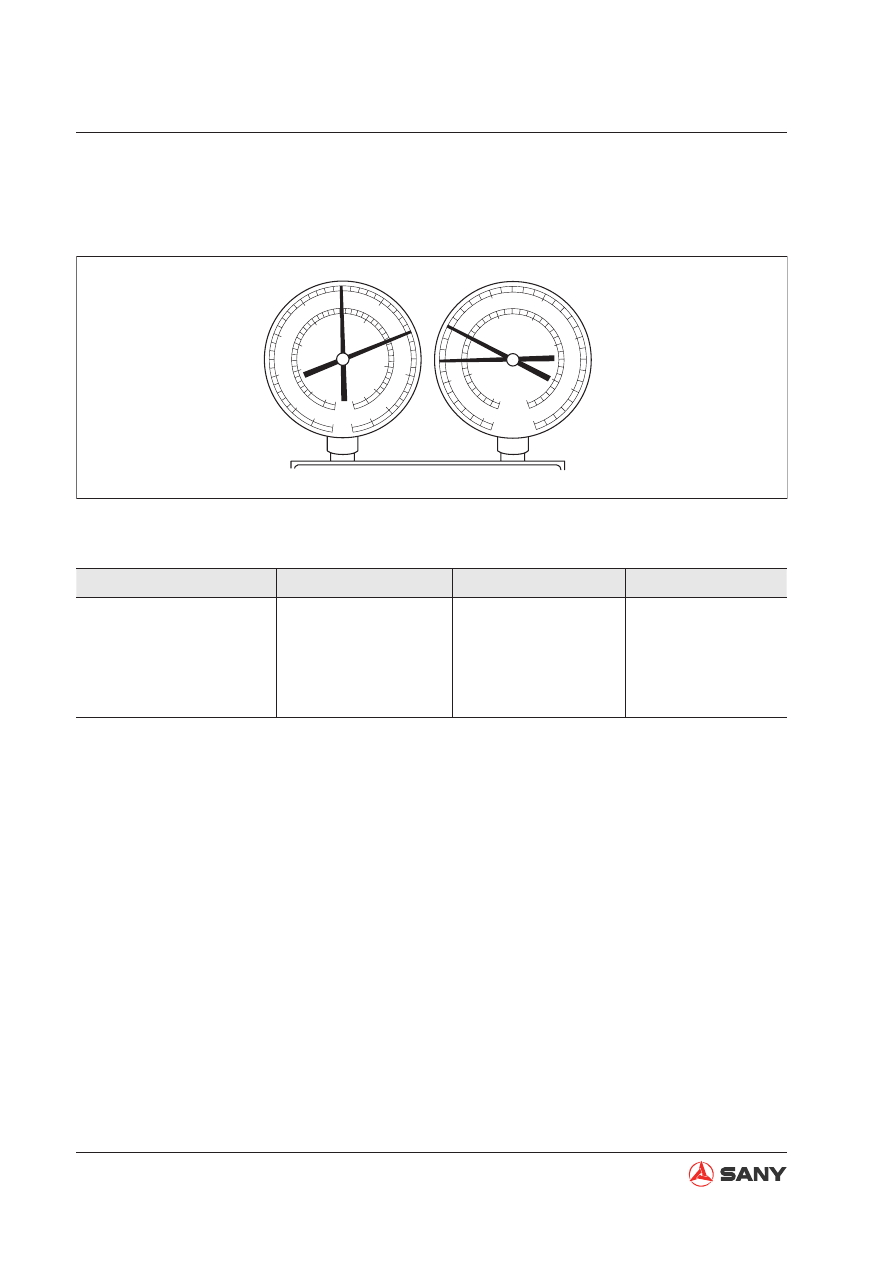
Compressing error

Fault: No refrigeration

Symptom

Cause

Analysis

Remedy


Pressure at Lo-pressure 
side very high


Pressure at Hi-pressure 
side very low


Compressor internal 
leakage


Compressing fault; 


Leaking or damaged 
valve, or missing 
parts


Repair or replace 
compressor

Fig. 4-163 

4-163

Structure and Functions

SY365(B)H-9 Crawler Hydraulic Excavator

4.8.2.1 Compressor oil

Oil shall be added into the A/C system for lubrication. Compressor oil is solved in the refrigerant 
and circulates in the system. When the air conditioning system is shut down, compressor oil will 
stay inside the components. If no compressor oil is added into the system when replacing com-
ponents, inadequate lubrication will result. Add compressor oil according to the chart below:

Replaced component

Compressor

Condenser

Evaporator

Volume (CC)

See "NOTICE" below

40

40

Compressor oil grade

ND8# (10P, 10PA, 10S series compressor)

ND9# (TV series compressor)

NOTICE

Add oil into a new compressor according to the required volume of the system. When

the compressor is to be replaced, discharge the surplus oil in it. 

Filling of improper amount of compressor oil: Over-

fi

 lling of compressor oil will reduce

the refrigerating capacity. Short of compressor oil in the system will lead to an abnor-
mal compressor.

Keep the pipe connectors and O-ring seals free from contamination when disassem-
bling the compressor.

4-164

Structure and Functions

SY365(B)H-9 Crawler Hydraulic Excavator

4.9 Engine Control

(1) Battery relay
(2) Battery
(3) Start switch
(4)  Fuel control dial
(5) Start motor
(6) Controller 
(7)  Fuel injection pump
(8) Throttle motor
(9) Shutdown device

Outline

The engine is only started and stopped
with the start witch (3).

The engine controller (6) receives the sig-
nal from the fuel control dial (4) and trans-
mits the drive signal to the throttle motor (8)
to control the governor lever angle of fuel
injection pump (7) in order to regulate en-
gine speed.

When the start switch (3) is turned to the
OFF position, the shutdown device (9)
closes the injection nozzle of the fuel injec-
tion pump to cut off the engine fuel supply.
Then, the engine stops.

W365-1304503

4

3

5

9

1

2

Z

8

7

6

Z

Fig. 4-164 

4-165

Structure and Functions

SY365(B)H-9 Crawler Hydraulic Excavator

ZX335-1002044

B E

E

E

B

R

s

L

B

Hi

Hi

Lo

Lo

s

M

P

BR

C

C

Fuel control dial

Engine

(Power supply)

Start switch

(Start switch ON siganl)

(Regulating signal)

Monitor - controller

Shutdown
device

Shutdown 
relay

Battery relay

Safety relay

Start motor

(Start signal)

Governor 
motor

Alternator

Throttle ON

Throttle OFF

Pilot switch

Start 
relay

Shutdown 
delay relay

(Start signal)

(Potentiometer signal)

(Driving signal)

ZX335-1002045

B E

E

E

B

R

s

L

B

Hi

Hi

Lo

Lo

s

M

P

BR

C

C

Fuel control dial

Engine

(Power supply)

Start switch

Safety relay

Start motor

(Start switch ON siganl)

(Regulating signal)

Monitor - controller

Shutdown
device

Battery relay

(Start signal)

Governor 
motor

Alternator

Throttle ON

Throttle OFF

Pilot switch

Start 
relay

Shutdown 
delay relay

(Start signal)

(Potentiometer signal)

(Driving signal)

Shutdown 
relay

ZX335-1002046

B E

E

E

B

R

s

L

B

Hi

Lo

s

BR

C

C

Engine

(Power supply)

Start switch

Safety relay

Start motor

(Start switch ON siganl)

Monitor - controller

Shutdown
device

Battery relay

(Start signal)

Governor 
motor

Alternator

Throttle ON

Throttle OFF

Pilot switch

Start 
relay

Shutdown 
delay relay

(Start signal)

Shutdown 
relay

4.9.1 System operation

4.9.1.2  Engine speed control

The fuel control dial sends to the controller
a signal voltage corresponding to its angle.

According to the signal voltage, the control-
ler sends a driving signal to throttle motor
in order to control the fuel injection pump,
hence controlling the engine speed.

4.9.1.3 Engine shutdown

When the start switch is turned to the
STOP position, the shutdown controller
controls the shutdown device to stop fuel
supply to the fuel feed pump. The engine
is then stopped.

4.9.1.1 Engine starting

When the start switch is turned to the
START position, the starting signal is sent
to the start motor. Then, the start motor
starts the engine.

When it happens, the engine controller de-
tects the signal voltage sent from the fuel
control dial and sets the engine speed to
the speed set by the fuel control dial.

Fig. 4-165 

Fig. 4-166 

Fig. 4-167 

4-166

Structure and Functions

SY365(B)H-9 Crawler Hydraulic Excavator

4.9.2 System components

4.9.2.1  Fuel control dial

ZX215-1002180

25°

140°

9×10°

1

2

3

4

5

5V

0V

VR

1

2

3

6

1

2

3

Yellow

Blue

Red

Leftmost position

Rightmost position

Gear position 1

Gear position 10

(1) Knob
(2) Dial
(3) Spring
(4) Ball
(5) Potentiometer
(6) Plug

Fig. 4-168 

4-167

Structure and Functions

SY365(B)H-9 Crawler Hydraulic Excavator

ZX215-1002181

%

V

100

0

0.25 1.72

4.49 4.75 5

Dial angle

Voltage (V)

Function

Turning of the fuel control dial changes the
resistance of the sliding rheostat inside
the dial and the voltage signal collected by
the controller. The controller calculates the
collected signals and drives the governor
motor via signal output and controls the in-
jection of the fuel pump so that the engine
can run at an optimal speed.

When throttle voltage is beyond the area,
the controller sends out alarm code and
the engine runs at low idle. The area under
the sloping line is the abnormality detection
area.

Remark: 

The leftmost position is 0%; and the rightmost 
position is 100%. 

Fig. 4-169 

4-168

Structure and Functions

SY365(B)H-9 Crawler Hydraulic Excavator

4.9.2.2 Controller

SEHC-281A (Huaxing)

Controller ports

J1-2 40 pins

J1-1 81 pins

WT365-1304001

Fig. 4-170 

W365K-1304002

........

........

........

........

...................

...................

...................

...................

J1-1

J1-2

Fig. 4-171 

4-169

Structure and Functions

SY365(B)H-9 Crawler Hydraulic Excavator

Controller signal distribution

J1-2

No.

Signal name

I/O

82

High/low speed shift valve

88

Front pump proportional valve

89

Rear pump proportional valve

98

Bucket con

fl

 uence valve

99

Engine start control

100 Shutdown delay signal
101 Bucket solenoid valve
105 Throttle motor drive signal+

113 Throttle motor drive signal-
114 Power ground
115 Power ground
116 Power ground
117 Power ground
118 Power

24V

119 Power

24V

120 Power

24V

121 Power

24V

J1-1

No.

Signal name

I/O

1

Power ground

2

Power ground

3

Power ground

4

Power

24V

Input

5

Power

24V

Input

11

Fuel level sensor signal

Input

13

GPS detecting signal

15

Throttle position signal

Input

23

RX232

28

Air 

fi

 lter plugging sensor signal

Input

30

Water temp sensor signal

Input

31

Oil temp sensor signal

Input

34

Fuel control dial signal

Input

38

Engine speed signal

39

2RS

40

RS

41

TX232

42

2nd boost button signal

48

Engine oil pressure signal

Input

49

L. travel pressure sensor

Input

50

Bucket-dig pressure sensor

Input

51

Boom-down pressure sensor

Input

52

Arm-in pressure sensor

Input

53

Rear pump principal pressure
sensor

Input

54

Sensor power ground

Input

55

Sensor power ground

Input

56

Sensor power

Output

58

Monitor CAN low

60

Calibrator CAN high

65

Pilot switch

66

Coolant temp high

Input

67

R. travel pressure sensor

Input

68

Swing pressure sensor

Input

69

Bucket-dump pressure sensor

Input

70

Boom-up pressure sensor

Input

71

Arm-out pressure sensor

Input

72

Front pump principal pressure
sensor

Input

73

Sensor power ground

Input

74

Sensor power

Output

75

Sensor power

Output

77

Monitor CAN low

78

Calibrator CAN high

79

Engine shutdown signal

80

Engine start signal

4-170

Structure and Functions

SY365(B)H-9 Crawler Hydraulic Excavator

4.10  Electrical Control System

4.10.1 Control function

Engine - pump combination control

Pump control 

Valve control

Dual-speed Travel control

Electrical control system

Auto deceleration/acceleration control

Low Engine oil pressure alarm

Engine preheat/overheat alarm

Engine speed calibration

Self-diagnostic function

4-171

Structure and Functions

SY365(B)H-9 Crawler Hydraulic Excavator

4.10.2  Diagram of machine control system

2

3

5

6

7

8

9

10

12

13

14

15

16

4

11

1

W365413081

Battery

Battery relay drive

Fuse

Start switch

Shutdown
delay relay

Fuel level sensor

Fuel level signal

Signal monitoring info

CAN bus

Monitor controller
integration

Start relay

PPC lock signal

Safety relay

Charge indicator

Start signal

Preheat signal

Preheater relay

Controller
HCU

Working mode signal
Travel speed select signal
Auto deceleration signal
Signal monitoring info

Engine speed sensor  Motor      Potentiometer

Engine oil pressure
Coolant temp signal
Battery charge signal

Eng oil press sensor
Eng coolant temp sensor
Alternator 
Air filter plugging switch
Start motor
Electric air heater

Engine

R pump outlet press signal
F pump outlet press signal

F pump control signal

R pump control signal

Power regulator valve signal

Travel speed select signal

Right travel signal

Left travel signal

Boom-up signal

Boom-down siganl

Arm-in signal

Arm-out signal

Bucket-dig signal

Bucket-dump signal

Swing signal

Fuel control dial

Power supply

Power supply

Energizing signal

Starting signal

Starting signal

Engine speed

Motor drive signal

Real throttle position 

feedback signal

Preheating signal

Fig. 4-172 

4-172

Structure and Functions

SY365(B)H-9 Crawler Hydraulic Excavator

Note:  

The diagram above is a schematic diagram of electrical control. See the hydraulic section 

for more information on the hydraulic circuits.

W365413082

1

2

3

4

5

6

7

8

9

10

11

15

12

13

16


F

R

PPC

14

R. travel pressure sensor

L. travel pressure sensor

Boom-up pressure sensor

Boom-down pressure sensor

Arm-in pressure sensor

Arm-out pressure sensor

Bucket-dig pressure sensor

Bucket-dump pressure sensor

Swing pressure sensor

PPC
valve

Main pump

Servo

Servo

Power limit
solenoid valve

Rear pump oil feed device

Work equipment rotating device

Work equipment rotating device

Swing motor

Swing motor

Swing motor

Main valve

PPC basic pressure

lock valve

Rear pump
proportional
valve

Front pump
proportional
valve

Two-speed
solenoid 
valve

Frong pump oil feed device

Port for each action control valve

Fig. 4-173 

4-173

Structure and Functions

SY365(B)H-9 Crawler Hydraulic Excavator

4.10.3  Engine-pump combination control

W365413083

MIN

MAX

P2

P1

A

B

F1

F2

F3

F4

F5

Esc

Enter

Pilot valve

Travel

Travel

Cab

Arm in/out
Swing

Boom up/down
Bucket dig/dump

Fuel control dial

Pressure 
sensor

MC controller input
H/S/L/B
Cancel auto deceleration
Shift travel speed
Alarm output

Controller

Main control valve

Pressure
sensor

Pump

Pump proportional
pressure reducing
solenoid valve

Throttle motor

Engine chamber

Motor

Potentiometer

Fuel, coolant temp & others

Control rear pump inclination

Control front pump inclination

Engine speed

Actual throttle position feedback

Control motor

Pilot oil pressure

Engine feed 
regulation

Fig. 4-174 

4-174

Structure and Functions

SY365(B)H-9 Crawler Hydraulic Excavator

Function


This function allows operator to select a 
working mode and change the engine pow-
er output according to the kind of job that 
the machine is to be engaged. The working 
modes include H, S, L and B. A selector 
button on the monitor is available for selec-
tion of a working mode. 


Pump controller controls the pump so that 
the pump is able to absorb all torques at 
engine output point. These torques are 
determined by the pump absorption torque 
specification, fuel control dial setting and 
real engine speed under each mode. 

6

7

1

10

9

ZX335-1002051

Engine power KW

Engine speed N

H

S

L

ZX335-1002052

S

Pump flow Q

Pump output pressure P

H

L, B

Fig. 4-175 

Fig. 4-176 

Fig. 4-177 

Technical speci

fi

 cations

H mode

Speed (rpm)

~1750

1750~1900 1900~2180

Power(KW)

143

159

174

S mode

Speed (rpm)

~1750

1750~2180

Power(KW)

133

166

L mode

Speed (rpm)

~1850

Power(KW)

150

4-175

Structure and Functions

SY365(B)H-9 Crawler Hydraulic Excavator

Mode control methods

Mode H

H mode matching point: Rated speed

1

84kW/2180rpm

Engine speed decreases when pump load
increases and the pressure rises. In this
case, engine speed will be up to the prox-
imity of matching point, allowing pump con-
troller to reduce output. On the contrary,
when pump load reduces and the pressure
decreases, the pump controller will keep
increasing pump output until engine speed
reaches the proximity of matching point.

ZX335-1002053

Engine torque T

Engine speed N

ZX335-1002054

Engine power KW

Engine speed N

ZX335-1002055

Pump output pressure P

Pump flow Q

Fig. 4-178 

Fig. 4-179 

Fig. 4-180 

4-176

Structure and Functions

SY365(B)H-9 Crawler Hydraulic Excavator


The controller maintains the pump suction 
force along the stable horse power curve 
and controls engine speed through engine-
pump combination control. 


Power output percentage corresponding to 
each mode

Mode

H

S

L

B

Power out-

put percent-

age

95%

90%

80%

80%

6

7

1

10

9

ZX335-1002051

Engine power KW

Engine speed N

H

S

L

ZX335-1002052

S

Pump flow Q

Pump output pressure P

H

L, B

Fig. 4-181 

Fig. 4-182 

Fig. 4-183 

4-177

Structure and Functions

SY365(B)H-9 Crawler Hydraulic Excavator

4.10.4  Pump control function

W365413084

M

P


R

F

Hi

Lo

Engine

Controller

Pressure sensor

Pressure sensor

Main pump

Injection
pump

Governor
motor

Speed
sensor

Servo

Servo

Fuel control dial

Valve

Valve

Swing signal

Bucket DUMP signal

Bucket DIG signal

Arm OUT signal

Arm IN signal

Boom DOWN signal

Boom UP signal

Left travel signal

Right travel signal

(Control signal)

(Control signal)

(Engine speed signal)

Fig. 4-184 


Content      ..     14      15      16      17     ..