SANY Crawler Hydraulic Excavator SY365H-9, SY365BH-9. Shop Manual (2014) - page 14
 

  Index      Manuals     SANY Crawler Hydraulic Excavator SY365H-9, SY365BH-9. Shop Manual (2014)


Search            copyright infringement  


Content      ..     12      13      14      15     ..


SANY Crawler Hydraulic Excavator SY365H-9, SY365BH-9. Shop Manual (2014) - page 14


4-130

Structure and Functions

SY365(B)H-9 Crawler Hydraulic Excavator

4.8  Operator Station and Its Attachments

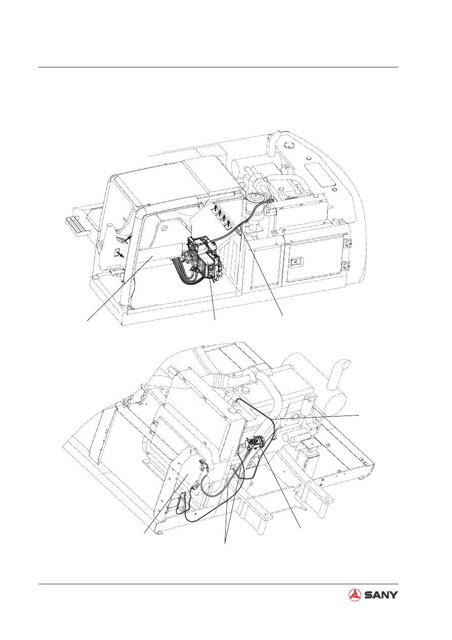
4.8.1  Air conditioner lines

ZX335-1002042

A

B

C

C

C

C

2

3

4

5

7

1

6

Fig. 4-126 

4-131

Structure and Functions

SY365(B)H-9 Crawler Hydraulic Excavator

(1) Air conditioner

(2)  Hot water pumping line

(3) Air compressor

(4) Refrigerant line

(5) Condenser

(6)  Hot water return line

(7) Duct

A:  Fresh air

B:  Recirculated air

C:  Warm air / cool air

4-132

Structure and Functions

SY365(B)H-9 Crawler Hydraulic Excavator

4.8.1.1  Layout of A/C components

ZX215-1002138

1

2

3

4

5

6

7

(1) Sunlight sensor
(2) Control panel
(3)  Air conditioning unit
(4) Condenser
(5) Compressor
(6)  Fresh air sensor
(7)  Recirculated air sensor

Fig. 4-127 

4-133

Structure and Functions

SY365(B)H-9 Crawler Hydraulic Excavator

4.8.1.2  A/C control panel

Remark:

When auto mode switch (5), fresh air/recircu-
lation control (6) and A/C power (8) are turned 
on, indicator lights above these switches will 
light up.

(1) OFF switch
(2)  Fan speed control switch
(3)  Temperature control switch
(4)  Air outlet mode switch
(5)  Auto mode switch
(6)  Fresh air/recirculation control
(7) LCD display
(8) A/C power

W365413093

6

1

2

3

4

5

7

8

FULL AUTO AIRCONDITION

OFF

TEMP

MODE

AUTO

A/C

Fig. 4-128 

4-134

Structure and Functions

SY365(B)H-9 Crawler Hydraulic Excavator

4.8.1.3  Diagram of electrical circuit

ZX215-1002140

M

M

CM

1.256

1.25L

M

M

M

25

30

29

28

27

23

15

15

33

15

15

15

15

12

14

13

13

13

15

15

10

8

8

8

8

13

7

9

9

1

1

1

2

2

2

7

4

4

4

3

3

3

02

02

02

02

03

03

02

02

01

06

06

7

5

5

5

6

10

10

10

10

12

12

11

16

16

16

19

19

17

18

21

22

25

22

24

26

25

22

20

31

30

31

32

22

22

32

32

34

34

35

35

35

24

26

M

M

RF

GND

Pt

Vz

REC

FFE

28

G

8

6

BLCM

SP

HL

0.5B

AC

M

M

AM

S

SD

TH

F

TH

I

TH

W

TH

AM

M

V1

M

V2

2G

2RL

M

R

D

D

1

ACC

200W

0.50

2B

2B

80W

1.25B

1.25B

0.85B

2B

40W

BLC

RL

CH

43

2

1

EC

C

RL

CH

R

CD

BA

T

40A

FL

Z

CM

B

60A

15A

20A

1.25R

+B

RL

SF

G

CM

B

RL

CH

RL

CD

RL

CC

SP

CD

M

CD

RL

BM

FU

CD

FU

RM

FL

1

D

2

SW

1.25RL

15

19

16

14

12

13

16

27
4

21
20

22

23

1

22

4

25
9

38

26

10

3

RL

BM

RL

CD

RL

CC

FU

M

1.25R

H

OFF

B

G

1

G

2

ACC
MS
T

ACC

ON

START

SW 

5A

Fig. 4-129 

4-135

Structure and Functions

SY365(B)H-9 Crawler Hydraulic Excavator

Wire No.

Diameter/Color 

Code

Wire Color

Wire No.

Diameter/Color 

Code

Wire Color

B

Black

0.5VW

Violet+white

Br(R)

Brown

0.5YB

Yellow+black

0.85W

White

0.5WO

White+orange

RL

Red+blue

0.5PB

Pink+black

G

Green

0.5VR

Violet+red

0.5BL

Black+blue

0.5BG

Black+green

0.5R

Red+blue

0.5WY

White+yellow

0.5Y

Yellow

0.5WR

White+red

0.5BR

Black+red

0.5BrW

Brown+white

0.5BrY

Brown+yellow

0.5GO

Green+orange

0.5BY

Black+yellow

0.5Sb

Sky blue

0.5GW

Green+white

0.5OW

Orange+white

0.5LO

Blue+orange

1.25V

Violet

0.5PG

Pink+green

1.25RG

Red+green

0.5RY

Red+yellow

1.25RW

Red+orange

0.5BW

Black+white

0.85GL

Green+Blue

0.5LgR

Light green+red

Code

Name

Code

Name

Code

Name

AC

M

A/C ampli

fi

 er

FU

CD

Condenser fuse

RL

CH

Condenser high speed 
relay

BAT

Battery

FU

M

A/C main fuse

RL

SF

Protective relay

BLC

Speed regulating resistor

G

Alternator

S

SD

Sunlight sensor

CM

B

Battery relay

M

AM

A/M servo motor

SP

CD

Condenser pressure 
switch

D

Diode

M

B

Blower motor

SP

HL

Hi\Lo pressure switch

D

1

Diode 1

M

CD

Condenser motor

SW

Switcher

D

2

Diode 2

M

RF

Fresh/recirculated air 
servo motor

TH

AM

Recirculated air therm-
istor

EC

C

Compressor clutch

M

V1

Air outlet servo motor

TH

F

Anti-frosting thermistor

FL

1

Fuse

M

V2

FRONT outlet servo motor

TH

I

Recirculated air therm-
istor

FL

2

Fuse

R

CD

Condenser resistor

TH

W

Water temp thermistor

FU

BM

Blower fuse

RL

BM

Blower main relay

RL

CC

Compressor relay

RL

CD

Condenser relay

4-136

Structure and Functions

SY365(B)H-9 Crawler Hydraulic Excavator

4.8.1.4 Operating principle

Refrigeration cycle diagram

ZX215-1002141

Cool air

Lo-pressure part

Warm air

Hi-pressure part

Lo temp\Lo press\Gas

Air in cab

Hi-temp hi-pres gas

Out side fresh air

Cooling fan

Lo temp\Lo press\Liquid (Mist)

Hi temp\Hi press\Liquid

Lo-pres.
side

Hi-pres.
side

Compressor

Blower motor

Evaporator

Reservoir

Expansion valve

Heating cycle diagram

ZX215-1002142

Engine

Water pump

Water tank radiator

Water valve switch

Warm air

Blower motor

Air in cab

Low temp water
High temp water

Fig. 4-130 

Fig. 4-131 

4-137

Structure and Functions

SY365(B)H-9 Crawler Hydraulic Excavator

4.8.1.5 Compressor

ZX215-1002143

1

2

3

4

5

6

7

8

9

10

11

12

13

14

15

16

(1) Stator
(2)  Front radial bearing
(3) Thrust bearing
(4)  Front radial bearing
(5)  Rear cylinder head
(6) Safety valve
(7)  Rear cylinder block
(8) Swash plate
(9) Slipper
(10)  Front cylinder block
(11) Piston
(12)  Front cylinder head
(13) Shaft seal
(14) Main shaft
(15) Boss
(16) Rotor

Operating principle

Compressor type: 10S15C. This compres-
sor has 5 plungers in total with a piston at 
both sides of each plunger. The rotation of 
the swash plate drives the pistons to move 
back and forth and transforms the refrigerant 
sucked from the evaporator from low tempera-
ture and low pressure gas state to high tem-
perature and high pressure state.

Fig. 4-132 

4-138

Structure and Functions

SY365(B)H-9 Crawler Hydraulic Excavator

ZX215-1002144

Process

1

Process

6

Process

5

Process

4

Process

3

Process

2

HI press.end pipe LO press.end pipe

Valve plate

Outlet valve disc

Main shaft and swash plate

HI press.end pipe

HI press.end pipe

HI press.end pipe

HI press.end pipe

HI press.end pipe

LO press.end pipe

LO press.end pipe

LO press.end pipe

LO press.end pipe

LO press.end pipe

Intlet valve disc

Fig. 4-133 

4-139

Structure and Functions

SY365(B)H-9 Crawler Hydraulic Excavator

ZX215-1002145

1

2

3
4

5

6

4.8.1.6 Clutch

(1) Rotor
(2) Stator coil
(3) Clasp
(4) Ball bearing
(5) Stator
(6) Center piece

The electromagnetic clutch is used to
transmit moment of torsion. When the en-
gine is operating, the compressor  may not
be working. The clutch controls the opera-
tion of the compressor only when the air
conditioner is under refrigerating mode.

Operating principle

When the A/C power is turned on, the
clutch coil with an electromagnet gener-
ates a magnetic 

fi

 eld and attracts the metal

piece. The stator and rotor of the clutch are
engaged and bring the main shaft of the
compressor into rotation.

Fig. 4-134 

4-140

Structure and Functions

SY365(B)H-9 Crawler Hydraulic Excavator

4.8.1.7 Condenser

ZX215-1002146

1

2

3

5

4

(1) Condenser core
(2) Bracket
(3)  Bolt with washer
(4) Refrigerant inlet
(5) Refrigerant outlet

Function

The condenser changes high-temperature,
high-pressure gas refrigerant (16Kg/cm²,
approx. 80

) to high-temperature and

high-pressure liquid refrigerant (16Kg/cm²,
below approx. 60

) through radiating.

Fig. 4-135 

4-141

Structure and Functions

SY365(B)H-9 Crawler Hydraulic Excavator

4.8.1.8 Expansion valve

4.8.1.9 Evaporator

ZX215-1002147

1

2

3

4

Evaporator

Reservoir

Compressor

ZX215-1002148

1

2

Operating principle

Refrigerant from the reservoir spurts out via 
the orifice, turns into low-temperature, low-
pressure liquid (mist) after immediate expan-
sion, and enters the evaporator. 

(1) Spring
(2) Diaphragm
(3) Probe
(4) Needle valve

Operating principle

The evaporator is a kind of heat exchanger 
that looks like a condenser. Warm air in the 
cab is conducted into the evaporator via the 
blower motor and undergoes heat exchange 
with the surface of the evaporator. Heat is ab-
sorbed and warm air turns into cool air, which 

fl

 ows into the cab through the air ducts.  Evap-

orator surface absorbs heat

Refrigerant in 

the evaporator absorbs heat 

 Refrigerant 

evaporates . Evaporated refrigerant (gas) is 
absorbed by the compressor.

(1) Expansion valve
(2) Evaporator

Fig. 4-136 

Fig. 4-137 

4-142

Structure and Functions

SY365(B)H-9 Crawler Hydraulic Excavator

4.8.1.10 Dehydrator 

ZX215-1002149

1

2

3

4

Function

Temporary storage of refrigerant

Dehydration of refrigerant

Removing dust from refrigerant

Measuring the volume of refrigerant

(1) Inlet
(2) Outlet
(3) Receiver/dehydrator
(4) Desiccant

Fig. 4-138 

4-143

Structure and Functions

SY365(B)H-9 Crawler Hydraulic Excavator

4.8.1.11 Pressure switch 

Operating features: 

Feature

DIFF

Above 0.02 MPa

OFF

ON

DIFF

0.59±0.2 MPa

0.196±0.02 MPa

0.196~0.250 MPa

2.94~3.19 MPa

ON

OFF

1.23±0.1 MPa

1.52±0.08 MPa

High pressure

Low pressure

Medium pressure

ZX215-1002150

1

2

3

4

5

6

7

Pressure

Function

The pressure switch is installed between
the reservoir and the expansion valve (hi-
pressure pipe). It is a combination switch
(Hi-Lo pressure combination switch).

When pressure is excessively high, the
compressor stops.

When pressure is excessively low, the low-
temperature condition disappears.

(1) O-ring
(2)  Mobile contact point
(3) Hood
(4) Plug and 

fi

 xed contact

(5) Spring
(6) Chamber
(7) Diaphragm

Fig. 4-139 

4-144

Structure and Functions

SY365(B)H-9 Crawler Hydraulic Excavator

4.8.1.12  Fresh air sensor

Fresh air temperature sensor is mounted be-
side the condenser or at the fresh air inlet. 
Consisting of thermistors, it is used to detect 
ambient temperature. 

Speci

fi

 cation

Item

Speci

fi

 cation

Applicable voltage

4.4~5.6 V

Applicable temperature

-30~60 

Storage temperature

-40~90 

Resistance

1700

±

85

Ω

B Constant

3900

±

195 K

Permissible working cur-
rent

1.6 mA (MAX)

ZX215-1002151

12

10

2

12

8

6

4

2

Resistance /K

ȍ

-10

AT

0

10

20

30

40

Fig. 4-140 

4-145

Structure and Functions

SY365(B)H-9 Crawler Hydraulic Excavator

4.8.2 Refrigerant

Compressor

Intake

ė

Discharge

Evaporator

Absorb heat

ė

Emit cold air

Condensor

Via radiating:

Gas refri-

gerant

ė

Liquid refrigerant

Expansion valve

Hi pressure

ė

Lo pressure

Hi temp

ė

Lo temp

Liquid

ė

Mist

Compress HI press. side(outlet): HI temp\HI press.\Gas
Pressure/Temperature:

16Kg/cm²

ˈ

approx. 

80

ć

Condensor (outlet)

˖

HI temp

?

HI pressure

?

Liquid

Compressor LO press. side (inlet): LO temp

?

LO press.

?

Gas

Pressure/Temperature:

2Kg/cm² approx. 8

ć

Pressure/Tempterature

˖

16Kg/cm²

ˈ

Below 

60

ć

Condensor (outlet): LO temp\LO press.\Mist
Pressure/Temperature: 

2Kg/cm²

ˈ

approx. 

0~2

ć

1. General property

High heat absorption and easy liquefaction

Non-

fl

 ammable, nonexplosive

Stable chemical composition and quality

Non-toxic

Non-corrosive

No hazard to clothing

2. Refrigerant circulation

After evaporation in the evaporator, re-
frigerant turns from gas into liquid via the
compressor and the condenser, which 

fi

 n-

ishes a refrigerant cycle.


Content      ..     12      13      14      15     ..