SANY Crawler Hydraulic Excavator SY365H-9, SY365BH-9. Shop Manual (2014) - page 12
 

  Index      Manuals     SANY Crawler Hydraulic Excavator SY365H-9, SY365BH-9. Shop Manual (2014)


Search            copyright infringement  


Content      ..     10      11      12      13     ..


SANY Crawler Hydraulic Excavator SY365H-9, SY365BH-9. Shop Manual (2014) - page 12


4-96

Structure and Functions

SY365(B)H-9 Crawler Hydraulic Excavator

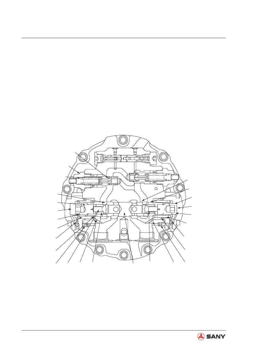
ZX215-1002096

Oil circuit B

Oil circuit C2

Orifice D3

Damper chamber A2

Orifice D4

Spring chamber 2

Oil circuit C1

Orifice D1

Damper chamber A1

Orifice D2

Spring chamber 1

6-2

7-2

5-2

4-2

2-2

2-1

4-1

5-1

7-1

6-1

8-2

8

8-1

3

1

M1

P1

P2

M2

D

Braking of motor 

The double-balanced valve and the relief valve forms the braking circuit.

When the main valve is in neutral position, hydraulic oil from the main pump is cut off, and
pressure at port P1 and P2 is the same. As a result, plunger (1) moves to the neutral position,
and the opening area of circuit B decreases.

At the same time, because of the inertia of external force, the motor does not stop rotating
(pump effect), and pressure at port M2 rises and serves as the braking force of motor rotation.

When the pressure at port M2 reaches the set pressure of relief valve (8), cone valve (8-1)
at port M1 overcomes the force of spring (8-2) and moves to the left, and hydraulic oil 

fl

 ows

to the port M1. In this way, the impacting force due to inertia at port M2 is under control, and
vacuum at port M1 is avoided.

Fig. 4-87 

4-97

Structure and Functions

SY365(B)H-9 Crawler Hydraulic Excavator

E. Shuttle valve function for high pressure selection 


The double-balanced valve can function as a shuttle valve to release travel brake. 


When hydraulic oil is fed to port P1, plunger (1) moves to the right, as shown in 

fi

 g. 4. At this 

time, drain passage F of motor housing is cut off, and passage D leading to cylinder chamber 
E for travel braking is opened. 


Hydraulic oil 

fl

 ows to passage G via the ori

fi

 ce, and enters travel brake cylinder chamber E to 

release the travel brake. In addition, plunger (1) moves to neutral position, as shown in 

fi

 g 5 

when motor stops. Passage D is closed and drain passage F of motor housing is opened. 


Hydraulic oil in travel braking cylinder chamber E is conducted to the drain passage of motor 
housing, and travel brake is applied. 

ZX215-1002097

Passage F

Passage D

Passage D

Passage D

Passage G

Passage G

Passage F

Cylinder chamber E

Orifice

1

ZX215-1002098

Passage F

Passage D

Passage D

Passage D

Passage G

Passage G

Passage F

Cylinder chamber E

Orifice

1

Fig. 4-88 

Fig. 4-89 

4-98

Structure and Functions

SY365(B)H-9 Crawler Hydraulic Excavator

ZX215-1002099

Travel control valve

10

22

A

12

13

14

11

M

ZX215-1002100

10

22

A

12

13

14

11

M

Travel control valve

4.6.9.2  Operation of parking brake

1) When starting travel


As the travel lever is operated, pressurized 
oil from the pump activates back pressure 
valve spool (10), opens the parking brake 
circuit, and flows to chamber A of brake 
piston (12). Pressurized oil overcomes the 
force of spring (11) and pushes piston (12) 
toward the left.


Since the pushing force to plate (13) and 
disc (14) disappears, plate (13) is sepa-
rated from disc (14) and the brake is re-
leased.

2) When travel is stopped


As the travel lever is placed in neutral, 
back pressure valve spool (10) returns to 
the neutral position and closes the parking 
brake circuit. T


he pressurized oil in chamber (A) of brake 
piston (12) passes through the orifice of 
the brake piston and is drained to the mo-
tor casing. Brake piston (12) is pushed to 
the right by spring (11). 


Plate (13) and disc (14) are pushed against 
each other, and the brake is applied. As 
brake piston (12) returns, a time delay is 
formed by making the pressurized oil pass 
through a throttle valve in the slow return 
valve (22). This time delay ensures an ac-
tive brake after the machine is stopped.

Fig. 4-90 

Fig. 4-91 

4-99

Structure and Functions

SY365(B)H-9 Crawler Hydraulic Excavator

ZX215-1002101

PA

MA

MB

8A

18

PB

Travel control valve

ZX215-1002102

PA

PB

MA

MB

8B

8A

19

Travel control valve

4.6.9.3  Operation of braking valve

The brake valve consists of a suction safe-
ty valve (8A) and a counterbalance valve
(18). As shown in the illustration on the
right, functions and operations of respec-
tive components are described below.

1. Counterbalance valve and check valve

Function

When traveling downhill, the weight of the
machine tends to make the travel speed
faster than the motor speed. If the machine
travels with the engine at low speed, the
motor may rotate at zero load, resulting
in runaway and inviting a very dangerous
situation. These valves are used to avoid
such a situation by controlling the machine
to travel according to the engine speed
(pump 

fl

 ow).

Operation when pressurized oil is supplied

Operating the travel control lever conducts
the pressurized oil from the control valve
to port (PA). The pressurized oil opens
suction safety valve (8A) and then 

fl

 ows to

motor outlet port (MB) via motor inlet port
(MA). The motor outlet side is closed by
suction safety valve (8B) and spool (19),
so the pressure at the supply side rises, as
shown in the right illustration.

Fig. 4-92 

Fig. 4-93 

4-100

Structure and Functions

SY365(B)H-9 Crawler Hydraulic Excavator

ZX215-1002103

PA

S1

19

E1 E2

PB

MA

MB

Travel control valve

ZX215-1002104

E2

E1

20

S1

19

PB

PA

MA

MB

Travel control valve

Brake operation in downhill travel

If the machine goes out of control while
travelling downhill, the motor will be caused
to rotate without load to decrease the inlet
side oil pressure. Pressure in chamber (S1)
drops via orifices (E1) and (E2). As the
pressure in chamber (S1) goes below the
spool shift pressure, spool (19) is returned
to the left by spring (20) and outlet port (MB)
is throttled. The pressure at the outlet port
side rises, generating rotation resistance
on the motor to prevent the machine from
losing control. On the other hand, the spool
moves to a position where the pressure on
outlet port (MB) can be balanced against
the machine's own weight and the inlet port
pressure. Oil 

fl

 ow from the outlet circuit is

reduced to ensure the travel speed corre-
sponded to the pump delivery, as shown in
the right illustration.

The pressurized oil on the supply side

fl

 ows to chamber (S1) via ori

fi

 ce (E1) and

ori

fi

 ce (E2) of the spool (19). As the pres-

sure in chamber (S1) goes above the spool
shift pressure, spool (19) is pushed toward
the right. Port (MB) and port (PB) are con-
nected, the motor outlet port side opens
and the motor starts rotating, as shown in
the right illustration.

Fig. 4-94 

Fig. 4-95 

4-101

Structure and Functions

SY365(B)H-9 Crawler Hydraulic Excavator

ZX215-1002105

MB

B1

A1

20

S1

PB

PA

MA

MB

Travel control valve

ZX215-1002107

MA

MB

Spool

2. Safety valve

Function


When the machine travel is stopped (or it 
is travelling downhill), the double-balanced 
valve closes the inlet and outlet circuits of 
the motor. Since the motor is rotated by 
inertial force, pressure in the motor outlet 
port side is abnormally increased, poten-
tially resulting in damages on the motor 
and piping. The safety valve relieves this 
abnormal pressure to the inlet port side of 
the motor in order to prevent damages to 
the equipment.

Operation

1) When travel is stopped (or when travelling 

downhill or swinging to the right)


Reduction of the pressure at motor inlet 
(PA) decreases the pressure in chamber 
(S1). When it drops beyond the spool shift 
pressure, the spool is returned to the left 
by spring (20), throttling the oil outlet pas-
sage (B1). At this time, the motor continues 
rotating due to its inertial force, thus pres-
sure on the outlet port (MB) is increased, 
as shown in the right illustration.


When the pressure rises above the set 
pressure of the suction safety valve (8A), 
the spool opens. The pressurized oil pass-
es through notch (A1) of the counterbal-
ance valve spool (19) into chamber (MA) of 
the circuit at the opposite side, as shown in 
the right illustration.

Fig. 4-96 

Fig. 4-97 

4-102

Structure and Functions

SY365(B)H-9 Crawler Hydraulic Excavator

ZX215-1002106

PA

S1

8A

19

E1

B2

8B

PB

MA

MB

Travel control valve

2) When starting travel (or traveling normally)

As the travel control lever is operated, the
pressurized oil from the pump moves the
counterbalance valve spool (19) toward
right. In this case, the passage to the suc-
tion safety valve functions as a circuit
which passes through notch (B2) of spool
(19), producing large differential pressure.
The pump pressure rises, providing a large
tractional force to the valve, as shown in
the right illustration.

3. Overload relief valve

The structure of the relief valve is shown
in the right figure. This valve is an area-
differential and direct-acting relief valve. It
has impact damping function during start-
ing and braking.

A. Operating principle and function

When the main control valve makes the
motor to start or brake, front pressure of
cone valve (2-9-2) rises above the set pres-
sure and the force of spring (2-9-5), and
moves cone valve (2-9-2) to the right and
off the valve seat (2-9-3). Pressurized oil in
the front of cone valve (2-9-2) is bypassed
to the low pressure side. The impact due
to inertia energy at the high pressure side
is put under control  and vacuum is pre-
vented from occurring at the low pressure
side through bypassing pressurized oil to
the low pressure side.

Fig. 4-98 

Fig. 4-99 

Fig. 4-100 

ZX365-1304108

ZX365-1304109

2-9-3

2-9-2

2-9-5

4-103

Structure and Functions

SY365(B)H-9 Crawler Hydraulic Excavator

ZX365-1304110

2-9-3

2-9-9

2-9-2

2-9-5

Area S2

Area S1

Spring chamber D

ZX215-1002111

O

Pressure (P)

Damping form

time (T)

B. Damping function


When the relief valve begins to function, 
damping piston (2-9-9) moves to the left. 
As a result, low pressure is maintained in 
spring chamber D. At this time, the loaded 
area of cone valve (2-9-2) is S1, and gen-
erally it is much larger than the set loaded 
area S1-S2 of the relief valve. So, when 
damping piston (2-9-9) is moving, the func-
tional pressure of relief valve is maintained 
at 1/3 of normal set pressure in order to 
absorb the impact at the high pressure 
circuit side due to inertial energy. When 
the movement of damping piston stops, 
pressure in spring chamber D rises. Pres-
sure at both side of cone valve (2-9-2) is 
the same, and the relief valve is working 
at normal set pressure. In this way, the re-
lief valve reduces the impact during motor 
starting and braking by a two-stage action 
to provide excellent performance.

Fig. 4-101 

Fig. 4-102 

4-104

Structure and Functions

SY365(B)H-9 Crawler Hydraulic Excavator

Table 2  Repair standard of motor components

Components

Check item

Allowable limit

Remedy

1-4-2 Plunger 
assembly

1. Boot sliding surface

Roughness 0.8a or surface rough-
ness, scratch 0.02mm+

Grind the boot sliding 
surface. Replace the 
cylinder block  assembly 
if the scratch cannot be 
corrected. 

2. Plunger outer diameter

Roughness 1.2a or surface rough-
ness, scratch 0.02mm+

Replace the cylinder 
block assembly. 

3. Plunger outer diameter
and cylinder block inner 
diameter

Clearance 0.060. 

4. Boot head clearance

Clearance 0.4. 

1-4-1 Cylinder 
block

1. Valve leaf and sliding sur-
face

Roughness 0.8a or surface rough-
ness, scratch 0.02mm+. 

Grind the boot sliding 
surface. Replace the 
cylinder block  assembly 
if the scratch cannot be 
corrected. 

2. Shaft hole inner diameter

Roughness 1.6a or surface rough-
ness, scratch 0.02mm+. 

Replace the cylinder 
block assembly

3. Shaft hole inner diameter
and  4-2 plunger assembly 
outer diameter

Clearance 0.060. 

4. Spline at shaft joint

Roller distance below 38.749 
(measuring pin diameter 

φ

3.333(V1=2.80)); or damaged

1-21 Oil distri-
bution plate

1. Sliding surface

Roughness 0.8a, scratch 0.02mm+ 
on sliding surface or burned sign

Grind the sliding surface. 
Replace the valve sheet 
if the scratch cannot be 
corrected.

1-4-3 Retainer
1-4-4 Retain-
ing assembly

1. Sliding surface

Roughness 0.8a, scratch 0.02mm+ 
on sliding surface or sign of burning

Replace the retaining 
plate or the retainer.

1-5 Swash 
plate

1. Sliding surface

Roughness 0.8a, abrasion on sling 
surface or scratch 0.02mm+

Grind the sliding surface. 
Replace the valve sheet 
if the scratch cannot be 
corrected.

2. Hole for assembling steel
ball

Roughness 1.6a. 

Replace the swash plate.

Scratch on spherical surface 
0.02mm+ or surface roughness

3. Hole for assembling steel
ball

Ball depth 14.5

4-105

Structure and Functions

SY365(B)H-9 Crawler Hydraulic Excavator

Components

Check item

Allowable limit

Remedy

1-3 Shaft

1. Oil seal sliding portion outer 
diameter

Roughness 1.6a, rough surface, or 
scratch 0.02mm+

Replace the swash 
plate.

2. Cylinder block matching
spline

Stick spans  below 47.380 (testing 
pin diameter 

φ

3.00), or the stick 

breakage. 

Replace the shaft.

3. Drive gear connection

Stick spans below 30.498 (testing 
pin diameter 

φ

3.33), or the stick 

breakage. 

1-15 Brake pis-
ton

1. Dimension

Height 38.2 

Replace the brake 
piston. 

2. Sliding surface

Roughness 2.5a 

3. Appearance

Scratch 0.02mm+ or rough surface  

1-13 Disc plate

1. Dimension

Thickness 3.2

Replace the disc 
plate.

2. Appearance

Deep scratch on sliding surface or 
friction material peeling

1-8 Ball bearing
1-9 Ball bearing

1. Rolling surface

Peeling or fracture

Replace the ball 
bearing.

2. Action

Abnormal rotation (noise•uneven 
rotation) 

1-7 Plunger as-
sembly

1. Boot sliding surface

Roughness 1.6a, rough surface, or 
scratch 0.02mm+

Grind the sliding 
surface. Replace the 

fl

 ange plate parts if 

the scratch cannot 
be corrected

2. Plunger outer diameter

Roughness 1.2a, rough surface, 
scratch 0.02mm+

Replace the 

fl

 ange 

plate parts.

3. Plunger outer diameter and

fl

 ange part inner diameter

Gap 0.040. 

4. Boot head clearance

Clearance 1.0

1-2-2 Plunger 
assembly

1. Plunger outer diameter

Roughness 0.8 a, scratch 0.02mm+ 
or rough surface 

Replace the valve 
sheet.

2. Plunger outer diameter and
valve sheet inner diameter

Clearance 0.060. 

1-2-1 Valve 
sheet

1. Assemble  the plunger as-
sembly hole

Roughness 0.8 a, scratch 0.02mm+ 
or rough surface

Replace the valve 
sheet and the parts.

2. Valve sheet inner diameter 
and plunger outer diameter

Clearance 0.060

3. Valve spool assembly instal-
lation hole

Roughness 0.8 a, scratch 0.02mm+ 
or rough surface

4. Spool valve sheet inner di-
ameter and valve spool outer 
diameter

Clearance 0.060. 

5. Movable plunger sliding part 
and seat of the relief valve

Scratch 0.02mm+ or surface rough-
ness

4-107

Structure and Functions

SY365(B)H-9 Crawler Hydraulic Excavator

Components

Check item

Allowable limit

Remedy

1-2-9 Spool as-
sembly

1. Valve spool out diam-
eter

Roughness 0.8 a, scratch 0.02mm+ 
or surface roughness

Replace valve sheet 
and parts

2. Valve spool outer diam-
eter and valve sheet inner 
diameter

Clearance 0.060. 

1-2-7-9 Movable 
plunger

1. Sliding portion of valve
sheet and valve seat

Scratch 0.02mm+ or surface rough-
ness

Replace relief valve 
assembly

1-2-7-1 Case

1. Sling portion of the
movable piston (outer 
diameter)

Scratch 0.02mm+ or surface rough-
ness

1-4-7 Spring

1. Dimension

Free length 61.0

2. Appearance

Deformation and surface damage

1-18 Spring

1. Dimension

Free length 39.0

2. Appearance

Deformation and surface damage

1-20 Spring

1. Dimension

Free length 41.5

2. Appearance

Deformation and surface damage

1-2-4 Spring

1. Dimension

Free length 48.5

2. Appearance

Deformation and surface damage

1-2-10 Spring

1. Dimension

Free length 28.3

2. Appearance

Deformation and surface damage

O-ring and oil seal

When removed

Replace o-ring and oil 
seal

4-108

Structure and Functions

SY365(B)H-9 Crawler Hydraulic Excavator

4.6.10 Control system

11

10

9

8

7

6

5

4

3

2

1

12

4

3

1

2

5

9

ZX365-1304112

6

12

11

13

10

7

8

Fig. 4-103 

4-109

Structure and Functions

SY365(B)H-9 Crawler Hydraulic Excavator

(1)  Pilot valve (travel)
(2)  Control lever (left travel)
(3)  Control lever (right travel)
(4)  Pilot valve (Right)
(5)  Control lever (right work equipment)
(6) Accumulator
(7) Block
(8) Hydraulic pump
(9)  Main control valve
(10) Solenoid valve
(11)  Control lever (left work equipment)
(12) Relay

Control lever positions

1

HOLD

2

Boom UP

3

Boom DOWN

4

Bucket DUMP

5

Bucket DIG

6

HOLD

7

Arm IN

8

Arm OUT

9

Right swing

10

Left swing

11

Neutral

12

Travel BACKWARD

13

Travel FORWARD

4-110

Structure and Functions

SY365(B)H-9 Crawler Hydraulic Excavator

4.6.11  Manual pilot valve

P: From pilot pump relief valve
P1: Left pilot valve: Arm OUT / Right pilot valve: Boom DOWN
P2: Left pilot valve: Arm IN / Right pilot valve: Boom UP
P3: Left pilot valve: Swing LEFT / Right pilot valve: Bucket DIG
P4: Left pilot valve: Swing RIGHT / Right pilot valve: Bucket DUMP
T: To tank

ZX365-1304113

1

2

3

4

P

P

P4

A

P1

A

P3

P2

T

64~73.5Nm

19~22Nm

Fig. 4-104 

4-111

Structure and Functions

SY365(B)H-9 Crawler Hydraulic Excavator

ZX215-1002114

10

9

8

7

6

5

4

3

2

1

A-A

(1) Plunger
(2) Adjusting spring
(3) Center spring
(4) Piston
(5) Disc

(6)  Nut (for control lever connection)
(7) Connector
(8) Plate
(9) Retainer
(10) Valve body

Fig. 4-105 

4-112

Structure and Functions

SY365(B)H-9 Crawler Hydraulic Excavator

Operation

1. When in neutral


Ports (A) and (B) of the control valve and 
ports (P1) and (P2) of the pilot valve are 
connected to drain chamber (D) via ori

fi

 ce 

(f) in plunger (1).

2. During 

fi

 ne control (Neutral to 

fi

 ne control)


When piston (4) is pushed by disc (5), 
retainer (9) is pushed, plunger (1) is also 
pushed by adjusting spring (2), and moves 
down. 


When ori

fi

 ce (f) is shut off from drain cham-

ber (D), it is almost simultaneously inter-
connected to pump pressure chamber (PP). 
Pilot pressurized oil of the control pump is 
led to port (A) from port (P1) via ori

fi

 ce (f). 

When the pressure at port (P1) becomes 
higher, plunger (1) is pushed back and 
orifice (f) is shut off from pump pressure 
chamber (PP). At almost the same time, it 
is connected to drain chamber (D) to re-
lease the pressure at port (P1). As a result, 
plunger (1) moves up and down until the 
force of adjusting spring (2) is balanced 
with the pressure at port (P1).


The relationship of the position of plunger 
(1) and body (10) [ori

fi

 ce (f) is in the middle 

between drain chamber (D) and pump 
pressure chamber (PP)] does not change 
until retainer (9) contacts plunger (1). Ad-
justing spring (2) contracts in proportion 
to the stroke of the control lever. Pressure 
at port (P1) also rises in proportion to the 
stroke of the control lever. In this way, the 
control valve plunger moves to a position 
where the pressure of chamber (A) (same 
as pressure at port (P1)) and the force of 
the return spring of the control valve plung-
er are balanced.

ZX365-1304115

A

M

M

B

P1

P

P2

f

1

T

D

Control valve

Pilot 

pump

Fig. 4-106 

ZX365-1304116

A

M

M

B

P1

P

P2

f

1

T

D

Control valve

Pilot 

pump

Fig. 4-107 


Content      ..     10      11      12      13     ..