SANY Crawler Hydraulic Excavator SY365H-9, SY365BH-9. Shop Manual (2014) - page 11
 

  Index      Manuals     SANY Crawler Hydraulic Excavator SY365H-9, SY365BH-9. Shop Manual (2014)


Search            copyright infringement  


Content      ..     9      10      11      12     ..


SANY Crawler Hydraulic Excavator SY365H-9, SY365BH-9. Shop Manual (2014) - page 11


4-80

Structure and Functions

SY365(B)H-9 Crawler Hydraulic Excavator

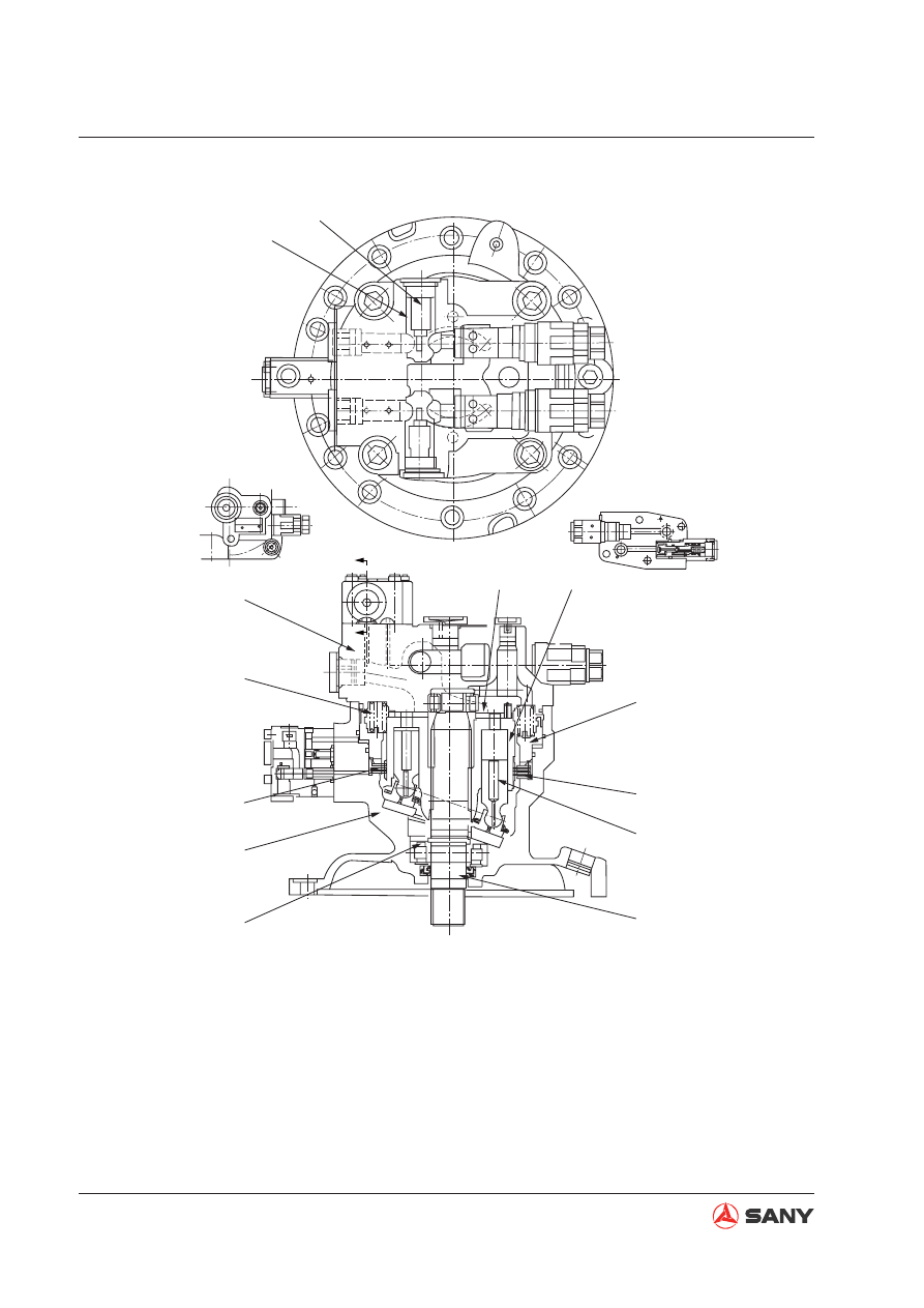
ZX215-1002082

A-A

12

13

8

1

5

4

3

11

2

9

6

7

10

A

A

(1) Spacer
(2) Housing
(3) Disc
(4) Brake spring
(5) Shell
(6) Spring
(7) Check valve

(8) Oil distributor
(9) Cylinder barrel
(10) Brake piston
(11) Plate
(12) Piston
(13) Drive shaft

Fig. 4-71 

4-81

Structure and Functions

SY365(B)H-9 Crawler Hydraulic Excavator

4.6.2  Swing holding brake


Port PG is directly connected with the pilot gear pump and it is always under a pressure of 
3.9MPa.

ZX215-1002083

a

5

1

6

7

M

PX

PG

SH

Pump

Main 
valve


Port SH is in connection with port (PX) of the main control valve. In case of any operation (ex-
cept travel) is performed by the main control valve, Port (PX) will be put under pressure. This 
pressure establishes connection between PG and chamber (a) below piston (7). The pres-
surized oil pushes the brake piston upward to compress spring (1) and separate disc (5) from 
plate (6). The brake is released. 

Fig. 4-72 

ZX215-1002084

a

5

1

6

7

M

PX

PG

SH

Pump

Main 
valve


Otherwise, without pressure acting upon the port (PX), the connection between (PG) and 
chamber (a) below piston (7) is blocked. Brake spring (1) pushes the brake piston to press 
disc (5) against plate (6). The brake is engaged. 

Fig. 4-73 

4-82

Structure and Functions

SY365(B)H-9 Crawler Hydraulic Excavator

4.6.3  Relief valve section

Structure


The relief valve section consists of relief valves (1) and (2) and check valves (3) and (4). 

Function


When the machine is in the swing holding mode, control valve (5) closes the motor outlet cir-
cuit, but the motor rotation is continued due to inertial force. The motor output is, therefore, 
abnormally increased, which could damage the motor.


In order to prevent the motor from being damaged, the relief valve relieves the abnormally 
high pressure oil to port (M) from the outlet side (high-pressure side) of the motor.

ZX215-1002085

1

2

3

C

A

B

5

4

From oil port M

Operating principle

1.  When starting swing (suppose pressurized 

oil is delivered to port A)


When the swing control lever is set to the 
right- swing, pressurized oil from the pump 
is delivered to port (A) via control valve (5).


The pressure at port (A) rises, the starting 
torque is generated in the motor, and the 
motor starts to rotate.


The pressurized oil from the outlet port of 
the motor passes from port (B) through the 
control valve (5) and returns to the tank.

Fig. 4-74 

4-83

Structure and Functions

SY365(B)H-9 Crawler Hydraulic Excavator

ZX215-1002086

1

2

3

C

5

4

A

B

From oil port M

2. When swing is stopped

When the swing control lever is set neutral,
the supply of pressurized oil from the pump
to port (A) is stopped.

The pressurized oil from the motor outlet
can't return to the tank since the returning
circuit to the tank is closed from control
valve (5). Thus, the pressure on port (B)
increases.

Swing resistance is generated on the mo-
tor and hence the brake starts working.

Pressurized oil will be relieved when the
pressure on port (B) rises to the set pres-
sure of relief valve (2).

A high braking torque acts on the motor,
thereby stopping the motor.

When relief valve (2) is being actuated, the
relieved oil and the pressurized oil from
port (M) are fed to port (B) via check valve
(4).

The above prevents the formation of cavi-
tation on port (B).

Fig. 4-75 

4-84

Structure and Functions

SY365(B)H-9 Crawler Hydraulic Excavator

4.6.4 Anti-jerk valve

4.6.4.1 Operation diagram

ZX215-1002087

T2

B

T1

A

1

2

3

7

6

5

4

B

A

T

Swing
motor

Swing Control Valve

(1) Valve body
(2) Spool (side A)
(3) Spring (side A)
(4) Plug
(5)  Spool (side B)
(6)  Spring (side B)
(7) Plug

4.6.4.2 Effect illustration

ZX215-1002088

: With antiswing valve

Without antiswing valve

Reversing pressure

Reversing pressure

Suppressing pressure

First reversing

Second reversing

Reverse

Start

Brake

Motor speed

Pressure MB

Pressure MA

Time

Fig. 4-76 

Fig. 4-77 

4-85

Structure and Functions

SY365(B)H-9 Crawler Hydraulic Excavator

ZX215-1002089

7

%

A

T

D1

c

d

㔎ষ

b f

e

D4 a D3

D2

ZX215-1002090

'

'

F

G 㔎ষ

E I

H

' D '

'

T

%

$

T

ZX215-1002091

2

b

d

3

a

f

5

T

A

B

T

Outline


The inertia of the swing body, the counter-
action and rigidity of the mechanical sys-
tem, or the compressibility of the hydraulic 
oil can cause shaking of machine during 
swing operation. The anti-jerk valve is able 
to reduce such impact. It is effective in pre-
venting collapsing of load when the swing 
is stopped and in reducing the cycle time 
(by better positioning performance and 
quicker movement for next operation).

Operation

1. When braking pressure is generated at  port 

(B)


Pressure (MB) is conducted to chamber (d) 
via the notch. The pressure compresses 
spring (6) by use of the difference in areas 
of circles (D1 > D2) of spool (5) and moves 
the spring (6) to the left side. Port (B) and 
chamber (e) will be interconnected. Since 
pressure (A) is lower than the set pressure 
of spring (3), spool (2) does not move and 
the pressurized oil is stopped by spool (2). 
Thus the braking force is ensured.

2. When motor is stopped


The motor rotation is reversed by the clos-
ing pressure generated at port (B). (1st 
reversing) Reversing pressure is gener-
ated on port (A) under the above condition. 
Pressure (A) is conducted to chamber (a), 
and spool (2) moves spring (3) to the right 
side, and A and B is interconnected. At this 
time, b is interconnected with f via the ori-
fice on spool (5), and reversing pressure 
on port A is bypassed to port T in order to 
prevent second reversing. 

Fig. 4-78 

Fig. 4-79 

Fig. 4-80 

4-86

Structure and Functions

SY365(B)H-9 Crawler Hydraulic Excavator

4.6.5  Central Swivel Joint

(1) Bolt
(2) O-ring 
(3) Cap
(4) O-ring
(5) Washer
(6) Collar
(7)  Rotary seal (CSI)
(8) Housing

(9) O-ring
(10) Swivel shaft
(11) Rotor
(12) Plug
(13) Bolt, socket-head
(14) Flat washer
(15) Dust boot

W365R130401

E

D

B

C

A

E

C

A

D

B

2

11

10

9

8

7

6

5

4

3

12

1

1314

15

Fig. 4-81 

4-87

Structure and Functions

SY365(B)H-9 Crawler Hydraulic Excavator

4.6.6 Travel motor

Type: MAG-170VP-3800E

View of motor before installation

Z

B

X

Bre

T

S

Y

M12×1.5

Torque 358Nm

Hexagon bolt
2-M20×40

Z

Direction B

B

A

MB

S

MA

Bre

X

M18×1.5

M18×1.5

Motor positioning cut

Φ

200H7

Oil inlet of brake

2-M20

Bolt hole for 
motor installation

Oil inlet of brake

Y

Oil inlet, level

Drain port

W365T130401

Fig. 4-82 

A, B: Working oil port

T: Oil drain port

MA, MB: Test port

S: Oil compensation port

X: Control pressure port

Bre: Oil port for releasing external brake

4-88

Structure and Functions

SY365(B)H-9 Crawler Hydraulic Excavator

Table 1 - Motor Speci

fi

 cations

Item

Unit

Speci

fi

 cations

Max input torque

N·m

546

Max input speed

r/min

4788

Max output torque

N·m

69309

Max output speed

r/min

37.7

Basic braking torque (without 

back pressure)

N·m

730

Starting pressure

bar

18

Max withstanding pressure

bar

50

Oil re

fi

 lling capacity

L

8.5

Speed ratio

-

126.94

Weight

kg

400

Brake disc

Disc type brake

Lubricant oil

220

40

℃)

industrial application

4-89

Structure and Functions

SY365(B)H-9 Crawler Hydraulic Excavator

4.6.7 Reducer

Type: GFT80

105

15 3 20 5 21 6 19 48 47 8 12 13

13 18 11 16 53 55 59 54 58 89 91 93

90 94 67 92 200 199

66

14

51

70

69

103

87

88

52

49

17

100

99

4

27

29

30

46

44

25

31

32

26

28

1

39

22

23

38

38 35

35

36

37

W365T130402

Fig. 4-83 

4-90

Structure and Functions

SY365(B)H-9 Crawler Hydraulic Excavator

No.

Code Description

Qty

E001

R988011946

Support shaft 

1

E003

R988012090

Drive shaft    

1

E004

R988011553

Planetary carrier   

1

E005

R988012073

Bearing seat 

1

E006

R916452282

Collar

1

E008

R916452408

Collar         

1

E011

R988011587

Planetary gear

5

E012

R916411696

Cylidrical roller 
bearing

10

E013

R988012373

Collar

10

E014

R916452254

Collar

5

E015

R988013065

Float seal    

1

E016

2916650025

Elastic collar  

5

E017

R988011192

Sun gear   

1

E018

R916452068

Elastic collar  

1

E019

R988011289

Round nut

1

E020

R916412778

Tapered roller 
bearing

1

E021

R916412722

Tapered roller 
bearing

1

E022

R988012516

 O-ring    

1

E023

R913006409

Bolt, hexagon    

2

E025

R988011598

Piston        

1

E026

R988012185

Collar

1

E027

R988012320

Collar

2

E028

R916452300

Collar

1

E029

R988012929

Friction disc, 
outside  

6

E030

R988012931

Friction disc, 
inside  

5

E031

R916423354

Spring       

18

E032

R916423355

Spring       

18

E035

R988012913

Collar 2

E036

R988012397

Spring sleeve  

1

E037

R988012404

X -ring

1

E038

R988012914

X -ring

2

E039

R902602007

Plug

1

E044

2917890148

Pin  

2

E046

R988012493

O-ring

1

E047

R988011215

Bearing seat

1

No.

Code Description

Qty

E048

R913006477

Bolt, hexagon 

24

E049

R988010958

Gear ring 

1

E051

R988011457

End cover 

1

E052

R988011597

Sun gear   

1

E053

R988011951

Planetary carrier

1

E054

R988011483

Planetary  gear       

3

E055

R988012459

Cylindrical roller 
bearing

3

E058

2916650023

Collar

3

E059

R913003909

Collar  

1

E066

R988012492

Ring 1

E067

R913006441

Bolt, hexagon 

12

E069

R913003865

Plug

2

E070

R916462052

Washer

2

E087

R988011630

Sun gear   

1

E088

R988012341

Collar

1

E089

R988011188

Planetary carrier

1

E090

R988011840

Planetary gear

3

E091

R988012458

Cylindrical roller 
bearing

3

E092

R916452026

Collar

3

E093

R916462507

Collar

6

E094

R916452244

Collar

6

E099

R988012398

Deep-grooved 
ball bearing

1

E100

R916462138

Collar

1

E103

R988012357

Cylidrical roller

1

E105

R902165278

Motor

1

E199

R988012436

Rivet

4

E200

R909830326

Nameplate

1

4-91

Structure and Functions

SY365(B)H-9 Crawler Hydraulic Excavator

4.6.8  Travel motor (Nabtesco)

Type: GM60VA

Fig. 4-84 

A: Main oil port

B: Main oil port

Am: Pressure detection port

Bm: Pressure detection port

Pi: Two-speed pilot tubing port

Dr: Oil drain port

26XM20 18XM24

Filling port

Drain port

Dr

Pi

MA

A

B

MB

ZX305-1102601

Nabtesco

Nabtesco

FILL
lEVEL

DRAIN

4-92

Structure and Functions

SY365(B)H-9 Crawler Hydraulic Excavator

Item

Unit

Speci

fi

 cations

Input 

fl

 ow

L/min

280

Relief valve pressure setting

Mpa

34.3

Motor displacement

cm

2

/rev

290.7/170.1

Reduction ratio

40.67

Total displacement

cm

2

/rev

Theoretical output torque

KN

·m

64.3/37.6

Theoretical output speed

r·p·m

23.8/40.7

Braking torque

KN

·m

1.17

Brake release pressure

Mpa

1.54

Auto switching pressure

Mpa

26.5

Operating temperature range

-20~90

Total weight

kg

399

4-93

Structure and Functions

SY365(B)H-9 Crawler Hydraulic Excavator

4.6.9  Operating principle of the basic components

4.6.9.1 Double-balanced valve

Function:


When external load makes the plunger motor tend to go faster than the rated rotating speed 
of feed 

fl

 ow (hereunder referred to pump effect), this valve controls motor speed and prevents 

over-speed of the motor in relation with the feed 

fl

 ow.


The double-balanced valve and the relief valve constitute the braking circuit. The braking cir-
cuit applies braking force onto the swing of plunger motor and stops the motor gradually.


This valve can serve as a shuttle valve for high pressure selection to release the brake under 
its own pressure.


The structure of a standard double-balanced valve is shown below. The following information 
describes the operating principle of a standard double-balanced valve.

A. When stopped


When the main valve is neutralized (motor stopped), port M1 and port M2 are shut off by 
spool (1) and check valve (2) since no pressure is generated at port P1 and port P2. The mo-
tor is not rotating.

ZX215-1002094

Oil circuit B

Oil circuit C2

Orifice D3

Damper chamber A2

Orifice D4

Spring chamber 2

Oil circuit C1

Orifice D1

Damper chamber A1

Orifice D2

Spring chamber1

6-2

7-2

5-2

4-2

2-2

2-1

4-1

5-1

7-1

6-1

8-2

8

8-1

3

1

M1

P1

P2

M2

Fig. 4-85 

4-94

Structure and Functions

SY365(B)H-9 Crawler Hydraulic Excavator

B. When motor is started

When the hydraulic oil from the main pump enters port P1 of the double-balanced valve,
spring (3) is pushed to the left by check valve (2-1), opening circuit C1. The hydraulic oil en-
ters the plunger motor via port M, trying to make the motor rotating. At the same time, return
oil from the plunger motor enters the counterbalance valve via port M2, but it is stopped by
check valve (2-2). The output pressure of the main pump increases as a result, and the hy-
draulic oil works on the inside of spring chamber (1) and damper chamber (A1) via ori

fi

 ce (4-1)

and check valve (5-1). The force generated in this way pushes spring (7-2) on the other side
and moves plunger (1) to the right. At this time, return oil from port M2 passes through circuit
of the notch on the periphery of plunger (1), and through port P2 when pressure is generated
at port M2, and enters the tank via the main valve 

fi

 nally. The motor starts rotating at this time.

ZX215-1002095

Oil circuit B

Oil circuit C2

 Orifice D3

 Damper chamber A2

 Orifice D4

Spring chamber 2

Oil circuit C1

Orifice D1

Damper chamberA1

Orifice D2

Spring chamber 1

6-2

7-2

5-2

4-2

2-2

2-1

4-1

5-1

7-1

6-1

8-2

8

8-1

3

1

M1

P1

P2

M2

Fig. 4-86 

4-95

Structure and Functions

SY365(B)H-9 Crawler Hydraulic Excavator

C. Counterbalance function


When the engine runs at an excessively high speed because of external force applied on it, 
the motor may lose control. At this time, port P1 serves as the inlet side, and the pressure 
drops. Pressure in spring chamber (1) and damper chamber A1 also drop. As a result, plunger 
(1) moves to the left under the force of spring (7-2), closing circuit B. Circuit at the suction 
side is also closed at the same time when the circuit at return side is closed. When circuit B is 
closed, pressure at port P1 rises due to hydraulic oil from the main pump, moving plunger (1) 
to the right again. In this way, when external load generates pump effect, slight movement of 
plunger (1) keep circuit B open. The rotation speed of the motor keeps in line with fuel supply 
of the main pump, and the motor will not lose control because of the vacuum in the hydraulic 
system.


Content      ..     9      10      11      12     ..