SANY Crawler Hydraulic Excavator SY365H-9, SY365BH-9. Shop Manual (2014) - page 9
 

  Index      Manuals     SANY Crawler Hydraulic Excavator SY365H-9, SY365BH-9. Shop Manual (2014)


Search            copyright infringement  


Content      ..     7      8      9      10     ..


SANY Crawler Hydraulic Excavator SY365H-9, SY365BH-9. Shop Manual (2014) - page 9


4-48

Structure and Functions

SY365(B)H-9 Crawler Hydraulic Excavator

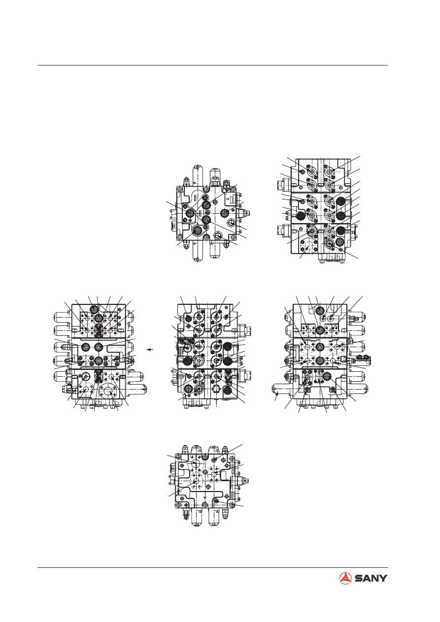
4.5  Hydraulic system, Part 2

4.5.1  Main control valve

4.5.1.1 Overview 

+

(PTb)

(PTb)

(PTa)

XAtL

XBb1

XBa1

(P4)

(P3)

(R4)

Rs1

Rs2

CCo

CCk

PaL,Dra

XBa2

XBp2

XAc

PAcs

PbL,Drb

XAa1

P2  CUT

XBtr

XBtL

LCAT2

LCAP2

 A

N1

N2

BtL

AtL

CP1 CT1 CMR1 CMR2

XAb1

XBc

XAa2

P1 CUT

XBp1

Bc

(HEAD)

Ab

(HEAD)

(Ba2)

(HEAD)

Bb

(ROD)

Ac

(ROD)

(PTa) XAtr

Pns,Dr4

PG

R3

P2

P1

PH

XBtr

XAs

XAtr

Pns

Dr4

Pna1

Dr3

XBb2

(XAo)

XBa1

ARC

Dra

PaL

ࡼ㞖

2

ে㸠䍄

Ⳉ㒓㸠䍄

Ꮊ㸠䍄

ࡼ㞖

1

䫆᭫

ࡼ㞖

2

ಲ䕀

᭫ᴚ

1

OPTION

XBs

HVa

Bs

CT2 CP2 Pns

LCs

Dr4

As

Btr

Atr

XAb2

XAb2

XAb1

(XBo)

XBc

XAa1

XAa2

BbR

BcR

BaR

(R2)

XBp1

BoR

XBs

XBtL

XBtr

Px

(PTb)

(XBo)

(Bo)

Ba1

R1

Dr3

LCa Pra1

(HEAD)

XAa1

XBp1

LCb2

CCb

LCo

Aa

(ROD)

(Ao)

XBp2

Pna1,Dr3

XBp1

Pns

Dr4

Dr2

Pna1

Dr3

XBb2

XBb1

(XAo)

AcR

XBa1

XBa2

AbR

AoR

AaR

XBp2

MR

PbL

XAs

XAtL

XAtr

Py

P2

A

(PTa)

Hvb

Drb

Dra

PaL

Dr1

W365V130701

LCb

LCk

Fig. 4-43 

4-49

Structure and Functions

SY365(B)H-9 Crawler Hydraulic Excavator

P1

P2

Aa

Ba1

(Ba2)

Ab

Bb

Ac

Bc

Atr

Btr

AtL

BtL

As

Bs

XAtr

XBtr

XAtL

XBtL

XAs

XBs

XBb1

XAb1

XBb2

XAb2

XBa1

XAa1

XBa2

XAa2

XAc

XBc

XBp1

XBp2

: Pump port (P1 side)

: Pump port (P2 side)

: Rod end port, arm cylinder (OUT)

: Head end port, arm cylinder (IN)

: Head end port, arm cylinder (IN)

: Head end port, boom cylinder (UP)

: Rod end port, boom cylinder (DOWN)

: Rod end port, bucket cylinder (DUMP)

: Head end port, bucket cylinder (DIG)

: Motor port, right travel

: Motor port, right travel

: Motor port, left travel

: Motor port, left travel

: Motor port, swing

: Motor port, swing

: Pilot port, right travel

: Pilot port, right travel

: Pilot port, left travel

: Pilot port, left travel

: Pilot port, swing

: Pilot port, swing

: Pilot port, boom 1 (DOWN)

: Pilot port, boom 1 (UP)

: Pilot port, boom con

fl

 uence (DOWN)

: Pilot port, boom con

fl

 uence (UP)

: Pilot port, arm 1 (IN)

: Pilot port, arm 1 (OUT)

: Pilot port, arm 2 (IN)

: Pilot port, arm 2 (OUT)

: Pilot port, bucket (DUMP)

: Pilot port, bucket (DIG)

: Pilot port, bypass stop valve spool (P1 
side)

: Pilot port, bypass stop valve spool (P2 
side)

PAcs

Pna1

Pns

PG

PH

Pz

PaL

PbL

Px

Py

Drl

Dr2

Dr3

Dr4

Dra

Drb

R1

(R2)

R3

Rs1

Rs2

(Ao)

(Bo)

(XAo)

(XBo)

(PTa)

(PTb)

(N1)

(N2)

(P3)

(P4)

(R4)

: Pilot port, bucket (DIG) travel limit

: Pilot port, arm 1 logic control valve

: Pilot port, swing logic control valve

: Pilot pressure source port

: Pilot pressure source port

: Pilot pressure for boosting main relief valve

: Pilot port, lock valve (arm rod end )

: Pilot port, lock valve (boom head end)

: Signal port used for work equipment

: Signal port used for travel

: Oil drain port

: Oil drain port

: Oil drain port

: Oil drain port

: Oil drain port

: Oil drain port

: Oil return port

: Oil return port

: Oil return port

: Oil re

fi

  lling port

: Oil re

fi

  lling port

: Backup port

: Backup port

: (Backup pilot port)

: (Backup pilot port)

4-50

Structure and Functions

SY365(B)H-9 Crawler Hydraulic Excavator

4.5.1.2  Main valve structure

MR

Pz

Drb

Hvb

AcR

Dr1

PbL

XBp2

Py

Pns

Pna1

PaL

AaR

Dr4

Dr3

Dra

AbR

AoR

PbL Drb

P-P

B

A

J

992×2

101

102

252

991

252

103

Dra

PaL

Q-Q

151

167

151
167

MR

Pz

N-N

151

167

PG

L-L

152 168

351

151
541

542
554

166

543
151
167

167

CCo

CCk

M-M

521
551

561
169
153
551

521

561

515

515

N

N

Q

Q

B

A

D

C

E

P

F

G

H

C

A

971×6

(PTb)

R3

PG

PH

P2

P1

XBtr

(PTa)

XAtr

L

L

D

E

F

G

H

+

C

(P4)

(P3)

(R4)

Rs1

Rs2

CCo

CCk

XAa1

XBp1

XBp2

XBa1

PaL,Dra

971×6

273×4

211

M

M

P

W365V130704

Straight travel

Left travel

Boom 1

Bucket 

Arm 2

P2 stop

Right travel

Swing

Boom 2

Backup

Arm 1

Arm regeneration stop

Direction J

Fig. 4-44 

4-51

Structure and Functions

SY365(B)H-9 Crawler Hydraulic Excavator

351

PH

PG

XBtr

XBs

XAb2

XAa1

(R2)

Rs2

Rs1

(P4)

(XBo)

(PTa)

XAtL

XBb1

XBa2

XBp2

(PTb)

R3

P1

XBtL

XAb1

XAa2

XBc

XBp1

XAtr

XAs

XBb2

XBa1

A-A

B-B

(XAo)

271×2

271×2

271×2

P2

152

168 169 153

271×2

271×2

271×2

271×2

271×2

271×2

341

168

153

169

271×2

271×2

271×2

271×2

271×2

271×2

272×2

162

561

561

551

551 163

162

271×2

271×2

271×2

271×2

272×2

W365V130705

Fig. 4-45 

4-52

Structure and Functions

SY365(B)H-9 Crawler Hydraulic Excavator

153

201
336

332

373

337

332

261

301

561

511

511

263

203

521

521

551

551

561

169

201

336

332

372
337

332

261
601
308
512
522
552

562

CMR2

MR

Pta

XAtr

CMR1

CT1

512

522

552

562
561

551
521
511

263
203

169

153

201

166

166

336

332

373

337
332
261

201
336

332

371

337
332
261

301
166
165

165
161

163

305
162

263
203

256
254

263
203

511

521

551
561

XAs

As

Pns

Bs

LCs

XAtL

AtL

CP1

BtL

XBs

XBtL

XBtr

Px

Btr

CP2

CT2

Atr

Py

(PTb)

W365V130705

Section C-C

Left travel

Swing

Section D-D

Straight travel

Right travel

Fig. 4-46 

4-53

Structure and Functions

SY365(B)H-9 Crawler Hydraulic Excavator

201
336

332

373

337

332
261

561
523
513

553

303

551
561

511

521

551

551

521

561

511

561

201
336

332

371

337

332
602
261

307

165

163

263

602

203

263
203

XBb1

Hvb

Ab

Boom 1

Boom 2

Section E-E

XBb2

AbR

CCb

Lcb2

LCb

BbR

Bb

XAb2

XAb1

Dr2

153

169

201
336

332

371
337

332
261
309
605

166

166

275×4

275×4

264
213
511

521

551

561
264
213

605

263

203
169
153

555

563

204
342
336

332
371
337

332

261
602
304
162
164
165
163

511

521

551
561
164
161

602

263
203

LCk

Section F-F

Bucket

Backup

(XAo)

AoR

(Ao)

LCo

Bo

BoR

BcR

Bc

Ac

XBc

(XBo)

XBa2

PAcs

XAc

AcR

W365V130706

Fig. 4-47 

4-54

Structure and Functions

SY365(B)H-9 Crawler Hydraulic Excavator

561

551

262

331

334

323

324

331

333

202

277×4

257

602

267

215

333

331

324

152

168

202

323

334

331

262

551

561

169
153

169

153

310

310

Section H-H

P2 stop

P1 stop

Arm regeneration stop

XBp2

XBp1

AaR

Aa

CCk

CCo

R1

(R2)

(N1)

(N2)

514

201
336
332

375

337
332
261
306

201
336
332
371

337
332
261

302
167

275×4

276×4

511

521

551

285
266

263

203

264
602

205

261

214

214

531
522

153
169

561

151

553

561

513

523

253

255

Section G-G

Arm 2

Arm 1

XBa1

Dra

Hv6

LCa

Pna1

Ba1

XAa1

XAa2

XBa2

Dr1

Ba2

BaR

LCAT2

W365V130707

Fig. 4-48 

4-55

Structure and Functions

SY365(B)H-9 Crawler Hydraulic Excavator

No.

Part name

Qty

Torque

N.m

No.

Part name

Qty

Torque

N.m

101

Valve body A

1

305

Swing spool

1

102

Valve body B

1

306

Spool, arm 2

1

103

Valve body C

1

307

Spool, boom 2

1

151

Oil plug

6

13~17

308

Spool AS, straight 

travel

1

152

Oil plug

2

34~39

309

Backup

1

153

Oil plug

10

69~78

310

Spool, bypass stop

2

161

O-ring seal

4

323

Spring

2

162

O-ring seal

6

324

Spring

2

163

O-ring seal

9

331

Spring seat

4

164

O-ring seal

2

332

Spring seat

20

165

O-ring seal

4

333

Bolt with washer

2

16~18

166

O-ring seal

12

334

Stopper

2

167

O-ring seal

6

336

Bolt with washer

10

37~41

168

O-ring seal

3

337

Stopper

10

169

O-ring seal

10

341

Oil plug

1

34~39

201

Spring cap

9

342

Piston

1

202

Spring cap

2

351

节流塞(φ

0.7

3

7.8~9.8

203

Spool cap

9

371

Spring

8

204

Spring cap

1

372

Spring

1

205

Spool cap

1

375

Spring

1

211

Plate

1

511

Cone valve

10

213

Flange

2

512

Cone valve

2

214

Check valve plate

1

513

Cone valve

2

275

Pipeless opening cover

plate

1

514

Cone valve

1

216

Pipeless opening cover

plate

1

515

Cone valve

2

252

Lock valve selector GP

2

9.8~14

521

Spring

12

253

Logic valve component,

arm 1

1

522

Spring

3

254

Logic valve component,

swing

1

523

Spring

2

255

Logic control valve

2

52~62

531

Spring seat

1

257

Stop valve GP, arm 

regeneration

1

120~140

541

Steel ball

1

261

O-ring seal

11

542

Spring seat

1

262

O-ring seal

2

543

Spring

1

263

O-ring seal

9

551

Oil plug

17

370~410

264

O-ring seal

3

552

Oil plug

2

230~260

265

O-ring seal

1

553

Oil plug

2

370~410

266

O-ring seal

1

554

Oil plug

1

25~29

267

O-ring seal

1

555

Oil plug

1

220~260

271

Bolt, socket head

40

52~62

561

O-ring seal

19

272

Bolt, socket head

4

25~34

562

O-ring seal

2

273

Bolt, socket head

4

210~260

563

O-ring seal

1

275

Bolt, socket head

12

140~180

601

Main relief valve

1

120~140

276

Bolt, socket head

4

25~34

602

Port relief valve

6

120~140

277

Bolt, socket head

4

83~110

605

Port relief valve

2

120~140

301

Travel spool

2

971

Bolt, socket head

12

390~470

302

Spool GP, arm 1

1

991

Nameplate

1

303

Spool GP, boom 1

1

992

Rivet

2

304

Bucket spool

1

4-56

Structure and Functions

SY365(B)H-9 Crawler Hydraulic Excavator

4.5.2 Hydraulic circuit 

(With bucket con

fl

 uence function)

W365V130703

Travel (R)

Swing

Bypass stop

Arm 2

Bucket

Straight travel

Travel (L)

Boom 1

Arm 1

Backup

Boom 2

Fig. 4-49 

4-57

Structure and Functions

SY365(B)H-9 Crawler Hydraulic Excavator

Operating principle

1) When spool is neutral position

(Main circuit)


When all spools are in neutral position, the working oil from (front) hydraulic pump enters the 
pump port P1, is guided to the main oil passage (1), and returns to the oil tank via the return 
ports R1 and R3 by passing through the neutral bypass (2) (function of neutral M-shaped 
spool) of each spool in straight travel (308), left travel (301), boom 1 (303), bucket (304) and 
arm 2 (306).


The working oil from (rear) hydraulic pump enters the pump port P2, is guided to the main 
oil passage (3), and returns to the oil tank via the return ports R1 and R3 by passing through 
the neutral bypass (4) (function of neutral M-shaped spool) of each spool in right travel (301), 
swing (305), boom 2 (307), backup (309) and arm 1 (302).

4-58

Structure and Functions

SY365(B)H-9 Crawler Hydraulic Excavator

R3

P1

(1)

(PTb)

(PTa)

XBtL

XAtL

XAb1

XBb1

XAa2

XBa2

XBp2

XBp1

XAtr

XAs

XBb2

XBtr

XBs

XAb2

XBa1

(XAo)

(XBo)

(p4)

(p3)

Rs1

Rs2

(R2)

XBc

(2)

(3)

(4)

PH

P2

PG

WJV3651305

Fig. 4-50 

4-59

Structure and Functions

SY365(B)H-9 Crawler Hydraulic Excavator

2) Travel

(Pilot circuit)

When switched to left travel spool or right travel spool, the side oil passage closes and the
pressure in port Py (travel signal port) rises.

(Main circuit)

When pressure is present in pilot port XBtL used for left travel spool (301), the neutral bypass
(2) at the side of boom 1 closes. The working oil fed from (front) hydraulic pump is delivered
through port BtL to the left travel motor.

Likewise, when pressure is present in pilot port XBtr used for right travel spool (301), the neu-
tral bypass (2) at the side of arm 1 closes. The working oil fed from (rear) hydraulic pump is
delivered through port Btr to the right travel motor.

On the other hand, the oil returning from both the left and right travel motors via port AtL (Atr)
passes the left (right) travel spool and goes back to the oil tank via return ports R1 and R3.

When operating travel in the opposite side (pressurizing the pilot ports XAtr and XAtL), the
above principle also applies.

XBtL

XAtL

AtL

BtL

Travel motor

WJV3651306

Fig. 4-51 

4-60

Structure and Functions

SY365(B)H-9 Crawler Hydraulic Excavator

3) Arm

Arm-out operation

(Pilot circuit)

When switched to the arm 2 spool (302), the side oil passage closes and the pressure in port
Px (work equipment signal port) rises.

(Main circuit)

When performing the arm-out operation, the pilot oil is fed to port XAa1 and port XAa2. When
pilot oil is delivered to the two sides of port XAa1 and port XAa2, arm 1 spool and arm 2 spool
are switched to the left, as shown in Fig. 4-52. As a result, the working oil from port P2 is in-
troduced into the neutral bypass (4) via the main passage (3). The neutral bypass is cut off
by switching the arm 1 spool (302). Therefore, the working oil in the parallel passage pushes
open the cone valve (253) of the logic valve, and enters the arm 1 spool (302) via the U pas-
sage. The oil from arm 1 spool (302) is then delivered to the rod end (R) of arm cylinder.

On the other hand, the working oil coming from port P1 is guided to the neutral bypass (2)
via the main oil passage (1). The neutral bypass is cut off by switching the arm 2 spool (306).
Therefore, the working oil in the parallel passage pushes open the cone valve (514) of logic
valve, and working oil from neutral bypass pushes open the cone valve (511) of the check
valve and 

fl

 ows into the arm 2 spool (306) via the U passage. The oil then comes into con

fl

 u-

ence with oil from port Aa in the passage of neutral bypass (306) and is fed to the rod end (R)
of the arm cylinder.

Return oil from the arm cylinder head end (H) via port BaI 

fl

 ows respective tank circuits of arm

1 and arm 2, and returns to working oil tank via tank ports R1 and R3.

4-61

Structure and Functions

SY365(B)H-9 Crawler Hydraulic Excavator

XBa2

Dr1

XBa1

511

514

LCAT2

(Ba2)

BaR

XAa2

XAa1

Ba1

LCa

Pna1

253

Aa

Dra

R

H

WJV3651307

Fig. 4-52 

4-62

Structure and Functions

SY365(B)H-9 Crawler Hydraulic Excavator

Arm-in operation

(Pilot circuit)

When switched to the arm 1 spool (302), the side oil passage closes and the pressure in port
Px (work equipment signal port) rises. Pressurized oil is fed to the port PaL at the same time.
Relief signal is sent to the lock valve selector GP (252).

(Main circuit)

When performing the arm-in operation, pilot oil is fed to ports XBa1 and XBa2. When pilot oil
is delivered to the two sides of port XBa1 and port XBa2, arm 1 spool and arm 2 spool are
switched to the right as shown in Fig. 4-53. As a result, working oil from P2 is guided to the
neutral bypass (4) via the main passage (3). The neutral bypass is cut off by switching arm
1 spool (302). Therefore, the working oil in the parallel passage pushes open the cone valve
(253) of the check valve and 

fl

 ows to the arm 1 spool (302) via the U passage. Then, it 

fl

 ows

to the periphery of arm 1 spool (302) and is delivered to the arm cylinder head end (H) via
port Ba.

On the one hand, the working oil from port P1 is guided to the neutral bypass (2) via the main
passage (1). The neutral bypass is cut off by switching the arm 2 spool (306). Therefore,
the working oil in the parallel passage pushes open the cone valve (514) of the arm 2 check
valve, and the working oil from neutral bypass pushes open the cone valve (511) of the check
valve and 

fl

 ows to the arm 2 spool (306) via the U passage. Then, it comes into con

fl

 uence

with oil from port BaI in the internal passage of arm 2 spool (306).

On the other hand, the oil returning from the arm cylinder rod end (R) and the working oil
whose pressure rises due to the dead weight of arm goes back to the port Aa. The working oil
returned to the port Aa 

fl

 ows into the valve spool via the holes (a) on the periphery of arm 1

spool (302), pushes open the cone valve (302-317) only under light load, and comes into con-

fl

 uence in the peripheral holes with oil from port BaI.

If the pressure at the arm cylinder head end and in the U passage rises, arm regeneration
check valve spool (257-103) switches to the left, as shown in Fig. 4-54, and closes due to
the back pressure of the cone valve (302-317) in the spool. In this way, the arm regeneration
function is deactivated and return oil from the arm cylinder rod end (R) 

fl

 ows to the spool via

the hole (a) on the periphery of arm 1 spool (302). Then, it 

fl

 ows into arm regeneration stop

valve (257) via hole (c) on the periphery of arm 1 spool (302), and returns to the working oil
tank via tank ports R1 and R3.

4-63

Structure and Functions

SY365(B)H-9 Crawler Hydraulic Excavator

XBa2

Dr1

XBa1

LCAT2

(Ba2)

BaR

XAa2

XAa1

Ba1

LCa

Pna1

Aa

Dra

R

H

(302-317)

Arm dead weight

(b)

(a)

WJV3651308


Light load

Fig. 4-53 


Content      ..     7      8      9      10     ..