SANY Crawler Hydraulic Excavator SY365H-9, SY365BH-9. Shop Manual (2014) - page 8
 

  Index      Manuals     SANY Crawler Hydraulic Excavator SY365H-9, SY365BH-9. Shop Manual (2014)


Search            copyright infringement  


Content      ..     6      7      8      9     ..


SANY Crawler Hydraulic Excavator SY365H-9, SY365BH-9. Shop Manual (2014) - page 8


4-32

Structure and Functions

SY365(B)H-9 Crawler Hydraulic Excavator

ZX215-1002021

1

4

5

7

B

X

a

A

ZX215-1002022

4

5

6

7

E

X

a

F

A

ZX215-1002023

7

4

E

F

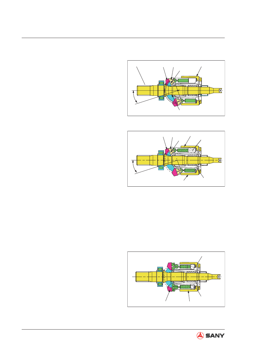
4.4.3.4 Operating principle

Cylinder block (7) rotates together with
shaft (1), and slipper (5) slides on 

fl

 at sur-

face (A).

When this happens, swash plate (4) moves
along cylindrical surface (B), so angle (a)
between central line (X) of swash plate (4)
and the axial direction of cylinder block (7)
changes.

(a) stands for the angle of the swash plate.

With central line (X) of swash plate (4) at
a swash plate angle (a) in relation to the
axial direction of cylinder block (7), 

fl

 at sur-

face (A) acts as a cam in relation to slipper
(5).

In this way, plunger (6) slides on the in-
side of cylinder block (7), so a difference
between volumes (E) and (F) is created
inside cylinder block (7).

A single plunger sucks and discharges the
oil by the amount (F) – (E).

As cylinder block (7) rotates and the vol-
ume of chamber (E) becomes smaller, the
pressurized oil is discharged.

On the other hand, the volume of chamber
(F) grows larger and, in this process, the
oil is sucked in.

As central line (X) of swash plate (4) over-
laps the axial direction of cylinder block (7)
(swash plate angle (a) = 0), the difference
between volumes (E) and (F) inside cylin-
der block (7)becomes 0.

Suction and discharging of pressurized
oil is not carried out in this state. Namely
pumping action is not performed. (In real-
ity, however, the swash plate angle is not
set to 0)

Fig. 4-19 

Fig. 4-20 

Fig. 4-21 

4-33

Structure and Functions

SY365(B)H-9 Crawler Hydraulic Excavator

ZX215-1002024

13

4

a

16

F

E

4.4.3.5  Oil delivery control


If swash plate angle (a) becomes larger, 
the difference between volumes (E) and 
(F) becomes larger and pump delivery (Q) 
increases.


Piston (13) is used for changing swash 
plate angle (a).


Piston (13) makes linear reciprocal move-
ment under the control of the regulator.


This linear motion is transmitted to swash 
plate (4) via drive pin (16). The sliding of  
the swash plate changes the swash plate 
angle and changes the displacement of the 
main pump. 

Fig. 4-22 

4-34

Structure and Functions

SY365(B)H-9 Crawler Hydraulic Excavator

4.4.4 Pilot pump

ZX215-1002025

710

435

433

700

434

355

354

310

351

732

311

312

309

307

308

434 850

466

725

435

361

353

307: Valve stem
308: Valve base
309: Retainer
310: Spring
311: Adjusting screw
312: Nut
351: Body
353: Gear shaft
354: Gear shaft
355: Filter element

361: Body
433: Screw
434: Screw
435: screw
466: Plug
700: Washer
710: O-ring
725: O-ring
732: O-ring
850: Washer

Function

The engine drives the main pump shaft and the pilot pump shaft through the gearbox. The pilot 
pump is operated through gear engagement.  

Fig. 4-23 

4-35

Structure and Functions

SY365(B)H-9 Crawler Hydraulic Excavator

4.4.5 Regulator 

W365P130701

438

646

079

B-B

418

496

439

B

413

757

438

656

722 543

876

874

612

412

897

755 545 541

724

725

438

B

730

643

708

644

645

728

801

924

627

753

756

763

887

626

625

623

621

622

733

732

631

898

875

611

613

614

755

858

C

F

C

A

A

615 814

641

655

653

734

654 836 651

A-A

652

601

624

629

630

628

802

755
466

545

543

755 541

E-E

D-D

F

ൟো

642

E

DETAIL OF STAMP FOR TYPE
AND SERIAL NUMBER

SERIAL NUMBER

ᑣ߫ো

Pm

753

467,727

601

TYPE

E

D

D

Fig. 4-24 

4-36

Structure and Functions

SY365(B)H-9 Crawler Hydraulic Excavator

No.

Part name

Material

Quantity

Part code

Remark

Regulator

Alloy steel

1

412

Screw, socket head

Alloy steel

2

60150559

JIS B1176 M8-50

413

Screw, socket head

Alloy steel

2

60150560

JIS B1176 M8-70

418

Screw, socket head

Alloy steel

2

60150556

JIS B1176 M5-12

438

Screw, socket head

Alloy steel

10

60150557

JIS B1176 M6-20

439

Screw, socket head

Rolled steel

3

60150558

JIS B1176 M6-35

466

Plug

Rolled steel

1

60008724

G1/4

467

Plug

Carbon steel

1

60008507

G3/8

×

M8

496

Plug

Alloy steel

15

60008728

497

Plug

Alloy steel

4

541

Seat

Alloy steel

2

60008884

543

Stopper 1

Alloy steel

2

60008885

545

Steel ball

Bearing steel

2

601

Housing

Cast iron

1

60197213

611

Feedback rod block

Alloy steel

1

60075481

612

Lever

1

Alloy steel

1

60008532

613

Lever

2

Alloy steel

1

60008522

614

Pivot pin

Carbon steel

1

60008533

615

Compensation pis-

ton

Carbon steel

1

60008534

621

In-cavity piston

Alloy steel

1

60008535

622

Piston shell

Cast iron

1

60008536

623

Compensation piece

Alloy steel

1

60008524

624

Spring seat

C

Alloy steel

1

60008494

625

Outer spring

Spring steel

1

626

Inner spring

Spring steel

1

60075415

627

Adjusting ring

C

Carbon steel

1

60008526

628

Adjusting bolt

C

Carbon steel

1

60008497

629

Cover

C

Aluminum al-

loy

1

60008529

630

Locknut

Rolled steel

1

60008537

631

PF sleeve

Cast iron

1

60150553

641

Guide cover

Aluminum al-

loy

1

60008510

642

Valve stem

Carbon steel

1

B229900001021

643

Guid piston

Alloy steel

1

60008520

644

Spring seat

Q

Alloy steel

1

60008495

645

Adjusting ring

Q

Carbon steel

1

60197211

4-37

Structure and Functions

SY365(B)H-9 Crawler Hydraulic Excavator

No.

Part name

Material

Quantity

Part code

Remark

646

Guide spring

Spring steel

1

651

Sleeve

Alloy steel

1

60008503

652

Spool

Alloy steel

1

60008538

653

Spring seat

Carbon steel

1

60008539

654

Reset spring

Spring steel

1

60008541

655

Adjusting spring

Spring steel

1

60008540

656

Cover plate

Cast iron

1

60008548

708

O-ring seal

NBR

1

60008694

JISB 2401

722

O-ring seal

NBR

3

60008707

JISB 2401

724

O-ring seal

NBR

8

JISB 2401

725

O-ring seal

NBR

1

60008696

JISB 2401

727

O-ring seal

NBR

1

60008700

JISB 2401

728

O-ring seal

NBR

1

60008702

JISB 2401

730

O-ring seal

NBR

1

60008704

JISB 2401

732

O-ring seal

NBR

1

60008701

JISB 2401

733

O-ring seal

NBR

1

60221603

JISB 2401

734

O-ring seal

NBR

1

60008692

JISB 2401

753

O-ring seal

NBR

2

60008709

JISB 2401

755

O-ring seal

NBR

5

60008697

JISB 2401

756

O-ring seal

NBR

1

60008706

JISB 2401

757

O-ring seal

NBR

1

60008698

JISB 2401

763

O-ring seal

NBR

1

60039416

JISB 2401

801

Nut, hexagon

Rolled steel

2

60150561

JIS B1181 RN-M8

802

Nut, hexagon

Rolled steel

1

60008506

M10

814

Collar

Tool steel

1

60009938

JIS B 2B04 SR-10

836

Collar

Tool steel

1

60008748

858

Collar

Tool steel

2

60009937

JIS B 2B04 RR-15

874

Pin

Bearing steel

1

60008734

Φ

4

×

11.7L

875

Pin

Bearing steel

2

60008733

Φ

4

×

8L

876

Pin

Bearing steel

2

60008735

Φ

5

×

8L

887

Pin

Carbon steel

1

60008546

897

Pin

Bearing steel

1

60008736

Φ

5

×

19L

898

Pin

Bearing steel

1

60150562

Φ

8.5

×

10L

924

Screw, socket head

Alloy steel

1

60008743

079

Pressure-reducing 

solenoid valve

1

60125194

041

Check valve block

2

60117792

4-38

Structure and Functions

SY365(B)H-9 Crawler Hydraulic Excavator

Operating principle


The regulator controls the 

fl

 ow of the main 

pup through various pressure signal com-
mands, keeping the pump

s driving pow-

er lower than the engine power 


Pump 1 and pump 2 are each equipped 
with a regulator. Primary components of 
the regulator are electromagnetic propor-
tional pressure-reducing valve (1), electro-
hydraulic converter valve (2), variable 
power regulator (3), positive 

fl

 ow regulator 

(4), servo piston (5) and servo directional 
valve (6). The regulator opens or closes 
the oil passage of servo piston (5) accord-
ing to various pressure signal commands, 
change the inclination of swash plate, and 
control the 

fl

 ow of pump as a result. 

W365P130702

A

Psv

P

2

a

3

B

1

2

3

4

5

6

Fig. 4-25 

Components of control mechanism

Electric current 

fl

 ow control: when normal

By changing the value I of command current 

fl

 owing to the electromagnetic proportional pres-

sure reducing valve, the inclination angle (output 

fl

 ow) of pump can be controlled freely. This is a 

regulator featured with positive 

fl

 ow control (forward control), in which the output 

fl

 ow Q increases 

with the value I of command current. With such a device, when you input a current necessary for 

fl

 ow required by corresponding operation, the pump only delivers a 

fl

 ow as desired and no power 

will be wasted.

Power control (+ power shift): For emergency (with rod pulled out)


In case of emergency, the power shift command pressure Pf is used to change the value of 
power setting. The power shift command pressure (secondary pressure P2 of electromagnetic 
proportional pressure reducing valve) is introduced via in-pump passage to the power control 
component of each regulator and shifted to respective similar power setting value. 


When power shifting is being performed, the rising of self-pump output pressure Pd1 automat-
ically reduces the inclination (output 

fl

 ow) of the pump. As a result, the input torque is limited 

under certain value. (In case of constant speed, the input power becomes constant too.) 


 When power control is exercised, regulator of each pump is controlled to the same inclina-
tion (output 

fl

 ow). Therefore, power control is performed irrelevant to the load of both pumps. 

Overload of prime mover is prevented as a result. In addition, the normal pressure for power 
shift is 0 MPa. So the power control is inactive in normal hours.


With this mechanism, optimum power can be achieved in butting operation. 

Although the regulator has the two control mechanisms described above, each control in joint ac-
tion can put small inclination (

fl

 ow) command to priority via mechanical calculation.

4-39

Structure and Functions

SY365(B)H-9 Crawler Hydraulic Excavator

Regulator adjustment

Adjusting the adjusting screws (953, 954) at the pump body side can obtain the minimum 

fl

 ow

and the maximum 

fl

 ow. Power control characteristics can be changed by adjusting the screw

(C) (628) and the wheel (C) (627) of this adjustor. The flow control characteristics can be
achieved  by adjusting the socket-headed setscrew (924).

ZX335-1002014

953

806

532

548 531

808

954

531:  Inclination pin
532:  Servo piston
548:  Feedback pin
806:  Retaining nut
808:  Retaining nut
953:  Adjusting screw (min. 

fl

 ow)

954:  Adjusting screw (max. 

fl

 ow)

Fig. 4-26 

4-40

Structure and Functions

SY365(B)H-9 Crawler Hydraulic Excavator

Maximum flow adjustment (pump body 
side)


Loosen the hex nut (808). Tighten (or 
loosen) socket-headed setscrew (954). No 
control characteristics except the maximum 

fl

 ow changes. 

Minimum flow adjustment (pump body 
side)


Loosen the hex nut (806). Tighten (or 
loosen) the socket-headed setscrew (953). 
Though this action is the same as the ad-
justment of maximum 

fl

 ow and all the other 

control characteristics do not change, 
power required for maximum output pres-
sure (at relief) is likely to increase if over-
tightened. Be careful in this case. 

Input power

1) Adjustment of the outer spring

Loosen the nut (630) and tighten or loosen the 
screw (C) (628) to perform adjustment. When 
screw (C) (628) is tightened, the control line, 
as shown in the right 

fi

 gure, moves rightward. 

The input power increases. Moreover, When 
the screw (C) (628) is turned by N turns, in-
ner spring (626) also changes along with its 
setting. So turn the adjusting wheel (C) (627) 
in the opposite direction by N

×

A turns. (For 

value of A 

Annexed Table: Regulator ad-

justing values

 on page 4-47

.)

W365P130703

Command current I

Output flow Q

W365P130704

Command current I

Output flow Q

W365P130705

Output pressure (Pd1)

Output flow Q

Fig. 4-27 

Fig. 4-28 

Fig. 4-29 

4-41

Structure and Functions

SY365(B)H-9 Crawler Hydraulic Excavator

2) Adjustment of inner spring

After hex nut (802) is loosened, tighten (or 
loosen) the adjusting roller (C) (627) to carry 
out adjustment. When adjusting roller (C) (627) 
is being tightened, the 

fl

 ow (as shown) will in-

crease and input power will also increase. 

Adjustment of 

fl

 ow control characteristics

Loosen the hex nut (801) and tighten (or 
loosen) the socket-headed setscrew (924) for 
adjustment. When the setscrew (924) is being 
tightened, The control lines will move right-
ward as shown by the illustration.

W365P130706

Output pressure (Pd1)

Output flow Q

W365P130707

Command current I

Output flow Q

W365P130708

Command current I

Pump displacement Q

Fig. 4-30 

Fig. 4-31 

Fig. 4-32 

Operating principle

Flow control

As shown in the illustration on the right, the 
out

fl

 ow of pump can be controlled inde

fi

 nitely 

via feedback pressure value.  

4-42

Structure and Functions

SY365(B)H-9 Crawler Hydraulic Excavator

Increasing the 

fl

 ow

When the negative feedback pressure Pi2 
reduces, the pilot plunger (643) will move in  
direction A until a relative balance between 
P2 and the resilient force of the guide spring 
(646) is achieved. The movement of the pilot 
plunger is transmitted to lever (2) (613) via pin 
(875) and rotates towards the arrow direction 
with B as the pivot. The movement of lever (2) 
is transmitted to the feedback rod (611)via pin 
shaft (897) and rotates in the same direction of 
B with C as the pivot. Along with this, the spool 
(652) connected to the feedback rod moves to-
wards direction D. The spool moving in direc-
tion D connects port C1 with the oil tank port, 
and the pressure inside the large diameter end 
of the servo piston is relieved. As a result, the 
output pressure Pd1 inside the small diameter 
end moves the servo piston (532) in direction 
E and flow is increased. Since the feedback 
rod is connected with the servo piston and the 
spool, movement of the servo piston in direc-
tion E makes the feedback rod rotate with F 
as the pivot. In this way, the spool is moved to 
the original position. Through this movement, 
the opening portion between the spool and the 
valve block is closed slowly. The servo pis-
ton stops moving when the opening portion is 
completely closed. 

W365P130709

646

613

897

876

875

611

652

643

532

D

A

E

B

F

C

Port C1 connected with 
head end of servo piston

Psv

B

P

d1

A

a3

Pz

P2

W365P130710

Fig. 4-33 

Fig. 4-34 

4-43

Structure and Functions

SY365(B)H-9 Crawler Hydraulic Excavator

Decreasing the 

fl

 ow

When the negative feedback pressure Pi2 
rises, the pilot plunger (643) will move in di-
rection G until a relative balance between P2 
and the resilient force of pilot spring (646) is 
achieved. The movement of pilot plunger is 
transmitted to the feedback rod (611) via pin 
(897) and rotates in the same direction as H 
with I as the pivot. Along with this, spool (652) 
connected to the feedback rod moves in direc-
tion J. If the spool moves in direction J, output 
pressure Pd1 enters the large diameter end 
of the servo piston through the spool and port 
C1. On the other hand, output pressure Pd1 
enters the small diameter end of the servo pis-
ton. As a result of the area difference, the ser-
vo piston moves in direction K and the inclina-
tion is reduced, and the 

fl

 ow is also reduced. 

Since the feedback rod, the servo piston and 
the spool form a whole unit, when the servo 
piston is moving in direction K, the feedback 
rod rotates with L as the pivot. This makes the 
spool move to its original position. As a result, 
the opening portion between the spool and the 
valve block is slowly closed. The servo pis-
ton stops moving when the opening portion is 
completely closed. 

W365P130711

646

613

897

876

875

611

652

643

532

L

J

K

G

H

I

Port C1 connected with 
head end of servo piston

Psv

B

P

d1

A

P

2

a

3

Pz

W365P130712

Fig. 4-35 

Fig. 4-36 

4-44

Structure and Functions

SY365(B)H-9 Crawler Hydraulic Excavator

Power control (for emergency)

As shown in the illustration, when load
pressure increases, pump inclination is
reduced to prevent the overloading of the
prime mover.

The action of power control is the same as
that of the 

fl

 ow control. The following is a

brief description.

W365P130713

Output pressure (Pd1)

Output flow Q

Fig. 4-37 

4-45

Structure and Functions

SY365(B)H-9 Crawler Hydraulic Excavator

Action against overloading

When the self pump output pressure Pd1 in-
creases, the output pressure Pd1 is acted onto 
the ladder portion of the offset piston (621) , 
and as a result, the offset rod (623) moves in 
direction M until the output pressure Pd1 bal-
ances the elastic forces of outer spring (625) 
and inner spring (626). The movement of the 
offset rod is transmitted to the lever (1) (612) 
via pin (875) and rotate in the arrow direction 
with N as the pivot. Then, the movement of 
lever (1) is transmitted to feedback rod (611) 
via pin (897) and rotates in the same arrow 
direction as N with O as the pivot. Along with 
this, spool (652) which is connected to the 
feedback rod moves in direction P. If the spool 
moves in direction P, output pressure Pd1 
enters the large diameter end of the servo pis-
ton through the spool and port C1. However, 
output pressure Pd1 enters the small diam-
eter end of the servo piston, and as a result 
of the area difference, the servo piston moves 
in direction Q. The inclination is reduced as a 
result and the 

fl

 ow is also reduced. Since the 

feedback rod, the servo piston and the spool is 
a whole unit, when the servo piston is moving 
in direction Q, the feedback rod rotates with R 
as the pivot. This allows the spool to move to 
its original position. Through this movement, 
the opening portion between the spool and the 
valve block is slowly closed. The servo pis-
ton stops moving when the opening portion is 
completely closed. 

W365P130714

N

R

P

Q

O

897

652

876

612 626

625

6

875

623

611

532

621

M

(For emergency)

Port C1 connected with 
head end of servo piston

W365P130715

Psv

B

P

d1

A

P

2

a

3

Fig. 4-38 

Fig. 4-39 

4-46

Structure and Functions

SY365(B)H-9 Crawler Hydraulic Excavator

Action of 

fl

 ow recovery

When the self pump output pressure Pd1 
drops, elastic force offset rod (623) of outer 
spring (625) and inner spring (626) moves in 
direction S to a point where the elastic force of 
the outer spring and the inner spring balances 
the output pressure Pd1. The movement of 
the offset rod (623) is transmitted to lever (1) 
(612) via pin (875) and rotates in the arrow 
direction with T as the pivot. Then, the move-
ment of lever (1) is transmitted to feedback 
rod (611) via pin (897) and rotates in the same 
arrow direction as T with U as the pivot. Along 
with this, spool (652) which is connected to 
the feedback rod moves in direction V. If the 
spool is moving in direction V, port C1 is con-
nected with the tank port, and the pressure 
inside the large diameter end of the servo pis-
ton is relieved as a result. Servo piston (532) 
moves in direction W through the output pres-
sure Pd1 of the small diameter end. The 

fl

 ow 

is increased in this way. Since the feedback 
rod, the servo piston and the spool is a whole 
unit, if the servo piston is moving in direction W, 
the feedback rod will rotate with X as the pivot. 
This allows the spool to move to its original 
position. Through this movement, the opening 
portion between the spool and the valve block 
is slowly closed. The servo piston stops mov-
ing when the opening portion is completely 
closed.

Prior mechanism of small inclination (small 

fl

 ow) command

As described above, though the inclination command of delivery control and power control is
transmitted to the feedback rod (611) and spool (652) via lever (2) (613) and the big diameter
end of lever (1) (612) respectively, pin (

φ

5) on the big hole (

φ

9) , as a protrusive structure,

only contacts with the rod and pin at the small inclination side. It does not contact with the rod

φ

9 and pin (897) on the large inclination side. Through this mechanical option, the inclination

command of the delivery control and power control is placed in priority.

W365P130716

T

X

V

W

U

J

652

897

876

612 626

625

875

623

611

532

621

S

(For emergency)

Port C1 connected with 
head end of servo piston

W365P130717

Psv

B

P

d1

A

P

2

a

3

Fig. 4-40 

Fig. 4-41 

4-47

Structure and Functions

SY365(B)H-9 Crawler Hydraulic Excavator

ZX335-1002029

Output flow Q

Output pressure (Pd1)

Power shift control (power control reduc-
tion)


As shown in the right diagram, the power 
of the pump can be set freely through pow-
er shift pressure Pf. 


If the power shift pressure Pf is increased, 
compensating rod (623) will be pushed to 
the right side via pin (898) and the offset 
piston (621). Through the same action as 
described in the power control overload-
ing prevention, the power set value can be 
reduced by reducing pump inclination. On 
the contrary, the power set value can be 
increased by reducing the power shift pres-
sure Pf.  


When the pump is under normal condition, 
the power shift pressure Pf is 0 MPa. In an 
emergency, the power shift pressure Pf is 
4.9 MPa.  

Fig. 4-42 

 Annexed Table: Regulator adjusting values

Model of regulator

KR3K-9T06-V

RPM (min-1)

2100

Max 

fl

 ow regulation

Adjusting screw (954) screw-in (rotation)

+1/4

Delivery change (l/min-1)

6

Min 

fl

 ow regulation

Adjusting screw (953) screw-in (rotation)

+1/4

Delivery change (l/min-1)

+4.8

Adjustment 
of input 
horse power

Adjustment of 
outer spring

Adjusting screw (928) screw-in (rotation)

+1/4

Compensation control initial pressure 
change (MPa)

+1.88

Input torque change (N·m)

+50.8

A

1.87

Adjustment of 
inner spring

Adjusting wheel (627) screw-in (rotation)

+1/4

Flow change (l/min-1)

+10

Input torque change (N·m)

+39

Adjustment of 

fl

 ow control 

characteristics

Adjusting screw (924) screw-in (rotation)

+1/4

Flow control initial current change (mA)
(Secondary pressure of proportional valve)

Around 35mA

+0.18

Delivery change (l/min-1)

-19.4


Content      ..     6      7      8      9     ..