SANY Crawler Hydraulic Excavator SY365H-9, SY365BH-9. Shop Manual (2014) - page 7
 

  Index      Manuals     SANY Crawler Hydraulic Excavator SY365H-9, SY365BH-9. Shop Manual (2014)


Search            copyright infringement  


Content      ..     5      6      7      8     ..


SANY Crawler Hydraulic Excavator SY365H-9, SY365BH-9. Shop Manual (2014) - page 7


4-16

Structure and Functions

SY365(B)H-9 Crawler Hydraulic Excavator

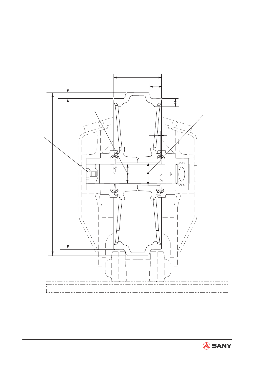
4.3.2  Idler

ZX215-1002010

3

5

4

6

9

7

8

1

2

157~255 Nm

Fig. 4-8 

4-17

Structure and Functions

SY365(B)H-9 Crawler Hydraulic Excavator

Unit: mm

No.

Check item

Criteria

Remedy

1

Protrusion outer dia.

Standard size

Repair limit

Build-up 

welding

or replace

635

2

Tread outer dia.

590

578

3

Tread thickness

30

24

4

Tread difference

22.5

26

5

Overall width

190

6

Tread width

44

7

Clearance between 
shaft and bushing

Standard 

size

Tolerance

Standard 

clearance

Clearance 

limit

Replace 

bushing

Shaft

Hole

φ

80

8

Interference be-
tween idler and 
bushing

Standard 

size

Tolerance

Standard 

interference

Interference 

limit

Shaft

Hole

φ

86

9

Clearance between 
bushing and support 
(Sum of clearances 
at both sides)

Standard clearance

Clearance limit

0.5-1.0

4-18

Structure and Functions

SY365(B)H-9 Crawler Hydraulic Excavator

ZX215-1002011

1

2

4

3

5

8

7

6

4.3.3 Carrier roller

Unit: mm

No.

Check item

Criteria

Remedy

1

Flange outer dia.

Standard size

Repair limit

Replace

190

2

Tread outer dia.

150

136

3

Tread width

57

4

Tread thickness

39

32

5

Flange width

16

6

Clearance be-
tween shaft and 
bushing

Standard 

size

Tolerance

Standard 

clearance

Clearance 

limit

Shaft

Hole

65

7

Interference be-
tween carrier roller 
and bushing

Standard 

size

Tolerance

Standard 

interference

Interference 

limit

Shaft

Hole

72

8

Carrier roller axial 
clearance 

Standard clearance

Clearance limit

0.44-0.76

Fig. 4-9 

4-19

Structure and Functions

SY365(B)H-9 Crawler Hydraulic Excavator

ZX215-1002012

549±59 Nm

4

5

7

9

10

3

6

8

2

1

4.3.4  Track roller

Unit: mm

No.

Check item

Criteria

Remedy

1

Flange outer dia.

Standard clearance

Repair limit

Build-up 

welding or 

replace

216

2

Tread outer dia.

180

168

3

Tread thickness

51.5

40.5

4

Overall width

250

5

Tread width

50.5

6

Flange width

27

7

Inner width

95

8

Clearance between
shaft and bushing

Standard 

size

Tolerance

Standard 

clearance

Clearance

limit

Replace 

bushing

Shaft

Hole

70

9

Interference between 
track roller and bush-
ing

Standard 

size

Tolerance

Standard 

interference

Interference 

limit

Shaft

Hole

77

10

Clearance between 
bushing and collar 
(Sum of clearances 
on both sides)

Standard clearance

Clearance limit

Replace

0.5 - 1.0

Fig. 4-10 

4-20

Structure and Functions

SY365(B)H-9 Crawler Hydraulic Excavator

4.3.5  Track 

ZX215-1002013

1

20

8

22

21

23

24

16

4

11

10

7

5

6

9

15

2

12

14

13

25

3

19

17

18

Fig. 4-11 

4-21

Structure and Functions

SY365(B)H-9 Crawler Hydraulic Excavator

Unit: mm

No.

Check item

Criteria

Remedy

1

Link pitch

Standard size

Repair limit

Reverse or replace

216

219

2

 Bushing outer diameter

Standard size

Reverse

66.9

60.23

3

Bushing metal thickness

11.1

Repair or replace

4

Link height

Standard size

Repair limit

116

104.4

5

Link metal thickness (bushing press-

fi

 tting portion)

30.65

22.5

6

Shoe bolt pitch

178.4

Adjust or replace

7

140.4

8

76.2

9

Link 

Inside width

102

10

Overall width

23.2

11

Tread width

21.3

12

Pin protrusion

4.2

13

Bushing protrusion

5.3

14

Overall length 
of pin

242

15

Overall length 
of bushing

158.9

16

Spacer thickness

17

Press-

fi

 tting 

force

Bushing

88.2 -245 kN{9-25 ton}

18

Regular pin

127.4 -274.4 kN{13-28 ton}

19

Master pin

78.4 -147 kN{8-15 ton}

4-22

Structure and Functions

SY365(B)H-9 Crawler Hydraulic Excavator

Unit: mm

No.

Check item

Criteria

Remedy

20

Shoe bolt

a. Regular 

link

Tightening torque(Nm{kgm})

Retightening angle (deg)

Retighten

Tri-grouser 

track shoe

1100

±

55

{112.2

±

5.6}

120

±

10

b. Master 

link

Tightening 

torque

(Nm)

Retightening angle (deg)

Lower torque 

limit

(Nm{kgm})

21

Interference between 
bushing and link

Standard size

Tolerance

Standard inter-

ference

Adjust or 

replace

Shaft

Hole

66.5

+0.46

+0.41

+0.074

0

0.36-0.464

22

Interference between pin 
and link

44.6

+0.19

+0.09

–0.188

–0.20

0.285-0.485

23

Clearance between pin 
and bushing

Standard size

Tolerance

Standard clear-

ance

Shaft

Hole

44.6

+0.19

+0.09

+1.35

+0.85

0.18-0.83

4-23

Structure and Functions

SY365(B)H-9 Crawler Hydraulic Excavator

Unit: mm

No.

Check item

Criteria

Remedy

1

Height

Standard size

Repair limit

Build-up welding 

or replace

30

20

2

Thickness

11

3

Length of base

29

4

24

5

Length at tip

 22

6

16

7

22

8

Thickness

Standard size

Repair limit

41

31

4.3.6  Tri-grouser track shoe

ZX215-1002014

1

2

3

4

5

6

7

8

Fig. 4-12 

4-24

Structure and Functions

SY365(B)H-9 Crawler Hydraulic Excavator

4.4  Hydraulic System, Part 1

4.4.1  Deployment of hydraulic parts

(1) Bucket cylinder
(2) Arm cylinder
(3) Boom cylinder
(4) Hydraulic tank
(5) Hydraulic oil 

fi

 lter

(6)  Main control valve
(7) Main pump
(8) Radiator
(9) Accumulator
(10)  Left travel motor
(11)  Right travel motor
(12) Swing motor
(13)  Hydraulic lockout control
(14)  Left pilot valve
(15)  Central swivel joint
(16)  Right pilot valve
(17)  Travel pilot valve
(18) Solenoid valve AS

18A. Hi/Lo travel speed shift solenoid valve

18B. Negative flow solenoid valve (front 

pump)

18C. Negative flow solenoid valve (rear 

pump)

18D. Pilot lockout solenoid valve

ZX335-1002007

1

2

Fig. 4-13 

4-25

Structure and Functions

SY365(B)H-9 Crawler Hydraulic Excavator

W365-1304008

3

4

5

6

7

A

8

17

9

10

11

12

13

14

15

16

18

18A

18E

18F

18B

18C

18D

A

Fig. 4-14 

4-26

Structure and Functions

SY365(B)H-9 Crawler Hydraulic Excavator

4.4.2  Hydraulic tank and 

fi

 lter

W365-1304009

B-B

B

B

1

2

6

7

3

4

5

6<++&

Fig. 4-15 

4-27

Structure and Functions

SY365(B)H-9 Crawler Hydraulic Excavator

(1) Hydraulic tank
(2) Level gauge
(3)  Filter element (oil drain)
(4) Filler cap
(5) Breather valve
(6)  Filter element (oil suction)
(7)  Filter element (oil return)

Speci

fi

 cation

Tank capacity: 340 L

Breather valve

Filter 

fi

 neness: 10

μ

m

Ambient temp: -30

℃ -

100

Pressure setting:  Air inlet side 

 0.005 MPa

                             Air outlet side 

 0.05 MPa  

4-28

Structure and Functions

SY365(B)H-9 Crawler Hydraulic Excavator

4.4.3 Hydraulic pump

Type: K5V160DTH1

×

4R-9T06-V

ZX335-1002010

B3

5

4

1

2

Psv1

Psv2

PH1

PH2

A2

A1

B1

a5(16N·m)

a1(36N·m)

a2(36N·m)

a4(36N·m)

a3(36N·m)

A3

Dr1(170N·m)

Dr2(170N·m)

Dr4(170N·m)

Dr4(170N·m)

3

Fig. 4-16 

4-29

Structure and Functions

SY365(B)H-9 Crawler Hydraulic Excavator

a1: Main pressure detection port (front pump)

a2: Main pressure detection port (rear pump)

a3: Regulator pressure detection port (front 

pump)

a4: Regulator control pressure detection port 

(rear pump)

a5: Delivery pressure detection port (pilot gear 

pump)

PH1: Pressure sensor mounting port (front 

pump)

PH2: Pressure sensor mounting port (rear 

pump)

A1: Oil delivery port (front pump)

A2: Oil delivery port (rear pump)

A3: Oil delivery port (pilot gear pump)

Psv1: Regulator control port (front pump)

Psv2: Regulator control port (rear pump)

Dr1: Drain plug (front pump)

Dr2: Drain plug (rear pump)

Dr4: Oil drain port

B1: Oil suction port (pump)

B3: Oil suction port (pilot gear pump)

(1)  1: Front pump

(2)  2: Rear pump

(3)  3: Pilot gear pump

(4)  4: Regulator (front pump)

(5)  5: Regulator (rear pump)

4.4.3.1 Outline


This pump consists of 2 variable swash 
plate plunger pumps, 2 adjustors, and 1 pi-
lot gear pump.

4-30

Structure and Functions

SY365(B)H-9 Crawler Hydraulic Excavator

ZX215-1002019

3

5

4

1

2

13

6

7

14

9

16

10

15

8

12

11

(1) Front shaft
(2)   Min. delivery adjusting screw
(3) Front casing
(4) Swash plate
(5) Slipper
(6) Plunger
(7) Cylinder block
(8) Oil distributor

(9) End cap
(10) Rear shaft
(11) Rear casing
(12) Gear pump
(13) Piston
(14)  Max. delivery adjusting screw
(15)  Gear pump shaft
(16) Driving pin

Fig. 4-17 

4-31

Structure and Functions

SY365(B)H-9 Crawler Hydraulic Excavator

ZX215-1002020

18

1

5

A

4

18

17

6

B

13

7

8

4.4.3.2 Function

The torque of the engine is transmitted
to the pump shaft (1), and drives cylinder
block (7) to rotate. At the same time, nine
plungers (6) slide along the oil distributor
(8). Plunger (6) moves back and forth in-
side cylinder block (7) and pressurized oil
is sucked in and discharged alternatively.

It is possible to change the displacement
by changing the swash plate angle.

4.4.3.3 Structure

Cylinder block (7) is supported to shaft (1)
by spline (17).

Shaft (1) is supported by front and rear
bearings (18).

Tip of plunger (6) is shaped as a concave
ball and slipper (5) is caulked to it to form
one unit.

Plunger (6) and slipper (5) constitute the
spherical bearing.

Swash plate (4) has flat surface (A), and
slipper (5) is always pressed against this
surface while sliding in a circular move-
ment.

Swash plate (4) conducts high pressure oil
to cylinder surface (B), and forms a static
pressure bearing when it slides.

Plunger (6) carries out relative movement
in the axial direction inside each cylinder
chamber of cylinder block (7).

Cylinder block (7) seals the pressurized oil
to oil distributor (8) and carries out relative
rotation.

This surface is designed so that the oil
pressure balance is maintained at a suit-
able level.

The oil inside the respective cylinder cham-
bers of cylinder block (7) is sucked in and
delivered through oil distributor (8).

Fig. 4-18 


Content      ..     5      6      7      8     ..