SANY Crawler Hydraulic Excavator SY365H-9, SY365BH-9. Shop Manual (2014) - page 10
 

  Index      Manuals     SANY Crawler Hydraulic Excavator SY365H-9, SY365BH-9. Shop Manual (2014)


Search            copyright infringement  


Content      ..     8      9      10      11     ..


SANY Crawler Hydraulic Excavator SY365H-9, SY365BH-9. Shop Manual (2014) - page 10


4-64

Structure and Functions

SY365(B)H-9 Crawler Hydraulic Excavator


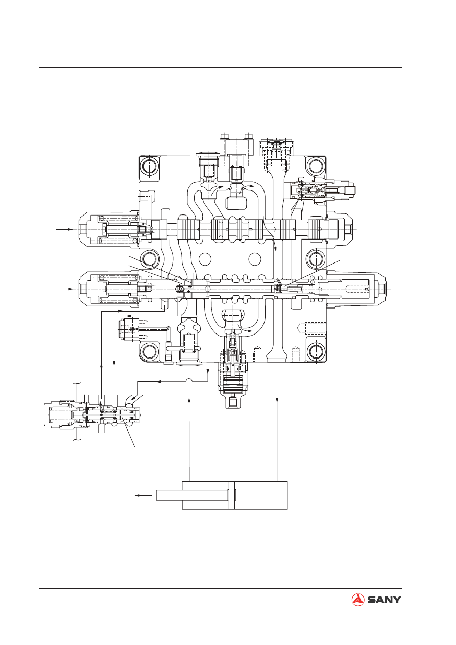
When pressure in arm cylinder head end (H) rises

XBa2

Dr1

XBa1

LCAT2

(Ba2)

BaR

XAa2

XAa1

Ba1

LCa

Pna1

Aa

Dra

R

H

(302-317)

(a)
(c)

(257-103)

WJV3651309

Fig. 4-54 

4-65

Structure and Functions

SY365(B)H-9 Crawler Hydraulic Excavator

4) Boom

Boom-up operation

(Pilot circuit)

When switched to the boom 1 spool (307), the side passage is closed and the pressure in port
Px (work equipment signal port) rises.

(Main circuit)

When boom-up operation is performed, the pilot oil is fed to port XAb1 and boom 1 spool
(303) moves to the left as shown in Fig. 4-55. The working oil from port P1 is introduced to the
neutral bypass (2) via the main passage (1). The neutral bypass is cut off by switching boom
1 spool (303). In this way, the working oil in the parallel passage pushes open the cone valve
(511) of the check valve, and 

fl

 ows to the boom 1 spool (303) via the U passage. It then 

fl

 ows

to the periphery of boom 1 spool (303) and is delivered to the boom cylinder head end (H) via
port Ab.

At the same time, the pilot oil is also fed to port XAb2 and boom 2 spool (307) moves to the
left as shown in Fig. 4-55. The working oil from P2 

fl

 ows the parallel passage. As the switch-

ing boom 2 spool (307) cuts off the neutral bypass, the working in the parallel passage 

fl

 ows

into boom 2 spool (307) via the U passage. The oil then pushes open the cone valve (511) of
the check valve, comes into con

fl

 uence with the oil from port Ab, and is fed to the boom cylin-

der head end (H). (This is called the boom con

fl

 uence function.)

On the other hand, the oil 

fl

 ows to the periphery of boom 1 spool (303) via port Bb from oil re-

turn side of the boom cylinder rod end (R) and goes back to the working oil tank via the ports
R1 and R3.

4-66

Structure and Functions

SY365(B)H-9 Crawler Hydraulic Excavator

XBb1

XBb2

511

513

Bb

BaR

XAb1

XAb2

R

H

AbR

Ab

LCb

Dr2

511

511

WJV3651310

Fig. 4-55 

4-67

Structure and Functions

SY365(B)H-9 Crawler Hydraulic Excavator

Boom-down operation

(Pilot circuit)


When switched to the boom 1 spool (303), the side passage is closed and the pressure in port 
Px (work equipment signal port) rises. Pressurized oil is fed to the port PbL at the same time. 
Relief signal is sent to the lock valve selector GP (252).

(Main circuit)


When boom-down operation is performed, the pilot oil is fed to port XBb1 and boom 1 spool 
(303) moves to the right as shown in Fig. 4-56. The working oil from port P1 is introduced to 
the neutral bypass (2) via the main passage (1). The neutral bypass is cut off by switching 
boom 1 spool (303). In this way, the working oil in the parallel passage pushes open the cone 
valve (511) of the check valve, and 

fl

 ows to the boom 1 spool (303) via the U passage. It then 

fl

 ows to the periphery of boom 1 spool (303) and is delivered to the boom cylinder rod end (R) 

via port Bb.


On the other hand, the oil returning from the head end (H) of boom cylinder 

fl

 ows to the hole (a) 

and periphery of boom 1 spool (303).


The pressure of return oil rises due to the dead weight of boom. To maintain suf

fi

 cient pres-

sure, with the help of the oil passage inside the spool, the cone valve (303-317) in spool is 
pushed to the right, as shown in Fig. 4-56, and the oil 

fl

 ows out of the spool. As the working oil 

for boom-down operation, the pressurized oil is again delivered to the boom cylinder rod end 
(R) (which is called boom regeneration function). The return oil entering the internal passage 
of spool via the hole (a) partially goes back to the oil tank via the hole (b).

XBb1

511

513

Bb

BbR

XAb1

R

H

Ab

LCb

(b)

(a)

(303-317)

WJV3651311

Fig. 4-56 

4-68

Structure and Functions

SY365(B)H-9 Crawler Hydraulic Excavator

5) Bucket

Bucket-dig operation

(Pilot circuit)

When switched to the bucket spool (304), the side passage is closed and the pressure in port
Px (work equipment signal port) rises. The pressure oil is fed to port XBp2 at the same time.

(Main circuit)

When bucket-dig operation is performed, the pilot oil is fed to the port XBc and the bucket
spool (304) moves to the left as shown in Fig. 4-57. The working oil from port P1 is guided
to the neutral bypass (2) via main passage (1). As the neutral bypass is cut off by switching
bucket spool (304), the working oil in the parallel passage pushes open the cone valve (511)
of the check valve, and 

fl

 ows to the bucket spool (304) via the U passage. It then 

fl

 ows to the

periphery of bucket spool (304) and is fed to the bucket cylinder head end (H) via port Bc.

On the other hand, return oil from the bucket cylinder rod end (R) 

fl

 ows in via port Ac. It then

goes back to the oil tank via the ports R1 and R3 from the periphery of spool.

When boom-up and bucket-dig operations are performed at the same time, the pilot oil is led
to the port PAcs. Therefore, the travel of bucket spool is not restricted to the end, but can be
held in a position on the way. As a result, bucket cylinder passage is throttled and working oil

fl

 ows to boom 1 spool (303) via bucket spool (304). In this way, boom-up operation have the

priority.

Bc

BcR

XBc

R

H

AC

LCk

511

AcR

XAc

PAcs

Confluence

WJV3651312

Fig. 4-57 

4-69

Structure and Functions

SY365(B)H-9 Crawler Hydraulic Excavator

Bucket-dump operation

(Pilot circuit)


When switched to the bucket spool (304), the side passage is closed and the pressure in port 
Px (work equipment signal port) rises. The pilot oil is also fed to the port XBp2 at the same 
time.

(Main circuit)


When bucket-dump operation is performed, the pilot oil is fed to the port XAc and bucket 
spool (304) moves to the right as shown in Fig. 4-58. The working oil from port P1 is led to the 
neutral bypass (2) via the main passage (1). The neutral bypass is cut off by switching bucket 
spool (304). Therefore, the working oil in the parallel passage pushes open the cone valve (511) 
of the check valve and 

fl

 ows to the bucket spool (304) via the U passage. It then 

fl

 ows to the 

periphery of bucket spool (304) and is fed to the bucket cylinder rod end (R) via the port Ac.


On the other hand, return oil from the bucket cylinder head end (H) enters via the port Bc, 
passes the spool periphery of spool, and goes back to working oil tank via the ports R1 and 
R2.

Bc

BcR

XBc

R

H

Ac

LCk

511

AcR

XAc

PAcs

Confluence

WJV3651313

Bucket con

fl

 uence


When bucket-dig or -dump operation is performed, the pilot oil is fed to the port XBp2 and the 
neutral bypass stop valve spool (310) is switched. Working oil from port P2 is led to the neu-
tral bypass (4) via the main passage (3). The neutral bypass is cut off by switching neutral by-
pass valve spool (310). Therefore, working oil pushes open the check valve (515) and comes 
into con

fl

 uence with bucket spool (304) via the internal passage and the U passage.

Fig. 4-58 

4-70

Structure and Functions

SY365(B)H-9 Crawler Hydraulic Excavator

6) Swing

When swing operation performed separately

(Pilot circuit)


When switched to the swing spool (305), the side passage is closed and the pressure in the 
port Px (work equipment signal port) rises.

(Main circuit)


When swing is operated separately, the pilot oil is fed to the port XAs (or XBs) and swing 
spool (305) is switched. Working oil from port P2 is led to the neutral bypass (4) via the main 
passage (3). Neutral bypass is cut off by switching swing spool (305). Therefore, working oil 
in the parallel passage pushes open the logic cone valve (254-101) of the swing logic com-
ponent and 

fl

 ows to the swing spool (305) via the U passage. It then 

fl

 ows to the periphery of 

swing spool (305) and is delivered to the swing motor via port As (or Bs).


On the other hand, return oil from the swing motor 

fl

 ows in via port Bs (or port As). Then, it 

fl

 ows into tank ports R1 and R2 from the periphery of spool and goes back to the working oil 

tank.

XAs

Bs

XBs

As

LCs

Pns

(254-101)

Swing motor

WJV3651314

Fig. 4-59 

4-71

Structure and Functions

SY365(B)H-9 Crawler Hydraulic Excavator

7) Priority function

This function enables the working oil from port P to be suf

fi

 ciently allocated to the work equip-

ment under higher load in order to improve the operability when the arm-in operation is per-
formed along with swinging operation.

The following shows the priority of swinging operation relative to the arm-in operation.

(Main circuit)

When pressure oil is applied to the port Pna1 of the logic control valve (255), the piston (255-
356) and spool (253-107) move upward. The lifting distance of cone valve (253-101) is lim-
ited.

In this way, the passage from the parallel passage to the U passage is throttle. As a result, oil
from the arm 1 spool has the priority to go to the swing spool, giving the priority to the boom-
up operation.

Aa

XAa1

XBa1

LCa

Ba1

(253-101)

(253-107)

(255)

(255-356

Pna1

WJV3651315

Fig. 4-60 

4-72

Structure and Functions

SY365(B)H-9 Crawler Hydraulic Excavator

8) Backup

The backup spool is used to control attachment such as hydraulic shear.

Backup operation

(Pilot circuit)


When switched to the backup spool (309), the side passage is closed and the pressure in port 
Px (work equipment signal port) rises.

(Main circuit)


When the backup is operated, the pilot oil is fed to the port XAo (or XBo) and the backup 
spool (309) is switched. Working oil from port P2 is fed to the neutral bypass (4) via the main 
passage (3). Neutral bypass is cut off by switching backup spool (309). Therefore, working oil 
in the parallel passage pushes open the cone valve (511) of the check valve and 

fl

 ows to the 

backup spool (309) via the U passage. Then, it 

fl

 ows into the periphery of backup spool (309) 

and is supplied into the attachment via port Ao (or Bo).


On the other hand, return oil from the attachment 

fl

 ows in via port Bo (or port Ao). Then, it 

fl

 ows into tank ports R1 and R2 from the spool periphery and returns to the working oil tank.

XAo

511

Bo

BoR

R

H

Ao

LCo

XBo

Confluence

WJV3651316

Fig. 4-61 

Backup con

fl

 uence

To achieve backup con

fl

 uence, pilot oil is also fed to port XBp1 and the bypass stop valve spool 

(310) is switched. Working oil from port P1 is introduced into neutral bypass (2) via main passage 
(1). Neutral bypass is cut off by switching bypass valve spool (310). Therefore, working oil push-
es open the cone valve (515) of check valve and comes into con

fl

 uence with backup spool (309) 

via the internal passage and the U passage.

4-73

Structure and Functions

SY365(B)H-9 Crawler Hydraulic Excavator

9) Straight travel

When travel spool (301) is operated along with other spools at the same time. 

The following case shows when travel spool (301) and swing spool (305) are operated at the 
same time. 

(When pilot oil is delivered to the ports XAtL, XAtr and Xas)

(Pilot circuit)


Close the side passage of right/left travel spool (301) and the downstream side passage of 
swing spool (305). Pilot oil from port PG is fed to port PTa in order to switch the straight travel 
spool (308).

(Main circuit)


When straight travel spool (308) is switched, the port P2 and the right/left travel spool (301) 
are interconnected through for priority. The port 1 and the parallel passage of swing - boom 
2 - backup - arm 1 oil circuit / boom 1 - bucket/ - arm 2 circuit are interconnected through for 
priority. Therefore, the working oil from port P2 is mainly delivered to the ports Atl and Atr and 
distributed evenly to the two travel motors.


On the other hand, the working oil from port P1 is delivered to the swing motor via port As.


When oil pressure in the port P2 is lower than that in the port P1, the working oil form port P1 
will be partially delivered to the port P2. In this way, sudden drop of travel speed can be pre-
vented.

XBtL

(PTb)

(PTa)

XAtL

P1

R3

P2

WJV3651317

Fig. 4-62 

4-74

Structure and Functions

SY365(B)H-9 Crawler Hydraulic Excavator

10) Function of lockout valve

The lockout valve selector module (252) is mounted between the arm cylinder rod end (R) and 
the arm 2 spool (302) and arm 2 spool (306). It is used to reduce the internal leakage of the spool 
due to cylinder pressure.

Likewise, lockout valve selector module (252) is also mounted between the boom cylinder head 
end (H) and the arm 1 spool (303) and boom 2 spool (307) to reduce the internal leakage of he 
spool due to cylinder pressure.

The 

fi

 gure below shows the case of boom cylinder head end (H). (Similar case applies to the arm 

cylinder rod end (R).)

Spool in neutral position

When boom 1 spool (303) and boom 2 spool (307) are in a neutral position, the spool (252-511)
inside the lockout valve selector module is pressed against the seat of the body (252-101) of
the lockout valve selector module, as shown in Fig. 4-63, by the preload of spring (252-512).

In this position, working oil in the boom cylinder head end (H) 

fl

 ows in via hole (a) and 

fl

 ows

out from hole (b) through the periphery of the lockout valve selector module spool (252-511),
pressing the cone valve (513) against the seat of the valve block via hole (b). By this means,
oil leakage is reduced.

(252-512)

(252-101)

Drb

(252-511)

(b)

(a)

513

Ab

LCb

Bb

(RH)

XBb1

XAb1

BbR

PbL

WJV3651318

Fig. 4-63 

4-75

Structure and Functions

SY365(B)H-9 Crawler Hydraulic Excavator

Boom-down operation

In boom-down operation the pilot oil is fed to the ports PbL, XBb1 and XBb2. Spool (252-511) in-
side the lockout valve selector module is pushed to the top by the pilot oil as shown in Fig. 4-64. 
Due to the movement of spool (252-511) inside the lockout valve selector module, hole (a) is cut 
off and working oil from boom cylinder head end (H) does not go to spring chamber (RH). In addi-
tion, oil in the spring chamber (RH) enters the oil leak circuit via the hole (b). In this way, the cone 
valve (513) is pushed open by the pressure in boom cylinder head end (H) and the function of the 
lockout valve selector module (252) is deactivated.

(252-512)

(252-101)

Drb

(252-511)

(b)

(a)

513

Ab

LCb

Bb

(RH)

XBb1

XAb1

BbR

511

PbL

WJV3651319

Fig. 4-64 

Boom-up operation

In boom-up operation the pilot oil is fed to the ports XAb1 and XAb2. The cone valve (513) is 
pushed open by the oil from boom 1 spool (303) and boom 2 spool (307). The working oil goes to 
the port Ab as a result.

4-76

Structure and Functions

SY365(B)H-9 Crawler Hydraulic Excavator

11) Function of main relief valve

The main relief valve is mounted on the valve block A (101). It has the following functions:


Working oil ful

fi

 ls the cavity (a) through the hole in valve post housing (601-101) and valve 

post (601-511). The valve post (601-511) is therefore pressed against the housing (601-101). 
Reliable sealing has formed as a result.


When pressure in passage (P) exceeds the preload of spring (601-521), the cone valve (611) 
opens. Therefore, the working oil passes through the gap between the housing (601-101) and 
valve pocket (601-102) from the periphery of cone valve (601-401) and goes to the low pres-
sure passage (R).


Opening of cone valve (601-401) causes pressure drop in cavity (a). So the valve post (601-
511) is opened. In this way, working oil in passage (P) 

fl

 ows to the low pressure passage (R) 

directly.


When pressure oil higher than 3MPa is fed to the port Pz, it pushes plunger (601-302) to the 
left. The preload of spring (601-512) increases as a result and pressure boosts at the mo-
ment.

(601-101)

(601-401)

(601-511)

(601-302)

(a)

(601-512)

(601-102)

Pz

R

P

WJV3651320

Fig. 4-65 

4-77

Structure and Functions

SY365(B)H-9 Crawler Hydraulic Excavator

12) Function of port relief valve

The port relief valve, mounted between the oil tank port and low pressure passage, can prevent 
cavitation as an oil compensation check valve except working as a port relief valve. Functions of 
the valve are given below:

Functioning as a relief valve

Working oil ful

fi

 ls into cavity (B) via the hole (A) on plunger (301). Valve post (511) is pressed

against valve seat (541), and valve seat (541) is pressed onto the seat of the valve block,
forming a reliable sealing.

(A)

(B)

541

301

511

R

P

WJV3651321

(C)

611

621

P

R

WJV3651322

When pressure in passage (P) exceeds the preload of spring (621), cone valve (611) is
pushed open. Therefore, working oil 

fl

 ows through hole (C) via the periphery of cone valve (611)

and enters the low pressure passage (R).

Fig. 4-66 

Fig. 4-67 

4-78

Structure and Functions

SY365(B)H-9 Crawler Hydraulic Excavator


Opening of cone valve (611) causes pressure in cavity (B) to drop and valve post (511) is 
opened. In this way, working oil in passage (P) goes to the low pressure passage (R) directly.

P

R

(B)

511

611

WJV3651323

Fig. 4-68 

Functioning as oil complement check valve against cavitation

When negative pressure is formed in passage (P), working oil is fed from passage (R). When 
pressure in passage (R) exceeds the pressure in passage (P), valve seat (541) moves to the right 
direction. Therefore, working oil is delivered from passage (R) to passage (P) via the periphery of 
valve seat (541). Cavitation is prevented as a result.

P

R

541

WJV3651324

Fig. 4-69 

4-79

Structure and Functions

SY365(B)H-9 Crawler Hydraulic Excavator

ZX215-1002081

L

PB

PA

IP

M

DB

SH

PG

B

A

1

2

4.6  Hydraulic System, Part 3

4.6.1 Swing motor

Type: M5X180CHB-10A-3NA/265

Model

M5X180CHB-10A-3NA/265

Theoretical dis-

placement

180.1 cm

3

/rev

Safety valve 

press. setting

26.0 MPa 

Max swing speed

1470 rpm

Brake release 

pressure

2.7-4.9 MPa 

Speci

fi

 cations

A: Main oil port
B: Main oil port
M: Makeup port
PA: Pressure detection port
PB: Pressure detection port
DB: Lubricant port
PG: Brake release port
SH: Brake command port
L: Level stick
IP: Gear oil feed port
(1) Safety valve
(2) Anti-swing valve

Fig. 4-70 


Content      ..     8      9      10      11     ..