SANY Crawler Hydraulic Excavator SY365H-9, SY365BH-9. Shop Manual (2014) - page 17
 

  Index      Manuals     SANY Crawler Hydraulic Excavator SY365H-9, SY365BH-9. Shop Manual (2014)


Search            copyright infringement  


Content      ..     15      16      17      18     ..


SANY Crawler Hydraulic Excavator SY365H-9, SY365BH-9. Shop Manual (2014) - page 17


4-178

Structure and Functions

SY365(B)H-9 Crawler Hydraulic Excavator

ZX215-1002197

MAX

Arm OUT PPC pressure

Bucket CURL PPC pressure

Bucket DUMP PPC pressure

L. Travel PPC pressure

Swing PPC pressure

Arm IN PPC pressure

Boom RAISE PPC pressure

Pump 1
delivery
amount

Pump 1
delivery
amount

Pump 1
delivery
amount

Pump 1
delivery
amount

Pump 1
delivery
amount

Pump 1
delivery
amount

Pump 1
delivery
amount

Corresponding
delivery output

Fig. 4-185 

4-179

Structure and Functions

SY365(B)H-9 Crawler Hydraulic Excavator

ZX215-1002198

Pump 2
delivery
amount

Pump 2
delivery
amount

Pump 2
delivery
amount

Pump 2
delivery
amount

Pump 2
delivery
amount

Pump 2
delivery
amount

Pump 2
delivery
amount

Boom RAISE PPC pressure

Arm IN PPC pressure

Arm OUT PPC pressure

Bucket CURL PPC pressure

Bucket DUMP PPC pressure

Boom LOWER PPC pressure

R. Travel PPC pressure

MAX

Corresponding
delivery output

Fig. 4-186 

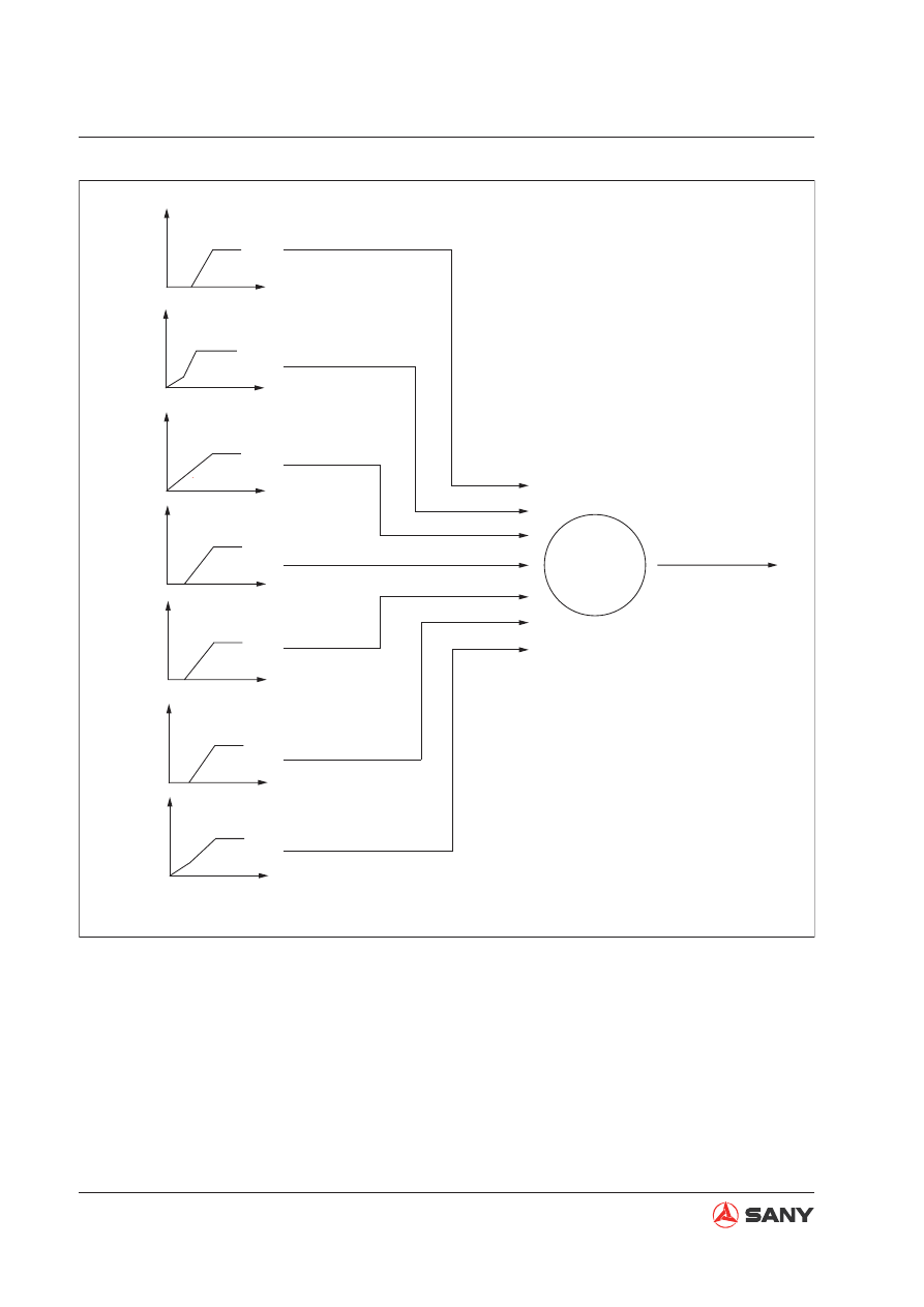
Function

Use the work equipment and swing pilot pres-
sure signal directly as the hydraulic pump dis-
charge control signal. Pilot pressure is applied 
on the valve stem and, on the other hand, 
is collected by the controller. The controller 
keeps the discharge amount of the hydraulic 
pump at the speci

fi

 ed value of the correspond-

ing pilot pressure according to the functional 
relation between the set hydraulic pump dis-

charge amount and pilot pressure. During 
combined operation, the set discharge amount 
of each operation shall be added. 

Operation 

When the work equipment is operating, the 
controller collects the signal of pilot pressure 
sensor, and determines the control discharge 
amount of pump 1 and pump 2 according to 
the pressure signal.

4-180

Structure and Functions

SY365(B)H-9 Crawler Hydraulic Excavator

Function

Operation


It is mainly used to calculate the theoreti-
cal maximum displacement. The system 
employs constant power control. Two 
regulators are interconnected hydraulically, 
enabling synchronized operation of two 
actuators of the same specification at the 
same time. Change of pump 

fl

 ow is deter-

mined by the sum P


of working pressures 

of both hydraulic pumps. So long as it sat-
is

fi

 es


2P

0

P

2 P

Max, 

the sum of powers 

of both hydraulic pumps remains constant, 
exceeding not the power of diesel engine. 


When work equipment is working, the con-
troller collects throttle position signal and 
gives a constant current in order to control 
power of pump. 

4.10.4.1  Constant power control

ZX215-1002199

Pressure

Flow

P

Max

P

Max

P

P

0

Pump curve P-Q

Q

Function

Operation

4.10.4.2 ESS control


Changing of the engine speed due to load change controls the pump power, and engine out-
put can be used more ef

fi

 ciently. (This function can also prevent the engine from losing con-

trol when the machine is operating under harsh conditions (eg. high - altitude area).

The engine control panel controls the target operating speed of the engine. 


The engine controller collects the actual speed signal from the speed sensor, and preform a 
loop control with the target operating speed. Then, the controller involves the output of loop 
control with the calculation of the solenoid valve control signal, and sends the 

fi

 nal regulating 

current signal to the pump proportional solenoid valve. 


The solenoid valve controls pump 

fl

 ow by feeding pilot oil to the pump regulator according to 

the signal sent from the controller. 

Fig. 4-187 

4-181

Structure and Functions

SY365(B)H-9 Crawler Hydraulic Excavator

4.10.5  Valve control function

W365413086

M

P


R

F

Hi

Lo

A

B

F1

F2

F3

F4

F5

Esc

Enter

Engine

Pressure sensor

Pressure sensor

Swing priority

Bucket confluence

Main pump

Injection
pump

Governor
motor

Main control valve

Speed
sensor

Servo

Servo

Valve

Valve

Fuel control dial

CAN bus

(Motor drive signal)

(Throttle position feedback signal)

(Control signal)

(Control signal)

(Engine speed signal)

Swing signal

Bucket DUMP signal

Bucket DIG signal

Arm OUT signal

Arm IN signal

Boom DOWN signal

Boom UP signal

Left travel signal

Right travel signal

Controller

Fig. 4-188 

Bucket 

fl

  ow control

Swing priority control

4-182

Structure and Functions

SY365(B)H-9 Crawler Hydraulic Excavator

ZX215-1002201

Swash plate angle

Bucket joystick
pilot pressure

Max

Min

ZX305-1002202

Bucket confluence
valve current

450mA

400mA

Bucket joystick
pilot pressure

Fig. 4-189 

Fig. 4-190 

1) Bucket 

fl

 ow control

Function

Control the pump swash plate angle according 
to the operation of bucket control lever.

Operation

When the bucket control lever is operated, the 
controller collects the signal from the bucket 
DUMP pressure sensor and bucket CURL 
pressure sensor, and controls the bucket con-

fl

 uence proportional valve.

2) Swing priority control

Function


Pressurized oil from pump 1 bypasses bucket 1 valve spool, and 

fl

 ows 

fi

 rst to swing motor 

valve spool to activate swing 

fi

 rst.

Operation


When signals from pump 1 pressure sensor, arm pressure sensor and swing pressure sensor 
meet the following conditions, the controller activates the solenoid valve. The solenoid valve 
conducts pilot pressure oil to arm 

fl

 ow controller and limits the alternate circuit of arm 1 valve 

spool. Swing valve spool 

fi

 rst ensures swing motor power, preventing the counter acting force 

when the arm is retracting from affecting the positioning of the upper swing structure. 

Operating condition


Swing pressure sensor: signal output available

4-183

Structure and Functions

SY365(B)H-9 Crawler Hydraulic Excavator

4.10.6  Dual travel speed control

W365413085

M

P


R

F

Hi

Lo

A

B

F1

F2

F3

F4

F5

Esc

Enter

Travel Motor

Regulator

Regulator

Main Control Valve

Travel Speed
Solenoid Valve

Left travel pressure sensor

Right travel pressure sensor

Engine

Injection
Pump

Governor 
Motor

Main Pump

Servo

Servo

Fuel Control Dial

(Control signal)

(Control signal)

Controller

(CAN Bus)

(Throttle position 

feedback signal)

(Motor drive signal)

Fig. 4-191 

4-184

Structure and Functions

SY365(B)H-9 Crawler Hydraulic Excavator

Function

Travel mode control

Operation

When travel mode is set to LOW, the angle
travel motor swashplate reaches its maxi-
mum and travel speed is slow.

When the controller receives signal from
travel pressure sensor under the following
condition, it activates the solenoid valve.
The solenoid valve delivers pilot oil to the
travel motor swashplate angle control valve
in order to reduce the angle to its minimum
and increase travel speed.

Operating condition

Fast travel function on the monitor is on. 

Note: 

When lifting the track on one side with 

the help of work equipment and running the 
track, the pump control pressure on the side 
increases to enable fast running of the track. 
When the machine is traveling under HIGH 
mode, the travel mode cannot be changed 
even if work equipment is operated (work 
equipment pressure sensor is turned ON). 

4-185

Structure and Functions

SY365(B)H-9 Crawler Hydraulic Excavator

4.10.7  Engine preheat/overheat alarm

W365413087

M

P

F

Hi

Lo

A

B

F1

F2

F3

F4

F5

Esc

Enter

Heat

Start switch

Main Control Valve

Preheat Relay

Engine

Main Pump

Governor motor

Coolant Temp
Sensor

(CAN bus)

(Motor drive signal)

(Throttle position

 feedback signal)

Controller

Servo

Servo

(Control signal)

(Control signal)

Fig. 4-192 

4-186

Structure and Functions

SY365(B)H-9 Crawler Hydraulic Excavator

1) Engine preheating

Function

Preheat control

Operation

The excavator starts preheating when it is powered on.

Operating condition

Low temperature switch is closed; excavator is energized; auto preheating begins at starting.

2) Engine overheat alarm

Function

When coolant temperature is high (over 103

 ) during operation, the monitor displays alarm.

Operation

The controller collects signal from coolant temperature sensor. If coolant temperature is too
high, alarm message will be generated and sent to the monitor. Receiving the alarm message,
the monitor will illuminate the alarm indicator light.

Operating condition

Power on

Coolant temperature greater than 103

3) Alarm - low engine oil pressure

Function

The controller collects signal from engine oil pressure sensor. When engine speed is greater
than 600 rpm and engine oil pressure is too low, alarm message will be generated and sent to
the monitor. Receiving the alarm message, the alarm indicator lights up.

4-187

Structure and Functions

SY365(B)H-9 Crawler Hydraulic Excavator

4.10.8  Auto deceleration/acceleration control

Function


When all control levers are in the neutral 
position, lower engine speed in order to re-
duce fuel consumption and noise. 


When any control lever is operated, engine 
speed will be back to the setting of the fuel 
control dial. 

ZX225-1002022

A

B

F1

F2

F3

F4

F5

Esc

Enter

Engine

Engine
throttle 
controller

Fuel Control Dial

Right Joystick control

Boom

Bucket

Controller

CAN Bus

Control lever signal

Swing

Arm

Left
Joystick
Control

Left travel

Right travel

Travel
Control 
Levers

DOWN

UP

DIG

DUMP

IN

OUT

RIGHT

LEFT

FWD

BWD

FWD

BWD

(Throttle signal)

Fig. 4-193 

Fig. 4-194 

ZX335-1002061

0.2S

Drop 100 rpm

0.5S

(1400rpm)

0.5S

3.2S

Speed (rmp)

Set speed

Auto deceleration

Control lever

Time (s)

Operated

Unoperated

Operated

Operation


Engine speed will drop to the speed of gear position 1 (100 rpm lower than the set speed) 0.2 
second after the control levers are placed in the neutral position. The engine will run at low 
speed (1400 rpm) after another three (3) seconds. This can reduce void 

fl

 ow of hydraulic sys-

tem and wear of the engine, hence saving energy and reducing noise. When any control lever 
is operated to resume the operation, the engine speed will be restored. 


When any control lever is operated during engine deceleration, engine speed will increase im-
mediately to the speed set by the fuel control dial. 

4-188

Structure and Functions

SY365(B)H-9 Crawler Hydraulic Excavator

4.10.9  Engine speed calibration function

W365413088

M

P


R

F

Hi

Lo

A

B

F1

F2

F3

F4

F5

Esc

Enter

Speed
sensor

Main pump

(CAN bus)

Engine

Injection
pump

Governor 
motor

Main valve

Bucket confluence

Swing pripority

Pressure sensor

Controller

Servo

Servo

Pressure sensor

Engine speed signal

Control signal

Control signal

R. Travel signal

L. Travel signal

Boom UP signal

Boom DOWN signal

Arm IN signal

Arm OUT signal

Bucket DIG signal

Bucket DUMP signal

Swing signal

Fuel control dial

Fig. 4-195 

4-189

Structure and Functions

SY365(B)H-9 Crawler Hydraulic Excavator

Function

Enter the maximum engine speed for each 
working mode as a criteria for engine speed 
control.

Operation

1. Auto calibration of engine speed requires

starting the engine.

2. Call the interface of System Information

and select Throttle Installation Aid.

A.  Turn the fuel control dial to position 1.

B.  Press the key [F4] to start speed cali-

bration process.

C.  Turn the fuel control dial after calibra-

tion.

D.  Repeat step (2) to finish calibration of 

speed at all positions.

E.  Press the key [F5] or [ESC] to end 

calibration.

XP2051203013

n/min

AUTO

rpm

s

Throttle Help Info

Current Gear      N

Engine Speed rpm

Gear Position     V

Throttle Position V

Fig. 4-196 

4-190

Structure and Functions

SY365(B)H-9 Crawler Hydraulic Excavator

4.10.10  System parts and components

1) Pump pressure sensor

Operation

The illustration on the right shows the rela-
tionship between the pressure acting upon
the sensor and the output voltage.

ZX335-1002067

Ӵᛳ఼䕧ߎ⬉य़

(V)


⊍य़࡯

(MPa)

W365-1304208

A

A

B

C

B

C

Connector

Housing

Pressure joint

Connection Diagram

Terminal No.

Signal Name

Power (+5V)

Ground

Output

Fig. 4-197 

Fig. 4-198 

4-191

Structure and Functions

SY365(B)H-9 Crawler Hydraulic Excavator

Operation


The illustration on the right shows the rela-
tionship between the pressure acting upon 
the sensor and the output voltage. 

2) Pilot pressure sensor

W365-1304208

A

A

B

C

B

C

Connector

Housing

Pressure joint

Connection Diagram

Terminal No.

Signal Name

Power (+5V)

Ground

Output

ZX335-1002067

Ӵᛳ఼䕧ߎ⬉य़

(V)


⊍य़࡯

(MPa)

Fig. 4-199 

Fig. 4-200 

4-192

Structure and Functions

SY365(B)H-9 Crawler Hydraulic Excavator

3) Engine speed sensor

Function

Engine speed sensor is mounted on the gear ring of 

fl

 ywheel. It calculates the number of gear

teeth passing before the sensor and sends the result to the controller.

Note: 

If the engine speed sensor has not been tightened to the speci

fi

 c torque, it may fail to pro-

duce signal. Always tighten the engine speed sensor to the speci

fi

 c torque. 

ZX335-1002070

1

2

Fig. 4-201 

4) Engine oil pressure switch

W365413089

1

2

Fig. 4-202 

(1) Pressure detector

(2) Connector

Function

Engine oil pressure switch is mounted on the 
delivery pipe of engine oil 

fi

 lter. It detects en-

gine oil pressure and sends generated pres-
sure signal or alarm signal to the controller.

4-193

Structure and Functions

SY365(B)H-9 Crawler Hydraulic Excavator

5) Fuel level sensor

ZX215-1002246

1

2

3

4

Fig. 4-203 

(1) Float

(2) Lever

(3) Shell

(4) Connector

Function

Signal from the sensor will be collected by the controller and displayed on the monitor. Resis-
tance output sensors like hydraulic oil temperature sensor, fuel level sensor and coolant tempera-
ture sensor send signal to the controller. The controller collects, process and calculate voltage 
signals and converts it into related information that will be displayed on the monitor.

Speci

fi

 cations

Electrical parameters:

Total resistance: 100

Ω

Tolerance: 

±

5%

Upper limit: Ru

9.6

Ω

Lower limit: Rd

86

Ω

Variation: Nonlinear

Max. input volt: 12VDC

Mechanical parameters:

Rotor angle: 105

°

Vertical distance between upper and lower limits of the 

fl

 oat (measurable range of 

fl

 uid level):

500 mm


Content      ..     15      16      17      18     ..