SANY Crawler Hydraulic Excavator SY215CLC (CUMMINS QSB6.7 engine). Shop Manual - page 15
 

  Index      Manuals     SANY Crawler Hydraulic Excavator SY215CLC (CUMMINS QSB6.7 engine). Shop Manual


Search            copyright infringement  


Content      ..     13      14      15      16     ..


SANY Crawler Hydraulic Excavator SY215CLC (CUMMINS QSB6.7 engine). Shop Manual - page 15


Structure and Function

SY215C

LC

4-140

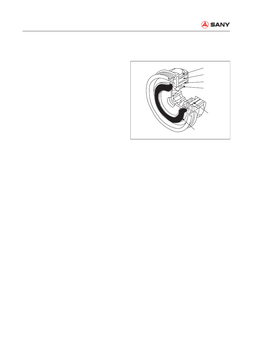
4.7.6 Clutch


The electromagnetic clutch is used to 
transmit moment of torsion. When the en-
gine is operating, the compressor  may not 
be working. The clutch controls the opera-
tion of the compressor only when the air 
conditioner is under refrigerating mode.


Operating principle

When the A/C switch is turned on, the 
clutch coil with an electromagnet gener-
ates a magnetic 

fi

 eld and attracts the metal 

piece. The stator and rotor of the clutch are 
engaged and drives the main shaft of the 
compressor into rotation. 

1- Rotor
2- Stator coil
3- Snap ring
4- Ball bearing
5- Stator
6- Center piece

ZX215-1002145

1

2

3
4

5

6

Structure and Function

SY215C

LC

4-141

4.7.7 Condenser

1- Condenser core
2- Bracket
3-  Bolt with gasket
4- Refrigerant inlet
5- Refrigerant outlet

Function


The condenser changes high-temperature, 
high-pressure gas refrigerant (16Kg/cm², 
approx. 80°C) to high-temperature and 
high-pressure liquid refrigerant (16Kg/cm², 
below approx. 60°C) through radiating. 

ZX215-1002146

1

2

3

5

4

Structure and Function

SY215C

LC

4-142

4.7.8 Expansion valve

1- Spring
2- Diaphragm
3- Probe
4- Needle valve

Operating principle


Refrigerant from the reservoir spurts out 
via the ori

fi

 ce, turns into low-temperature, 

low-pressure liquid (mist) after expanding, 
and enters the evaporator. 

4.7.9 Evaporator

1- Expansion valve
2- Evaporator

Operating principle


The evaporator is a kind of heat exchanger 
that looks like a condenser. Hot air in the 
cab is conducted into the evaporator via 
the blower motor and undergoes heat ex-
change with the surface of the evaporator. 
Heat is absorbed and hot air turns into 
cold air, which flows into the cab through 
the air ducts.  Evaporator surface absorbs 
heat

Refrigerant in the evaporator ab-

sorbs heat 

 Refrigerant evaporates . 

Evaporated refrigerant (gas) is absorbed 
by the compressor.

ZX215-1002148

1

2

ZX215-1002147

1

2

3

4

Evaporator

Reservoir

Compressor

Structure and Function

SY215C

LC

4-143

4.7.10 Dehydrator

1- Inlet
2- Outlet
3- Receiver/dehydrator
4- Desiccant

Function


Temporary storage of refrigerant


Dehydration of refrigerant


Dust removal from refrigerant


Measure the volume of refrigerant

ZX215-1002149

1

2

3

4

Structure and Function

SY215C

LC

4-144

4.7.11 Pressure switch

1- O-ring
2-  Mobile contact point
3- Hood
4- Plug and 

fi

 xed contact

5- Spring
6- Chamber
7- Diaphragm

Function


The pressure switch is installed between 
the reservoir and the expansion valve (hi-
pressure pipe). It is a combination switch 
(Hi-Lo pressure combination switch).


When pressure is excessively high, the 
compressor stops.


When pressure and temperature is very 
low, the compressor stops. 

Operating features

HI pressure
operating value

LO pressure
operating value

MID pressure
operating value

Feature

DIFF

Above 0.02 MPa

OFF

ON

DIFF

0.59±0.2 MPa

0.196±0.02 MPa

0.196~0.250 MPa

2.94~3.19 MPa

ON

OFF

1.23±0.1 MPa

1.52±0.08 MPa

ZX215-1002150

Pressure

1

2

3

4

5

6

7

Structure and Function

SY215C

LC

4-145

4.7.12  Fresh air sensor

The fresh air sensor is installed beside the 
condenser or around the fresh air inlet. It mea-
sures the temperature of outside air and it is 
composed of thermistors.

Technical specifi cations

Item

Specifi cation

Service voltage range

4.4~5.6 V

Service temp range

-30~60 °C

Storage temp range

-40~90 °C

Resistance value

1700±85

Ω

B constant

3900±195 K

Allowable operating current

1.6 mA (MAX)

ZX215-1002151

12

10

2

12

8

6

4

2

-10

AT

0

10

20

30

40

Resistance value

/K

Ω

Structure and Function

SY215C

LC

4-146

4.7.13 Refrigerant

1.  General property of refrigerant


High heat absorption and easy liquefaction


Non-

fl

 ammable, nonexplosive


Stable chemical composition


Non-toxic


Non-corrosive


No hazard to clothing

2.  Refrigerant cycle


After evaporation in the evaporator, re-
frigerant turns from gas into liquid via the 
compressor and the condenser, which 

fi

 n-

ishes a refrigerant cycle. 

Compressor

Intake

Discharge

Evaporator

Absorb heat

Emit cold air

Condensor

Via radiating:


Gas refri-

gerant

Liquid refrigerant

Expansion valve

Hi pressure

Lo pressure

Hi temp

Lo temp

Liquid

Mist

Compress HI press. side(outlet): HI temp\HI press.\Gas
Pressure/Temperature:

16Kg/cm²

approx. 

80

Condensor (outlet)

HI temp

\

HI pressure

\

Liquid

Compressor LO press. side (inlet): LO temp

\

LO press.

\

Gas

Pressure/Temperature:


2Kg/cm² approx. 8

Pressure/Tempterature

16Kg/cm²

Below 

60

Condensor (outlet): LO temp\LO press.\Mist
Pressure/Temperature: 

2Kg/cm²

approx. 

0~2

CAUTION

Structure and Function

SY215C

LC

4-147


Refrigerant cycle principle (pressure - enthalpy diagram)

ZX215-1002152

lgp

h=u+Apv(kJ/kg)

Gas-liquid mixture

U

-

Internal energy p

-

Pressure

V

-

Special volume A

-

Joule equivalent

Expansion throttle

Condensing process

Evaporating process

Compressing
process

Throttling point

Gasification completed

Liquefaction starts

Liquefaction completed

Expansion valve

Liquid

Evaporator

Compressor

Condensor

Refrigerant cyclic curve

Structure and Function

SY215C

LC

4-148

3.  Feeding of refrigerant


Filling method and volume:

1) Refrigerant: HFC-134a

2)  Feeding volume: 900±50 g (for reference)

3)  Feeding method: Feeding of liquid refrig-

erant from the low-pressure end is not al-
lowed. If feeding operation fails, discharge 
the refrigerant that has been fed before re-
feeding. 


Inspect the state of the refrigerant in the 
A/C circulation system through the sight 
glass:

1)  Correct feeding: Foam is hardly observed 

when the refrigerant is flowing. When en-
gine speed increases from idling to 1500 
rpm, foam disappears and the refrigerant 
turns clear.

2)  Over-feeding: No foam can be observed 

when refrigerant is 

fl

 owing. 

3)  Under-feeding: Foam is always observed 

when refrigerant is 

fl

 owing. 

ZX215-1002153

ZX215-1002154

Proper filling

Inadequate filling

Sight glass

Structure and Function

SY215C

LC

4-149

4.  Evacuation


Reason for evacuation

No moisture shall be mixed inside the air 
conditioning unit. Refrigerant (R134a) is 
soluble in water. Very small amount of 
moisture in the unit can cause the ori

fi

 ce of 

the expansion valve to ice up, or cause the 
valve of the compressor to rust. To avoid 
such problems, moisture in the system 
shall be removed before refrigerant is fed. 
To reduce the residual moisture in the 
system to the minimum, moisture in the 
system can evaporate through evacuating. 
No better means is available so far. 


Evacuating steps

1)  Connection of manifold pressure gauge:

i)  Close the high-pressure valve (HI) 

and low-pressure valve (LO) of the 
manifold pressure gauge. 

ii)  Connect the hoses (red, blue) to the 

auxiliary valve of the compressor.

Red hose – High pressure side (Mark D)

Blue hose – Low pressure side (Mark S)


Connect the end of the hose with a L  
to the auxiliary valve of the compressor. 
If connected inversely, the valve will 
not open. Besides, do not inversely 
connect the high-pressure end and the 
low-pressure end. 

iii) Connect the green hose to the vac-

uum pump.

ZX215-1002155

LO

HI

LO

HI

D

S

Lo-pres. valve (ON)

Hi-pres. valve(ON)

Lo-pres.
gauge

Hi-pres. gauge

Vacuum pump (running)

Compressor

Valve

Lo-pres.gauge

above 750mmHg 

ON ON

OFF OFF

Blue

Red

Green

Structure and Function

SY215C

LC

4-150

2) Evacuating

i)  Open the high-pressure valve (HI) 

and low-pressure valve (LO) on the 
manifold pressure gauge. 

ii) Turn on the vacuum pump and 

evacuate for about 15 minutes. 

iii)  When negative pressure reading 

on the gauge (degree of vacuum) 
reaches above 750 mmHg, turn off 
the vacuum pump and close the Hi-
pressure valve and the Lo-pressure 
valve on the gauge. 

ZX215-1002156

Lo

Hi

Tighten pipe joint

Lo-press. gauge
returns to 0

Wait 5 min. or more

Lo-press. gauge

Pointer returns
to 0

Valve

OFF OFF

3)  Air - proof check

i)  Keep the Hi- and Lo-pressure valve 

of the manifold pressure gauge 
under closed state for more than 5 
minutes, and make sure the pointer 
on the gauge does not return to 
zero.

ii) If the pointer returns to near zero, 

a leakage is available somewhere. 
Check and adjust the pipe joint. 
Tighten the joint and conduct an-
other evacuating operation until no 
leakage is detected. 

Structure and Function

SY215C

LC

4-151

4) Leak check

i)  Connect the green hose that is pre-

viously connected to the vacuum 
pump  to the 

fl

 uorine cylinder. 

ii)  Connect the other end of the green 

hose to the pressure gauge. Open 
the valve of the cylinder and press 
the vent valve of the pressure 
gauge. (Do not press the valve 
with naked hand to avoid frostbite 
caused by refrigerant).  Release the 
air in the hose with the pressure of 
the refrigerant. (Release the vent 
valve when you hear a squeezing 
sound).

iii)  Add refrigerant until pressure read-

ing on the Lo-pressure gauge is 
1kgf/cm2 . Hi-pressure valve of the 
gauge is open at this time. Close 
the Hi-pressure valve when feeding 
is 

fi

 nished. 

iv)  Use a leak detector to check if leak-

age is available in the cooling sys-
tem. 

v)  Make necessary repairs (tightening) 

if leakage is observed. 

ZX215-1002157

Lo Hi

R134a

Vent valve

Release air

Blue

Red

Green

To compressor

Fluorine cylinder

Open

Valve

OFF OFF

ZX215-1002158

R134a

D

S

OFF ON

Lo Hi

OFF OFF

Lo Hi

Lo-press gauge

at 1kgf/cm

2

Fluorine cylinder

Compressor

Open Hi-pres.valve

Lo-pres.valve (OFF)

Cylinder valve (ON)

Lo-pres. gauge
reads

1kgf/cm

2

Valve

Structure and Function

SY215C

LC

4-152

5.  Refrigerant charging operation


When evacuation is 

fi

 nished, add refriger-

ant into the cooling system as per the fol-
lowing instruction:


Charge at hi-pressure side

1)  Remove the air green hose of the manifold 

pressure gauge from the vacuum pump 
and connect it to the 

fl

 uorine cylinder. 

2)  Open the valve of the cylinder and press 

the vent valve on the pressure gauge. Use 
the pressure of the refrigerant to release 
the air in the hose. 

 Release the vent valve when you hear 

a hissing sound. Do not press the vent 
valve with naked hand to avoid frost-
bite. 

Evacuation starts

Evacuation ends

Air-proofness check

Add refrigerant kgf/cm

2


Air leak check

Add refrigerant 

Air leak check

Performance testing

Wait 5 min

.

More than 15 min.


Pres. gauge

    normal

75cm-Hg or more

Tighten pipe joint

Pres. gauge

abnormal

Check leak point

(1) Compressor stopped, charge at hi-press end

(2)Compressor running, add at lo-press end

ZX215-1002159

Lo Hi

R134a

Loosen
this nut

OFF OFF

Vent valve

Blue

Red

Green

To compressor

Fluorine cylinder

Open

Valve

ZX215-1002160

R134a

D

S

Lo Hi

Lo Hi

Open Hi-press. valve

Lo-press.
valve (OFF)

Fluorine cylinder
valve (ON)

 A cylinder
(about 600g)

Valve

·

Do not operate compressor

·

Do not open Lo-pressure valve

ON

OFF

OFF OFF

3)  Open the hi-pressure valve of the manifold 

pressure gauge and the valve of the cylin-
der and 

fi

 ll the cylinder with refrigerant (ap-

prox.600 g)

 At this time, do not operate the com-

pressor when refrigerant charging is 
in progress. Otherwise, refrigerant will 
counter

fl

 ow and cause the cylinder and 

hoses to explode. 

 Do not operate the compressor when 

there is no refrigerant. Otherwise, it will 
be damaged.

Structure and Function

SY215C

LC

4-153

ZX215-1002161

1300~1500rpm

H I

ON

Hi-press. valve (OFF)

Manifold pressure
        gauge

Start the engine

ZX215-1002162

Lo Hi

Lo Hi

Valve

        Fluorine cylinder
(never placed upside down)

Compressor
running

Hi-press. valve (OFF)
(Never open it)

Lo-press. 
valve (ON)

Fluorine cylinder
valve (ON)

Lo-press. gauge
(1.5~2.5kgf/cm

2

)

When no foam

is observed

Hi-press. gauge
(13~17kgf/cm

2

)

ON OFF

OFF OFF


Charge at lo-pressure side (additional)

1) Con

fi

 rm the hi-pressure valve of the mani-

fold pressure gauge is closed.

2)  Start the engine and open the cab door.

3)  Turn on the air conditioner, and set Tem-

perature control switch to minimum. 

4)  Adjust engine speed to 1300 – 1500 rpm. 

5)  Open the Lo-pressure valve of the mani-

fold pressure gauge and the valve of the 
fluorine cylinder, and add refrigerant into 
the reservoir until no foam is observed. 

 Do not open the lo-pressure valve of the 

manifold pressure gauge; otherwise, 
the compressor will be damaged. 

4)  Close the hi-pressure valve of the pressure 

gauge and the valve of the fluorine cylin-
der.

Remark:

Manifold pressure gauge reading (for refer-
ence): 

High pressure 13~17kgf/cm² (outside temper-
ature 30°C)

Low pressure 1.5~2kgf/cm² (outside tempera-
ture 30°C).

6)  When refrigerant charging is finished, 

close the Lo-pressure valve of the mani-
fold pressure gauge and the valve of the 

fl

 uorine cylinder. 

7)  Check carefully for air leaks with a leak 

detector. 

Structure and Function

SY215C

LC

4-154

8)  When outside temperature is low

When refrigerant charging can not be 
performed due to low outside tempera-
ture, place the cylinder in water of less 
than 40C to increase the pressure of 
the refrigerant inside the cylinder.  

9)  When outside temperature is high

When outside temperature is very high, 
cool the compressor with an electrical 
fan. 

ZX215-1002163

Lo Hi

Lo Hi

Water less than 40°C
(Do not use hot water)

Compressor
running

Hi-pressure valve
        (OFF)

Lo-pressure
valve (ON)

Cylinder valve
      (ON)

ON OFF

When no foam

is seen

Valve

OFF OFF

 Never open the Hi-pressure valve of 

the manifold pressure gauge. If it is 
opened, high-pressure gas will coun-
ter

fl

 ow and cause the air hoses and the 

fl

 uorine cylinder to explode. 

 Do not position the 

fl

 uorine cylinder up-

side down (when engine is operating 
and charging in progress). Otherwise, 
liquid refrigerant will be sucked directly 
into the compressor and cause liquid 
compression, resulting in damage to 
the compressor valve and the gaskets. 
Place the cylinder vertically and charge 
gas refrigerant.

Structure and Function

SY215C

LC

4-155


Replace the 

fl

 uorine cylinder

When the refrigerant in a cylinder is used 
up, replace the cylinder as per the follow-
ing instruction: 

1)  Close the Hi- and Lo-pressure valves of 

the manifold pressure gauge.

2)  Raise the needle and disc plate of the cyl-

inder and remove the empty cylinder.

3)  Install a new cylinder onto the cylinder 

valve. 

4)  Release the air in the hose as per the fol-

lowing instruction:

i)  Tighten the valve of the 

fl

 uorine cyl-

inder, and then, loosen it a bit. 

ii)  Open the Lo-pressure valve of the 

manifold pressure gauge a bit.

iii)  Press the vent valve and allow a 

little refrigerant to come out. Im-
mediately close the valve of the cyl-
inder and the Lo-pressure valve of 
the manifold pressure gauge. 


Do not press the vent valve with 
naked hand to avoid frostbite by 
refrigerant. 

5)  Turn the handle of the cylinder valve to 

pierce the cylinder and continue charging 
operation. 

ZX215-1002164

Air hose connector

Handle

Gasket

Needle valve

Refrigerant
cylinder

Disc plate

ZX215-1002165

OFF

Lo Hi

R-134a

Loose

Blue

Red

Green

To compressor

Refrigerant cylinder

Loosen the valve a bit

Valve

Lo-pressure
valve

Close the Lo-pressure valve 
once you hear the hissing sound


Content      ..     13      14      15      16     ..