SANY Crawler Hydraulic Excavator SY215CLC (CUMMINS QSB6.7 engine). Shop Manual - page 16
 

  Index      Manuals     SANY Crawler Hydraulic Excavator SY215CLC (CUMMINS QSB6.7 engine). Shop Manual


Search            copyright infringement  


Content      ..     14      15      16      17     ..


SANY Crawler Hydraulic Excavator SY215CLC (CUMMINS QSB6.7 engine). Shop Manual - page 16


Structure and Function

SY215C

LC

4-156

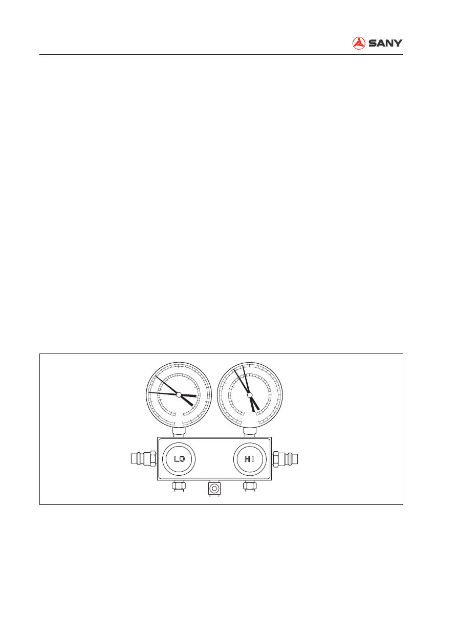
6.  Fault testing with manifold pressure gauge


Refrigerating system under normal condi-
tion

Gauge reading:

Lo-pressure end:

0.15~0.25 Mpa (1.5~2.5 Kgf/cm²)

Hi-pressure end:

1.37~1.57 Mpa (14~16 Kgf/cm²)

After the engine has been preheated, read the 
pressure value on the gauge under the follow-
ing conditions:

1)  Temperature at air inlet: 30 – 35°C

2)  Engine speed: 1500 rpm

3)  Fan speed: High

4)  Temperature control: Minimum.

5)  Air circulation mode: Recirculation

ZX215-1002167

0

0

01

02

03

04

05

05

0

0

35

MPa

MPa

{cmHg   kgf/cm

2

}

{cmHg   kgf/cm

2

}

5

3

30

25

25

20

10

1

15

2

15

35

-01

-01

-76

-76

-50

06

07

08

R134a

085

8.5

8

7

5

6

4

3

2

1

15

Structure and Function

SY215C

LC

4-157

Symptom

Cause

Analysis

Remedy


When the system is 
operating, pressure 
at the Lo-pressure 
end unstable (some-
times vacuum, 
sometimes normal)


Moisture in the system 
ices up at the expan-
sion valve causing 
circular temporary 
stop. When ice melts, 
the system becomes 
normal again.


Over-saturation of de-
hydrator.


Moisture in the system 
ices up at the expan-
sion valve and hinders 
the circulation of the 
refrigerating system.


Replace receiver/
dehydrator


Remove the mois-
ture in the system 
through constant 
pumping.


Add proper volume 
of new refrigerant.


Moisture in the refrigerating system

Symptom: Intermittent refrigeration to non-refrigeration

ZX215-1002168

0

0

01

02

03

04

05

05

0

0

35

MPa

MPa

{cmHg   kgf/cm

2

}

{cmHg   kgf/cm

2

}

5

3

30

25

25

20

10

1

15

2

15

35

-01

-01

-76

-76

-50

06

07

08

085

8.5

8

7

5

6

4

3

2

1

15

Structure and Function

SY215C

LC

4-158


Insuf

fi

 cient refrigeration

Symptom: Insuf

fi

 cient refrigeration 

Symptom

Cause

Analysis

Remedy


Pressure at both Hi- and 
Ho-pressure ends very 
low


Foam is continuously ob-
served via the sight glass


Insuf

fi

 cient refrigeration.


Air leaks 
somewhere 
in the refrig-
erating sys-
tem


Insuf

fi

 cient 

refrigerant in the 
system


Leak of refriger-
ant


Check for air leakage with a leak 
detector. Make necessary re-
pairs.


Add proper amount of refriger-
ant.


When connected with the gauge, 
if the reading is near zero, set 
the system under vacuum state 
after inspection  and repair.

ZX215-1002169

0

0

01

02

03

04

05

05

0

0

35

MPa

MPa

{cmHg   kgf/cm

2

}

{cmHg   kgf/cm

2

}

5

3

30

25

25

20

10

1

15

2

15

35

-01

-01

-76

-76

-50

06

07

08

085

8.5

8

7

5

6

4

3

2

1

15

Structure and Function

SY215C

LC

4-159


Defective refrigerant circulation

Symptom: insuf

fi

 cient refrigeration

Symptom

Cause

Analysis

Remedy


Pressure at both 
Hi- and Lo-pressure 
sides very low


Frosting on the pip-
ing between parts 
and reservoir


Contaminant in the 
reservoir hinders the 

fl

 ow of refrigerant.


Blocked reservoir


Replace reservoir

ZX215-1002170

0

0

01

02

03

04

05

05

0

0

35

MPa

MPa

{cmHg   kgf/cm

2

}

{cmHg   kgf/cm

2

}

5

3

30

25

25

20

10

1

15

2

15

35

-01

-01

-76

-76

-50

06

07

08

085

8.5

8

7

5

6

4

3

2

1

15

Structure and Function

SY215C

LC

4-160


Refrigerant not circulating

Symptom: Non-refrigeration (intermittent refrigeration)

Symptom

Cause

Analysis

Remedy


Vacuum at Lo-pres-
sure side; pressure 
at Hi-pressure side 
extremely low


Frosting or conden-
sation on the pipes 
around the expan-
sion valve or receiv-
er/dehydrator


Moisture or contami-
nant in the refrigerant 
hinders the 

fl

 ow of 

refrigerant.


Air leak at the thermal 
pipe of the expansion 
valve hinders the 

fl

 ow 

of refrigerant.


Refrigerant not 
circulating


Check the expansion valve 
and ERP.


Blow the contaminant in the 
expansion valve or replace 
the expansion valve if nec-
essary.


Replace the receiver


Release internal air and 
add refrigerant. If air leaks 
from thermal pipe, replace 
expansion valve.

ZX215-1002171

0

0

01

02

03

04

05

05

0

0

35

MPa

MPa

{cmHg   kgf/cm

2

}

{cmHg   kgf/cm

2

}

5

3

30

25

25

20

10

1

15

2

15

35

-01

-01

-76

-76

-50

06

07

08

085

8.5

8

7

5

6

4

3

2

1

15

Structure and Function

SY215C

LC

4-161


Over-charging of refrigerant or insuf

fi

 cient refrigeration of condenser

Symptom: Insuf

fi

 cient refrigeration

Symptom

Cause

Analysis

Remedy


Pressure at both Hi-
and Lo-pressure 
sides very high


No foam can be ob-
served via the sight 
glass even when 
engine speed drops.


Over-

fi

 lling of refriger-

ant in the system. Re-
frigerating performance 
inadequate.


Insuf

fi

 cient refrigera-

tion of condenser


Over-

fi

 lling of refriger-

ant


Condenser 

fi

 ns clogged 

or fan motor error.


Clean the condenser


Check the working 
condition of fan  mo-
tor


If the two above 
items are normal, 
check the volume 
of refrigerant. Add 
refrigerant.

ZX215-1002172

0

0

01

02

03

04

05

05

0

0

35

MPa

MPa

{cmHg   kgf/cm

2

}

{cmHg   kgf/cm

2

}

5

3

30

25

25

20

10

1

15

2

15

35

-01

-01

-76

-76

-50

06

07

08

085

8.5

8

7

5

6

4

3

2

1

15

Structure and Function

SY215C

LC

4-162


Air is observed in the refrigerating system

Symptom: Poor refrigeration

  If refrigerant is added with no evacuation operation performed, the following gauge reading 

will appear:

Symptom

Cause

Analysis

Remedy


Pressure at both Hi- and 
Lo-pressure ends very 
high


Lo-pressure piping feel-
ing hot


Foam is observed 
through the sight glass


Air enters the re-
frigerating system


Air enters the refriger-
ant system


Insuf

fi

 cient evacuation 


Check if compressor 
oil is contaminated 
or inadequate.


Evacuate and add 
new refrigerant.

ZX215-1002173

0

0

01

02

03

04

05

05

0

0

35

MPa

MPa

{cmHg   kgf/cm

2

}

{cmHg   kgf/cm

2

}

5

3

30

25

25

20

10

1

15

2

15

35

-01

-01

-76

-76

-50

06

07

08

085

8.5

8

7

5

6

4

3

2

1

15

Structure and Function

SY215C

LC

4-163


Improper installation of expansion valve/thermal pipe defect (wide opening)

Symptom: insuf

fi

 cient refrigeration

Symptom

Cause

Analysis

Remedy


Pressure at both 
Hi- and Lo-pressure 
ends very high


Frosting or conden-
sation on Lo-pres-
sure piping


Expansion valve de-
fect, or improper instal-
lation of thermal pipe


Over-

fi

 lling of 

refrigerant in 
Lo-pressure 
piping


Expansion 
valve opening 
very wide


Check the installation of 
thermal piping


If thermal piping is normal, 
check the expansion valve. 
Replace defective expan-
sion valve if observed.

ZX215-1002174

0

0

01

02

03

04

05

05

0

0

35

MPa

MPa

{cmHg   kgf/cm

2

}

{cmHg   kgf/cm

2

}

5

3

30

25

25

20

10

1

15

2

15

35

-01

-01

-76

-76

-50

06

07

08

085

8.5

8

7

5

6

4

3

2

1

15

Structure and Function

SY215C

LC

4-164


Compressing error

Symptom: No refrigeration

Symptom

Cause

Analysis

Remedy


Pressure at Lo-pressure 
side very high


Pressure at Hi-pressure 
side very low


Compressor internal 
leakage


Compressing fault; 


Leaking or damaged 
valve, loosened parts


Repair or replace 
compressor

ZX215-1002175

0

0

01

02

03

04

05

05

0

0

35

MPa

MPa

{cmHg   kgf/cm

2

}

{cmHg   kgf/cm

2

}

5

3

30

25

25

20

10

1

15

2

15

35

- 01

-01

-76

-76

-50

06

07

08

085

8.5

8

7

5

6

4

3

2

1

15

Structure and Function

SY215C

LC

4-165

4.7.14 Compressor oil

Oil shall be added into the A/C system for 
lubrication. Compressor oil is solved in the 
refrigerant and circulates in the system. When 
the air conditioning system is shut down, com-
pressor oil will stay inside the components. If 
no compressor oil is added into the system 
when replacing components, inadequate lubri-
cation will result. Add compressor oil accord-
ing to the chart below:


Add oil into a new compressor ac-
cording to the required volume of the 
system. When the compressor is to be 
replaced, discharge the surplus oil in it. 


Over-filling of compressor oil will re-
duce the refrigerating capacity. Short of 
compressor oil in the system will cause 
compressor abnormality.


Protect pipe joints and O-rings from 
contamination when disassembling the 
compressor. 

Replaced component

Compressor

Condenser

Evaporator

Volume(CC)

See "CAUTION" below

40

40

Compressor oil grade

ND8# (10P, 10PA, 10S series compressor)

ND9#(TV series compressor)

CAUTION

Structure and Function

SY215C

LC

4-166

4.8  

Engine Control

1- Battery relay
2- Battery
3-  Engine start switch
4-  Fuel control dial
5- Start motor
6- Engine controller
7-  Fuel injection pump
8- Throttle motor
9- Shutdown device

Outline


Start and stop the engine only with the  en-
gine start switch (3).


The controller (6) receives the signal from 
the fuel control dial (4) and transmits the 
drive signal to the throttle motor (8) to 
control the governor lever angle of fuel 
injection pump (7) and control the engine 
speed.


When engine start switch (3) is turned to 
the OFF position, the shutdown device (9) 
closes the injection nozzle of the fuel injec-
tion pump and cuts the engine fuel supply. 
Then, the engine stops. 

ZX215-1002176

4

3

2

5

9

1

Z

8

7

6

Structure and Function

SY215C

LC

4-167

4.8.1  System operation  

4.8.1.1 Engine startup


When the start switch is turned to the 
START position, the starting signal is trans-
mitted to the start motor. Then, the start 
motor rotates to start the engine.
When it happens, the engine controller 
checks the signal voltage from the fuel 
control dial and sets the engine speed to 
the speed set by the fuel control dial.

4.8.1.2  Engine speed control


The fuel control dial sends a signal voltage 
corresponding to the rotation angle to the 
engine controller.

The engine controller sends a driving 
signal to the throttle motor according to the 
signal voltage to control the fuel injection 
pump, and eventually controls the engine 
speed.

4.8.1.3 Engine shutdown


When the start switch is turned to the OFF 
position, the controller activates the shut-
down device to cut off the fuel supply and 
stops the engine. 

ZX215-1002177

C

BR

P

M

s

Lo

Lo

Hi

Hi

B

P

P

E

E

E

B

L

SW

S

B

s

(Regulating signal

)

Engine

(Power)

Controller

(Start switch ON signal)

(Starting signal)

Start S/W

Fuel ctrl dial

Throttle On

Governor
motor

Alternator

Bat. relay

Lock
relay

Shutdown
device

Shutdown 

relay

(Starting signal)

Safety
relay

Drive signal

(Potentiometer singal)

Throttle Off

Pilot S/W

Start motor

Starting relay

ZX215-1002178

C

BR

P

M

s

Lo

Lo

Hi

Hi

B

P

P

E

E

E

B

L

SW

S

B

s

Throttle On

(Regulating signal

)

Governor
motor

Alternator

Bat. relay

Lock
relay

Engine

(Power)

Controller

(Start switch ON signal)

Start motor

Shutdown
device

Shutdown 

relay

(Starting signal)

(Starting signal)

Safety
relay

Drive signal

(Potentiometer singal)

Throttle Off

Starting relay

Pilot S/W

Start S/W

Fuel ctrl dial

ZX215-1002179

C

BR

s

Lo

Lo

Hi

Hi

B

P

P

E

E

E

B

L

SW

S

B

s

Throttle On

(Regulating signal

)

Governor
motor

Alternator

Bat. relay

Lock
relay

Engine

(Power)

Controller

(Start switch ON signal)

Start motor

Shutdown
device

Shutdown 

relay

(Starting signal)

(Starting signal)

Safety
relay

Throttle Off

Starting relay

Pilot S/W

Start S/W

Fuel ctrl dial

Structure and Function

SY215C

LC

4-168

4.8.2  

Components

4.8.2.1  

Fuel control dial

1- Knob
2- Dial
3- Spring

4- Ball
5- Potentiometer
6- Connector

ZX215-1002180

25°

140°

9×10°

1

2

3

4

5

5V

0V

VR

1

2

3

6

1

2

3

Yellow

Blue

Red

Level 1

Left limit

Right limit

Level 10

Structure and Function

SY215C

LC

4-169

Function


Turning of the fuel control dial changes the 
resistance of the sliding rheostat inside the 
dial and the voltage signal collected by the 
controller. The controller calculates the col-
lected signals and drives the throttle motor 
via signal output and controls the volume 
of the injection pump so that the engine 
can run at an optimal speed.


When throttle voltage is beyond the area, 
the controller sends out alarm code and 
the engine runs at low idle. The area under 
the sloping line is the abnormality detection 
area. 

Remark: 

The left limit is 0%; and the right limit is 100%. 

ZX215-1002181

%

V

100

0

0.25 1.72

4.49 4.75 5

Voltage

V

Dial angle

Structure and Function

SY215C

LC

4-170

4.8.2.2  

Controller

Controller port layout

ZX215-1002182

TYPE

USE FOR
NO

A

ZX215-1002183

........

........

........

........

...................

...................

...................

...................

A1

A2

Structure and Function

SY215C

LC

4-171

A1

Pin 

No.

Signal name

Input/

output

53

Rear pump pressure sensor

Input

54

Sensor power ground

Input

55

Sensor power ground

Input

56

Sensor power

Output

60

Monitor CAN Low

61

Calibrator CAN High

62

Calibrator CAN Low

66

Coolant temp very high

Input

67

R. travel pressure sensor

Input

68

Swing pressure sensor

Input

69

Bucket CURL pressure sensor

Input

70

Boom RAISE pressure sensor

Input

71

Arm IN pressure sensor

Input

72

Front pump pressure sensor

Input

73

Sensor PWR ground

74

Sensor PWR

Output

75

Sensor PWR

Output

76

State indicator

77

Monitor CAN High

78

Monitor CAN Low

79

Setting tool CAN Low

80

Setting tool CAN shield wire

81

Setting tool CAN High

A2

Pin 

No

.

Signal name

Input/

output

82

Travel speed switching solenoid

88

Front pump solenoid valve

89

Rear pump solenoid valve

97

Swing priority solenoid valve

98

Bucket con

fl

 uence solenoid valve

99

Boom priority 1

100 Boom priority 2
104 Motor drive signal +

113 Motor drive signal -
114 Power ground
115 Power ground
116 Power ground
117 Power ground
118 Power supply(24V constant)
119 Power supply(24V constant)

120 Power supply(24V constant)
121 Power supply(24V constant)

A1

Pin 

No.

Signal name

Input/

output

1

Power ground

2

Power ground

3

Power ground

4

Power supply(24V constant)

Input

5

Power supply(24V constant)

Input

11

Fuel level sensor

Input

15

Throttle position signal

Input

19

Engine speed signal

Input

22

RS232 ground

23

RS232 receive

24

Enable

30

Coolant temperature sensor signal Input

31

Oil temperature sensor signal

Input

33

Backup pilot pressure signal

Input

34

Fuel dial signal

Input

38

Engine speed signal ground

41

RS232 send

42

CPU mode

43

Enable

48

Engine oil pressure switch

Input

49

L. travel pressure sensor

Input

50

Bucket DUMP pressure sensor

Input

51

Boom LOWER pressure sensor

Input

52

Arm OUT pressure sensor

Input

Input and output signals


Content      ..     14      15      16      17     ..