SANY Crawler Hydraulic Excavator SY215CLC (CUMMINS QSB6.7 engine). Shop Manual - page 14
 

  Index      Manuals     SANY Crawler Hydraulic Excavator SY215CLC (CUMMINS QSB6.7 engine). Shop Manual


Search            copyright infringement  


Content      ..     12      13      14      15     ..


SANY Crawler Hydraulic Excavator SY215CLC (CUMMINS QSB6.7 engine). Shop Manual - page 14


Structure and Function

SY215C

LC

4-124

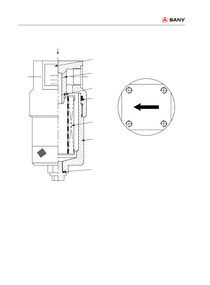
4.6.11 Pilot oil fi lter

ZX215-1002127

Model
Pressure
Precision

1

K

2

3

3

4

5

6

1- Name plate
2- Head cover
3- O-ring
4- Seal
5- Filter
6- Case

Max. delivery: 40 L/min
Filter 

fi

 neness: 10 

μ

m

Operating pressure: 20 Mpa
Max. operating pressure: 40 Mpa
Pressure loss: 0.05 Mpa
Max. allowable pressure difference: 1 Mpa
Speci

fi

 cation of inlet/outlet port o-ring: 30×3.1

Specifi cations

Structure and Function

SY215C

LC

4-125

4.6.12  Pump oil pressure sensor

Function


This sensor measures pump oil pressure 
and uses it to control various machine op-
erations. When oil pressure compresses 
the diaphragm, it deforms and this is de-
tected in the form of electric signals. 

1-  1/8NPT Pressure connector
2- Name plate
3- Connector
4- Vent hole

ZX215-1002128

A

B

C

4

1

2

3

Structure and Function

SY215C

LC

4-126

4.6.13 Hydraulic cylinder

Boom cylinder

Arm cylinder

Bucket cylinder

ZX215-1002129

2

1

3

267±35N.m

27.2±3.6kgm

56.9±10.7N.m

5.8±1.1kgm

544.9±5.1kgm

5340±50N.m

ZX215-1002130

2

1

3

37.4±3.6kgm

367±35N.m

56.9±10.7N.m

5.8±1.1kgm

806.1±5.1kgm

7900±50N.m

ZX215-1002131

2

1

3

27.2±3.6kgm

267±35N.m

5.8±1.1kgm

56.9±10.7N.m

559.2±5.1kgm

5480±50N.m

Structure and Function

SY215C

LC

4-127

100 hours greasing

Unit: mm

No.

Check item

Criteria

Remedy

1

Clearance between pis-
ton rod and  bushing

Cylinder

Standard 

size

Tolerance

Standard 

clearance

Clearance 

limit

Replace 

bushing

Shaft

Hole

Boom

85

-0.036 +0.222

0.083 – 0.312

0.412

-0.090 +0.047

Arm

95

-0.036 +0.222

0.083 – 0.312

0.412

-0.090 +0.047

Bucket

80

-0.030 +0.258

0.078 – 0.334

0.434

-0.076 +0.048

2

Clearance between pis-
ton rod support pin and 
bushing

Boom

80

-0.030 +0.246

0.230 – 0.322

1.0

Replace 

pin or 

bushing

-0.076 +0.200

Arm

80

-0.030 +0.246

0.230 – 0.322

1.0

-0.076 +0.200

Bucket

70

-0.030 +0.246

0.230 – 0.322

1.0

-0.076 +0.200

3

Clearance between cyl-
inder bottom support pin 
and bushing

Boom

70

-0.030 +0.246

0.230 – 0.322

1.0

-0.076 +0.200

Arm

80

-0.030 +0.246

0.230 – 0.322

1.0

-0.076 +0.200

Bucket

70

-0.030 +0.246

0.230 – 0.322

1.0

-0.076 +0.200

500 hours greasing

Unit: mm

No.

Check item

Criteria

Remedy

1

Clearance between pis-
ton rod and bushing

Cylinder

Standard 

size

Tolerance

Standard 

clearance

Clearance 

limit

Replace 

bushing

Shaft

Hole

Boom

85

-0.036 +0.222

0.083 – 0.312

0.412

-0.090 +0.047

Arm

95

-0.036 +0.222

0.083 – 0.312

0.412

-0.090 +0.047

Bucket

80

-0.030 +0.258

0.078 – 0.334

0.434

-0.076 +0.048

2

Clearance between pis-
ton rod support pin and 
bushing

Boom

80

-0.030 +0.246

0.230 – 0.322

1.0

Replace 

pin or 

bushing

-0.076 +0.200

Arm

80

-0.030 +0.246

0.230 – 0.322

1.0

-0.076 +0.200

Bucket

70

-0.030 +0.246

0.230 – 0.322

1.0

-0.076 +0.200

3

Clearance between cyl-
inder bottom support pin 
and bushing

Boom

70

-0.030 +0.246

0.230 – 0.322

1.0

-0.076 +0.200

Arm

80

-0.030 +0.246

0.230 – 0.322

1.0

-0.076 +0.200

Bucket

70

-0.030 +0.246

0.230 – 0.322

1.0

-0.076 +0.200

Structure and Function

SY215C

LC

4-128

4.6.14 Work equipment

Dimensions

ZX215-1002133

A

B

C

D

E

F

G

H

,

J

K

ZX215-1002134

1

5

6

3

4

2

A-A

F-F

G-G

H-H

C-C

D-D

E-E

K-K

J-J

,

-

,

B-B

Structure and Function

SY215C

LC

4-129

Greasing

Unit: mm

No.

Check item

Bush 

material

Greasing 

interval

Criteria

Remedy

1

Clearance between pin 
connecting boom and 
revolving frame and 
bushing

Alloy

500 h

Standard 

size

Tolerance

Standard 

clearance

Clearance 

limit

Replace

Shaft

Hole

Φ

 100

–0.036
–0.071

+0.171
+0.084

0.120 ~ 

0.242

1.0

2

Clearance between pin 
connecting boom and 
arm and bushing

Steel

100 h

Φ

 100

–0.036
–0.071

+0.282
+0.240

0.276 ~ 

0.353

1.0

3

Clearance between pin 
connecting arm and 
rocker and bushing

Steel

100 h

Φ

 90

–0.036
–0.071

+0.338
+0.272

0.308 ~ 

0.409

1.0

4

Clearance between pin 
connecting arm and 
bucket and bushing

Steel

100 h

Φ

 90

–0.036
–0.071

+0.336
+0.275

0.311 ~ 

0.407

1.0

5

Clearance between pin 
connecting linkage and 
bucket and bushing

Steel

100 h

Φ

 90

–0.036
–0.071

+0.338
+0.272

0.308 ~ 

0.409

1.0

6

Clearance between pin 
connecting linkages and 
bushing

Steel

100 h

Φ

 90

–0.036
–0.071

+0.338
+0.272

0.308 ~ 

0.409

1.0

Structure and Function

SY215C

LC

4-130

ZX215-1002135

1

2

3

4

5

6

7

8

9

10

11

12

13

14

15

16

17

18

A

A

B

B

C

C

D

D

A-A

B-B

C-C

D-D

Arm dimension

Structure and Function

SY215C

LC

4-131

Unit: mm

No.

Standard size

Tolerance

1

φ

80

+0.1

0

2

107

+1.5

0

3

310

-0.3
-0.8

4

φ

90

+0.174
+0.104

5

365.6

±1

6

187.2

±0.5

7

829.1

±1

8

2,919

9

2,631.3

±1

10

411

11

640

±0.2

12

600

±0.5

13

458

14

φ

80

+0.373
+0.273

15

325

0

-0.5

16

φ

80

+0.1

0

17

Arm itself

311

0

-0.5

When press 

fi

 tting bushing

325

18

Min.

1,680

Max.

2,800

Structure and Function

SY215C

LC

4-132

4.7  Air Conditioning System

1-  Hot water piping 
2-  A/C compressor (DENSO.2)
3- Refrigeration piping
4- Condenser (SG447750-A040)
5- Reservoir (DENSO.4)
6-  Hot water return piping

7- Refrigeration unit
8- Air duct
A. Fresh air

B. Recirculated air

C. Warm air/cool air

ZX215-1002137

C

8

7

6

5

4

3

2

1

C

C

C

C

A

B

Structure and Function

SY215C

LC

4-133

4.7.1  A/C components layout drawing

1- Sunlight sensor
2- Control panel
3-  Air conditioning unit
4- Condenser

5- Compressor
6-  Fresh air sensor
7-  Recirculated air sensor

ZX215-1002138

1

2

3

4

5

6

7

Structure and Function

SY215C

LC

4-134

Remark:

When Auto mode switch (5), Air circulation 
control switch (6) and A/C switch (8) are 
turned on, indicator lights above these switch-
es will light up.

4.7.2 Control panel

1- OFF switch
2-  Fan speed control switch
3-  Temperature control switch
4-  Air outlet mode switch
5-  Auto mode switch

6-  Air circulation control switch
7- LCD display
8- A/C switch
9- Sunlight sensor

ZX215-1002139

6

1

2

3

4

5

7

8

Monitor

9

FULL AUTO AIRCONDITION

OFF

TEMP

MODE

AUTO

A/C

Structure and Function

SY215C

LC

4-135

4.7.3 Circuit diagram

ZX215-1002140

M

M

CM

1.256

1.25L

M

M

M

25

30

29

28

27

23

15

15

33

15

15

15

15

12

14

13

13

13

15

15

10

8

8

8

8

13

7

9

9

1

1

1

2

2

2

7

4

4

4

3

3

3

02

02

02

02

03

03

02

02

01

06

06

7

5

5

5

6

10

10

10

10

12

12

11

16

16

16

19

19

17

18

21

22

25

22

24

26

25

22

20

31

30

31

32

22

22

32

32

34

34

35

35

35

24

26

M

M

RF

GND

Pt

Vz

REC

FFE

28

G

8

6

BLCM

SP

HL

0.5B

AC

M

M

AM

S

SD

TH

F

TH

I

TH

W

TH

AM

M

V1

M

V2

2G

2RL

M

R

D

D

1

ACC

200W

0.50

2B

2B

80W

1.25B

1.25B

0.85B

2B

40W

BLC

RL

CH

43

2

1

EC

C

RL

CH

R

CD

BA

T

40A

FL

Z

CM

B

60A

15A

20A

1.25R

+B

RL

SF

G

CM

B

RL

CH

RL

CD

RL

CC

SP

CD

M

CD

RL

BM

FU

CD

FU

RM

FL

1

D

2

SW

1.25RL

15

19

16

14

12

13

16

27
4

21
20

22

23

1

22

4

25
9

38

26

10

3

RL

BM

RL

CD

RL

CC

FU

M

1.25R

H

OFF

B

G

1

G

2

ACC
MS
T

ACC

ON

START

SW 

5A

Structure and Function

SY215C

LC

4-136

Wire No. Diameter/Color code

Wire color

Wire No. Diameter/Color code

Wire color

B

Black

0.5VW

Violet+white

Br(R)

Brown

0.5YB

Yellow+black

0.85W

White

0.5WO

White+orange

RL

Red+blue

0.5PB

Pink+black

G

Green

0.5VR

Violet+red

0.5BL

Black+blue

0.5BG

Black+green

0.5R

Red+blue

0.5WY

White+yellow

0.5Y

Yellow

0.5WR

White+red

0.5BR

Black+red

0.5BrW

Brown+white

0.5BrY

Brown+yellow

0.5GO

Green+orange

0.5BY

Black+yellow

0.5Sb

Sky blue

0.5GW

Green+white

0.5OW

Orange+white

0.5LO

Blue+orange

1.25V

Violet

0.5PG

Pink+green

1.25RG

Red+green

0.5RY

Red+yellow

1.25RW

Red+orange

0.5BW

Black+white

0.85GL

Green+Blue

0.5LgR

Light green+red

Code

Name

Code

Name

Code

Name

AC

M

A/C ampli

fi

 er

FU

CD

Condenser fuse

RL

CH

Condenser high speed 

relay

BAT

Battery

FU

M

A/C main fuse

RL

SF

Protective relay

BLC

Speed regulating resistor

G

Alternator

S

SD

Sunlight sensor

CM

B

Battery relay

M

AM

A/M servo motor

SP

CD

Condenser pressure 

switch

D

Diode

M

B

Blower motor

SP

HL

HI/LO pressure switch

D

1

Diode 1

M

CD

Condenser motor

SW

Switcher

D

2

Diode 2

M

RF

Internal/External air servo 

motor

TH

AM

External air thermistor

EC

C

Compressor clutch

M

V1

Air outlet servo motor

TH

F

Anti-frosting thermistor

FL

1

Fuse

M

V2

FRONT outlet servo motor

TH

I

Internal air thermistor

FL

2

Fuse

R

CD

Condenser resistor

TH

W

Water temp. thermistor

FU

BM

Blower fuse

RL

BM

Blower main relay

RL

CC

Compressor relay

RL

CD

Condenser relay

Structure and Function

SY215C

LC

4-137

4.7.4 Refrigeration principle

4.7.4.1  Refrigeration cycle diagram

4.7.4.2  Heating cycle diagram

ZX215-1002141

Cool air

Lo-pressure part

Hot air

Hi-pressure part

Lo temp\Lo press\Gas

Air in cab

Out side fresh air

Cooling fan

Lo temp\Lo press\Liquid (Mist)

Hi temp\Hi press\Liquid

Lo-pres.
side

Hi-pres.
side

Compressor

Blower motor

Evaporator

Reservoir

Expansion valve

Hi-temp hi-pres gas

ZX215-1002142

Engine

Water pump

Water valve control

Blower motor

Internal air

Low tempr water

High temp water

Hot air

Radiator

Structure and Function

SY215C

LC

4-138

4.7.5 Compressor

1- Stator
2-  Front radial bearing
3- Thrust bearing
4-  Front radial bearing
5-  Rear cylinder head
6- Safety valve
7-  Rear cylinder block
8- Swash plate

9- Slipper
10-  Front cylinder block
11- Piston
12-  Front cylinder head
13- Shaft seal
14- Main shaft
15- Hub
16- Rotor

ZX215-1002143

1

2

3

4

5

6

7

8

9

10

11

12

13

14

15

16

Structure and Function

SY215C

LC

4-139

Operating principle

Compressor type: 10S15C. This compres-
sor has 5 plungers in total with a piston on 
both sides of each plunger. The rotation of 
the swash plate drives the pistons to move 

back and forth and transforms the refrigerant 
sucked from the evaporator from low tempera-
ture and low pressure gas state to high tem-
perature and high pressure state.

ZX215-1002144

Process


1

Process


6

Process


5

Process


3

Process


2

Process


4

HI press.end pipe

HI press.end pipe

HI press.end pipe

HI press.end pipe LO press.end pipe

LO press.end pipe

LO press.end pipe

LO press.end pipe

HI press.end pipe LO press.end pipe

Valve plate

Outlet valve disc

Main shaft and swash plate

HI press.end pipe LO press.end pipe

Intlet valve disc


Content      ..     12      13      14      15     ..