SANY Crawler Hydraulic Excavator SY215CLC (CUMMINS QSB6.7 engine). Shop Manual - page 13
 

  Index      Manuals     SANY Crawler Hydraulic Excavator SY215CLC (CUMMINS QSB6.7 engine). Shop Manual


Search            copyright infringement  


Content      ..     11      12      13      14     ..


SANY Crawler Hydraulic Excavator SY215CLC (CUMMINS QSB6.7 engine). Shop Manual - page 13


Structure and Function

SY215C

LC

4-108

ZX215-1002111

Pressure

Time

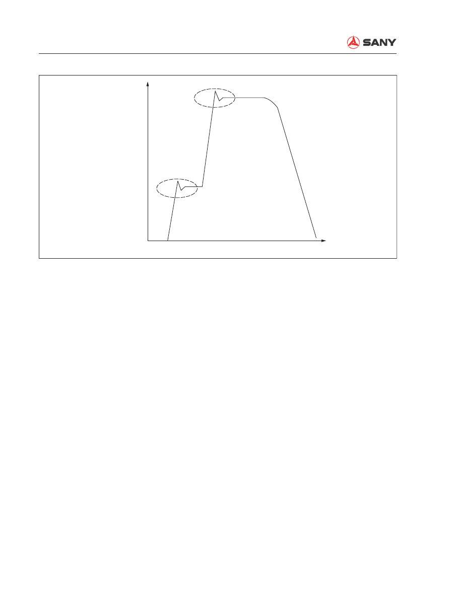
Damping method

Structure and Function

SY215C

LC

4-109

Table 2  Repair standard of motor components

Components

Check item

Allowable limit

Remedy

1-4-2 Plunger 
assembly

1. Sliding surface of the slid-
ing shoe

Roughness 0.8a or surface rough-
ness, scratch >0.02mm

Grind sliding surface; 
replace 4 cylinder block  
assembly parts if unre-
pairable

2. Outside diameter of 
plunger

Roughness 1.2a or surface rough-
ness, scratch >0.02mm

Replace 4 cylinder 
block assemblies

3. Plunger outside diameter, 
and 4-1 cylinder bore

Clearance 0.060. 

4. Sliding shoe ball end 
clearance

Clearance 0.4. 

1-4-1 Cylinder 
block

1. Valve leaf and sliding sur-
face

Roughness 0.8a or surface rough-
ness, scratch >0.02mm. 

Grind sliding surface; 
replace 4 cylinder block 
assembly parts if unre-
pairable

2. Shaft hole inner diameter

Roughness 1.6a or surface rough-
ness, scratch >0.02mm

Replace 4 cylinder 
block assembly

3. Shaft hole inner diameter, 
4-2 piston assembly outer 
diameter

Clearance 0.060

4. Spline at shaft joint

Roller distance below 38.749 
(measuring pin diameter 

φ

3.333(V1=2.80)); or damaged

1-21 Oil distrib-
uting plate

1. Sliding surface

Roughness 0.8a, scratch >0.02mm 
on sliding surface or burned sign

32 Grind sliding surface 
or replace 22 valve 
sheet if unrepairable

1-4-3 Retainer
1-4-4 Retaining 
assembly

1. Sliding surface

Roughness 0.8a, scratch >0.02mm 
on sliding surface or sign of burning

Replace retaining plate 
or retaining assembly.

1-5 Swash 
plate

1. Sliding surface

Roughness 0.8a, abrasion on sling 
surface or scratch >0.02mm

1-4-1 grind sliding sur-
face or replace 22 valve 
sheet if unrepairable

2. Ball hole on assembly 
steel ball portion

Roughness 1.6a. 

Replace swash plate

Scratch on spherical surface 
>0.02mm or surface roughness

3. Ball hole on assembly 
steel ball portion

Ball depth 14.5

Structure and Function

SY215C

LC

4-110

Components

Check item

Allowable limit

Remedy

1-3 Shaft

1. Sliding port of oil seal 
outer diameter

Roughness 1.6a oil seal lip sliding 
sign. Scratch >0.02mm or surface 
roughness

Replace swash plate

2. Spline of cylinder block

Roller distance below 47.380(mea-
suring pin diameter 

φ

3.00); or dam-

aged

Replace shaft

3. Drive gear connection

Roller distance below 30.498 (mea-
suring pin diameter 

φ

3.33); or dam-

age

1-15 Brake 
piston

1. Dimension

Height 38.2 

Replace brake piston

2. Sliding surface

Roughness 2.5a 

3. Appearance

Scratch 0.02mm+ or surface rough-
ness 

1-13 Disc plate

1. Dimension

Thickness 3.2

Replace disc plate

2. Appearance

Deep scratch on sliding surface or 
friction material peeling

1-8 Ball bear-
ing
1-9 Ball bear-
ing

1. Rolling surface

Peeling or fracture

Replace ball bearing

2. Action 

Abnormal rotation (noise/uneven 
rotation) 

1-7 Piston as-
sembly

1. Sliding shoe sliding sur-
face

Roughness 1.6a, surface rough-
ness, scratch >0.02mm

Grind sliding surface; 
replace 

fl

 ange plate 

parts if unrepairable

2. Piston outer diameter

Roughness 1.2a, surface rough-
ness, scratch >0.02mm

Replace 

fl

 ange plate 

parts

3. Piston outer diameter and 
1-1 

fl

 ange plate part inner 

diameter

Roughness 0.8 a, scratch >0.02mm 
or surface roughness 0.040. 

4. Ball end clearance of slid-
ing shoe

Roughness 0.8 a, scratch >0.02mm 
or surface roughness 1.0. 

1-2-2 Piston 
assembly

1. Piston outer diameter

Roughness 0.8 a, scratch >0.02mm 
or surface roughness. 

Replace valve sheet

2. Piston outer diameter and 
valve sheet inner diameter

Roughness 0.8 a, scratch >0.02mm 
or surface roughness 0.060. 

Structure and Function

SY215C

LC

4-111

Components

Check item

Allowable limit

Remedy

1-2-1 Valve 
sheet

1. Assembly 2-2 piston as-
sembly hole

Roughness 0.8 a, scratch >0.02mm 
or surface roughness

Replace valve sheet 
and parts

2. Valve sheet inner diame-
ter and piston outer diameter

Roughness 0.8 a, scratch >0.02mm 
or surface roughness 0.060

3. Assembly 2-11 sliding 
valve spool assembly hole

Roughness 0.8 a, scratch >0.02mm 
or surface roughness

4. Sliding valve sheet inner 
diameter and valve spool 
outer diameter

Roughness 0.8 a, scratch >0.02mm 
or surface roughness 0.060. 

5. Relief valve assembly 
sliding piston and valve seat

Scratch >0.02mm or surface rough-
ness

1-2-9 Spool as-
sembly

1. Valve spool out diameter

Roughness 0.8 a, scratch >0.02mm 
or surface roughness

Replace valve sheet 
and parts

2. Slide valve spool outer 
diameter and valve sheet 
inner diameter

Roughness 0.8 a, scratch >0.02mm 
or surface roughness 0.060. 

1-2-7-9 Mov-
able piston

1. Sliding portion of valve 
sheet and valve seat

Scratch >0.02mm or surface rough-
ness

Replace relief valve as-
sembly

1-2-7-1 Case

1. Sling portion of the mov-
able piston (outer diameter)

Scratch >0.02mm or surface rough-
ness

1-4-7 Spring

1. Dimension

Free length 61.0

2. Appearance

Deformation and surface damage

1-18 Spring

1. Dimension

Free length 39.0

2. Appearance

Deformation and surface damage

1-20 Spring

1. Dimension

Free length 41.5

2. Appearance

Deformation and surface damage

1-2-4 Spring

1. Dimension

Free length 48.5

2. Appearance

Deformation and surface damage

1-2-10 Spring

1. Dimension

Free length 28.3

2. Appearance

Deformation and surface damage

O-ring and oil 
seal

When being removed

Replace o-ring and oil 
seal

Structure and Function

SY215C

LC

4-112

4.6.7  Valve control system

9

8

7

6

10

4

3

2

1

5

13

12

11

1

2

3

4

5

6

7

8

9

10

11

12

ZX215-1002112

Structure and Function

SY215C

LC

4-113

1-  Travel PPC valve
2-  L. travel control lever
3-  R. travel control lever
4-  Right PPC valve
5- Right joystick
6- Accumulator
7- Transition block
8- Hydraulic pump
9-  Main control valve
10- Solenoid valve
11- Left joystick
12- Relay

 (1) HOLD
 (2) Boom UP
 (3) Boom DOWN
 (4) Bucket DUMP
 (5) Bucket DIG
 (6) HOLD
 (7) Arm IN
 (8) Arm OUT
 (9) Right swing
 (10) Left swing
 (11) Neutral
 (12) Forward travel
 (13) Backward travel

Control lever position

Structure and Function

SY215C

LC

4-114

4.6.8  Pilot  valve

4.6.8.1  Work equipment and swing pilot valve

ZX215-1002113

1

2

3

4

P

P

P4

A

P1

A

P3

P2

T

64~73.5Nm

19~22Nm

P: From pilot pump relief valve
P1: L.H. Pilot valve: Arm OUT 

R.H. Pilot valve: Boom DOWN

P2: L.H. Pilot valve: Arm IN   

R.H. Pilot valve: Boom UP

P3: L.H. Pilot valve: Swing LEFT 

R.H Pilot valve: Bucket DIG

P4: L.H. Pilot valve: Swing RIGHT  R.H. Pilot valve: Bucket DUMP
T: To tank

Structure and Function

SY215C

LC

4-115

1- Plunger
2- Metering spring
3- Centering spring
4- Piston
5- Disc

6-  Nut (for lever connection)
7- Joint
8- Plate
9- Retainer
10- Valve body

ZX215-1002114

10

9

8

7

6

5

4

3

2

1

A-A

Structure and Function

SY215C

LC

4-116

Operation

1.  When in neutral


Ports (A) and (B) of the control valve and 
ports (P1) and (P2) of the pilot valve are 
connected to drain chamber (D) via ori

fi

 ce 

(f) in plunger (1).

2.  Fine control (Neutral to fi ne control)


When piston (4) is pushed by disc (5), 
retainer (9) is pushed, plunger (1) is also 
pushed by metering spring (2), and moves 
down. 


When ori

fi

 ce (f) is shut off from drain cham-

ber (D), it is almost simultaneously inter-
connected to pump pressure chamber (PP). 
Pilot pressurized oil of the control pump is 
led to port (A) from port (P1) via ori

fi

 ce (f). 

When the pressure at port (P1) becomes 
higher, plunger (1) is pushed back and 
orifice (f) is shut off from pump pressure 
chamber (PP). At almost the same time, it 
is connected to drain chamber (D) to re-
lease the pressure at port (P1). As a result, 
plunger (1) moves up and down until the 
force of metering spring (2) is balanced 
with the pressure at port (P1).


The relationship of the position of plunger 
(1) and body (10) [ori

fi

 ce (f) is in the middle 

between drain chamber (D) and pump 
pressure chamber (PP)] does not change 
until retainer (9) contacts plunger (1). Me-
tering spring (2) contracts in proportion to 
the stroke of the control lever. Pressure 
at port (P1) also rises in proportion to the 
stroke of the control lever. In this way, the 
control valve spool moves to a position 
where the pressure of chamber (A) (same 
as pressure at port (P1)) and the force of 
the return spring of the control valve spool 
are balanced.

ZX215-1002115

A

M

M

B

P1

P

P2

f

1

T

D

Control valve

Pilot

pump

ZX215-1002116

A

M

M

B

P1

P

P2

f

1

T

D

Control valve

Pilot

pump

Structure and Function

SY215C

LC

4-117

3.  During  fi ne control (When control lever 

is returned)


When disc (5) starts to return, plunger 
(1) is pushed up by the force of centering 
spring (3) and the pressure at port (P1). 


Because of this, ori

fi

 ce (f) is connected to 

drain chamber (D), and the pressurized oil 
at port (P1) is released.


If the pressure of port (P1) is lowered ex-
cessively, plunger (1) is pushed down by 
metering spring (2).


Orifice (f) is shut off from drain chamber 
(D), and it is almost simultaneously in-
terconnected to pump pressure chamber 
(PP). Pump pressure is supplied until the 
pressure at port (P1) recovers to the level 
equivalent to the lever position.


When the spool of the control valve re-
turns, the oil in drain chamber (D) 

fl

 ows in 

from ori

fi

 ce (f) in the valve on the side that 

is not working. The oil passes through port 
(P2) and enters chamber (B) to replenish 
the chamber with pressurized oil.

4.  At full stroke


Disc (5) pushes down piston (4), and re-
tainer (9) pushes down plunger (1). 


Ori

fi

 ce (f) is shut off from drain chamber (D), 

and is interconnected to pump pressure 
chamber (PP).


Therefore, the pilot pressure oil from 
the self pressure reducing valve passes 
through orifice (f) and flows to chamber 
(A) from port (P1) to push the control valve 
spool.


The oil returning from chamber (B) passes 
from port (P2) through ori

fi

 ce (f) and 

fl

 ows 

to drain chamber (D).

ZX215-1002117

A

M

M

B

P1

P

P2

f

1

T

D

PP

f1

Control valve

Pilot

pump

ZX215-1002118

A

M

M

B

P1

P

P2

f

1

T

D

PP

f1

Control valve

Pilot

pump

Structure and Function

SY215C

LC

4-118

4.6.8.2  Travel PPC valve

ZX215-1002119

1

2

4

3

P4

P3

P1

P2

T

P

P5

A

T

P

P5

A

P6

P: From pilot pump

P1: L.H. reverse

P2: L.H. forward

P3: R.H. reverse

P4: R.H. forward

P5: Travel signal

P6: Travel signal

T: To tank

Structure and Function

SY215C

LC

4-119

1- Plate
2- Body
3- Piston
4- Collar

5- Centering spring
6- Metering spring
7- Valve

ZX215-1002120

1

2

3

4

5

6

7

C

2 4

B

1 3

C

B

37~30Nm

65~45Nm

13~11Nm

C-C

8~6Nm

8~6Nm

B-B

Structure and Function

SY215C

LC

4-120

Operation

1.  When in neutral


Ports (A) and (B) of the control valve and 
ports (P1) and (P2) of the Pilot valve are 
connected to drain chamber (D) via ori

fi

 ce 

(f) in plunger (1).

2.  Fine control (Neutral to fi ne control)


When piston (4) is pushed by lever (5), 
retainer (9) is pushed, plunger (1) is also 
pushed by metering spring (2), and moves 
down. When ori

fi

 ce (f) is shut off from drain 

chamber (D), it is almost simultaneously 
interconnected to pump pressure chamber 
(PP).


Pilot pressurized oil of the control pump is 
led to port (A) from port (P1) via ori

fi

 ce (f).


When the pressure at port (P1) becomes 
higher, plunger (1) is pushed back and 
orifice (f) is shut off from pump pressure 
chamber (PP). At almost the same time, it 
is connected to drain chamber (D) to re-
lease the pressure at port (P1).


As a result, plunger (1) moves up and 
down until the force of metering spring (2) 
is balanced with the pressure at port (P1).


The relationship of the position of plunger 
(1) and body (10) [ori

fi

 ce (f) is in the middle 

between drain chamber (D) and pump 
pressure chamber (PP)] does not change 
until retainer (9) contacts plunger (1).


Metering spring (2) contracts in proportion 
to the stroke of the control lever.


Pressure at port (P1) also rises in propor-
tion to the stroke of the control lever.


In this way, the control valve spool moves 
to a position where the pressure of cham-
ber (A) (same as pressure at port (P1)) and 
the force of the return spring of the control 
valve spool are balanced.

ZX215-1002121

P1

P2

B

A

1

P

f

D

T

Pilot pump

Control valve

ZX215-1002122

10

P1

P2

B

A

1

P

f

D

T

PP

5
4

9

2

Pilot pump

Control valve

Structure and Function

SY215C

LC

4-121

3.  Fine control (When control lever is 

returned)


When lever (5) starts to return, plunger 
(1) is pushed up by the force of centering 
spring (3) and pressure at port (P1).


Because of this, ori

fi

 ce (f) is connected to 

drain chamber (D), and the pressurized oil 
at port (P1) is released.


If the pressure of port (P1) is lowered ex-
cessively, plunger (1) is pushed down by 
metering spring (2).


Ori

fi

 ce (f) is shut off from drain chamber (D), 

and it is almost simultaneously intercon-
nected to pump pressure chamber (PP).


Pump pressure is supplied until the pres-
sure at port (P1) recovers to the level 
equivalent to the lever position.


When the spool of the control valve re-
turns, the oil in drain chamber (D) 

fl

 ows in 

from ori

fi

 ce (f) in the valve on the side that 

is not working. The oil passes through port 
(P2) and enters chamber (B) to replenish 
the chamber with pressurized oil.

4.  At full stroke


Lever (5) pushes down piston (4), and re-
tainer (9) pushes down plunger (1).


Ori

fi

 ce (f) is shut off from drain chamber (D), 

and is interconnected to pump pressure 
chamber (PP).


Therefore, the pilot pressure oil from 
the self pressure reducing valve passes 
through orifice (f) and flows to chamber 
(A) from port (P1) to push the control valve 
spool.


The oil returning from chamber (B) passes 
from port (P2) through ori

fi

 ce (f) and 

fl

 ows 

to drain chamber (D).

ZX215-1002123

f’

P1

P2

B

A

1

P

f

D

T

PP

5

3

2

Pilot pump

Control valve

ZX215-1002124

f’

P1

P2

B

A

1

P

f

D

T

PP

5
4

9

Pilot pump

Control valve

Structure and Function

SY215C

LC

4-122

4.6.9 Solenoid valve

Pilot valve lock, travel speed, bucket con

fl

 uence, swing priority

1-  Travel hi/lo speed solenoid valve
2-  Swing priority solenoid valve 
3- Bucket con

fl

 uence solenoid valve 

4-  Boom to arm priority solenoid valve
5-  Pilot lockout solenoid valve 
6-  Secondary boosting solenoid valve
T: To oil tank

P: From accumulator and pilot pump
A3 To center swivel joint port
A4 To main valve port PsP
A5 To main valve port Xbp2
A6 To main valve port PnA2
A7 To pilot valve block P

ZX225-1102044

P1

T1

A8

T2

P2

A7

A6

A5

A4

A3

A2

A1

1

T

P

P2

5

3

4

2

6

P1

P2

T1

A8

A7

A6

A5

A4

A3

A2

A1

Structure and Function

SY215C

LC

4-123

4.6.10 Accumulator

1- Gas plug
2- Shell
3- Poppet
4- Holder
5- Bladder
6- Oil port

Specifi cations

Gas capacity: 300 cc (for Pilot) 

ZX215-1002126

1

2

3

4

5

6


Content      ..     11      12      13      14     ..