SANY Crawler Hydraulic Excavator SY215CLC (CUMMINS QSB6.7 engine). Shop Manual - page 11
 

  Index      Manuals     SANY Crawler Hydraulic Excavator SY215CLC (CUMMINS QSB6.7 engine). Shop Manual


Search            copyright infringement  


Content      ..     9      10      11      12     ..


SANY Crawler Hydraulic Excavator SY215CLC (CUMMINS QSB6.7 engine). Shop Manual - page 11


Structure and Function

SY215C

LC

4-76

XBs

XAtL

201
336

332
335

321

320

332

261

305

161

163
163

254

As

251

Bs

165

264

204

Dr2

163

163

XAs

XBtl

204

ZX225-1102039

264

BtL

561

551

521

511

C2

AtL

314

261

332

320

321

335

332

336

201

SWING

TRAVEL LEFT

View D-D

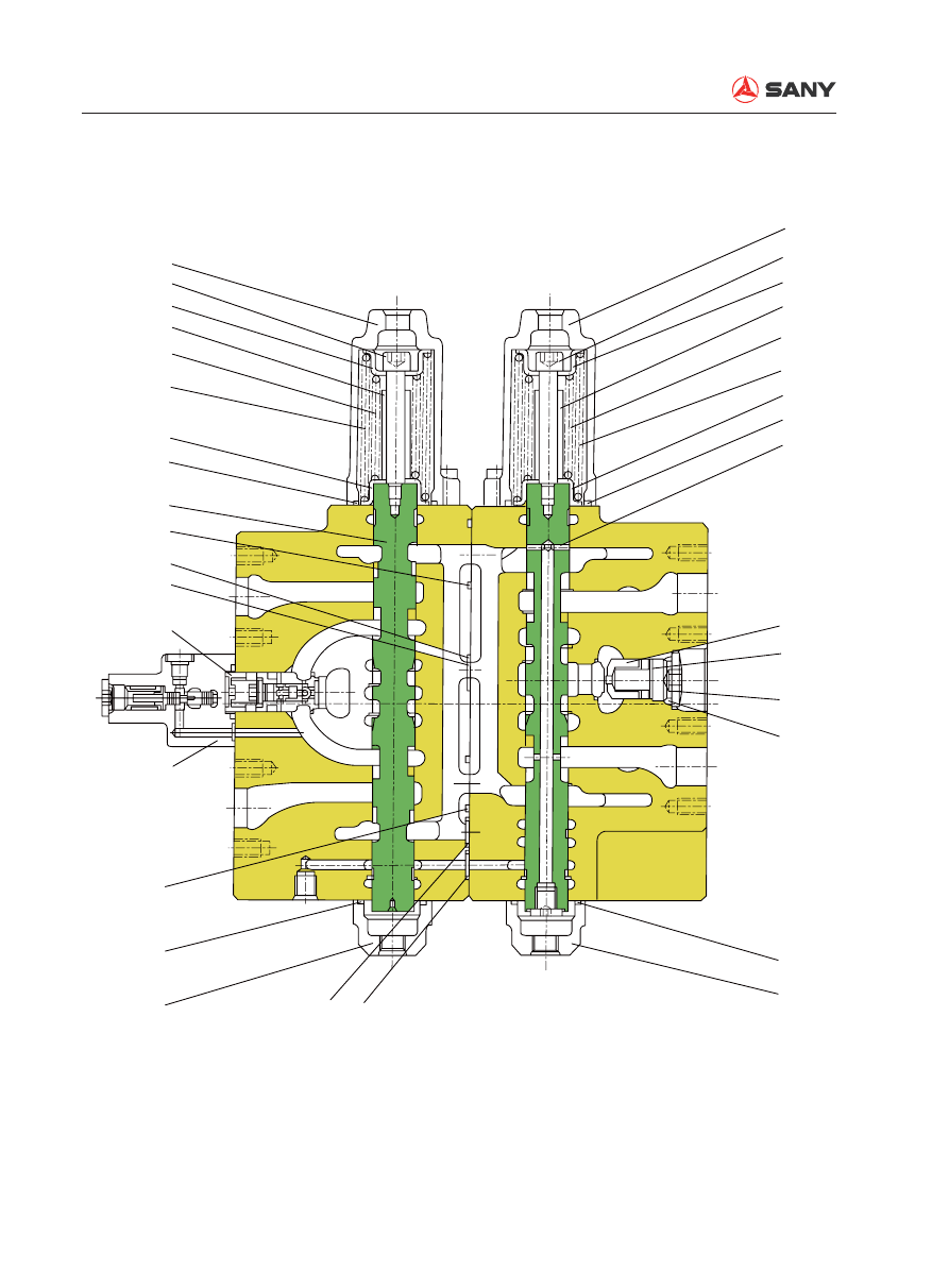
Section D-D (Swing, travel left)

Structure and Function

SY215C

LC

4-77

XAb2

XBb1

202

336
332

339
327

326

332

261

161

511

521

551

561
165
307

163

551
561

311

Xb2

CCb

Dr1

161

261

332

320

329
339

332
336
202

Psp

163

XAb1

BbR

158

204

602

264

303

Bb

561

551

LCb

521

511

513

561

552

523

PbL

CRb

158

201
336
332

335
321
320
602
332
261

L

BOOM2

BOOM1

View E-E

SWING
PRIORITY

View L-L

ZX225-1102040

L

Section E-E, L-L (Boom 1, boom 2)

Structure and Function

SY215C

LC

4-78

(XBo)

259

164

201

336

332
335
321

320

332

261

604

163

209

971×4

971×4

165
309
163
163

511

521

551

561

163
165

209 

163

264

604
204

164

154

(Bo)

LCo

(Ao)

BoR

(XAo)

PCk

XBk

BkR

258

ZX225-1102041

561

211

206

264

602

Bk

561

551

521

511

Ak

AkR

304

261

332

602

320

321

335

332

336

201

OPTION

BUCKET

View F-F

Section F-F (Option, bucket)

Structure and Function

SY215C

LC

4-79

XBa1

XBa2

Dr3

AR

201
336

332
335
321

320
257

332

261

163
165
162
152

152

165
162

302

511

521

551

561

163

165

163

264

602

205

BaR

XAa1

XAa2

204

ZX225-1102042

264

511

521

561

551

256

R2

LCAT2

251

552

561

523

513

158

CRa

L

L

306

261

332

320

321

335

332

336

201

View G-G

Section G-G (Arm 1, arm 2)

Structure and Function

SY215C

LC

4-80

612 169 162 152 158 154 164 152

152

162 162

164 154 158152 162 164 154 169 612

162 152

PCV2

XBp2

203 333 331 372 373 337 331 262

310

165

165

310

163 262 331 337 373 372 331333 203

ZX225-1102043

(XBp1)

PCV1

View H-H

Section H-H (Bypass cut 1, bypass cut 2)

Structure and Function

SY215C

LC

4-81

Mounting 

torque (N·m)

NO.

Part name

Q’ty

Mounting 

torque (N·m)

NO.

Part name

Q’ty

101

BLOCK, valve A

1

308

SPOOL ASS’Y, travel 

straight

 1

102

BLOCK, valve B

1

309

SPOOL, option

1

13~17

151

PLUG

3

310

SPOOL, bypass cut

2

34~39

152

PLUG

7

311

SPOOL, swing priority

1

220~250

153

PLUG

3

320

SPRING

9

69~78

154

PLUG

6

321

SPRING

8

7.4~9.8

156

PLUG, ori

fi

 ce

3

322

SPRING

1

7.5~10

158

PLUG

5

323

SPRING

1

10~14

159

PLUG

3

326

SPRING

1

161

O-RING

3

327

SPRING

1

162

O-RING

7

329

SPRING

1

163

O-RING

21

331

SPRING SEAT

4

164

O-RING

7

332

SPRING SEAT

22

165

O-RING

14

16~18

333

FLANGE SOCKET

2

166

O-RING

1

335

STOPPER

9

168

O-RING

3

16~18

336

FLANGE SOCKET

11

169

O-RING

2

337

STOPPER

2

201

COVER, spring

9

339

STOPPER

2

202

COVER, spring

2

372

SPRING

2

203

COVER, spring

2

373

SPRING

2

204

COVER, spool

7

511

VALVE, cone

8

205

COVER, spool

1

512

VALVE, cone

2

206

COVER, spool

1

513

VALVE, cone

2

209

FLANGE

2

514

VALVE, cone

2

210

PLATE

1

521

SPRING

10

211

PISTON

1

522

SPRING

2

49~65

251

VALVE, logic control

2

523

SPRING

2

9.8~14

252

OPTION ASS’Y, lock 

valve

2

541

BALL

1

254 VALVE GP, swing logic

1

542

SPRING SEAT

1

256 VALVE GP, arm 2 logic

1

543

SPRING

1

69~78

257

CHECK VALVE ASS’Y, 

arm regeneration

1

25~29

550

PLUG

1

258

PLUG

1

230~260

551

PLUG

11

259

PLUG

1

230~260

552

PLUG

2

261

O-RING

11

130~150

553

PLUG

2

Structure and Function

SY215C

LC

4-82

Mounting 

torque (N·m)

NO.

Part name

Q’ty

Mounting 

torque (N·m)

NO.

Part name

Q’ty

262

O-RING

2

561

O-RING

17

264

O-RING

9

562

O-RING

2

25~34

273

SCREW, hex, S,H,C

44

69~78

601

VALVE, main relief

1

98~120

274

SCREW, hex, S,H,C

4

69~78

602

VALVE, port relief

6

301

SPOOL, travel

2

120~140

604

VALVE, port relief

2

302

SPOOL ASS’Y, arm 1

1

69~78

612

PLUG

2

303 SPOOL ASS’Y, boom 1

1

49~65

971

SCREW, hex, S,H,C

8

304

SPOOL, bucket

1

140~180

975

SCREW, hex, S,H,C

10

305

SPOOL, swing

1

977

PLATE name

1

306

SPOOL, arm 2

1

978

PIN

2

307

SPOOL, boom 2

1

Structure and Function

SY215C

LC

4-83

4.6  

Hydraulic System, Part 3

4.6.1  

Swing motor

ZX215-1002081

L

PB

PA

IP

M

DB

SH

PG

B

A

1

2

A: Main oil port
B: Main oil port
M: Oil complement port
PA: Pressure detection port
PB: Pressure detection port
DB: Lubricating port
PG: Brake release port
SH: Brake direction port
L: Oil level stick
IP: Gear oil feed port

Type

M5×180CHB-12A-51A/260

Theoretical displacement 169.4 cm³/rev

Safety valve set pressure 25.5 MPa {255 Kg/cm³}

Rated engine speed

2000 rpm

Brake release pressure

2.7 MPa {27 Kg/cm³}

Specifi cations

1. Safety valve
2. Reverse prevention valve

Structure and Function

SY215C

LC

4-84

ZX215-1002082

A-A

12

13

8

1

5

4

3

11

2

9

6

7

10

A

A

1- Spacer
2- Casing
3- Disc
4- Brake spring
5- Shell

6-  Check valve spring
7- Check valve
8-  Oil distribution plate
9- Cylinder 
10- Brake piston

11- Plate
12- Piston
13- Drive shaft

Structure and Function

SY215C

LC

4-85

4.6.2  

Swing holding brake


Port PG is connected with the pilot gear pump directly, and a pressure of 3.9MPa is main-
tained. 

ZX215-1002083

a

5

1

6

7

M

PX

PG

SH

Pump

Main valve


Port SH is connected with port PX of the main valve. Once any movement other than travel 
is applied on the main valve, pressure will be generated at port PX, and port PG is intercon-
nected with chamber a beneath piston 7. The pressurized oil compresses brake spring (1) 
and pushes the brake piston up. Disc (5) is separated from plate (6), releasing the brake.

ZX215-1002084

a

5

1

6

7

M

PX

PG

SH

Pump

Main valve


Otherwise, no pressure is generated at port PX, and port PG is shut off from chamber a be-
neath piston (7). Brake piston (7) is pushed down by brake spring (1). Disc (5) and plate (6) 
are pushed together, and the brake is applied.

Structure and Function

SY215C

LC

4-86

4.6.3  Relief valve portion

Structure


The relief valve portion consists of relief 
valves (1) and (2), check valves (3) and (4).

Function


When the machine is in the swing holding 
mode, control valve (5) closes the motor 
outlet circuit, but the motor rotation contin-
ues due to inertial force. The motor output, 
therefore, is abnormally increased, result-
ing in motor damage.


In order to avoid the motor damage, the 
relief valve relieves the abnormally high 
pressure to port (M) from the motor outlet 
side (high-pressure side) of the motor.

Structure and Function

SY215C

LC

4-87

Operation

1.  When swing begins (suppose pressur-

ized oil enters Port A)


When the swing control lever is operated 
for right swing, pressurized oil from the 
pump is supplied to port (A) via control 
valve (5).


The pressure on port (A) rises, the starting 
torque is generated in the motor, and the 
motor is activated.


The pressurized oil from the outlet port of 
the motor passes from port (B) through the 
control valve (5) and returns to the tank.

2.  When swing stops


When the swing control lever is neutral-
ized, the supply of pressurized oil from the 
pump to port (A) is cut off.


The pressurized oil from the motor outlet 
can't return to the tank since the return cir-
cuit to the tank is closed from control valve 
(5). Thus, pressure at port (B) rises.


Swing resistance is generated on the mo-
tor and hence the brake starts working.


Pressurized oil will be relieved when the 
pressure on port (B) rises to the set pres-
sure of relief valve (2).


A high braking torque is applied on the mo-
tor, thereby stopping the motor.


When relief valve (2) is being actuated, the 
relieved pressurized oil and the pressur-
ized oil from port (M) are fed to port (B) via 
check valve (4).


Above prevents cavitation on port (B).

ZX215-1002085

From port M

1

2

3

C

A

B

5

4

ZX215-1002086

1

2

3

C

5

4

A

B

From port M

Structure and Function

SY215C

LC

4-88

1- Valve body
2-  Spool (A side)
3-  Spring (A side) 
4- Plug

5-  Spool (B side) 
6-  Spring (B side) 
7- Plug

4.6.4  

Reverse prevention valve

4.6.4.1 Operation drawing

ZX215-1002087

T2

B

T1

A

Swing controller

1

2

3

7

6

5

4

Swing
motor

B

A

T

Structure and Function

SY215C

LC

4-89

4.6.4.2  Explanatory drawing of effects

Outline


Inertia of the swing body, the backlash and 
rigidity of the machinery system, and the 
compression of the hydraulic oil all may 
cause the machine to shake during swing 
operation. The reverse prevention valve is 
designed to reduce this effect. The valve 
contributes in preventing collapsing of load 
when the swing is stopped and also con-
tributes in reducing cycle time (enhances 
the positioning performance, enabling you 
to proceed to the next work quicker than 
ever).

ZX215-1002088

:

With reversal prevention valve

:Without reversal prevention valve

Reversal pressure

Containment pressure

Time

Start

Brake

Motor speed

Pressure MB

Pressure MA

Reversal pressure

Reversal

1st reversal

2nd reversal

ZX215-1002089

T

B

A

T

D1

c

d Notch

b f

e

D4 a D3

D2

Structure and Function

SY215C

LC

4-90

Operation

3.  When port (B) brake pressure is gener-

ated


Pressure (MB) is conducted to chamber (d) 
via the notch. The pressure compresses 
spring (6) by use of the difference in areas 
of circles (D1 > D2) of spool (5) and moves  
spring (6) to the left side. Port (B) and 
chamber (e) will be interconnected. Since 
pressure (A) is lower than the set pressure 
of spring (3), spool (2) does not move and 
the pressurized oil is stopped by spool (2). 
Thus the braking force is ensured.

4.  When motor is stopped


The motor rotation is reversed by the clos-
ing pressure generated at port (B). (1st 
time: reverse rotation) Reversing pressure 
is generated on port (A). Pressure (A) is 
conducted to chamber (a), and spool (2) 
moves spring (3) to the right side, and A 
and B is interconnected. At this time, b 
is interconnected with f via the orifice on 
spool (5), and reversing pressure on port A 
is bypassed to port T, preventing the sec-
ond reverse rotation. 

ZX215-1002090

D4

D2

c

d

b f

e

D4 a D3

D1

T

B

A

T

Notch

ZX215-1002091

2

b

d

3

a

f

5

T

A

B

T

Structure and Function

SY215C

LC

4-91

4.6.5  Center swivel joint

ZX215-1002092

F1

G

Z

Z

F

A

C

H

H

H-H

D

B

A1

C1

B1

D1

13

12

11

10

9

8

7

6

5

4

3

2

1

G1


Content      ..     9      10      11      12     ..