SANY Crawler Hydraulic Excavator SY215CLC (CUMMINS QSB6.7 engine). Shop Manual - page 9
 

  Index      Manuals     SANY Crawler Hydraulic Excavator SY215CLC (CUMMINS QSB6.7 engine). Shop Manual


Search            copyright infringement  


Content      ..     7      8      9      10     ..


SANY Crawler Hydraulic Excavator SY215CLC (CUMMINS QSB6.7 engine). Shop Manual - page 9


Structure and Function

SY215C

LC

4-44

4.5  

Hydraulic System, Part 2

4.5.1  

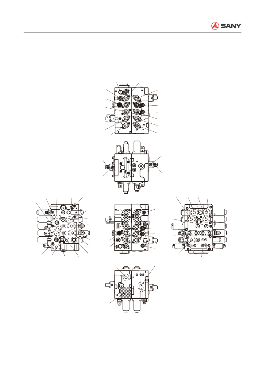
Control valve

ZX225-1102009

Dr6

Pns

PnA2

Dr7

Dr3

XBp2

XAa1

(XAo)

BaR

BoR

Dr2

XAs

Psp

XBtr

XBtr

(PTa)

XBtL

BbR

BkR

XAb1

XAa2

P2

R1

R1

P1

SWING PRIORITY

Ba(Head)

(Bo)

Bs

Btr

Atr

Dr1

As

(Ao)

PCV1

Dr3

ARM1

OPTION

XAb2

XBs

SWING

XAtr

BOOM2

(XBp1)

(BYPASS CUT 1)

XBa1

(XBo)

TRAVEL RIGHT

TRAVEL STRAIGHT

TRAVEL LEFT

BOOM1

BUCKET

ARM2

XBa2

XAk

XBb1

XAtL

Pz

AtL

PbL

Bk(Rod)

R2

Bb(Rod)

PCk

XBk

Ab(Head)

Ak(Head)

Aa(Rod)

PaL

BtL

Py

MR

DR3

AoR

AkR

AbR

AaR

PG

PX

Structure and Function

SY215C

LC

4-45

XAtr  : R. travel (reverse) pilot port
XBtr  : R. travel (forward) pilot port
(XAo)  : (Option pilot port)
(XBo)  : (Option pilot port)
XAk 

: Bucket (DIG) pilot port

XBk 

: Bucket (DUMP) pilot port

XAb1  : Boom 1 (UP) pilot port
XBb1  : Boom 2 (DOWN) pilot port
XAa2  : Arm 2 (OUT) pilot port
XBa2  : Arm 2 (IN) pilot port
XAtL  : L. travel (reverse) pilot port
XBtL  : L. travel (forward) pilot port
XAs 

: Swing (left) pilot port

XBs 

: Swing (right) pilot port

XAa1  : Arm 1 (OUT) pilot port
XBa1  : Arm 1 (IN) pilot port
Dr1 

: Drain port

Px 

: Work equipment signal port

Py 

: Travel signal port

Pz 

: Main relief valve boosting pressure

PG 

: Pilot pressure resource port

Pns 

: Swing logic control valve pilot port

PCK  : Bucket (DIG) stroke limit pilot port
PnA2  : Arm 2 logic control valve pilot port
Dr2 

: Drain port

Dr3 

: Drain port

Dr6 

: Drain port

Dr7 

: Drain port

Pal 

: Lock valve pilot port (arm rod end)

PbL 

: Lock valve pilot port (boom head end)

(XBp1) : Bypass cut spool pilot port (P1 side)
XBp2  : Bypass cut spool pilot port (P2 side)

XAb2  : Boom con

fl

 uence (UP) pilot port pres-

sure
Psp 

: Swing priority pilot port

R1 

: Return port

R2 

: Oil feed port

Atr 

: R. travel motor port (reverse)

Btr 

: R. travel motor port (forward)

(Ao) : 

Option

(Bo) : 

Option

Ak 

: Bucket cylinder head end port (DIG)

Bk 

: Bucket cylinder rod end port (DUMP)

Ab 

: Boom cylinder head end port (UP)

Bb 

: Boom cylinder rod end port (DOWN)

AtL 

: L. travel motor port (reverse)

BtL 

: L. travel motor port (forward)

As 

: Swing motor port (left swing)

Bs 

: Swing motor port (right swing)

Aa 

: Arm cylinder rod end port (OUT)

Ba 

: Arm cylinder head end port (IN)

P1 

: Pump port (P1 side)

P2 

: Pump port (P2 side)

MR 

: Main relief valve

AR 

: Arm regeneration check valve

AbR  : Port relief valve
BbR  : Port relief valve
AkR  : Port relief valve
BkR  : Port relief valve
AoR  : Port relief valve
BoR  : Port relief valve
AaR  : Port relief valve
BaR  : Port relief valve

Structure and Function

SY215C

LC

4-46

Item

Specifi cation

Model

KMX15RB

Standard 

fl

 ow rate (equivalent to one pump)

220L/min

Maximum pressure

When main relief valve is normal

34.3MPa

When main relief valve is boosting

37.3MPa

Maximum pressure

When port relief valve is normal

39.2MPa

Working oil temperature

-20~90°C

Drained oil maximum pressure

0.3MPa

Specifi cations

Structure and Function

SY215C

LC

4-47

4.5.2  

Hydraulic circuit diagram (with bucket confl uence function)

XBtr

XAtr

Atr
Btr

Dr2
Dr6

XBs

XAs

As

Bs

Pns

Psp

XAb2

(XBo)

(XAo)

(Ao)
(Bo)

Dr3

AR

XAa1

XBa1

(HEAD)

Ba

BaR

(XBp1)

XBp2

P2

R1

(P3)

(P0)

CP1

LCs

4-

Φ

2.1

2-

Φ

1.0

2-

Φ

2.0

CCb

LCo

AoR

BoR

LCa

CCk

CCo

(P5)

HVa

AaR

LCAP2

LCAT2

AkR

BkR

LCk

HVb

AbR

BbR

LCb

C2

CPG

(PTa)

P1

PG

MR

CMR2

CMR1

d1

Φ

0.7

d2

Φ

0.7

d3

Φ

0.7

Pz

Px

Py

XBtl

XAtl

Btl

Atl

Dr1

XBb1

XAb1

Bb
(ROD)

Ab
(HEAD)

PbL

PCk

XBk

XAk

(ROD)

Bk

Ak
(HEAD)

PnA2

Dr7

XBa2

XAa2

Aa
(ROD)

PaL

R2

ZX225-1102010

TRAVEL R

SWING

SWING
PRIORITY

BOOM2

ARM1

BYPASS
CUT

OPTION

ARM2

BUCKET

BOOM1

TRAVEL L

TRAVEL
STRAIGHT

Structure and Function

SY215C

LC

4-48

4.5.3 Operating principle

[Main circuit]

When all the spools are in neutral position, 
working oil supplied from the hydraulic pump 
(Front) flows in through pump port P1 and is 
introduced into the main passage (1). It pass-
es the neutral bypass (2) (neutral M-shaped 
spool mechanism) of the spools of straight 
travel (308), L. travel (301), boom 1 (303), 
bucket (304) and arm 2 (306), and 

fl

 ows back 

into the working oil tank via return port (R1). 

Working oil supplied from the hydraulic pump 
(Rear) flows in through pump port P2 and is 
introduced into the main passage (3). It pass-
es the neutral bypass (2) (neutral M-shaped 
spool mechanism) of the spools of  R travel 
(301), swing (305), boom confluence (boom 
2: 307), option (309), arm 1 (302), and flows 
back into the working oil tank via return port 
(R1). 

4.5.3.1  When spool is in neutral position

Structure and Function

SY215C

LC

4-49

(PTa)

XBtL

XAbL

PCk

X8k

XAa2

R1

CCk

CCo

XBa2

XBb1

XAtL

(1)

(2)

(2)

(3)

XAk

XAtr

XBs

XAb2

(XBo)

XBa1

(XBp1)

ZX225-1102011

P2

(P3)

Psp

XAs

XBtr

XBp2

XAa1

(XAo)

Structure and Function

SY215C

LC

4-50

XAtr

Atr

Btr

XBtr

ZX225-1102012

Travel motor

4.5.3.2 Travel

[Pilot circuit]


When the left or right travel spool is 
switched, the side bypass circuit is closed 
and pressure at port Py (travel signal port) 
rises. 

[Main circuit]


When pressure at pilot port XBtL for left 
travel spool (301) rises, neutral bypass (2) 
at boom 1 side is closed, and working oil 
supplied from the hydraulic pump (front) is 
introduced into the left travel motor via port 
Btl. 


Likewise, when pressure at port XBtr for 
the right travel spool (301) rises, neutral 
bypass (2) at arm 1 side is closed, and 
working oil supplied from the hydraulic 
pump (rear) is introduced into the right 
travel motor via port Btr.


On the other hand, return oil from the left 
and right travel motor passes the left (right) 
travel spool via port Atl (Atr), and returns to 
working oil tank via return port (R1). 


The principle is the same when travel on 
the opposite side is operated (when pres-
sure at pilot port XAtr and XAtl rises). 

Structure and Function

SY215C

LC

4-51

4.5.3.3 Arm

[Pilot circuit]


When the arm 2 spool (306) is switched, 
the side path is closed and pressure at port 
Px (work equipment signal port) rises. 

[Main circuit]


When arm OUT is operated, pilot pres-
sure oil is supplied into port XAa1 and port 
XAa2. When pilot pressure oil is applied at 
the two sides of port XAa1 and port XAa2, 
arm 1 spool and arm 2 spool are switched 
to the left as shown in the illustration. As 
a result, working oil from P2 is introduced 
into neutral bypass (2) via main passage 
(3). Neutral bypass is cut off by switching 
arm 1 spool (302). Therefore, working oil 
in the parallel passage pushes open the 
cone valve (511) of the check valve, and 

fl

 ows into the arm 1 spool (302) via the U 

passage. Then, it flows into the periphery 
of arm 1 spool (302) and arm 2 spool (306) 

and is supplied into the arm cylinder rod 
end (R) via port As. 


On the other hand, working oil from port 
P1 is introduced into neutral bypass (2) via 
main passage (1). Neutral bypass is cut off 
by switching the arm 2 spool (306). There-
fore, working oil in the parallel passage 
pushes open the logic cone valve (256-101) 
of the arm 2 logic valve GP, and working oil 
from neutral bypass pushes open the cone 
valve (511) of the check valve and flows 
into the arm 2 spool (306) via the U pas-
sage. Then, it merges with port As via the 
inner passage of arm 2 spool (306) and is 
supplied into the arm cylinder rod end (R).


Return oil from the arm cylinder head end 
(H) via port Ba 

fl

 ows into the tank circuit of 

arm 1 and arm 2, and returns to working oil 
tank via tank port (R1). 

(1) Arm OUT

Structure and Function

SY215C

LC

4-52

R

H

Aa

Ba

ZX225-1102013

511

511

XAa2

XAa1

256-101

Structure and Function

SY215C

LC

4-53

[Pilot circuit]


When the arm 2 spool (306) is switched, 
the side path is closed and pressure at 
port Px (work equipment signal port) rises. 
At the same time, pressure oil is supplied 
to port PaL and the release signal of lock 
valve option set (252) is sent out.

[Main circuit]


When arm In is operated, pilot pressure oil 
is supplied to port XBa1 and port XBa2. 
When pilot pressure oil is applied at the 
two sides of port XBa1 and port XBa2, 
arm 1 spool and arm 2 spool is switched to 
the left. As a result, working oil from P2 is 
introduced into the neutral bypass (2) via 
main passage (3). Neutral bypass is cut off 
by switching arm 1 spool (302). Therefore, 
working oil 

fl

 own into the parallel passage 

pushes open the cone valve (511) of the 
check valve and 

fl

 ows into the arm 1 spool 

(302) via the U passage. Then, it 

fl

 ows into 

the periphery of arm 1 spool (302) and is 
supplied into the arm cylinder head end (H) 
via port Ba. 


On the one hand, working oil from port P1 
is introduced into neutral bypass (2) via 
main passage (1). Neutral bypass is cut off 
by switching the arm 2 spool (306). There-
fore, working oil in the parallel passage 
pushes open the logic cone valve (256-101) 
of the arm 2 logic valve GP, and working oil 

from neutral bypass pushes open the cone 
valve (511) of the check valve and flows 
into the arm 2 spool (306) via the U pas-
sage. Then, it merges with port Ba via the 
inner passage of arm 2 spool (306) and is 
supplied into the arm cylinder head end (H).


On the other hand, pressure of the return 
oil from the arm cylinder rod end (R) rises 
under the weight the arm, and the return 
oil returns to port Aa. Working oil that re-
turns to port Aa 

fl

 ows into the inside of the 

valve spool via the holes on the periph-
ery of the arm 1 spool (302), and pushes 
open the cone valve (302-317) in the spool 
only under light load. It merges with port 
Ba through the holes on the spool. This is 
called the regeneration function of the arm. 


If the pressure at the arm cylinder head 
end and in the U passage rises, arm re-
generation check valve spool (257-211) 
switches to the left. And, at the same time, 
the back pressure of the cone valve (302-
317) in the spool is closed. Therefore, 
arm regeneration function is released and 
return oil from the arm cylinder rod end 
(R) 

fl

 ows into the spool via the hole (a) on 

the periphery of arm 1 spool (302). Then, 
it 

fl

 ows into arm regeneration check valve 

set (257) via hole (c) on the periphery of 
arm 1 spool (302), and returns to the work-
ing oil tank via tank port R1. 

(2) Arm IN

Structure and Function

SY215C

LC

4-54

H

Aa

XBa1

XBa2

(a)

(b)

ZX225-1102014

(302-317)

Ba

R

Arm weight


Light load

Structure and Function

SY215C

LC

4-55

R

H

Aa

XBa1

XBa2

(c)

(257-211)

(a)

Ba

ZX225-1102015

(302-317)


When pressure at arm cylinder head end (H) rises

Structure and Function

SY215C

LC

4-56

4.5.3.4 Boom

[Pilot circuit]


When the boom 1 spool (303) is switched, 
the side path is closed and pressure at port 
Px (work equipment signal port) rises. 

[Main circuit]


When boom UP is operated, pilot pressure 
oil is supplied into port XAb1 and boom 1 
spool (303) moves to the left. Working oil 
from port P1 is introduced into neutral by-
pass (2) via main passage (1). Neutral by-
pass is cut off by switching boom 1 spool 
(303). Therefore, working oil in the parallel 
passage pushes open the cone valve (511) 
of the check valve, and 

fl

 ows into the boom 

1 spool (303) via the U passage. Then, it 
flows into the periphery of boom 1 spool 
(303) and is supplied into the boom cylin-
der head end (H) via port Ab. 


At the same time, pilot pressure oil is also 
supplied to port XAb2 and boom 2 spool 
(307) moves to the right. Working oil from 
port P2 is introduced into neutral bypass. 
Neutral bypass is cut off by switching the 
boom 2 spool (307). Therefore, working 
oil in the parallel passage 

fl

 ows into boom 

2 spool (307) via the U passage. Then, it 
pushes open the cone valve (511) of the 
check valve and merges with port Ab and 
is supplied into the boom cylinder head 
end (H). This is called the boom conflu-
ence function.


On the other hand, return oil from the 
boom cylinder rod end (H) via port Bb 

fl

 ows 

into the periphery of boom 1 spool (303) 
and returns to the working oil tank via tank 
port (R1). 

(1) Boom UP

Structure and Function

SY215C

LC

4-57

H

Bb

R

511

XAb1

ZX225-1102016

XAb2

511

Ab

Structure and Function

SY215C

LC

4-58

H

Ab

511

R

Bb

XBb1

(a)

(b)

(303-317)

ZX225-1102017

[Pilot circuit]


When the boom 1 spool (303) is switched, 
the side path is closed and pressure at 
port Px (work equipment signal port) rises. 
At the same time, pressure oil is supplied 
to port PbL and the release signal of lock 
valve option set (252) is sent out.

[Main circuit]


When boom DOWN is operated, pilot pres-
sure oil is supplied to port XBb1. Boom 1 
spool (303) moves to the right. As a result, 
working oil from P1 is introduced into the 
neutral bypass (2) via main passage (1). 
Neutral bypass is cut off by switching boom 
1 spool (303). Therefore, working oil 

fl

 own 

into the parallel passage pushes open the 
cone valve (511) of the check valve and 

fl

 ows into the boom 1 spool (303) via the U 

passage. Then, it flows into the periphery 
of boom 1 spool (303) and is supplied into 
the boom cylinder rod end (R) via port Bb. 


On the other hand, return oil from the 
boom cylinder head end (H) passes the 
hole (a) and the periphery of boom 1 spool 
(303). 


Return oil pressure rises due to the self 
weight of the boom. Cone valve (303-317) 
in the spool is pushed to the right. Return 
oil 

fl

 ows to the outside of spool. The pres-

sure oil is supplied into the boom cylinder 
rod end (R) as the working oil for boom 
DOWN operation. This is called the boom 
regeneration function. Part of the oil that 

fl

 ows into the inside passage of the spool 

via hole (a) returns to the working oil tank 
via hole (b). 

(2) Boom DOWN

Structure and Function

SY215C

LC

4-59

Ak

Bk

Pck

XAk

ZX225-1102018

H

H

R

4.5.3.5 Bucket

[Pilot circuit]


When the bucket spool (304) is switched, 
the side path is closed and pressure at port 
Px (work equipment signal port) rises. At 
the same time, pressure oil is supplied at 
port XBp2. 

[Main circuit]


When bucket DIG is operated, pilot pres-
sure oil is supplied into port XAk and buck-
et spool (304) moves to the right. Working 
oil from port P1 is introduced into neutral 
bypass (2) via main passage (1). Neutral 
bypass is cut off by switching bucket spool 
(304). Therefore, working oil in the paral-
lel passage pushes open the cone valve 
(511) of the check valve, and flows into 
the bucket spool (304) via the U passage. 

Then, it 

fl

 ows into the periphery of bucket 

spool (304) and is supplied into the bucket 
cylinder head end (H) via port Ak. 


On the other hand, return oil from the buck-
et cylinder rod end (R) 

fl

 ows in via port Bk. 

Then, it flows to oil tank port (R1) via the 
spool periphery and returns to working oil 
tank.


When boom UP and bucket DIG are oper-
ated simultaneously, pilot pressure oil is 
supplied to port Pck. Therefore, the stroke 
of bucket spool is not limited at stroke end, 
but on any position halfway.  As a result, 
bucket cylinder passage is throttled and 
working oil flows into boom 1 spool (303) 
via bucket spool (304). In this way, boom 
UP operation takes precedence.

(1) Bucket DIG


Content      ..     7      8      9      10     ..