SANY Crawler Hydraulic Excavator SY215CLC (CUMMINS QSB6.7 engine). Shop Manual - page 8
 

  Index      Manuals     SANY Crawler Hydraulic Excavator SY215CLC (CUMMINS QSB6.7 engine). Shop Manual


Search            copyright infringement  


Content      ..     6      7      8      9     ..


SANY Crawler Hydraulic Excavator SY215CLC (CUMMINS QSB6.7 engine). Shop Manual - page 8


Structure and Function

SY215C

LC

4-28

4.4.3  

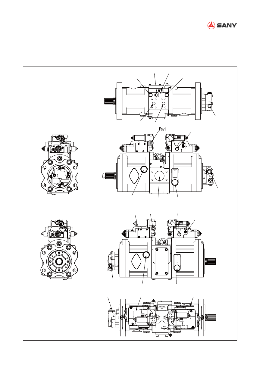
Hydraulic pump

Type: K3V112DTP1N9R  

ZX215-1002018

a1
{36N·m}

a2
{36N·m}

a5
{16N·m}

a4
{36N·m}

PH1

PH2

A1

A2

A3

4

1

2

3

5

B1

B3

Clockwise

Psv2

DR2{170N·m}

DR4{170N·m}

DR3{170N·m}

DR1{170N·m}

a3
{36N·m}

Structure and Function

SY215C

LC

4-29

a1: F. pump main pressure detection port

a2: R. pump main pressure detection port

a3: F. pump regulator pressure detection port

a4: Adjustor control pressure detection port

a5: Pilot gear pump output pressure detection 
port

PH1: F. pump pressure sensor assembly port

PH2: R. pump pressure sensor assembly port

A1: F. pump delivery port

A2: R. pump delivery port

A3: Pilot gear pump delivery port

Psv1: F. pump regulator control port

Psv2: R. pump regulator control port

Dr1: F. pump drain plug

Dr2: R. pump drain plug

Dr3: Air bleeder

Dr4: Drain plug

B1: Pump suction port

B3: Pilot gear pump oil suction port

1: Front pump

2: Rear pump

3: Pilot gear pump

4: Front pump regulator

5: Rear pump regulator

Outline


This pump consists of 2 variable capacity swash plate plunger pumps, 2 regulators, and 1 pi-
lot gear pump.

Structure and Function

SY215C

LC

4-30

1- Front shaft
2-  Min. delivery adjusting screw
3- Front casing
4- Swash plate
5- Slipper
6- Plunger
7- Cylinder block
8- Valve plate

9- End cover
10- Rear shaft
11- Rear casing
12- Gear pump
13- Piston
14-  Max. delivery adjusting screw
15- Gear shaft
16- Driving pin

ZX215-1002019

3

5

4

1

2

13

6

7

14

9

16

10

15

8

12

11

Structure and Function

SY215C

LC

4-31

Function


The  torque of the engine is transmitted 
to the pump shaft (1), and drives cylinder 
block (7) to rotate. At the same time, nine 
plungers (6) slide along the thrust plate (8). 
Plunger (6) moves back and forth inside 
cylinder block (7) and pressurized oil is 
sucked and discharged alternatively. 


It is possible to change the discharge 
amount by changing the swash plate an-
gle.

ZX215-1002020

18

1

5

A

4

18

17

6

B

13

7

8

Structure and Function

SY215C

LC

4-32

Structure


Cylinder block (7) is supported to shaft (1) 
by spline (17).       


Shaft (1) is supported by front and rear 
bearings (18).


Tip of plunger (6) is shaped as a concave 
ball and slipper (5) is caulked to it to form 
one unit.


Plunger (6) and slipper (5) constitute the 
spherical bearing.


Swash plate (4) has flat surface (A), and 
slipper (5) is always pressed against this 
surface while sliding in a circular move-
ment.


Swash plate (4) conducts high pressure oil 
to cylinder surface (B), and forms a static 
pressure bearing when it slides.


Plunger (6) carries out relative movement 
in the axial direction inside each cylinder 
chamber of cylinder block (7).


Cylinder block (7) seals the pressurized oil 
to thrust plate (8) and carries out relative 
rotation.


This surface is designed so that the oil 
pressure balance is maintained at a suit-
able level.


The oil inside the respective cylinder cham-
bers of cylinder block (7) is sucked in and 
discharged through thrust plate (8).

Structure and Function

SY215C

LC

4-33

Operation of pump


Cylinder block (7) rotates together with 
shaft (1), and slipper (5) slides on 

fl

 at sur-

face (A).


When this happens, swash plate (4) moves 
along cylindrical surface (B), so angle (a) 
between central line (X) of swash plate (4) 
and the axial direction of cylinder block (7) 
changes.


(a) is named the swash plate angle.


With central line (X) of swash plate (4) at 
a swash plate angle (a) in relation to the 
axial direction of cylinder block (7), 

fl

 at sur-

face (A) acts as a cam in relation to slipper 
(5).


In this way, plunger (6) slides on the in-
side of cylinder block (7), so a difference 
between volumes (E) and (F) is created 
inside cylinder block (7).


A single plunger sucks and discharges the 
oil by the amount (F) – (E).


As cylinder block (7) rotates and the vol-
ume of chamber (E) becomes smaller, the 
pressurized oil is discharged.


On the other hand, the volume of chamber 
(F) grows larger and, in this process, the 
oil is sucked.


As central line (X) of swash plate (4) over-
laps the axial direction of cylinder block (7) 
(swash plate angle (a) = 0), the difference 
between volumes (E) and (F) inside cylin-
der block (7)becomes 0.


Suction and discharging of pressurized 
oil is not carried out in this state. Namely 
pumping action is not performed. (In real-
ity, however, the swash plate angle is not 
set to 0)

ZX215-1002021

1

4

5

7

B

X

a

A

ZX215-1002022

4

5

6

7

E

X

a

F

A

ZX215-1002023

7

4

E

F

Structure and Function

SY215C

LC

4-34

Control of delivery


If swash plate angle (a) becomes larger, 
the difference between volumes (E) and 
(F) becomes larger and pump delivery (Q) 
increases.


Piston (13) is used for changing swash 
plate angle (a).


Piston (13) carries out linear alternating 
motion under the control of the  adjustor.


This linear motion is transmitted to swash 
plate (4) via drive pin (16). The sliding of  
the swash plate changes the swash plate 
angle and changes the discharge amount 
of the main pump. 

ZX215-1002024

13

4

a

16

F

E

Structure and Function

SY215C

LC

4-35

4.4.4  

Pilot pump

ZX215-1002025

710

435

433

700

434

355

354

310

351

732

311

312

309

307

308

434 850

466

725

435

361

353

307: Valve stem
308: Valve base
309: Retainer
310: Spring
311: Adjusting screw
312: Nut
351: Body
353: Gear shaft
354: Gear shaft
355: Filter element

361: Body
433: Screw
434: Screw
435: screw
466: Plug
700: Washer
710: O-ring
725: O-ring
732: O-ring
850: Washer

Function


The engine actuates the main pump and 
the drive shaft of the pilot pump through 
the transmission case, and drives the pilot 
pump through gear engagement. 

Structure and Function

SY215C

LC

4-36

4.4.5  

Regulator (KR3G-0E11-AV)

G-OE11-V

Type

s/n

Name plate and s/n

Tightening torque

(KDRDE5K)

P

SV

P

SV

a

a

Hydraulic schematic diagram

KDRDE5C-1

079

325

496

408

755 466

407

643

651

652

733

631

731

624

627

B

A

A-A

A

646

897

924

801

402

656

614

755

708

611

733

724

887

SKY5P

- 17 - S

Direction B

ZX225-1102002

418

415

496

601

543

756

545

541

Part No.

Thread size

Tightening torque

N•m

402, 407

408

415

418

466

496

614

801

M6

M8

M5

G1/4

G1/4

M10

NPTF1/16

12

29

6.9

16

8.8

36

29

Structure and Function

SY215C

LC

4-37

Category

Part No.

Part name

Q’ty

Remark

C

924

Hexagon socket head locating screw

1

/

897

Pin

1

/

887

Pin

1

D

801

Hexagon nut

1

JIS  B  1181  N-M10

D

756

O-ring

2

D

755

O-ring

2

D

733

O-ring

2

D

731

O-ring

1

D

724

O-ring

5

D

708

O-ring

1

/

656

Cover plate

1

/

652

Spool valve

1

/

651

Sleeve

1

/

646

Guide spring

1

/

643

Pilot plunger

1

/

631

Pf pilot sleeve

1

/

627

Adjusting wheel

1

/

624

Spring seat

1

/

614

Plug

1

/

611

Feedback lever

1

/

601

Casing

1

/

545

Ball

2

/

543

Stopper

2

/

541

Valve seat

2

C

496

Embedded plug

9

C

466

VIP plug

1

D

418

Hex socket head bolt

2

JIS  B  1176  M5-12

D

415

Hex socket head bolt

6

JIS  B  1176  M8-50

D

408

Hex socket head bolt

1

JIS  B  1176  M6-40

D

407

Hex socket head bolt

4

JIS  B  1176  M6-30

D

402

Hex socket head bolt

4

JIS  B  1176  M6-16

/

325

Valve body

1

B

079

Sol proportional reducing valve

1

B

Regulator assembly

1

B: 

Assembly obtainable at the dealers (individual parts not purchasable)

/: 

Individual components included in assemblies of category B

C: 

Parts obtainable at the dealers

D: 

Parts obtainable on the market

Structure and Function

SY215C

LC

4-38


The regulator controls the pump discharge 
amount according to the command signal 
pressure, keeping the driving power of the 
pump lower than the engine output. 


Pumps 1 and 2 are both equipped with a 
regulator. Key components of the regulator 
include a solenoid proportional pressure 
reducing valve (1), a positive 

fl

 ow regulator 

(2), a servo reversing valve (3) and a servo 
piston (4). The regulator opens and shuts 
the oil circuit of the servo piston (3) and 
changes the tilting angle of the hydraulic 
tank according to various command signal 
pressure so as to control the pump dis-
charge amount. 

Function

4.4.5.1  Control mechanism makeup

Current control


The inclination (output delivery amount) 
of the pump can be controlled freely by 
changing of the command current I flow-
ing into the solenoid proportional pressure 
reducing valve. This regulator applies posi-
tive 

fl

 ow control (positive control), through 

which output delivery amount Q changes 
according to the increase of command cur-
rent. Necessary current for corresponding 
operation can be input through this control 
mechanism. The pump only delivers nec-
essary oil amount and wastes no useless 
power. 

P

SV

a

1

2

3

4

ZX225-1102003

Structure and Function

SY215C

LC

4-39

4.4.5.2  Adjustment of the regulator

531: Inclination pin

532: Servo piston

548: Feedback pin

806: Retaining nut

808: Retaining nut

953: Adjusting screw

954: Adjusting screw


It is possible to adjust the maximum and 
minimum 

fl

 ow by the adjusting screws (953, 

954) in the pump block side. Flow control 
features can be adjusted with the hexagon 
socket head locating screw (924) on the 
regulator. 

ZX215-1002028

953

806

532

548 531

808

954

P

SV

KDRDE5C-1

924

SKY5P
- 17 - S

ZX225-1102004

Structure and Function

SY215C

LC

4-40

Maximum flow adjustment (pump block 
side)


Loosen the hexagon nut (808), and tighten 
(or loosen) hexagon socket head locating 
screw (954). No control features except the 
maximum 

fl

 ow changes. 

Minimum flow adjustment (pump block 
side)


Loosen the hexagon nut (806), and tighten 
(or loosen) the hexagon socket head locat-
ing screw (953). Though this action is the 
same as the adjustment of maximum 

fl

 ow 

and all the other control features do not 
change, power required under maximum 
output pressure (overflow) is likely to in-
crease if over-tightened. Be careful in this 
case. 

ZX215-1002033

Output flow Q

Command current I

ZX215-1002034

Output flow Q

Command current I

ZX215-1002037

Output flow Q

Command current I

Flow control feature adjustment


After hexagon nut (810) is loosened, tight-
en (or loosen) the hexagon socket head lo-
cating screw (924) to carry out adjustment. 
When the hexagon socket head locating 
screw (924) is being tightened, the control 
diagram (as shown) will move to the right. 

Structure and Function

SY215C

LC

4-41

4.4.5.3 Operation

Flow control


The output flow of the pump can be con-
trolled by the command current I, as 
shown. 

ZX215-1002030

Output flow Q

Command current I

Action of increasing fl ow rate


When command current I increases, the 
solenoid proportional pressure reducing 
valve secondary pressure P2 will increase, 
and the spool valve (652) will move the 
right with the help of the guide piston (643). 
When a relative balance between the right-
ward hydraulic force and the spring force 
of guide spring (646) is achieved, spool 
valve (652) stops moving. 


As spool valve (652) moves to the right, 
because port cl and tank port are intercon-
nected, pressure of the large diameter 
portion of the servo piston is released and 
servo piston (532) moves to the left via the 
output pressure P1 in the shall diameter 
portion. The inclination becomes larger. 


Since feedback lever (611) is integrated 
with the servo piston and valve sleeve  
(651), if servo piston (632) moves to the 
left, feedback lever swings with point A as 
the pivot. In this way, valve sleeve moves 
to the right. 


Through this movement, the opening por-
tion between the spool and the valve block 
is closed slowly. The servo piston stops 
moving when the opening portion is com-
pletely closed. 

P1

P1

A

Tilt angle large

808
954

643

079

652

651

627 646

801

924
611

532

806
953

ZX225-1102005

P

SV

a

ZX225-1102006

Structure and Function

SY215C

LC

4-42

Action of reducing fl ow rate


When command current I decreases, the 
solenoid proportional pressure reducing 
valve secondary pressure P2 will decrease, 
and guide piston (643) will move to the left. 
However, as spool valve (652) moves, out-
put pressure P1 is introduced into the large 
diameter chamber of the servo piston via 
the port cl. On the other hand, output pres-
sure P1 is introduced into the small diam-
eter chamber of the servo piston and servo 
piston moves to the right via are difference. 
The inclination becomes smaller. 


As servo piston (532) moves to the right, 
the feedback lever swings with point A as 
the pivot and the valve sleeve moves to the 
left. Through this movement, the opening 
portion between the spool and the valve 
block is slowly closed. The servo piston 
stops moving when the opening portion is 
completely closed. 

P1

P1

A

Tilt angle small

808
954

643

079

652

651

627 646

801
924
611

532

806
953

ZX225-1102007

P

SV

a

ZX225-1102008

Structure and Function

SY215C

LC

4-43

Adjustment value of the regulator

Type of regulator

KR3G-0E11-AV

Rotating speed (min

-1

)

2050

Adjustment of max. 

fl

 ow

Adjusting screw (954) screw-in (rotation)

+1/4

Flow rate change (L/min

-1

)

-5.9

Adjustment of min. 

fl

 ow

Adjusting screw (953) screw-in (rotation)

+1/4

Flow rate change (L/min

-1

)

+4.7


Content      ..     6      7      8      9     ..