SANY Crawler Hydraulic Excavator SY215CLC (CUMMINS QSB6.7 engine). Shop Manual - page 6
 

  Index      Manuals     SANY Crawler Hydraulic Excavator SY215CLC (CUMMINS QSB6.7 engine). Shop Manual


Search            copyright infringement  


Content      ..     4      5      6      7     ..


SANY Crawler Hydraulic Excavator SY215CLC (CUMMINS QSB6.7 engine). Shop Manual - page 6


Specifi cations

SY215C

LC

3-6

3.4  

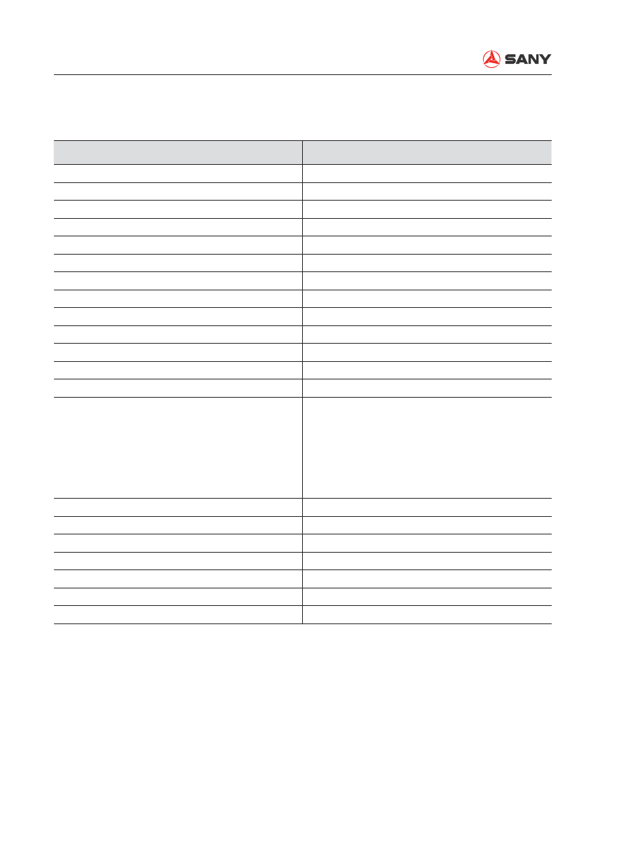
Weight Table

Note: 

This weight table is intended as a reference when handling or transporting the components.

Machine Model

SY215C

LC

Engine

485 kg (1,069 lb)

Radiator assembly

92 kg (203 lb)

Hydraulic tank assembly (without hydraulic oil)

148 kg (326 lb)

Fuel tank assembly (without fuel)

143 kg (315 lb)

Revolving frame

1764 kg (3,889 lb)

Operator cab

340 kg (750 lb)

Operator seat & control console

76 kg (168 lb)

Counterweight

3900 kg (8,598 lb)

Hydraulic pump

120 kg (265 lb)

Control valve

132 kg (291 lb)

Swing reducer assembly

289 kg (637 lb)

Final drive assembly

2×404 kg (891 lb)

Center swivel joint

48 kg (106 lb)

Track frame
Swing bearing
Idler
Tensioning device
Carrier roller
Track roller

3004 kg (6,623 lb)

293 kg (646 lb)

2×113 kg (249 lb)
2×115 kg (254 lb)

4×25.5 kg (56 lb)

18×40 kg (88 lb)

Boom assembly

1689 kg (3,724 lb)

Arm assembly

708 kg (1,561 lb)

Boom cylinder assembly

 2×206 kg (454 lb)

Arm cylinder assembly

262 kg (578 lb)

Bucket cylinder assembly

188 kg (414 lb)

Linkage

68 kg (150 lb)

Rocker

2×20 kg (44 lb)

Specifi cations

SY215C

LC

3-7

3.5  Fuel and Coolant

Reservoir

Fluid 

type

Ambient temperature

   -22           -4           14          32          50          68           86         104       122°F  
   -30          -20         -10           0           10          20           30          40          50°C

Engine oil pan

Engine 

oil

SAE 30

SAE 10W

SAE 10W-30

SAE 15W-40

Carrier roller

Idler

SAE 30

Track roller

Swing mechanism

Gear oil

Travel mechanism

Hydraulic sys-

tem

Engine 

oil

SAE 10W

SAE 10W-30

SAE 15W-40

Hydraulic 

oil

L-HV32 Low-temp, wear-resistant hydro oil

L-HM46 Wear-resistant hydro oil

L-HM68 Wear-resistant hydro oil

Fuel tank

Diesel 

fuel

ASTM D 975 No.2

GB252 Super-20 Die-

sel fuel

GB252 Super-35 Diesel fuel

Grease 

fi

 tting

Grease  

NLGI No.2

Cooling system Coolant

Add anti-freeze

Specifi cations

SY215C

LC

3-8


Machine oil above API CF-4 (no lower than 
APC CD) is recommended. 


Gear oil GL-5 is recommended.


Obtain genuine oil from Sany Heavy Ma-
chine or its authorized dealers. 

Specifi cations

SY215C

LC

3-9

3.6  

Engine Performance Curve

Cummins QSB6.7-C155

Testing condition:

1)  100kPa  {29.61 in Hg} barometric pressure, 91m {300 ft} attitude and 25°C {77°F}] inlet air 

temperature.

2)  Alternator and fan not included.

Specifi cations

SY215C

LC

3-10

Torque

600

450

400

350

300

160

140

120

100

80

60

40

0.45

0.40

0.35

0.30

0.25

800

1000

1200

1400

1600

1800

2000

200

250

40

60

80

100

550

500

450

To

rque (N·m)

Power (kW)

Fuel Consumption (g/kW·hr)

Fuel Consumption (lb/hp·hr)

Power (hp)

To

rque (lb·ft)

Engine speed (RPM)

Fuel consumption

Power output

Structure and Function

Structure and Function

SY215C

LC

4-1

4  Structure and Function

4.1  Engine and Cooling System .................................................................................... 4-3

4.2 Power Train.............................................................................................................. 4-5

4.3  Undercarriage and Frame...................................................................................... 4-13

4.4  Hydraulic System, Part 1 ....................................................................................... 4-24

4.5  Hydraulic System, Part 2 ....................................................................................... 4-44

4.6  Hydraulic System, Part 3 ....................................................................................... 4-83

4.7  Air Conditioning System....................................................................................... 4-132

4.8 Engine Control ..................................................................................................... 4-166

4.9  Electrical Control System..................................................................................... 4-172

4.10 Monitoring System ............................................................................................. 4-203

Structure and Function

SY215C

LC

4-2

WARNING

Always read the Safety section of this man-
ual before attempting to operate or service 
this equipment. Failure to do so could re-
sult in machine damage, personnel injury 
or death.

Structure and Function

SY215C

LC

4-3

ZX215-1002001

6

7

1

3

5

4

2

1- Fan
2-  Front engine mount
3- Fuel 

fi

 lter

4- Start motor
5-  Rubber damper assembly
6-  Rear engine mount
7- Muf

fl

 er

Specifi cation

Oil capacity: 22 L

4.1  Engine and Cooling System

4 STRUCTURE AND FUNCTION

4.1.1 Engine-related parts

Structure and Function

SY215C

LC

4-4

4.1.2  Radiator and intercooler

ZX215-1002002

1

2

3

4

5

6

7

8

9

10

1- Reservoir 
2- Radiator assembly
3-  Radiator inlet hose
4-  Radiator outlet hose
5-  Inlet air pipe
6-  Outlet air pipe
7- Intercooler
8- Guard net
9- Guard 
10- Radiator cap

Specifi cations

Radiator assembly: ME444275

Aluminum pipe, belt-type radiator

Inter-cooling, oil radiation/water radiation se-
ries connection type.

Reservoir capacity: 11.5L 

Structure and Function

SY215C

LC

4-5

4.2 Power Train

4.2.1  Power transmission system 

ZX215-1002003

2

1

3

4

5

6

7

8

9

10

1-  Swing motor (

M5X130CHB-12A-51A/260-169

)

2-  Swing reducer (

RG14D20A5

)

3- Swing bearing
4- Idler
5-  Center swivel joint

6- Accumulator
7-  Control valve (

KMX15RB

)

8-  Final drive AS (

GM35VL-E-75/130-3

)

9- Hydraulic pump(

K3V112DTP1N9R

)

10- Engine (

QSB6.7-C155

)

Structure and Function

SY215C

LC

4-6

4.2.2  

Final drive AS (KYB)

ZX215-1002004

205±10 N·m

73±3.6 N·m

59±4.9 N·m

157±8 N·m

1

2

3

4

5

6

7

8

9

10

11

12

16

19

17

20

18

ZX215-1002005

13

14

15

Structure and Function

SY215C

LC

4-7

1- Cylinder GP
2- Shaft
3-  Gear hub (No. of teeth: 85) 
4-  No. 2 planetary carrier
5-  No. 1 planetary carrier
6-  No. 1 planetary gear (No. of teeth: 36) 
7-  No. 1 sun gear (No. of teeth: 12) 
8- End cover

9-  No. 2 sun gear (No. of teeth: 19) 
10-  No. 2 planetary gear (No. of teeth: 36) 
11-    Seal ring
12- Travel motor
13- Fill port
14- Level port
15- Drain port

Specifi cations

Reduction ratio:

( (12+85) /12) × ( (19+85) /19) ) -1= 43.246

No. Check 

item

Criteria

Remedy

Standard clearance

Clearance limit

16

Backlash between No. 2 sun gear 
and No.2 planetary gear

0.13 – 0.47

1.00

Replace

17

Backlash between No. 1 planetary 
gear and gear hub

0.17 – 0.57

1.10

Replace

18

Backlash between No. 1 sun gear 
and No.1 planetary gear

0.14 – 0.46

1.00

19

Backlash between No. 2 planetary 
gear and gear hub

0.16 – 0.56

1.10

20

Backlash between No. 1 planetary 
carrier and No. 2 sun gear

0.38 – 0.66

1.00

Structure and Function

SY215C

LC

4-8

4.2.3  Final drive AS (Nabtesco)

ZX215-1002006

102 ±16 Nm

6

5

±20 Nm

7
8

9

98

11

12

10

709 ±108 Nm

2

1

±20 Nm

98

±2.5 Nm

12

3

4

ZX225-1102047

13

14

15

OIL

IN

DRAIN

LEVEL

Structure and Function

SY215C

LC

4-9

1- Plunger GP
2- Crankshaft
3- Gear hub
4- Roller bearing
5-  RV drive gear A
6-  RV drive gear B
7-  No. 1 planetary gear (42)
8-  No. 1 sun gear (18)

9- Shaft coupling
10- Retainer
11-  Motor output shaft
12- Travel motor
13- Fill port
14- Level port
15- Drain port

Specifi cations

Reduction ratio: 60

Structure and Function

SY215C

LC

4-10

4.2.4  

Swing machinery

ZX215-1002007

1

2

3

4

5

6

7

59~74 Nm

8

9

21

22

10

23
24

11

12

26

25

13

27

14

15

16

17

18

28

19

20

Structure and Function

SY215C

LC

4-11

No. Check 

item

Criteria

Remedy

Standard clearance

Clearance limit

21

Backlash between swing motor shaft 
and No. 1 sun gear

0.18 – 0.28

Replace

22

Backlash between No. 1 sun gear 
and No.1 planetary gear

0.16 – 0.50

1.00

Replace

23

Backlash between No. 1 planetary 
gear and ring gear 

0.18 – 0.59

1.10

24

Backlash between No. 1 planetary 
carrier and No. 2 sun gear

0.39 – 0.71

1.20

25

Backlash between No. 2 sun gear 
and No.2 planetary gear

0.16 – 0.50

0.90

26

Backlash between No. 2 planetary 
gear and ring gear 

0.18 – 0.59

1.00

27

Backlash between No. 2 planetary 
carrier and swing pinion

0.07 – 0.23

28

Backlash between swing pinion and 
swing bearing

0.22 – 1.32

2.00

Specifi cations

Reduction ratio: 

(14+25) /14× (16+25) /14= 20.04

1- Plug
2- Oil seal
3- Self-aligning bearing
4-  Ring gear (No. of teeth:52) 
5-  No. 2 planetary carrier
6-  No. 1 planetary carrier
7-  No. 2 sun gear (No. of teeth: 16) 
8-  No. 1 sun gear (No. of teeth:14) 
9- Swing motor
10-  No. 1 planetary gear (No. of teeth:18) 

11-  No. 2 planetary gear GP
12-  No. 2 planetary gear (No. of teeth:17) 
13- Spring pin
14-  Swing reducer screw plug
15- Grease 

fi

 tting

16- Self-aligning bearing
17- Bearing sealing
18- Swing pinion
19- Dipstick
20- Oil 

fi

 lling pipe


Content      ..     4      5      6      7     ..