SANY SRT45 Off-Highway Truck. Safety,Operation and Maintenance Manual (2014) - page 3
8.6.39 Maintenance inspection form for 4050hrs
8-115
8.6.40 Maintenance inspection form for 4200hrs
8-117
8.6.41 Maintenance inspection form for 6000hrs
8-119
8.6.42 Maintenance inspection form for 10000hrs
8-125
9 TECHNICAL DATA
9-1
D
Controls and Operating
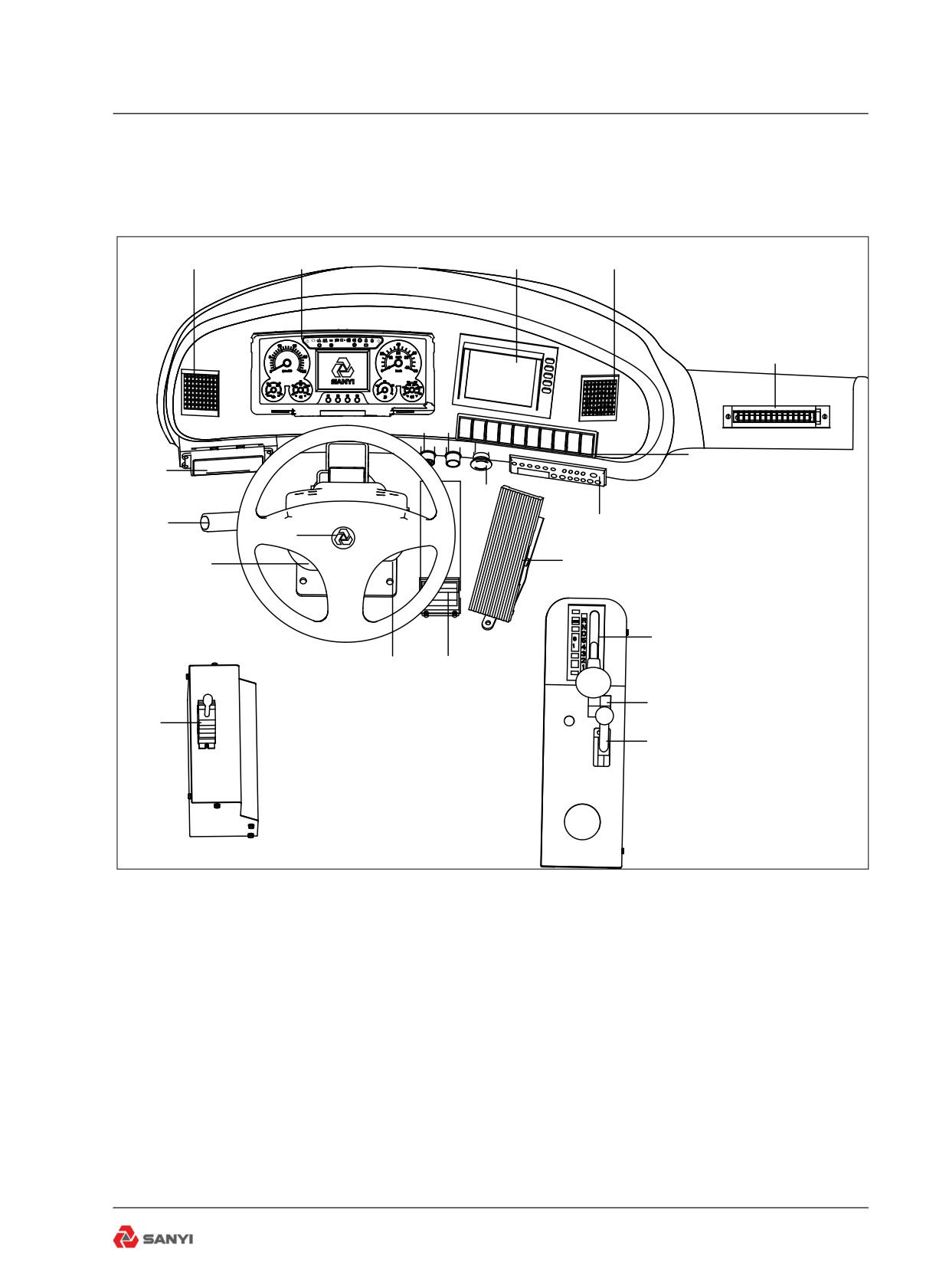
3 CONTROLS AND OPERATING
3.1 Controls and Instruments
1
2
3
4
P
!
!
5
10
9
6
20
8
19
7
18
11
17
12
16
15
13
21
14
Fig 3-1
1. Air outlet
8. Emergency brake button
15. Service brake pedal
9.Botton of solenoid valve
2. Combination instrument
16. Ignition key switch
for body stably control
3. Reversing monitor
10. Cigar lighter
17. Steering column assembly
4. Air outlet
11. Accelerator pedal
18. Horn
5. Air outlet
12. Gear shift lever
19. Combination switch
6. Switch
13. Transmission retarder switch
20. Air conditioner control
7. Radio / MP3
14. Retarder lever
21. Body control lever
3-1
Controls and Operating
1
2
3
4
5
6
7
8
9 10 11
12 13
P
!
!
17
16
15
14
P
!
!
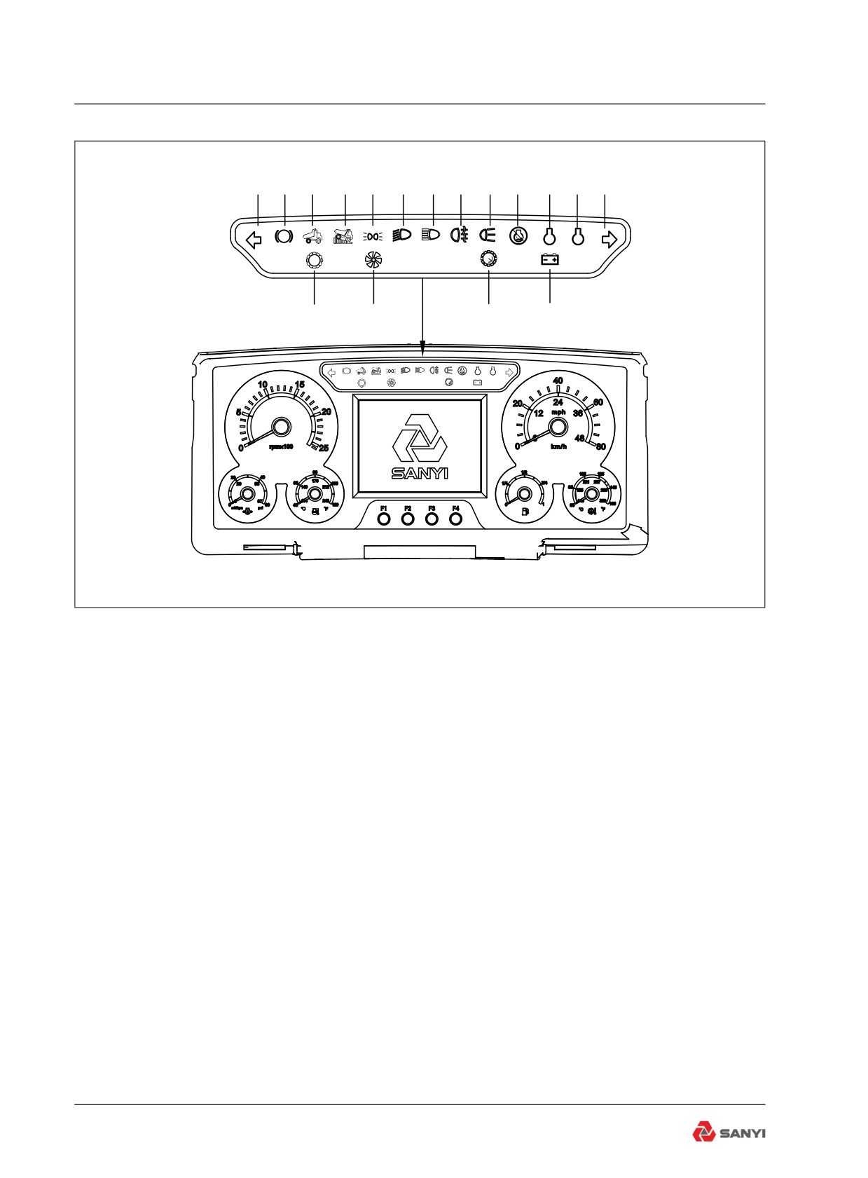
Fig 3-2
3.2 Indicator
1. Left steering indicator (green) - Flashes
when the left indicator lights are operating.
2. Parking brake (red)-Illuminates when the
parking brake is applied.
3. Body up (Yellow) - Illuminates to indicate
that the body is NOT resting on the chassis.
Never move the machine until this light goes
OUT.
4. Retarder indicator (yellow) - Illuminates
when the retarder is applied.
5. Side marker lamp (yellow) - Such lamp will
be on when side marker lamp starts to work.
6. Dipped beam Indicator (green)-Illuminates
when dipped beam start to work.
7. High beam indicator (blue)-Illuminates when
high beam start to work.
8. Fog indicator (yellow) - Such lamp will be on
when fog lamps start to work.
3-2
Controls and Operating
9. Engine stop indicator (red)- Illuminates
when rear lamps start to work.
10. Engine Stop Indicator Red) - When the
'Stop' indicator comes on, the computer has
detected a major malfunction in the engine
that requires immediate attention.
Stop the machine when this light illuminates
and do not operate until the fault is removed.
11. Engine maintenance indicator (white)-
Indicates that the engine needs to be
maintained. See Cummins Manual for details
about specific maintenance items.
12. Engine warning indicator (yellow) -
When the 'Warning' indicator comes on, the
computer has detected a fault in the engine
which may result in a power loss. The fault
should be diagnosed and removed at the
earliest opportunity.
13. Right steering indicator (green)- Flashes
when the right indicator lights are operating.
14. Alternator charging (red) - Illuminates to
indicate when the alternator is not charging.
15. Transmission over speed indicator (red)
- Illuminates when the transmission ECU
senses engine speed above 2350 rev/min.
16. Transmission over speed indicator-
Illuminates when the transmission is in Torque
Converter drive. It goes OUT when Lockup is
engaged.
17. Check trans indicator (red) - Illuminates to
alert of a fault in the transmission shift system
or abnormal transmission temperature. The
light will illuminate when the ignition key switch
is turned to position '1' to provide a bulb and
system check and should go off a few seconds
after the engine is started.
3-3
Controls and Operating
1
2
P
!
!
7
6
5
4
3
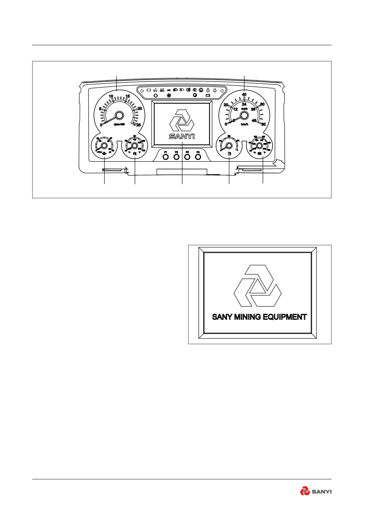
Fig 3-3
3.3 Instruments
1. Tachometer
Driven by CAN bus; it indicates engine speed
in revolutions per minute. When the pointer
is located in white area said speed is normal,
and once the pointer is located in red area
that speed is too high, should reduce speed
SANY MINING EQUIPMENT
immediately.
2. Speedometer
Driven by CAN bus; it indicates vehicle
Fig 3-3.1
running speed. When the pointer is located in
white area said speed is normal, and once the
pointer is located in red area that speed is too
high, should reduce speed immediately.
3. Transmission oil temperature gauge
The pointer indicates transmission oil
temperature value. Such meter is directly
connected to transmission temperature
sensor. When the pointer is located in white
area said transmission oil temperature is
normal, and once the pointer is located in red
area that transmission oil temperature is too
3-4
Controls and Operating
high, movement, the buzzer for 10 seconds,
then shut down automatically. In the electric
power the same fault buzzer action only once.
08-25-2012
15:10:25
Wed
SANY Mining Equipment
4. Fuel level gauge
The pointer indicates percent of full tank
Engine
Transmission
a actual fuel level. Such meter is directly
Monitor
connected to fuel level sensor. When the
VEH DIST
ENG HRS
pointer is located in white area said fuel level
XXXXXX
km
XXXXX.Xh
is normal, and once the pointer is located in
red area that fuel level is too low, movement,
the buzzer for 10 seconds, then shut down
automatically. In the electric power the same
Fig 3-3.2
fault buzzer action only once.
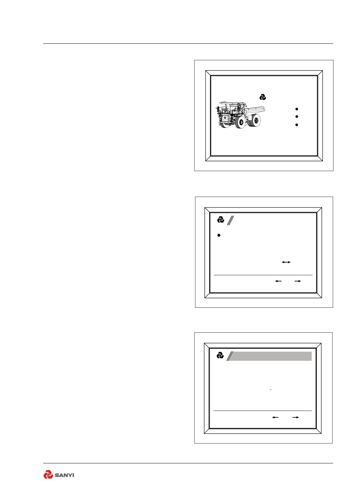
5. Display
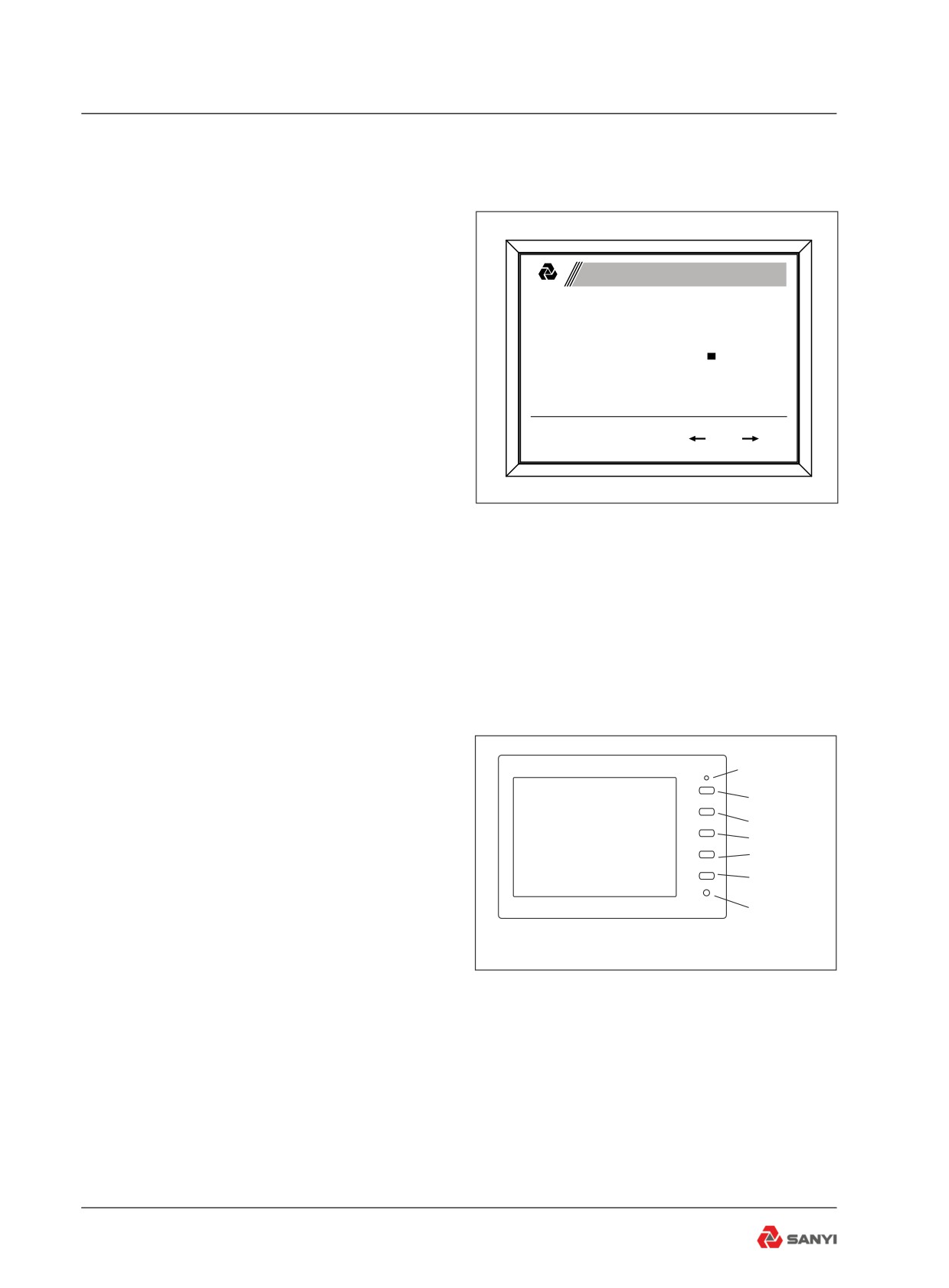
1. Turn on power supply, start the key switch
toΙ, the display shows "sany " boot screen(see
System Function
SANYI
fig3-3.1), and all of the signal indicators are
Engine information
Parameters query
applied, 3 seconds after the display shows
Parameters setting
Monitoring system
work interface, the lights go out at the same
Restore password
Controller I/O
Backlight adjust
time.
System time setting
Buzzer time setting
Chinese
English
2. Click F2 key to change from work interface
to system function interface, and the work
F1:ESC F2:Enter F3:
F4:
interface is default(see fig3-3.2).
3. Enter the system function interface, F1 key
to return, F2 key for confirmation key, the F3
key to move up, and F4 for down key(see fig3-
Fig 3-3.3
3.3),.
4. Under the system function interface, click
the F3 key or F4 key to choose the function
and click F2 key to confirm.
Take the case of setting system time to
System Time Setting
SANYI
demonstrate operation method.
Under the system function interface:
2012Y08M13D
a. click F3 key or F4 key to choose the number
12H30M25S
of the time;
b. click F2 key to confirm, then the cursor will
automatically move to the next number(see
F1: ESC F2: Enter F 3:
F4:
fig3-3.4);
c. When the cursor to the last digit (the second
single digits) , click F2 key to confirm the
current changes, and then click F2 key again
Fig 3-3.4
to end the modify Settings until appear a
3-5
Controls and Operating
square green claim(see fig3-3.5),
d. Click F1 key to return to the system function
interface.
6. Engine Water Temperature Gauge
System Time Setting
Driven by CAN bus; it indicates engine coolant
SANYI
temperature value. When the pointer is located
in white area said engine coolant temperature
2012Y08M13D
is normal, and once the pointer is located in
12H30M25S
red area that engine coolant temperature is too
high, movement, the buzzer for 10 seconds,
then shut down automatically. In the electric
F1: ESC F2: Enter F 3:
F4:
power the same fault buzzer action only once.
7. Engine Oil Pressure Gauge
Fig 3-3.5
Driven by CAN bus; it indicates engine oil
pressure value. When the pointer is located in
white area said engine oil pressure is normal,
and once the pointer is located in red area that
engine oil pressure is too high, movement,
the buzzer for 10 seconds, then shut down
automatically. In the electric power the same
fault buzzer action only once.
3.4 Reversing monitor system
Power Supply
Indicator
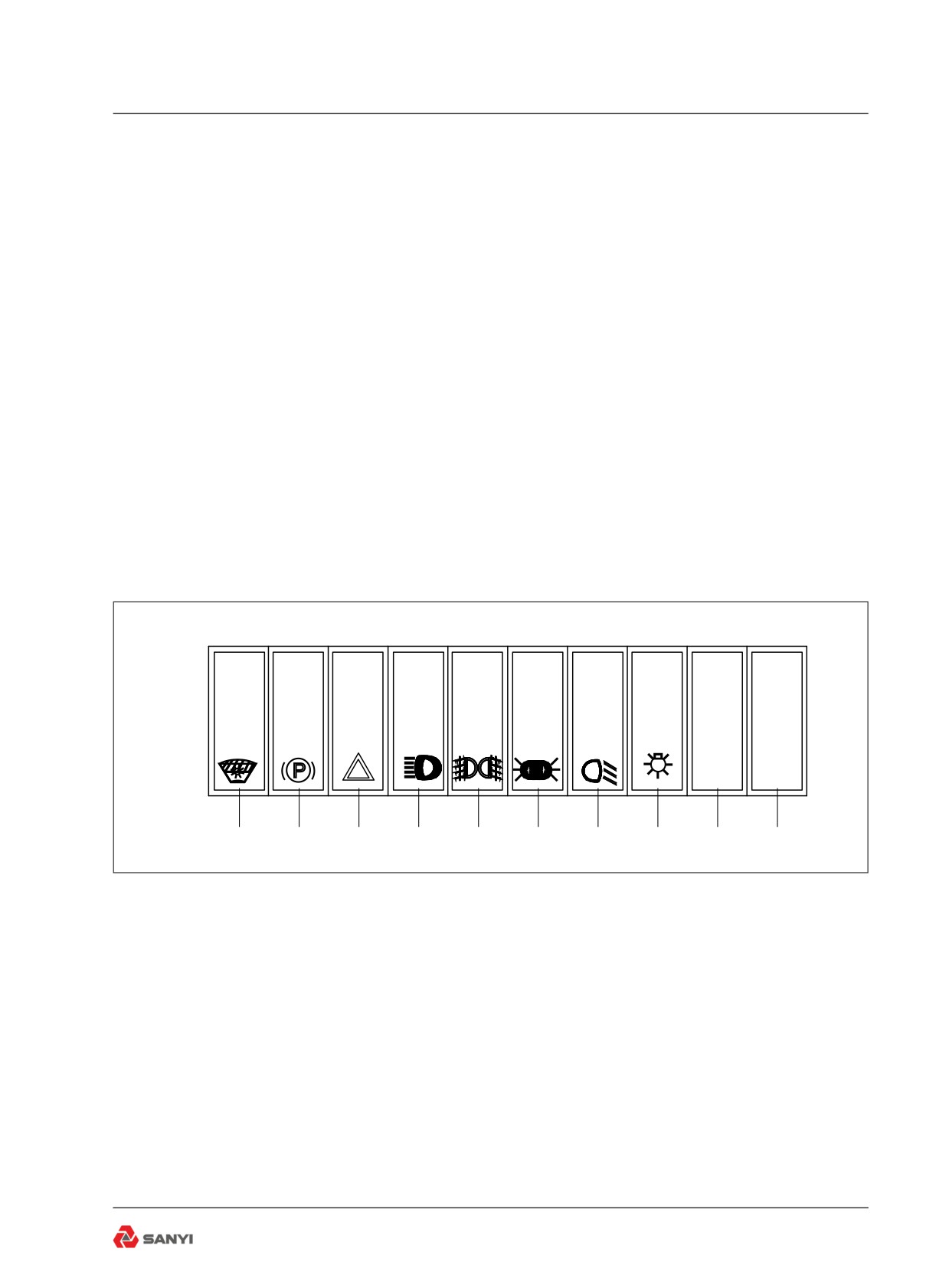
The monitor (see Fig 3-4) on instrument panel
Power
Supply
is mainly used for monitoring the reversing
Menu
truck as well as watching the situation behind
č+Ď
truck. The matching camera is at the rear part
č-Ď
Mirror
of truck.
/Normal
Operation instructions:
Light
1.Power supply switch
Sensor
There are two methods available for turning
on the monitor: The monitor will be turned on
Fig 3-4
automatically when the transmission gear shift
selector is placed at REVERSE position; press
down the power supply key on monitor to turn
on the monitor, and press again to turn off the
monitor.
The power supply indicator(red) will be on
when the monitor is turned on and it will be off
when the monitor is turned off.
2.Contrast control
3-6
Controls and Operating
Press the MENU key until contrast appears
on the screen, then press “+” or “-” key to
increase or decrease image contrast.
3.Brightness control
Press the MENU key until brightness appears
on the screen, then press “+” or “-” key to
increase or decrease image brightness.
4.Volume control
Press the MENU key until volume appears
on the screen, then press “+” or “-” key to
increase or decrease volume.
5.Mirror/ Normal selection
Press such button to set reversal effect of
image.
Reversal image can be displayed when switch
is placed at MIR position.
Normal image can be displayed when switch
is placed at the NOR position.
3.5 Switches
P
1
2
3
4
5
6
7
8
9
10
Fig 3-5
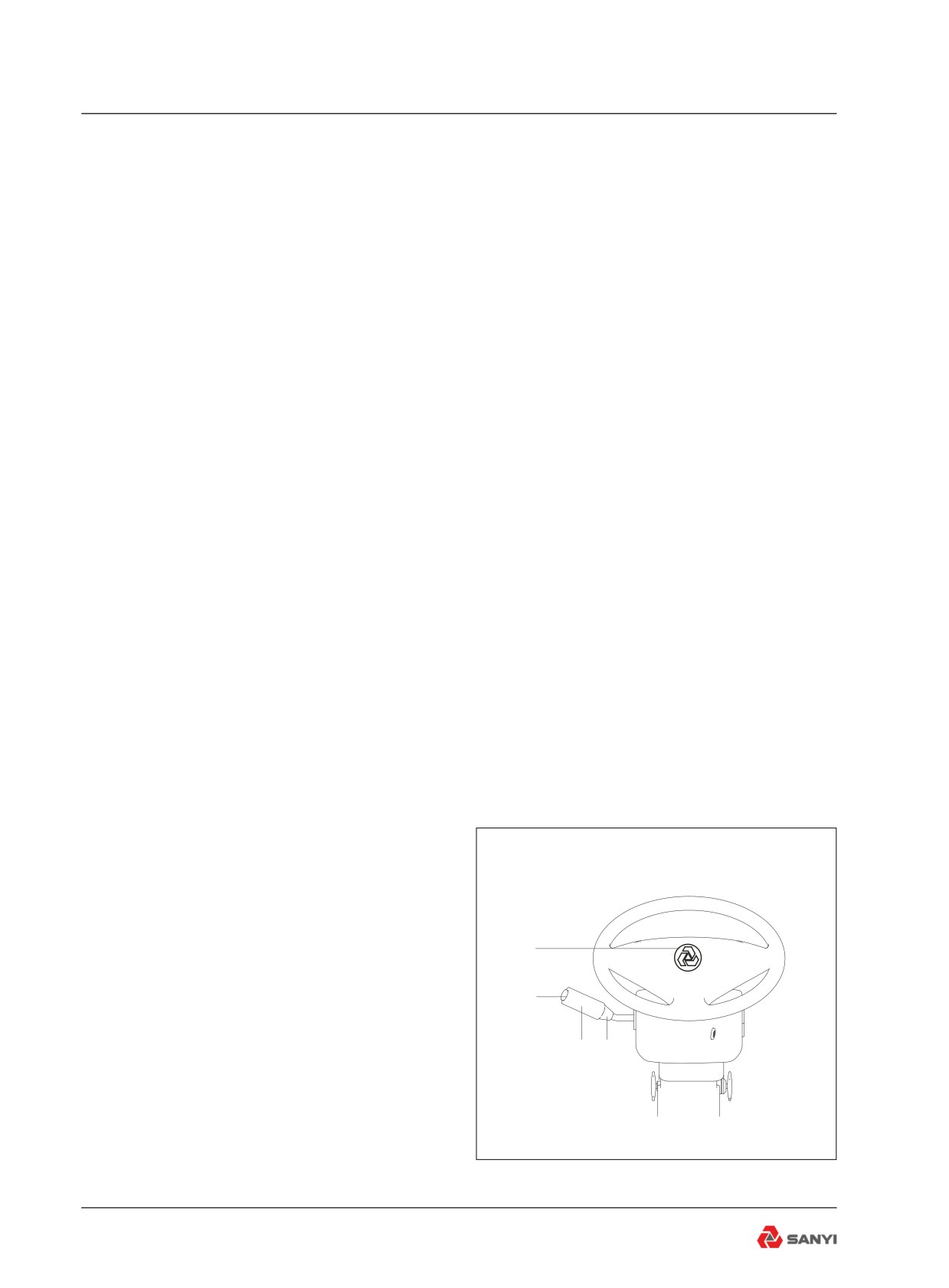
1. Economical/Powerful mode switch
Allows the operator to select between the
transmission 'POWER' and 'ECONOMY' shift
schedules.
Caution: Move the transmission shift lever to
Neutral before selecting schedule.
2. Parking brake switch
The driver can perform rear braking
independently. Such brake can be used for
load parking or stopping.
3. Hazard warning lamp switch
Press bottom of switch to make four steering
3-7
Controls and Operating
lamp flash simultaneous; press the top of the
switch to turn them off.
4. Headlamp switch
Press the bottom of the switch to electrify
the headlamp ( dipped beam/high beam);
the dipped beam/high beam of the combined
switch will be effective; otherwise, they will be
ineffective.
5. Fog lamp switch
Press switch bottom to turn on the rear fog
lamp. Press the upper part of switch to turn off
the rear fog lamp.
6. Clearance lamp switch
Press switch bottom to turn on the front and
rear clearance lamp. Press down the upper
part of switch to turn off the lamp.
7. Rear lamp switch
Press switch bottom to turn on rear lamp,
Press down the upper part of switch to turn off
rear lamp.
8. Small lamp switch
Press switch bottom to turn on rocker switch
indicator. Press down the upper part of switch
to turn off indicator.
9. Backup Switch
10. Backup Switch
3.6 Combined switch
1. Horn
Button pushed in = Horn sounds.
2. Washer
1
Ring Pushed = Windscreen wash
3. Windscreen Wiper
Position J = Not used
2
Position 0 = Stop, reset wiper
Position I = Wiper slow speed
3
4
Position Ⅱ = Wiper fast speed
4. Headlight dipper and flasher
Control downwards = Main beam
Neutral position = Dipped beam
Control upwards = Headlight flash
Fig 3.6
3-8
Controls and Operating
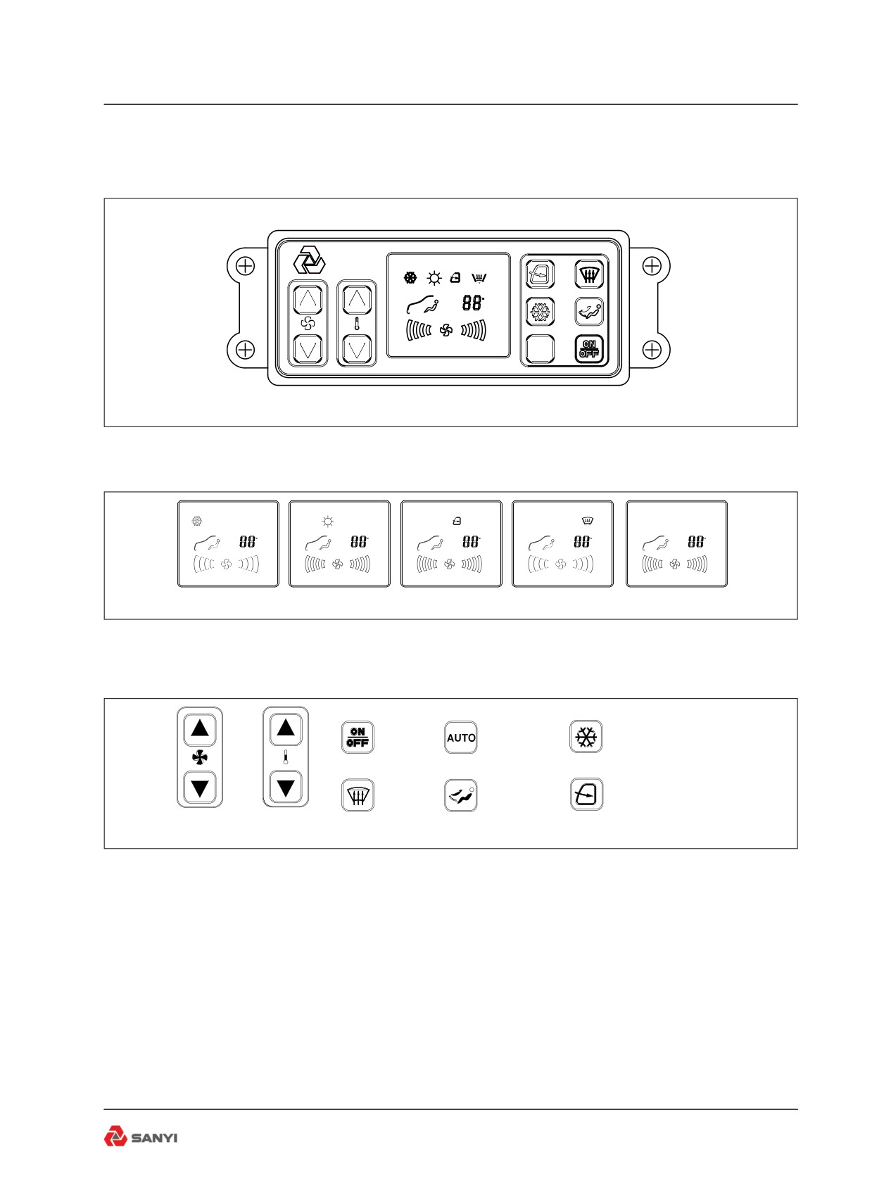
3.7 Air Conditioner Control Panel
Set up
C
Fig 3.7
1. Panel display instructions
Set up
C
Set up
C
Set up
C
Set up
C
Set up
C
Refrigeration mode
Heat mode
Circulating mode
Defrosting mode
Blower mode
Fig 3.7.1
2. Panel key-press instructions
ON/OFF
Auto/ Manual
Refrigeration/ Heat
key-press
key-press
key-press
Defrosting
Blower mode
Air circulating key-press
key-press
key-press
Wind speed
Temperature adjusting
key-press
key-press
Fig 3.7.2
3. Operation instructions
a. Open
Press power supply key to turn on the
machine; the controller will automatically
select the working mode according to the air
conditioning system inside truck; then press
power supply key to turn off power supply and
all the outputs.
b. Blower mode
Press mode key to set air conditioner working
mode (automatic, refrigerating, heating,
3-9
Controls and Operating
ventilating).
c. Refrigeration
Forced refrigerating function:
1. On blower mode, press Refrigeration/ Heat
key-press, air conditioner is on refrigeration
statues, LO will be displayed to activate forced
refrigerating mode when the temperature is
set smaller than 15℃ (larger than 30℃ ) under
refrigerating mode. On refrigeration statues,
press wind speed key-press can adjust wind
speed(low、middle and high).
2. On refrigeration statues, wind speed is on
high(wind speed and night mode can adjust
but temperature can not).
d. Heating mode
Forced heating function: HI will be displayed
to activate forced heating mode when the
temperature is set larger than 30
℃ (smaller
than 15 ℃ ) under heating mode. On heating
statues, press wind speed key-press can
adjust wind speed(low、middle and high).
e. Defrosting mode
1. Press defrosting key-press, it is on defrosting
statues, press wind speed key-press can
adjust wind speed(low、middle and high).
2. Automatic defrosting function: During
refrigerating, the temperature of defrosting
sensor is smaller than 1.5℃ , the compressor
will turn off; it will turn on if the temperature of
defrosting sensor is smaller than 4℃ .On other
status it will enter core defrosting.
f. Press circulation key, i.e., fresh air function;
the external circulation is used for blowing
fresh air and the internal circulation for
stopping fresh air intake.
CAUTION
Air conditioner uses the manual
valve to control warm water, in
summer, must de sure the valve is
shut when refrigerate; in winter, must
be sure the valve is on when heat.
3-10
Controls and Operating
3.8 Driver Seat
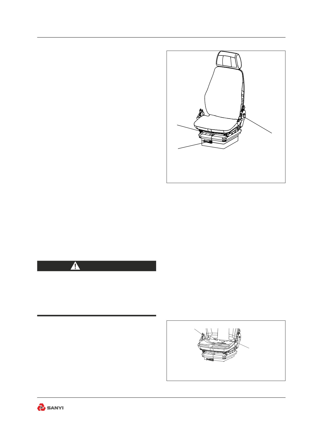
1. The travel of suspension device is 100mm.
2. Body weight and height adjustment. Pull
up the seat can adjust height, there are three
levels(low、middle、high), when the seat is
on high level, if pull up the seat, it will return
low level. The adjusting handle (1) on seat can
adjust the rigidity of suspension mechanism,
2
(the green indication belt on body weight
3
adjustment indication strip is at a visible
position).
1
3. Front/rear adjustment. Pull handle (2) on
the right side to slide seat to a proper position.
The maximum front and rear adjustment
distance is 210mm.
4. Back angle adjustment. This is used to
Fig 3.8
make the driver lean tightly on the seat back.
Pull handle (3) on the left to move the back
to a proper position, and then put down the
handle. The back angle adjustment scope is
larger than 90° .
5. Headrest height adjustment. Adjustment
scope of 105mm (see Fig 3-8).
WARNING
Do not attempt to adjust the seat or
seat belt while the machine is moving.
Loss of control may result. Stop the
machine; apply the brakes;then adjust.
1
3.9 Seat Belt
Adjust the seat to the best height which does
2
not affect the driving. Completely release the
seat belt (1), sit down on the seat, pull out seat
belt (1), and buckle up lock catch (2). In order
to remove the seat belt, press the button on
lock catch (2) to pop up seat belt (1) (see Fig
Fig 3.9
3-9).
3-11
Controls and Operating
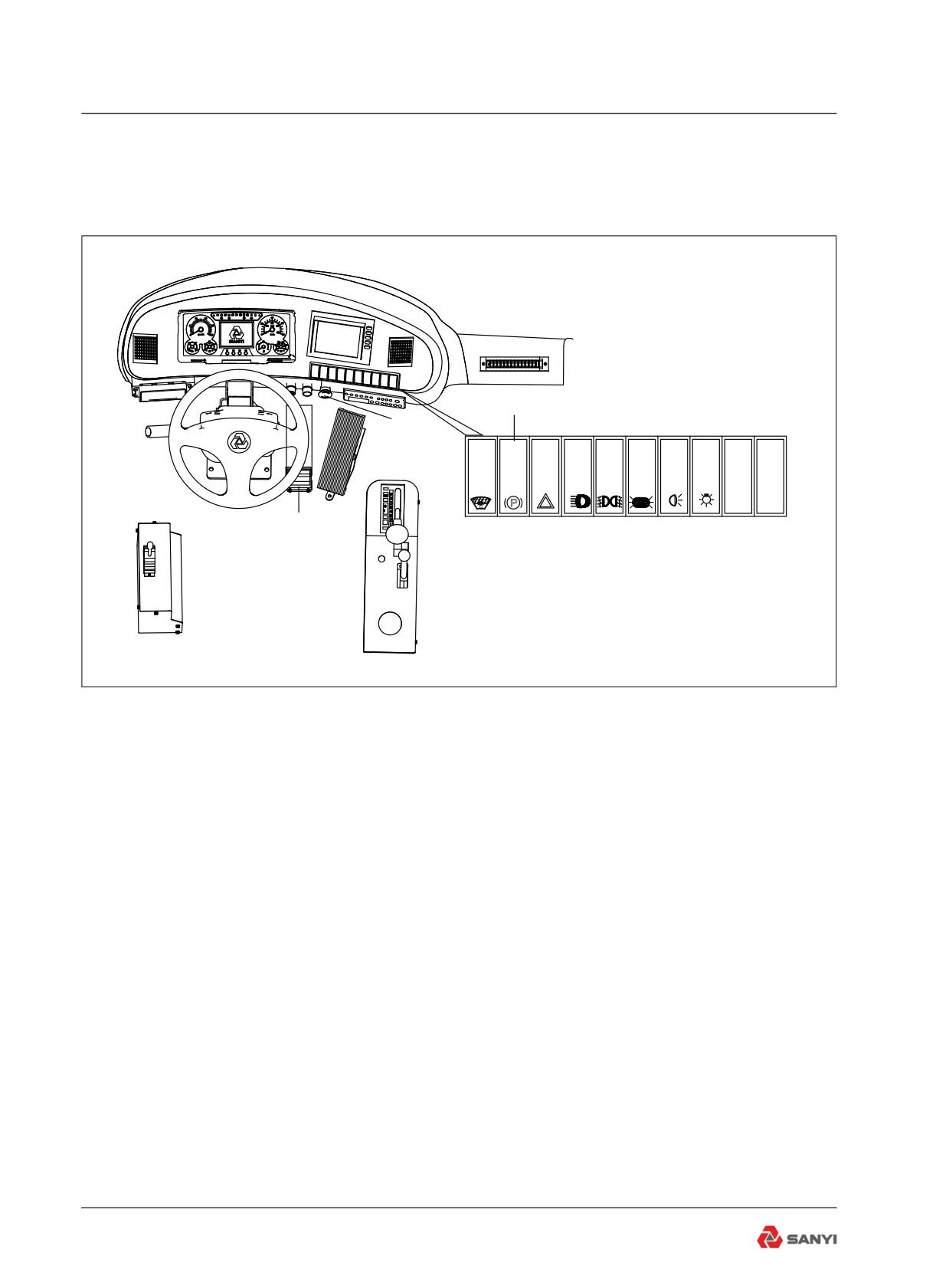
3.10 Truck Controls
!
!
Parking brake
Emergency
brake button
P
Service brake pedal
Fig 3.10
3.10.1 Braking
The truck is provided with following brake
methods: Service brake, parking brake,
emergency brake, retarder, which can be
selected according to the actual condition.
Use service brake during normal operation;
Use parking brake during stopping; Use
emergency brake in an emergency. A
continuous braking force to hold the truck to a
safe steady speed.
3.10.2 Service brake
This is a floor mounted pedal operated by the
right foot. Depress the pedal as required by
speed, load and road conditions to slow or
stop the machine. Release the pedal as the
machine slows until, when stopped, the pedal
is depressed just enough to hold it stationary.
(see Fig 3-10).
3-12
Controls and Operating
3.10.3 Parking brake
Pushing the switch in will apply the spring
operated parking brakes within the rear brake
assemblies and the service brakes at all
wheels. The parking brake indicator on the
combination instrument will illuminate when
the control is pushed in. Push the switch at top
to release the brakes.
WARNING
Always apply the parking brake before
leaving the operator's seat.
3.10.4 Emergency brake
Pushing the control switch in an emergency.
To release the brakes, turn the control
clockwise.
Note: Try to avoid using the control switch.
For normal braking the service brake pedal
should be employed.
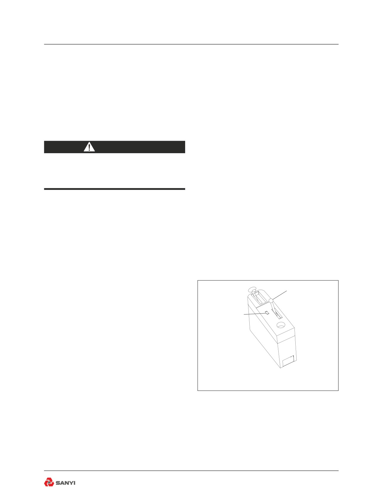
3.10.5 Retarder
Refer to Fig3-11, this truck is equipped with
2
two retarders: the transmission retarder and
the rear disk brake retarder. The handle (2) is
used to control the rear disk brake retarder.
1
The transmission retarder switch (1) is used to
control the transmission retarder.
Retardation is the term used for applying a
continuous braking force to hold the truck
to a safe steady speed when descending
grades. The retarder may be used anytime
to slow down. If additional braking is required
apply the service brakes. The retarder is not
Fig 3.11
meant for bringing the machine to a halt, or
for sudden deceleration - the service brakes
should be employed for this purpose.
When the retarder is applied, the ' Retarder
Indicator Light ' on the instrument panel will
illuminate and an orange coloured warning
indicator at the rear of the truck will illuminate
to warn following trucks.
3-13
Controls and Operating
The retarder is off when the lever is fully
forward and is applied as the lever is pulled
back. Rear disc brake retarder can obtain
different retardation by shifting handle from
front to rear. Maximum retardation is obtained
when the lever is in the fully back position.
(1) Retarder operation
Before the machine crests the top of a grade
and starts down, the operator should slow the
machine with the service brakes and downshift
to the gear range which would be used to
ascend the grade. The retarder should be
applied before starting the descent. Machine
downgrade speed (with the retarder applied
as required) in the gear range selected should
be high enough to keep the engine operating
at governed speed with the throttle closed
(operator's foot off the accelerator pedal).
This will ensure maximum oil circulation and
cooling. If the rate of descent is too slow, the
transmission should be upshifted to the next
highest gear range. If the rate of descent is too
fast, the gear range selected is too high and
the operator must slow the machine by using
the service brakes, then downshift into a lower
gear range which will allow a safe descent and
efficient retarder operation.
The two retarders can be used at the same
time, it is strongly recommended that just one
of them is used and the transmission retarder
is prior. Only when maximum transmission
retardation is obtained and additional
retardation is required, the rear disk brake
retarder be used.
Note: In order to obtain the maximum
retardation and cooling effect during
retardation, the engine speed should be
maintained as high as possible without
exceeding the maximum recommendation.
(2) Oil temperature - rear disc brake
The disc brake hydraulic temperature warning
indicator on the instrument panel will illuminate
and an electric horn will sound if the oil flowing
through the disc brake assemblies overheats.
3-14
Controls and Operating
If alarm is activated, reduce downgrade travel
speed. If the trouble persists, stop the machine
and have the fault corrected.
(3) Oil temperature - transmission
During normal operation the transmission oil
temperature gauge should read in the white z-
one, should not enter the red zone. Otherwise,
reduce downgrade travel speed immediately to
avoid the oil overheating and possible damage
to the transmission.
WARNING
Great care should be used if applying
the retarder when road surfaces are
slippery. Retarder braking effect will
occur only at the driving axle and
could make truck control difficult.
3.11 Engine
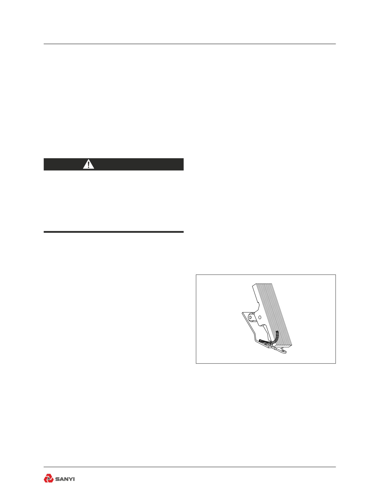
3.11.1 Accelerator pedal
The accelerator pedal provides an electrical
signal to the engine's fuel control system in
proportion to the degree of pedal actuation.
(see Fig3-12).
Note: The electronically controlled engine
will override the accelerator pedal position
until the engine is warmed up to the correct
operating temperature. The engine MUST be
started with foot 'OFF' the accelerator pedal.
Fig 3.12
3.11.2 QUANTUM electronic fuel system
This machine is equipped with the Quantum
Electronic Fuel System, an electronic engine
control system, which continually monitors
the engine and warns the operator when a
problem develops. The system also takes
action to prevent damage to the engine and,
provides the serviceman with diagnostic
capabilities so that problems can be corrected
quickly and easily.
3-15
Controls and Operating
2
1
4
5
6
7
3
P
!
!
Fig 3.13
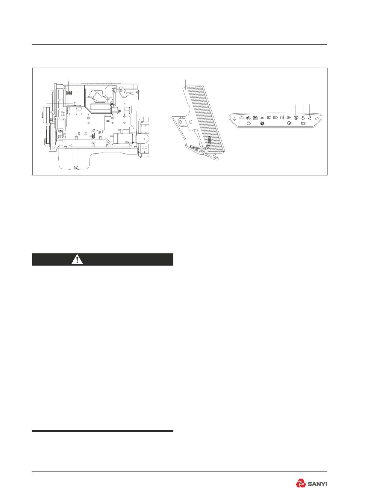
1.Electronic control module (ECM)
5. Stop indicator
2&3. Harness connector (50 and 31pin RHS)
6. Maintenance indicator
4. Accelerator pedal
7. Warning indicator
WARNING
Before any welding is done on a
machine equipped with the Quantum
Electronic Fuel System, disconnect the
following in this order:
Battery earth cable, battery supply
cable, alternator earth cables,
alternator supply cables, transmission
black box connector, ECM interface
harness connector (30 pin RHS), ECM
power harness connector (5 pin RHS)
and ECM sensor harness connector
(30 pin LHS). Turn off ignition key
switch to isolate the batteries before
disconnecting any components.
After welding connect all of the above
in the reverse order.
3-16
Controls and Operating
3.11.3 Quantum electronic fuel system -
description
1. Electronic Control Module (ECM)
Receives electronic inputs from the driver as
well as from mounted sensors that provide
information electronically, such as oil pressure
and temperature and intake manifold pressure.
This information is used to control both the
quantity of fuel injected and injection timing.
2. Programmable Read Only Memory
Located in the ECM and encoded with the
operating software. Additional information
is programmed into the EEPROM. This
information controls the horsepower rating,
torque curve, maximum engine speed and
engine protection devices. The ECM processes
this information and sends electronic signals
to the Electronic Fuel System Injectors where
the precise amount of fuel is injected into the
engine.
3.Electronic Fuel System Injectors
The injector is a lightweight, compact unit that
injects diesel fuel directly into the combustion
chamber. The amount of fuel injected and the
beginning of injection timing is determined by
the ECM. The ECM sends a command pulse
which activates the injector solenoid.
The injector performs four functions:
a - Creates the high fuel pressure required for
efficient injection.
b - Meters and injects the exact amount of fuel
required to handle the load.
c - Atomizes the fuel for mixing with the air in
the combustion chamber.
d - Permits continuous fuel flow for component
cooling.
Electronic fuel system injectors are self
compensating and virtually eliminate engine
tune-ups.
Note: Never apply 12V or 24V directly to
terminals on the injector as it will burn out.
Before removing injectors.
3-17
Controls and Operating
3.11.4 QUANTUM electronic fuel system
- operation
When the 'Stop' indicator on the dash panel
illuminates, the computer has detected a
major malfunction in the engine that requires
immediate attention. It is the operators
responsibility to shut down the engine to avoid
serious damage.
The machine is equipped with an engine
protection derate system, which records fault
codes when an out-of-range conditions is
found. The Maintenance indicator illuminates
when the engine protection derate system
is initiated. The engine power and speed
will be gradually reduced depending on the
level of severity of the out-of-range condition.
The Maintenance indicator will start to flash
if the out-of-range condition continues to get
worse. The operator MUST shut down the
engine to avoid serious damage,The engine
should not be restarted after it has been shut
down after activation of the engine protection
derate system unless the problem has been
diagnosed and corrected.
Conditions that will cause the amber
Maintenance indicator to come on are:Low
coolant level, High coolant temperature, Idle
validation/throttle pedal switch mismatch, High
intake manifold temperature, Low oil pressure
and High fuel rail pressure.
Whenever the 'Stop', 'Warning' or Maintenance
indicator comes on, the Electronic Fuel
System computer will determine where the
problem is and will store this information in
its memory. If the malfunction is intermittent,
the indicators will come on and go off as
the computer senses the changing engine
condition.
A special diagnostic data reader (INSITE) is
available that can be plugged into the engine
computer memory to extract information
related to the cause of the problem. Once
the malfunction has been corrected, the
3-18
Controls and Operating
Electronic Fuel System will return the engine
to normal operation. The data reader can now
distinguish between active codes and those
stored in the historic code memory (inactive
codes). Inactive codes can only be viewed
using the data reader. The fault code recorded
in the ECM memory will remain until it is
erased by a technician.
The operator can check for active faults by
turning the ignition key switch to the 'OFF'
position, switching the diagnostic switch
'ON' and then turning the ignition key switch
to position '1'. If no active fault codes are
recorded, all three ('Stop', 'Warning' &
Maintenance) indicators will come on and
stay on. If active codes are recorded, all three
indicators will come on momentarily. The
yellow ('Warning') and red ('Stop') indicators
will begin to flash the code of the recorded
fault. The fault codes flash in the following
sequence: the yellow indicator flashes once,
then there is a pause where both indicators
are off. Then the numbers of the recorded fault
code flash in red. There is a pause between
each number. When the number is done, the
yellow indicator flashes again. e.g. yellow
flashes once - pause - red flashes twice -
pause - red flashes three times - pause - red
flashes five times - pause - yellow flashes
once, indicates fault code 235. The number
will repeat in the same sequence until the
system is advanced to the next active fault
code or the diagnostic switch is switched to
the 'OFF' position.
Refer to 'Electronic Fuel System Diagnostic
Codes' table for fault code descriptions.
3-19
Controls and Operating
3.11.5 Electronic fuel system diagnostic codes
Detection Codes of Electronically Controlled Fuel System
Error Code
Description
Fault lamp
111
Engine Control Module - Critical internal failure
Red
Engine Speed/Position Sensor Circuit - lost both of two signals from the magnetic
115
Red
pickup sensor
Engine Speed/Position Sensor Circuit - lost one of two signals from the magnetic
121
Yellow
pickup sensor
122
Intake Manifold Pressure Sensor #1 Circuit - shorted high
Yellow
123
Intake Manifold Pressure Sensor #1 Circuit - shorted low
Yellow
131
Accelerator Pedal Position Sensor Circuit - shorted high
Red
132
Accelerator Pedal Position Sensor Circuit - shorted low
Red
133
Remote Accelerator Pedal Position Sensor Circuit - shorted high
Red
134
Remote Accelerator Pedal Position Sensor Circuit - shorted low
Red
135
Engine Oil Pressure Sensor Circuit - shorted high
Yellow
141
Engine Oil Pressure Sensor Circuit - shorted low
Yellow
143
Engine Oil Pressure Low - Warning
Yellow
144
Engine Coolant Temperature Sensor Circuit - shorted high
Yellow
145
Engine Coolant Temperature Sensor Circuit - shorted low
Yellow
147
Accelerator Pedal Position Sensor Circuit - low frequency
Red
148
Accelerator Pedal Position Sensor Circuit - high frequency
Red
151
Engine Coolant Temperature High - Critical
Red
153
Intake Manifold Temperature Sensor #1 Circuit - shorted high
Yellow
154
Intake Manifold Temperature Sensor #1 Circuit - shorted low
Yellow
155
Intake Manifold Temperature #1 High -Critical
Red
187
Sensor Supply Voltage #2 Circuit -shorted low
Yellow
Additional OEM/Vehicle Diagnostic Codes have been logged. Check other ECM's
211
None
for DTC's.
212
Engine Oil Temperature Sensor Circuit - shorted high
Yellow
213
Engine Oil Temperature Sensor Circuit - shorted low
Yellow
214
Engine Oil Temperature High - Critical
Red
219
Low Oil Level in the Centinel makeup oil tank
Maint.
221
Ambient Air Pressure Sensor Circuit - shorted high
Yellow
222
Ambient Air Pressure Sensor Circuit - shorted low
Yellow
223
Engine Oil Burn Valve Solenoid Circuit - shorted low
Yellow
227
Sensor Supply Voltage #2 Circuit - shorted high
Yellow
234
Engine Speed High - Critical
Red
3-20
Controls and Operating
235
Engine Coolant Level Low - Critical
Red
241
Vehicle Speed Sensor Circuit - data incorrect
Yellow
242
Vehicle Speed Sensor Circuit - tampering has been detected
Yellow
245
Fan Clutch Circuit - shorted low
Yellow
254
Fuel Shutoff Valve Circuit - shorted low
Red
255
Fuel Shutoff Valve Circuit - shorted high
Yellow
259
Fuel Shutoff Valve - stuck open
Red
Engine Speed/Position Sensor #1 (Crankshaft) Supply Voltage Circuit - shorted
284
Yellow
low
285
SAE J1939 Multiplexing PGN Timeout Error
Yellow
286
SAE J1939 Multiplexing Configuration Error
Yellow
287
SAE J1939 Multiplexing Accelerator Pedal Sensor System Error
Red
288
SAE J1939 Multiplexing Remote Throttle Data Error
Red
293
Auxiliary Temperature Sensor Input # 1 Circuit - shorted high
Yellow
294
Auxiliary Temperature Sensor Input # 1 Circuit - shorted low
Yellow
295
Ambient Air Pressure Sensor Circuit - data incorrect
Yellow
297
Auxiliary Pressure Sensor Input # 2 Circuit - shorted high
Yellow
298
Auxiliary Pressure Sensor Input # 2 Circuit - shorted low
Yellow
299
Engine Shutdown Commanded by J1939
Yellow
311
Injector Solenoid Valve Cylinder #1 Circuit - grounded circuit
Yellow
312
Injector Solenoid Valve Cylinder #5 Circuit - grounded circuit
Yellow
313
Injector Solenoid Valve Cylinder #3 Circuit - grounded circuit
Yellow
314
Injector Solenoid Valve Cylinder #6 Circuit - grounded circuit
Yellow
315
Injector Solenoid Valve Cylinder #2 Circuit - grounded circuit
Yellow
319
Real Time Clock - Power Interrupt
Maint.
341
Engine Control Module - data lost
Yellow
343
Engine Control Module - Warning internal hardware failure
Yellow
346
Engine Control Module - Warning Software error
Yellow
349
Transmission Output Shaft (Tailshaft) Speed High - Warning
Yellow
352
Sensor Supply Voltage #1 Circuit - shorted low
Yellow
378
Fueling Actuator #1 Circuit - open circuit
Yellow
379
Fueling Actuator #1 Circuit - grounded circuit
Yellow
386
Sensor Supply Voltage #1 Circuit - shorted high
Yellow
387
Accelerator Pedal Position Sensor Supply Voltage Circuit - shorted high
Yellow
394
Timing Actuator #1 Circuit - open circuit
Yellow
395
Timing Actuator #1 Circuit - grounded circuit
Yellow
396
Fueling Actuator #2 Circuit - open circuit
Yellow
3-21
Controls and Operating
397
Fueling Actuator #2 Circuit - grounded circuit
Yellow
398
Timing Actuator #2 Circuit - open circuit
Yellow
399
Timing Actuator #2 Circuit - grounded circuit
Yellow
415
Engine Oil Pressure Low - Critical
Red
WIF /
418
Water in Fuel Indicator High -Maintenance
Maint.
422
Engine Coolant Level Sensor Circuit - data incorrect
Yellow
426
SAE J1939 datalink - cannot transmit
None
428
Water in Fuel Sensor Circuit - shorted high
Yellow
429
Water in Fuel Sensor Circuit - shorted low
Yellow
431
Accelerator Pedal Idle Validation Circuit - data incorrect
Yellow
432
Accelerator Pedal Idle Validation Circuit - out of calibration
Red
433
Intake Manifold Pressure Sensor Circuit - data incorrect
Yellow
434
Power Lost without Ignition Off
Yellow
435
Engine Oil Pressure Sensor Circuit - data incorrect
Yellow
441
Battery #1 Voltage Low - Warning
Yellow
442
Battery #1 Voltage High - Warning
Yellow
443
Accelerator Pedal Position Sensor Supply Voltage Circuit - shorted low
Yellow
449
Fuel Pressure High - Warning
Yellow
451
Injector Metering Rail #1 Pressure Sensor Circuit - shorted high
Yellow
452
Injector Metering Rail #1 Pressure Sensor Circuit - shorted low
Yellow
466
Turbocharger #1 Wastegate Control Circuit - shorted low
Yellow
482
Fuel Pressure Low - Warning
Yellow
483
Injector Metering Rail #2 Pressure Sensor Circuit - shorted high
Yellow
484
Injector Metering Rail #2 Pressure Sensor Circuit - shorted low
Yellow
485
Injector Metering Rail #2 Pressure High - Warning
Yellow
486
Injector Metering Rail #2 Pressure Low - Warning
Yellow
489
Transmission Output Shaft (Tailshaft) Speed Low - Warning
Yellow
496
Engine Speed/Position Sensor #2 (Camshaft) Supply Voltage
Yellow
527
Auxiliary Input/Output #2 Circuit - shorted high
Yellow
528
OEM Alternate torque validation switch - data incorrect
Yellow
529
Auxiliary Input/Output #3 Circuit - shorted high
Yellow
546
Fuel Delivery Pressure Sensor Circuit - shorted high
Yellow
547
Fuel Delivery Pressure Sensor Circuitshorted low
Yellow
551
Accelerator Pedal Idle Validation Circuit - shorted low
Yellow
553
Injector Metering Rail #1 Pressure High - warning level
Yellow
581
Fuel Supply Pump Inlet Pressure Sensor Circuit - shorted high
Yellow
582
Fuel Supply Pump Inlet Pressure Sensor Circuit - shorted low
Yellow
3-22
Controls and Operating
583
Fuel Supply Pump Inlet Pressure Low - warning level
Yellow
595
Turbocharger #1 Speed High - warning level
Yellow
596
Electrical Charging System Voltage High - warning level
Yellow
597
Electrical Charging System Voltage Low - Warning Level
Yellow
598
Electrical Charging System Voltage Low - Critical Level
Red
611
Engine Hot Shutdown
None
753
Engine Speed/Position #2 - Cam sync error
None
755
Injector Metering Rail #1 Pressure Malfunction
Yellow
758
Injector Metering Rail #2 Pressure Malfunction
Yellow
951
Cylinder Power Imbalance between cylinders
None
3-23
Controls and Operating
3.12 Steering
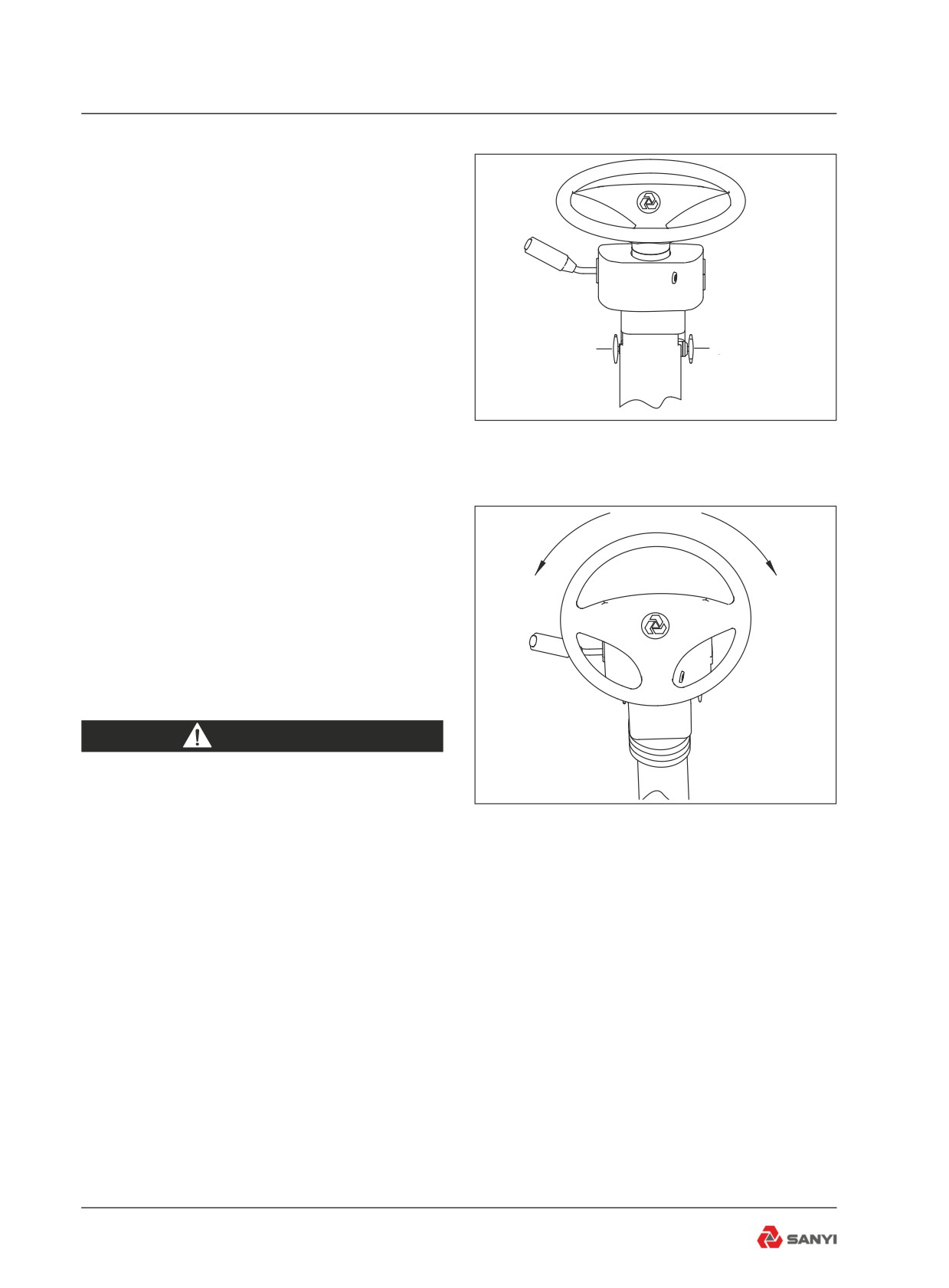
The steering wheel position can be adjusted
as required for the most convenient operating
position. To adjust, pull out adjustment lock
and tilt steering wheel up or down as desired;
release lever to lock adjustment.
The steering system provides full-time
Adjusting rotary
Adjusting rotary
hydraulic power with a continuous-running
knob of high-low
knob of front-rear
pump and a pressurized accumulator. The
accumulator helps maintain a constant flow
of hydraulic power to operate the steering
Fig 3.14
cylinders (Fig 3-14, 3-15).
To steer the front wheels, rotate the steering
wheel in the desired direction to the required
radius of turn. The front wheels will turn only
as the steering wheel is turned and at a rate of
turning directly proportional to steering wheel
Trun left
Trun right
speed. The front wheels will stop and hold
position when the steering wheel is stopped.
To return the front wheels to the straight ahead
position or to the opposite direction, turn the
steering wheel in the opposite direction.
WARNING
In the event of loss of steering pump
output pressure, a fully-pressurize
Fig 3.15
accumulator provides a maximum
of two lock to lock turns of the front
wheels. A red warning indicator on
the instrument panel illuminates and a
buzzer sounds when steering pressure
falls below 11.5MPa (1660 pound/in2).
If this warning indicator illuminates,
indicating a loss of steering power, the
machine must be stopped immediately
and no further operation attempted
until the fault is corrected. The
accumulator slowly bleeds down after
engine shut-off to prevent accidental
steering. However, accumulator
pressure should be dissipate after
engine shut-off by turning the steering
3-24
Controls and Operating
wheel in both directions to avoid
accidental steering during bleed down.
Improper steering control unit repair or
hose connections can cause sudden
and forceful steering wheel movement
when engine is started.Keep hands off
steering wheel when starting engine.
3.13 Transmission
3.13.1 CEC2 Shift System
The transmission of the truck adopts the
CEC2 (2nd generation commercial electronic
control) shift system. CEC2 is a well designed
computer-controlled automatic shift system,
which integrates functions including automatic
gear-shift, misoperation screening, diagnostic
capabilities, etc., so as to effectively reduce
the fatigue of the driver and make the driver
work safely, easily and simply by focusing on
the road conditions.
Automatic Gear-shift: CEC2 can automatically
select appropriate gear position according
to throttle position, engine speed and truck
speed. Do not move the gear shift handle
frequently during driving. The truck speed can
be controlled through controlling oil supplied
to throttle position by foot pedal. CEC2 can
select economy mode and power mode.
So as to meet the different requirements of
customers.
Reverse Inhibit: Prevents gear selection if
engine is operating at more than 20% throttle.
Hoist interlock pressure switch - The ECU will
shift the transmission from Reverse to Neutral
if the body control lever is moved to the 'Raise'
position.When the body is held in the 'Raise'
position,will prevent to engage reverse gear.
Body Up Interlock: When the body is raised, the
CEC2 system will only allow the transmission
to operate in first gear. This feature is only
operational in the normal automatic driving
mode, either power or economy. It is not
3-25
Controls and Operating
activated during the manual mode.
Parking Brake Interlock: If the parking brake
is applied while the transmission is in neutral,
the CEC2 system will prevent a shift out of
neutral to protect the brake components. If the
parking brake is applied while the transmission
is in gear, the parking brake interlock will not
function and normal shifts will occur.
Lock-in-gear: The lock-in-gear feature is
designed to protect the transmission from
damage should wheel spinning or lockup occur
due to poor traction or panic braking. The ECU
will delay making a shift for several seconds
and then, if the condition fails to correct itself,
locks in gear and prevents any further shifting.
The transmission fault indicator will come on.
If this occurs, the ECU must be reset before
normal operation may be resumed.
Reset procedure: if the transmission has
locked in gear because of wheel spinning
or emergency brake, stop the truck, select
neutral, apply the parking brake, and shut
down the engine. Turn off battery main switch,
wait ten seconds, then reconnect the main
switch and restart the engine. Select reverse,
then neutral. The "check transmission" and
"inhibit gear shift" warning indicator should go
off.
Cold Weather Starts: During cold weather
starts, if the transmission temperature is
below -24℃ (-10°F), The "check transmission"
and "forbid gear shifting" warning indicator
will come on, and the ECU will keep the
transmission at neutral gear. Between -24° C
(-10°F) and -7℃ (19°F) ,the warning indicator
will go out and the ECU will only permit
operation in First or Reverse gears. Above
-7℃ (19°F), normal operation will be permitted.
WARNING
Before any welding is done on a
machine equipped with a CEC shift
3-26
Controls and Operating
system, disconnect battery equalizer
ground cables, battery cables from
terminal posts (ground cable first),
battery equalizer positive cables
and electrical connections at the
ECU to avoid damage to electrical
components. Turn off ignition key
switch to isolate the batteries before
disconnecting any components.
The standard procedure for raising the
body must still be adhered to.
3
P
8
7
6
5
2
4
1
P
!
!
10
9
Fig 3.16
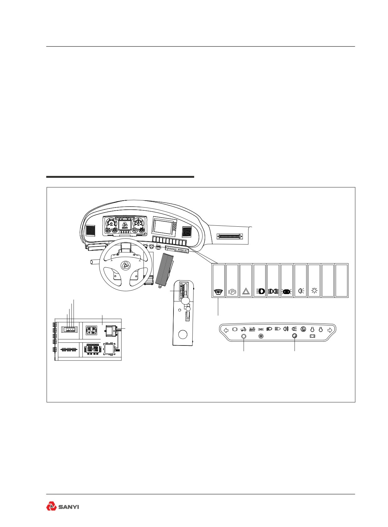
1.Electronic control unit (ECU)
6. Diagnosis switch
2.Control box
7.Stalling detection switch
3.Gear shift selector
8.Idling adjustment switch
4.Mode selection switch
9. Transmission overspeed indicator
5.Reversing switch
10.Transmission fault indicator
3-27
Controls and Operating
3.13.2 Introduction and operation
(1) Electronic Control Unit (ECU) - The ECU
contains an electronic microcomputer.It
receives information in the form of electronic
signals from switches and sensors, processes
the information, and sends electronic signals
to the appropriate solenoids which control the
transmission.
(2) Control box -- contains VIM and ECU.
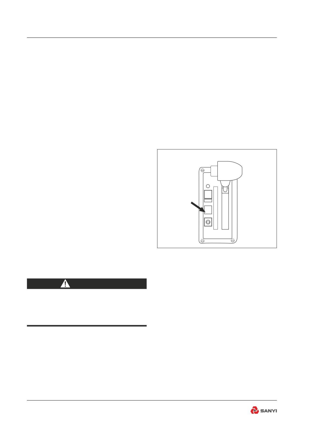
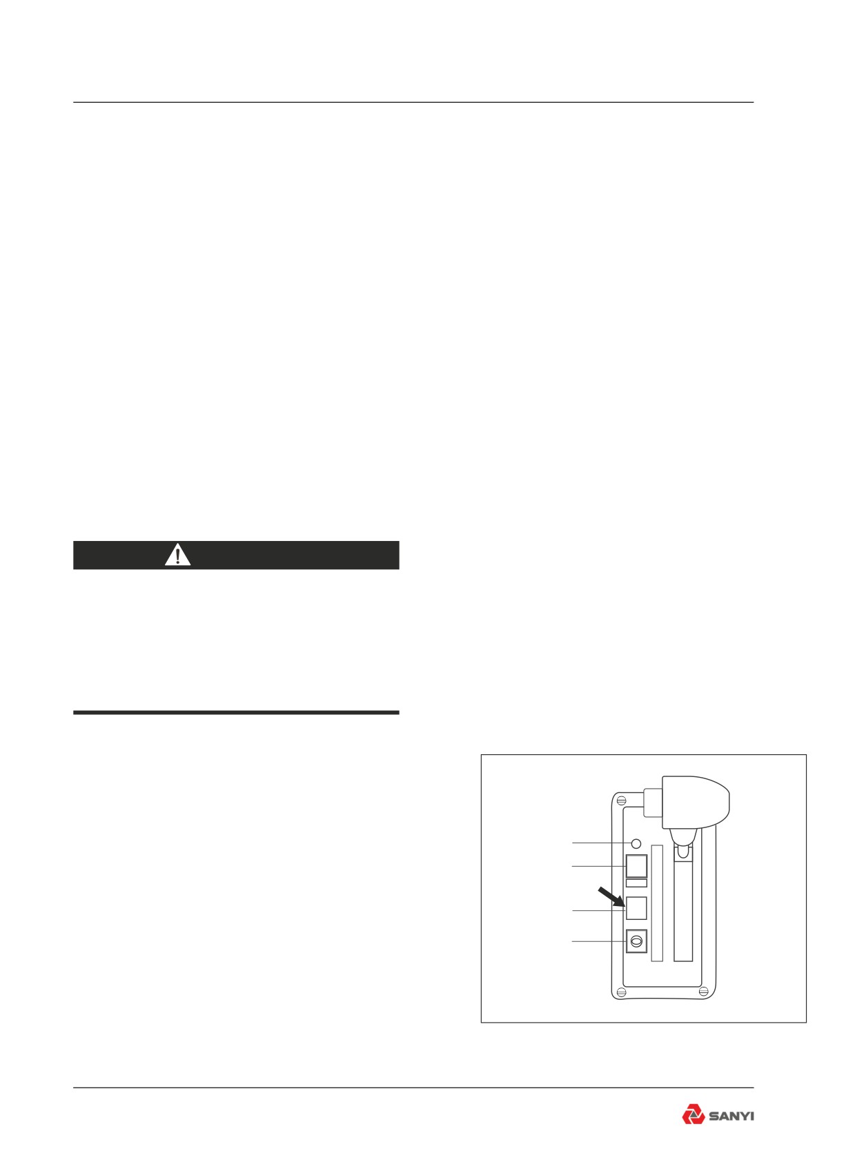
(3) Gear shift selector -- the shift selector is
a remote mounted lever type. The gear shift
selector is connected to the ECU by a wiring
harness. The shift lever has 6 forward ranges
and 1 reverse ranges, as well as a neutral
position.
The shift selector has a single digit LED
display, which during normal operation
R
MODE
N
will display the gear selected. Diagnostic
D
information can be displayed on the single
5
R
4
digit LED display by pressing the diagnostic
3
display button. There is a hold override button
2
1
that must be pressed when shifting between R,
N and D. The hold override button is released
when desired selector position is reached. The
selector lever can move freely between D and
Fig 3.17
the number ranges without pressing the hold
override button. (Refer to fig.3-17)
WARNING
Do not allow the vehicle to coast in
Neutral. This practice can result in
severe transmission damage.
The transmission upshifts and downshifts
automatically between first range and the
highest range selected on the range selector
in direct response to throttle position, engine
speed and transmission output speed.
When Reverse is selected the reverse alarm
sounds and the reverse indicator illuminates
at the rear of the vehicle. This feature warns
personnel to the immediate rear of the vehicle
3-28
Controls and Operating
that the operator has shifted to reverse.
When drive 'D' is selected, the transmission
automatically upshifts and downshifts through
all six forward ranges as required by loads and
travel speeds. Selecting a lower range (4th,
3rd etc.) limits the highest range to which the
transmission will automatically upshift.
If a lower range is selected while moving
forward, the transmission automatically
downshifts sequential to the selected lower
range at maximum controlled engine speeds.
Downshifts will not occur until vehicle is
slowed by use of the service brakes and/or
retarder.
When shifting from neutral to start from a
standstill, or to reverse direction, decelerate
the engine to idle speed. To move forward,
select drive 'D' and accelerate the engine to
the vehicle load and speed requirements. The
transmission will automatically upshift from 1st
through 6th ranges as travel speed increases.
With the throttle fully depressed, and the
mode selection switch in the Power position,
the transmission upshifts to the next higher
range when the engine attains 2175rpm, since
maximum power train output is needed under
this condition. At lower throttle settings where
minimum power train performance is required,
the transmission will upshift to the next higher
range at less than maximum rated engine
speed.
Upgrades or soft spots might slow travel
speed, even at full throttle, requiring
transmission downshifts to maintain maximum
powertrain performance. When this occurs,
the transmission downshifts automatically.
Shift the transmission to the next lowest range
if transmission 'Hunting' or 'Shift Cycling'
occurs.
When temporarily stopped, such as for
yielding the right-of-way to a loaded vehicle,
the transmission can be left in the selected
range and the vehicle held stationary with the
service brakes.
3-29
Controls and Operating
However, when stopped for a more extended
period with the engine left running, shift the
transmission to neutral to avoid unnecessary
heat buildup and apply the parking brake.
WARNING
Always select Neutral and apply the
parking brake before leaving the
operator’s seat.
(4) Mode selection switch - Gives the option
to select between transmission 'POWER' and
'ECONOMY' shift schedules.
Note: The transmission must be in neutral
before the switch will function; otherwise,this
practice can result in transmission damage.
The transmission torque converter is equipped
with a lockup clutch which, when engaged
by the ECU, locks the converter pump and
turbine together as a single unit and allows
power to be transmitted mechanically from
the engine directly to the transmission gearing
on a 1 to 1 ratio. When the lockup clutch is
disengaged, the torque converter acts as a
fluid coupling, multiplying torque when engine
speed is significantly higher than transmission
output shaft speed.
When the mode selection switch is in the
'POWER' position, the ECU controls operation
of the lockup clutch according to signals
received by the throttle position sensor (giving
engine speed as a percent of throttle), the
transmission output shaft speed sensor,
and range selector. The ECU may delay
application of the lockup clutch and allow
torque multiplication by the torque converter to
take place until a balance is achieved between
engine speed and transmission output shaft
speed before activating the lockup clutch.
Power versus Economy Mode
The POWER mode is designed for
applications involving heavy loads and hilly
3-30
Controls and Operating
duty cycles where performance rather than
fuel economy is of prime importance.
The ECONOMY mode is designed for
applications involving lighter loads and level
duty cycles or where fuel economy is more
important than performance.
In the ECONOMY mode, the ECU controls
operation of the lockup clutch with a timed,
preprogrammed schedule where in second
through sixth gears the lockup clutch is
disengaged only long enough to allow the
torque converter’s fluid coupling to absorb
shift shock. Otherwise, the lockup clutch is
engaged and no torque multiplication takes
place in Second through Sixth gears.
(5)Reversing switch-This switch is provided for
reversing function,Operator can use.
(6)Diagnosis switch -- This switch is provided
for the professional service technician of the
engine, and is used to retrieve fault codes of
the engine. By default, this switch is opened
by pressing its bottom (lower) part.
(7) Stall check -- This switch is provided for
the professional service technician of the
transmission, and is used to test the matching
between the transmission and the engine
output torque. By default, this switch is opened
by pressing its top (upper) part.
(8)Idling adjustment switch-This switch is
provided for idling adjustment function,
operator can use to increase or decrease
idling.
(9)Transmission over speed indicator (Red)
-- Illuminates when the transmission ECU
senses engine speed above 2350 r/min.
(10) Transmission fault indicator(Red) --
Illuminates to alert of a minor fault in the
transmission shift system or abnormal
transmission temperature. The warning
indicator will come 'On' when the ignition key
switch is turned to position '1' to provide a bulb
and system check and should go 'Off' a few
seconds after the engine is started and the
transmission oil pressure rises.
3-31
Controls and Operating
The transmission fault indicator will come
'On' during operation if the ECU has detected
a minor fault in an electrical component or
abnormal transmission oil temperature. If
transmission oil temperature is too high, stop
the machine, select Neutral (N), and increase
engine speed to allow a greater flow of oil
to the oil cooler until oil temperature drops
to normal operating range. In most cases, a
minor fault triggering the transmission fault
indicator will not prevent normal operation
from continuing but, depending on the nature
of the problem, the ECU could take action to
protect the transmission from damage, such
as preventing operation in high gear ranges. If
the ' check trans ' warning indicator comes on,
have the problem diagnosed and corrected at
the earliest opportunity.
WARNING
Do not operate engine for more
than 30 seconds at full throttle with
transmission in gear and output stalled
as this will result in severe overheat
damage to the transmission.
3.13.3 General Transmission Operation
Watch for wide deviations from normal
readings on the transmission oil
temperature gauge during truck operation. If
the transmission oil
4
R
temperature gauge, on vehicles which do not
MODE
3
N
have a transmission retarder fitted, shows
D
5
oil temperature consistently rising above the
R
4
2
green zone (65°C - 135°C; 149°F - 275°F)
3
2
under normal operating conditions; check for
1
1
external causes. If none are evident shift to
Neutral (N) and operate the engine at 1200 -
1500 r/min. If the transmission oil temperature
does not decrease into the green zone within
Fig 3.18
2 or 3 minutes, the cause of the overheating
3-32
Controls and Operating
should be corrected before the machine is
operated further. Watch the oil temperature
gauge when operating on upgrades, also. If
the oil temperature goes into the red zone
(135°C -165°C; 275°F- 392°F), select the
range which will limit upshifts to the highest
range in which the transmission will operate
within the normal temperature range. If
upshifting must be consistently limited to
ranges lower than normal for the loads and the
grades encountered to prevent overheating
the transmission oil, the causes should be
determined and corrected.
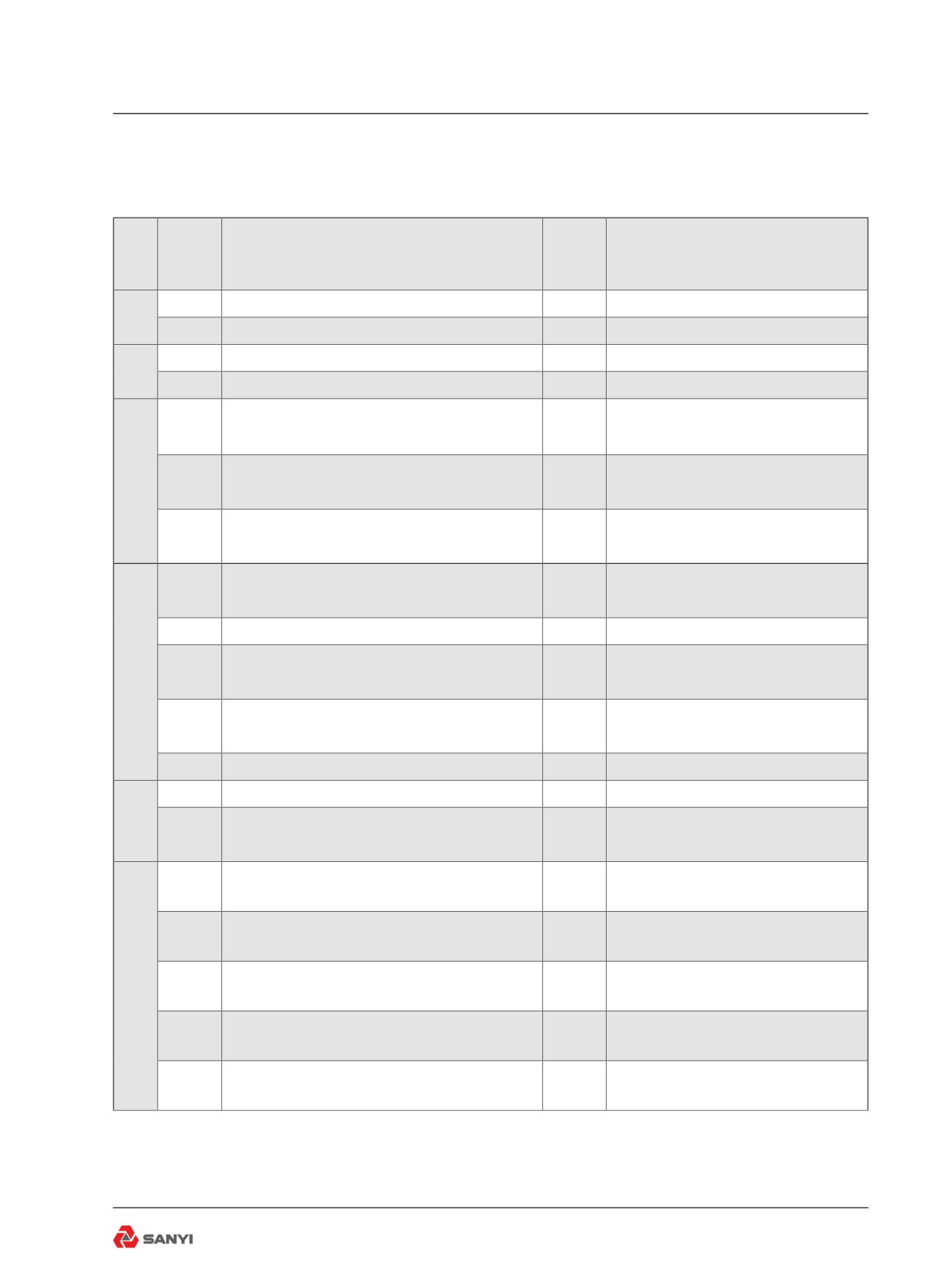
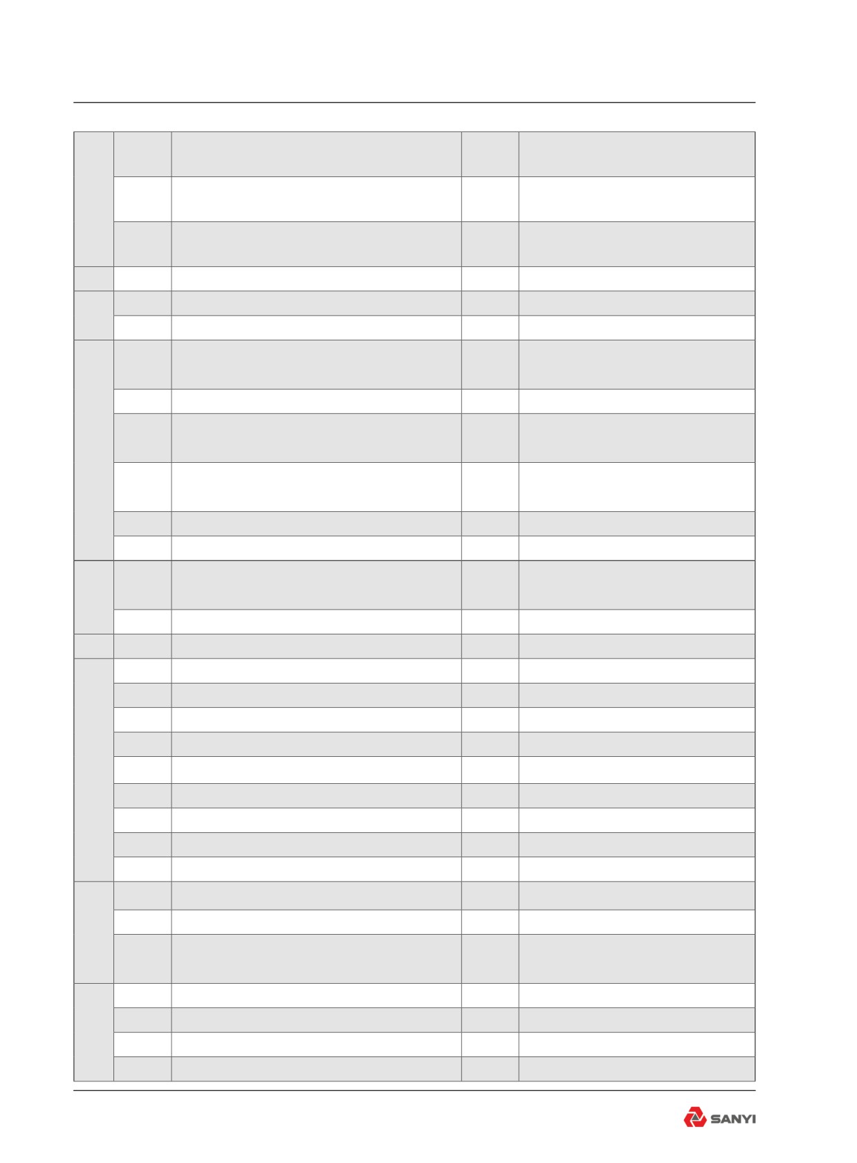
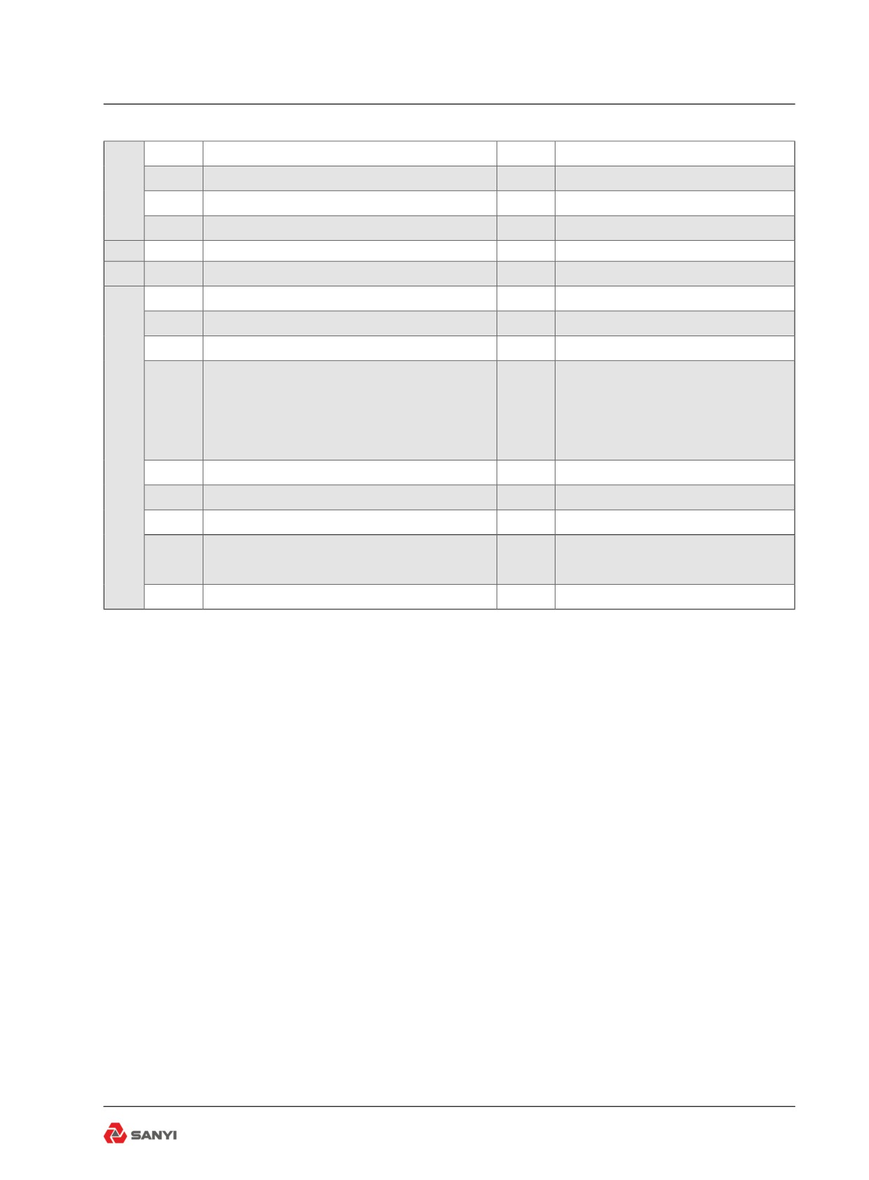
3.13.4 Retrieving Diagnostic Codes
Diagnostic fault codes can be retrieved from
the CEC2 system using the gear shift selector
or by plugging in the diagnostic data reader
(DDR). To obtain diagnostic codes using the
gear shift selector:
※Check transmission warning indicator on
dash will illuminate when ECU detects a fault.
※Stop truck and select 'Neutral'.
※Press diagnostic button (1) on gear shift
selector. Display (2) on gear shift selector will
flash one digit at a time.
※Display starts with code position D1, D2,
etc, followed by the two digit main code, then
the two digit subcode.
※To advance to the next code, press the
mode button (3). Up to five codes can be
stored.
※Active codes are indicated by illumination of
the mode light (4).
3.13.5 Clearing Diagnostic Codes
To clear active codes, press and hold mode
button (4) for 3 to 5 seconds.
To clear inactive codes, press and hold mode
button (4) for 8 to 10 seconds.
To exit diagnostic mode, press diagnostic
button (6). Refer to table for diagnostic code
description.
3-33
Controls and Operating
3.13.6 Diagnostic Codes
Check
Main
Sub
Inhibited Operation
Description
Trans
code
Code
Description
Light
12
ECU input voltage, low
Yes
DNS
13
23
ECU input voltage, high
Yes
DNS
12
Throttle position sensor, failed low
Yes
Use throttle default values
21
23
Throttle position sensor, failed high
Yes
Use throttle default values
Engine speed sensor reasonableness
14
Yes
Use default engine speed
test
Turbine speed sensor reasonableness
22
15
Yes
DNS, lock in current range
test
Output speed sensor reasonableness
16
Yes
DNS, lock in current range
test
Hold in last valid direction. May
12
Primary shift selector or RSI link fault
Yes
cause “cateye” display
13
Primary shift selector mode function fault
No
Mode change not permitted
Secondary shift selector or RSI link
Hold in last valid direction. May
23
14
Yes
fault
cause “cateye” display
Secondary shift selector mode
15
No
Mode change not permitted
function fault
16
Shift Selector display line fault
Yes
None. May cause “cateye” display
12
Sump fluid temperature, cold
Yes
DNS, lock-to-range
24
No upshifts above a calibration
23
Sump fluid temperature, hot
Yes
range
Output speed sensor, detected at 0 output
11
Yes
DNS, lock in current range (1st)
rpm, 1st
Output speed sensor, detected at 0 output
22
Yes
DNS, lock in current range (2nd)
rpm, 2nd
Output speed sensor, detected at 0 output
25
33
Yes
DNS, lock in current range (3rd)
rpm, 3rd
Output speed sensor, detected at 0 output
44
Yes
DNS, lock in current range (4th)
rpm, 4th
Output speed sensor, detected at 0 output
55
Yes
DNS, lock in current range (5th)
rpm, 5th
3-35
Controls and Operating
Output speed sensor, detected at 0 output
66
Yes
DNS, lock in current range (6th)
rpm, 6th
Output speed sensor, detected at 0 output
25
77
Yes
DNS, lock in current range (7th)
rpm, 7th
Output speed sensor, detected at 0 output
88
Yes
DNS, lock in current range (8th)
rpm, 8th
26
00
Throttle source not detected
No
Use throttle default values
12
Sump fluid temperature sensor failed low
Yes
Use default value of 93°C (200°F)
33
23
Sump fluid temperature sensor failed high
Yes
Use default value of 93°C (200°F)
Factory calibration compatibility number
12
Yes
DNS, SOL OFF
wrong
13
Factory calibration fault
Yes
DNS, SOL OFF
Use previous location, or factory
14
Power off fault
Yes
34
calibration
Use previous location, or clear
15
Diagnostic queue fault
Yes
diagnostic queue
16
Real time fault
Yes
DNS, SOL OFF
17
Customer modifiable constants fault
Yes
DNS, SOL OFF
Power interruption (code set after power
None (hydraulic default during
00
No
35
restored)
interruption)
16
Real time write interruption
Yes
DNS, SOL OFF
36
00
Hardware/software not compatible
Yes
DNS, SOL OFF
12
General solenoid failure - F
Yes
DNS
13
General solenoid failure - K
Yes
DNS, Inhibit lockup
14
FGeneral solenoid failure - B
Yes
DNS, Inhibit Reverse
15
General solenoid failure - G
Yes
DNS
45
21
General solenoid failure - H/J
Yes
Turn off trim boost J, DNS H
22
General solenoid failure - A
Yes
No action taken
23
General solenoid failure - D
Yes
DNS
24
General solenoid failure - I
Yes
No action taken
26
General solenoid failure - C
Yes
DNS
21
Hi side overcurrent, H/J solenoid
Yes
Turn off H/J solenoid, DNS
26
Hi side overcurrent, C, D, E solenoid circuit
Yes
Turn off C, D, E solenoids
46
DNS. Turn off A, B, F, G, I, K
27
Hi side overcurrent, A, B, F, G, I, K
Yes
solenoids
11
Range verification ratio test, 1st
Yes
DNS
22
Range verification ratio test, 2nd
Yes
DNS
56
33
Range verification ratio test, 3rd
Yes
DNS
44
Range verification ratio test, 4th
Yes
DNS
3-36
Controls and Operating
55
Range verification ratio test, 5th
Yes
DNS
66
Range verification ratio test, 6th
On
DNS
56
77
Range verification ratio test, 7th or R1
Yes
DNS
88
Range verification ratio test, 8th or R2
Yes
DNS
65
00
Engine rating too high
Yes
DNS, Lock-in-neutral
66
00
Serial communications interface fault
No
Use default throttle values
27
ECU, inoperative A, B, F, G, I, K solenoid
Yes
DNS, SOL OFF
28
ECU, inoperative H/J solenoid
Yes
DNS, SOL OFF
29
ECU, inoperative C, D, E solenoid
Yes
DNS, SOL OFF
Reset ECU, shutdown ECU on 2nd
ECU, Computer Operating Properly (COP)
occurrence (power loss; hydraulic
33
Yes
fault
defaults). May cause “cateye”
display or all segments blank display
69
34
ECU, EEPROM, fault
Yes
DNS, SOL OFF
35
ECU, EEPROM, fault
Yes
Reset ECU
39
Communication chip addressing error
Yes
Use defaults for J1939 data
GPO 1-8 and reverse warning
42
SPI output failure
No
inoperable
43
SPI input failure
Yes
DNS, lock-in-range
3-37
Controls and Operating
3.14 Body Control
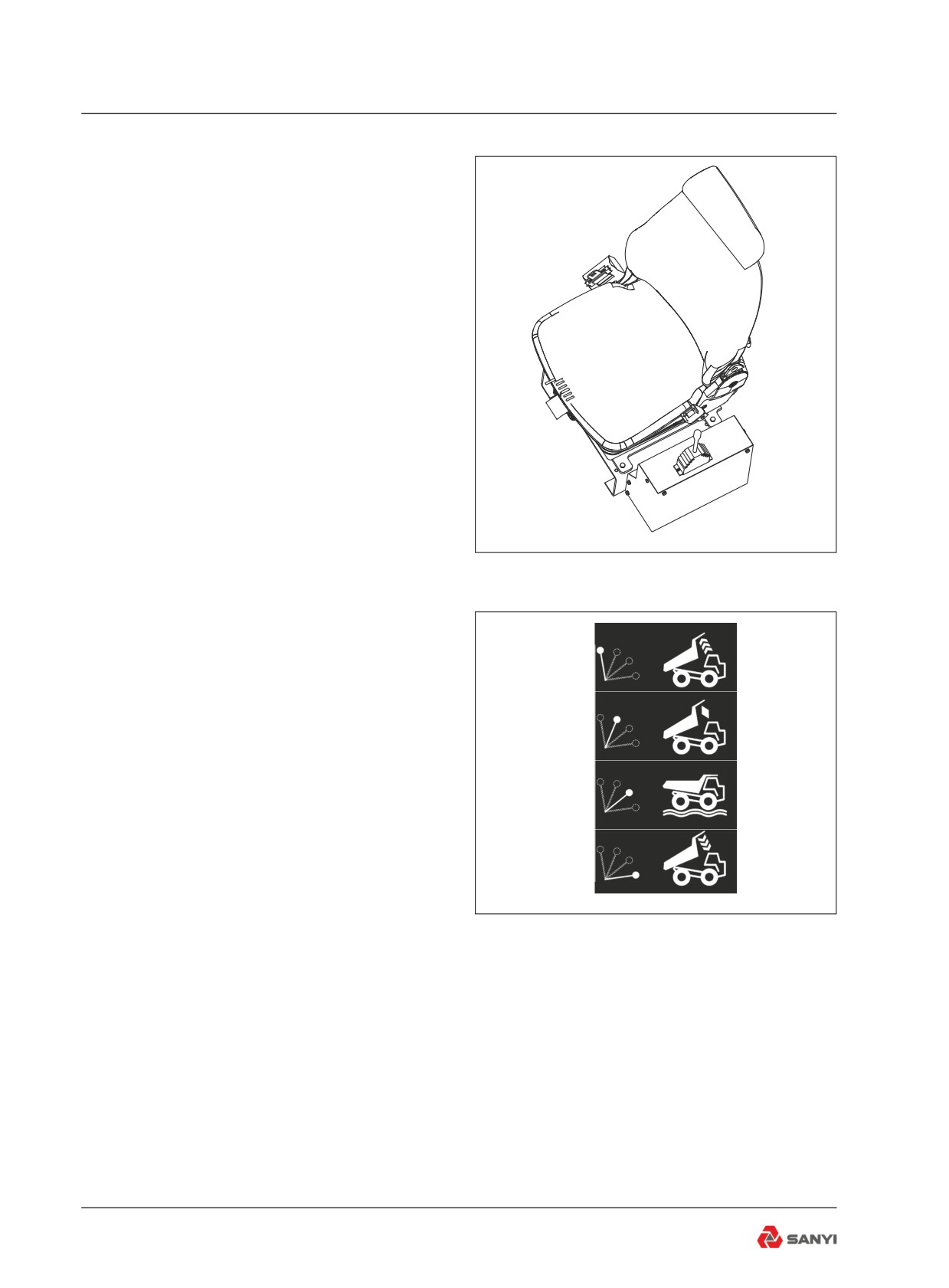
Operate the hoist lever(see Fig 3-19) the left
of operator’s seat to raise or lower body. The
four operating positions of the lever from front
to rear are as follows :
Raise -this position directs oil to extend the
body hoists and raise the body.
When released, the lever will be spring-
returned to the 'HOLD' position.
HOLD - Lever to this position while the body
is being raised and lowered to stop movement
and hold the body to the expected height.
The lever will be locked and kept at “ HOLD”
position during releasing.
FLOAT - While the body drops via gravity, the
lever will be moved to and kept at this position
until the body will be operated again. The lever
Fig 3.19
shall be kept at “float” position during the truck
is in motion .
Lower -This position provides hydraulic force
to power-down the body. The body raised to
HOIST
the highest position needs to be dropped with
hydraulic power, i.e., the lever shall be pushed
HOLD
to this position; when the body is dropped to
a certain height, it will drop via gravity. Then,
release lever and the lever will be moved to
FLOAT
the float position via spring which inside of the
valve (see Fig 3-20).
1. Hoist
LOWER
Preparation:
(1) Run the engine in idling speed;
(2) Make sure the rear wheels are on the firm
Fig 3.20
level ground;
(3)Shift the transmission to Neutral and hold
the machine stationary by applying the brakes
with the Parking-Emergency brake control.
Hoisting:
(1) Pull the lever backward to the “Raise”
position, hold the lever and accelerate engine
to raise body;
(2) Moves the raise lever to "hold" position
when the body is required to stay at a certain
height;
3-38
Controls and Operating
(3) Decelerate the engine when the last stages
of the body hoists begin to extend to slow the
raising speed as the hoists approach their
maximum extensions;
(4) Pull the lever to “HOLD” position when the
body is raised to the desired height.
WARNING
Drain the pressure form the pilot valve
before while repairing the raise system and
its control system .
Method: Turn off the engine, operate the
RAISE lever for about 15 times in two
directions, to drain the pressure oil form
the pilot valve.
2. Lower
Lowering the body:
(1) Move the handle to “float” position; then
the body will lower to the frame via gravity;
(2) If the body is required to stay at a certain
height, the handle shall be moved to “HOLD”
position;
(3) If the body does not begin to lower
by its own weight, such as after dumping
downgrade, move the control lever all the way
forward to the 'LOWER' position and power
the body downward until it begins lowering
by gravity. Then move the lever to 'FLOAT'
position in the specially situation.
Caution : Make sure that the body is
completely lowered and the control lever is
in 'FLOAT' before releasing the brakes and
moving the machine.
3-39
Controls and Operating
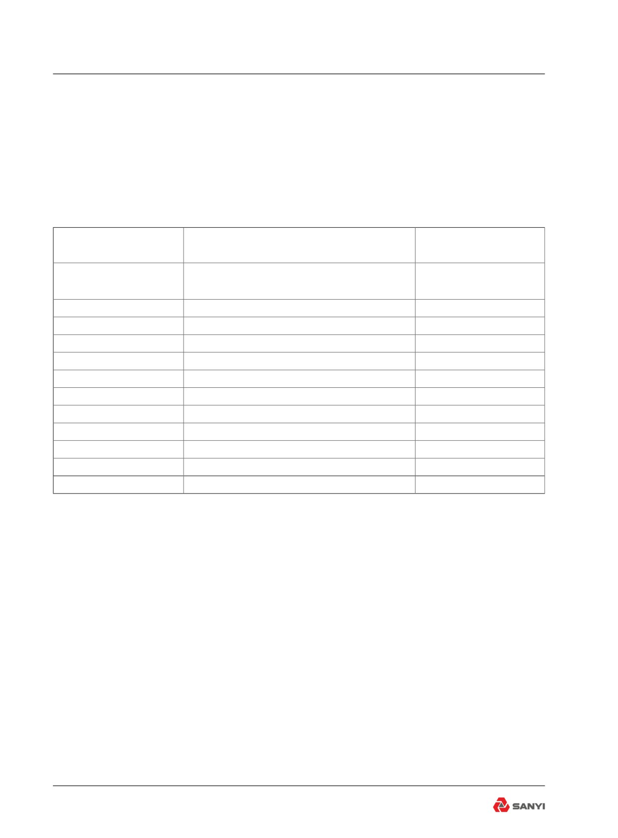
3.15 The common fault code of
vehicle monitor system
There is an indicator of vehicle monitor system
state in display. The indicator is green when
the vehicle is normal, and turns red when any
one or more of the following fault accruing.
Fault code
Description
Operation Instruction
Disc brake cooling oil returning
2685
Must check
Temperature high
2690
Transmission oil filter block
Must check
2691
Transmission oil temperature high
Must check
2693
Brake accumulator pressure F low
Must check
2694
Brake accumulator pressure B low
Must check
2696
Steering accumulator pressure low
Must check
2697
Steering oil returning temperature high
Need check
2698
Steering oil returning filter block
Need check
2700
Water in fuel indicator
Need check
2701
Parking pressure low
Must check
2705
Over speed
Reduce speed
2706
Hoist oil returning filter block
Must check
3-40