SANY SRT45 Off-Highway Truck. Safety,Operation and Maintenance Manual (2014) - page 4
Operating the Truck
4 OPERATING THE TRUCK
4.1 Pre-Starting Inspection
※ Before the engine is started ensure the
machine is ready for operation.
※ The machine should be in a level position to
permit accurate checking of fluid quantities in the
engine and other components.
※ Make sure parking brake is applied and block
wheels securely to prevent accidental movement
of the machine while checking component levels.
※ Test all lights, warning signals, controls and
instruments for proper operation.
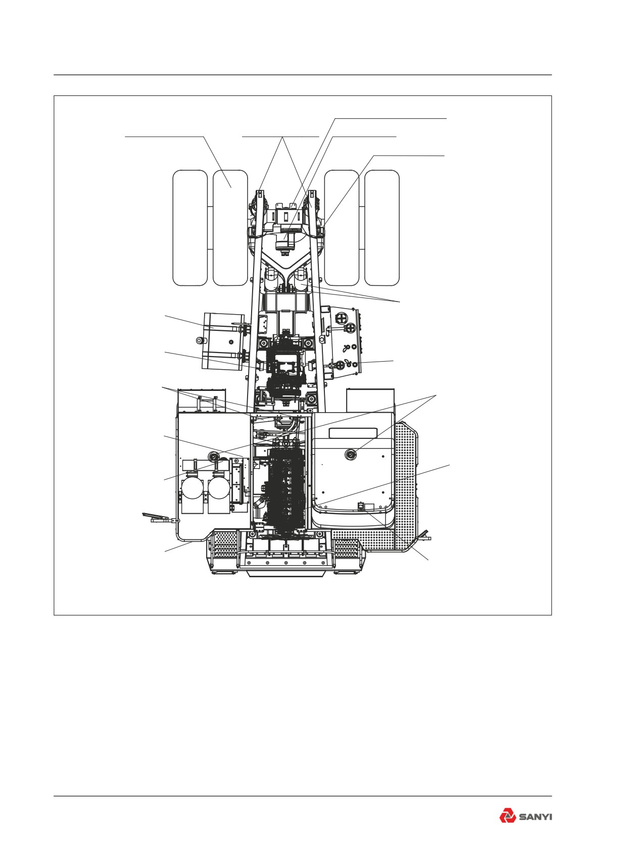
※ Walk around the machine and carry out the
Inspections and Component Checks described
in the drawing opposite and on the following
pages.
4-1
Operating the Truck
Rear lamp assembly Check for leakage
REAR RIDE CYLINDERS
and normal working
WHEELS AND TYRES Check condition,
Check for debris leaks and
inflation, nuts and for damaged rims
damage. Check height
DIFFERENTIAL Check for leaks
DISC BRAKE ASSEMBLIES Check for leaks
BODY CYLINDERS Check for debris,
leaks and damage. Check lines for
FUEL TANK Check fuel level.
wear and leaks.
Ensure fuel tank is full.
Check that tank is securely mounted.
TRANSMISSION Check oil level.
Check for leaks
Hydraulic oil tank Check oil level.
Check for leaks
STEERING CYLINDERS Check for
debris, leaks and damage.
FRONT RIDE CYLINDERS
Check lines for wear and leaks
Check for debris, leaks and
damage. Check height
BRAKE ACCUMULATORS
Check for leaks.
ENGINE Check oil level.
Check liquid level of expan-
Check for leaks
sion water tank and leakage
Front lamp assembly Check
for damage and normal working
CAB, PLATFORM AND STEPS Check
for cleanliness. Check seat belts.
Fig 4.1
4-2
Operating the Truck
4.2 Check of each component
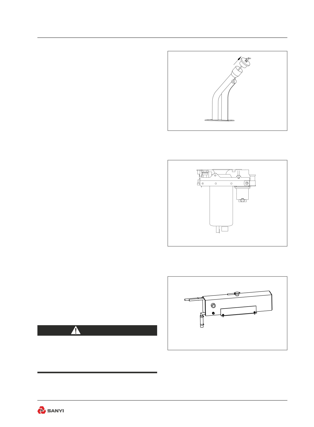
1. Engine
With the engine off, check oil level. The oil
level should be between the lower and upper
marks on the dipstick. Add oil if low (see Fig
4-2).
Fig 4.2
2. Fuel filters
Drain sediment and water from sump until fuel
runs clear (see Fig 4-3).
Fig 4.3
3.Radiator header tank
Check coolant level. Add if low. (see Fig 4-4).
In subfreezing temperatures, be sure that the
coolant contains sufficient antifreeze.
WARNING
Press button in centre of cap to
bleed pressure before removing cap
Fig 4.4
completely. Fill to bottom of filler neck.
4-3
Operating the Truck
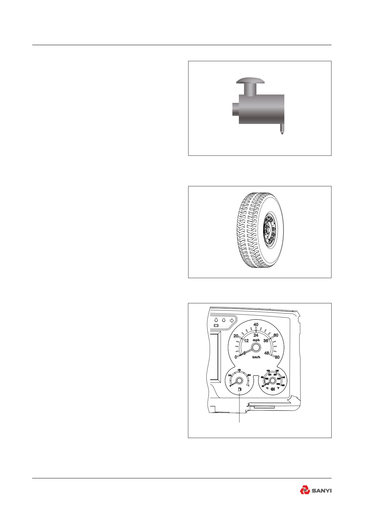
4. Air Cleaner vacuator valve(s)
Check for proper operation. Clean if Required
(see Fig 4-5).
Fig 4.5
5. Tyres
Carefully inspect all tyres for cuts, bruises,
or other damage and proper inflation for the
loads to be carried. Inflate all tyres to the
recommended pressure while cold (see Fig
4-6).
Fig 4.6
!
6. Fuel level gauge
Check fuel level. Tank should be filled at end
of each shift to prevent condensation(see Fig
4-7).
Fuel gauge
Fig 4.7
4-4
Operating the Truck
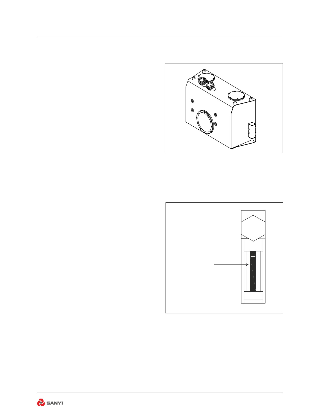
7. Body and disc brake cooling tank - cold
oil level
The bottom sight gauge should show full. Add
fluid, if low (see Fig 4-8)
8. Steering and braking tank - cold oil level
With the engine off, turn the steering wheel
back and forth to dissipate any pressure in the
steering accumulator. Oil should be showing in
the middle sight gauge. Add fluid, if low (see
Fig 4-8).
Fig 4.8
9. Transmission - cold oil level
This check is made only to determine if the
transmission contains sufficient oil for safe
starting. Make sure there is some oil showing
on the sight gauge before starting the engine.
Add oil if low (see Fig 4-9).
Oil level
Fig 4.9
4-5
Operating the Truck
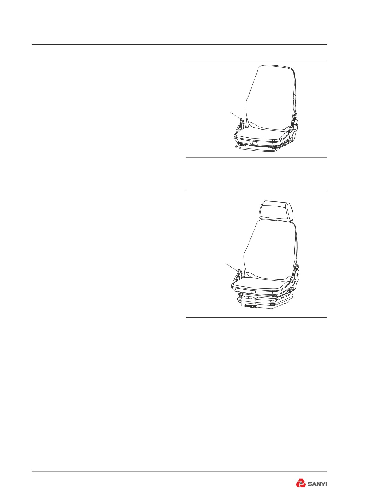
10. Seat and seat belts
Adjust the seat position and lap belt as
required to allow complete machine control at
all times with minimum fatigue. Make sure the
seat belt does not restrict movement for proper
safety belt
machine operation (see Fig 4-10 and 4-11).
Fig 4.10
safety belt
Fig 4.11
4.3 Engine Operation
Note: The electronic controlled engine will
override the electronic foot pedal position
until the engine is warmed up to the correct
operating temperature. The engine MUST
be started with foot 'OFF' the electronic foot
pedal.
Do not place engine under FULL LOAD at
FULL SPEED IMMEDIATELY after starting.
ALWAYS allow the engine to fully circulate
lubricant and warm up gradually before
operating at full speed and full load.
Operate engine at top rated speed when
maximum power is needed for the load.
4-6
Operating the Truck
NEVER idle the engine more than 5 minutes
at a time; shut it off.
If any gauge operates outwith its normal
operating range or a warning indicator
illuminates, shut engine down immediately and
report to service or maintenance personnel.
Turn off the engine if the “stop”, “warning”,
and “maintenance” indicators are lighted
simultaneously when the engine is working,
and the engine state indicator in display is red
at the same time.clear the fault following the"
Charpter 3 of this manual -----Operation of
Electronic-Control Fuel System "
WARNING
Never start the engine indoors unless
proper exhaust ventilation is provided
to remove deadly exhaust gases.
Once the engine is running, move the
machine outdoors as soon as possible.
Exhaust gases are hazardous and can
cause unconsciousness and death.
Operating the engine beyond high
idle speed can cause severe engine
damage. The engine speed must
not exceed 2400 rev/min under any
circumstances. When descending
a steep grade, use a combination
of transmission gears, retarder and
service brakes to control the vehicle
and engine speed.
4-7
Operating the Truck
4.4 Start the Engine
Attention to the warning indicators and
instruments when starting the engine, and
operating, will help the operator monitor the
machine systems and components.
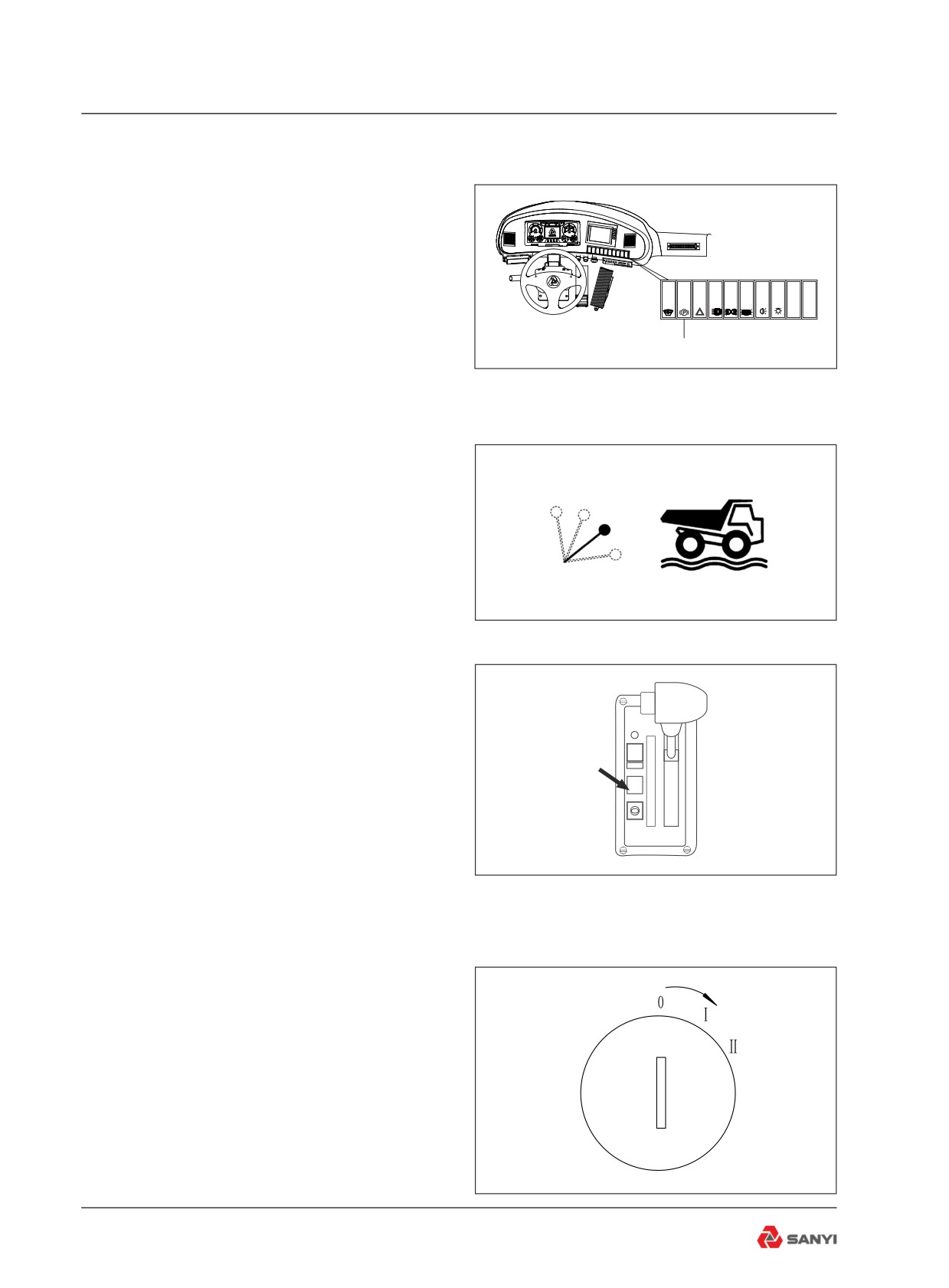
1. Make sure the parking brake switch is in the
P
'PARK' position.(see Fig 4-12).
parking brake switch
Fig 4.12
2.Make sure the body control lever is in the
'FLOAT' position.(see Fig 4-13).
Fig 4.13
3. Make sure the transmission shift selector is
in the 'NEUTRAL' position.(see Fig 4-14).
R
MODE
N
D
5
N
4
3
2
1
Fig 4.14
4. Insert Ignition key and turn clockwise to
position 'I'.(see Fig 4-15).
Fig 4.15
4-8
Operating the Truck
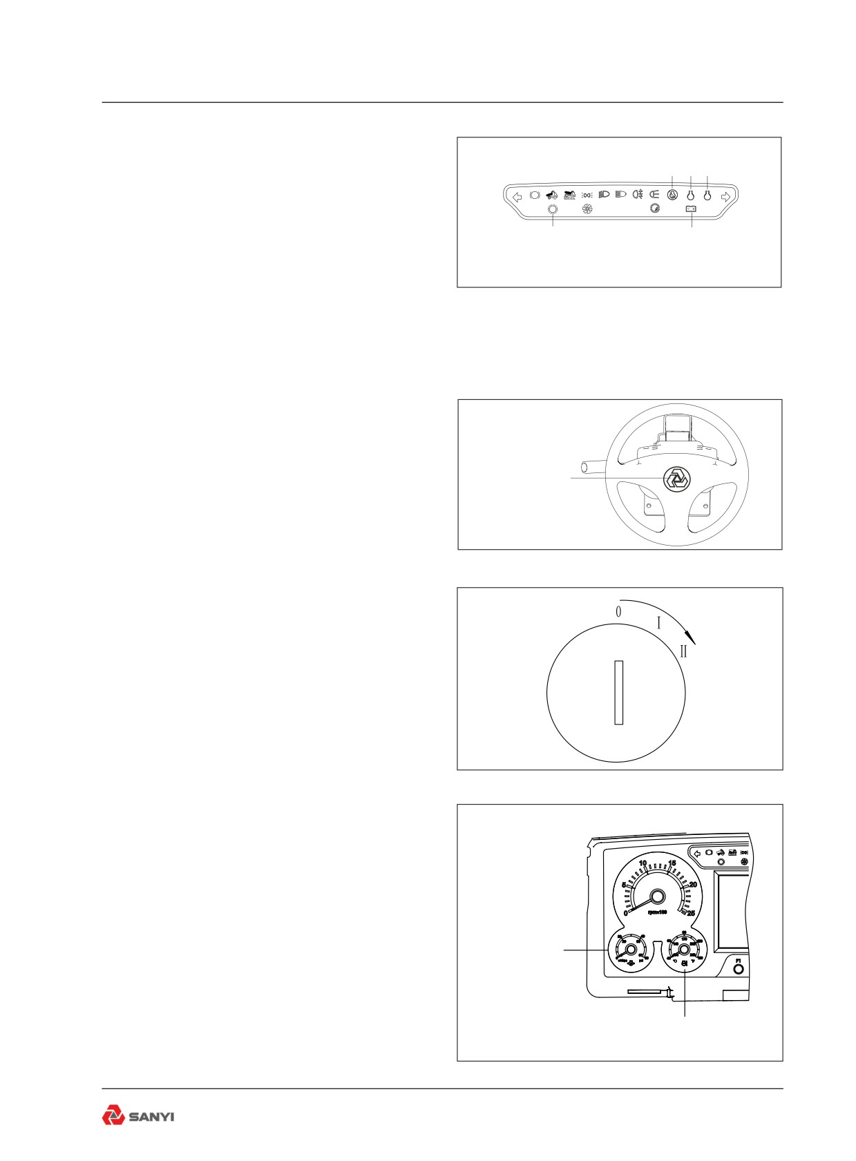
5. Check the instrument panel; the engine
“maintenance”, “warning”, and “stop” indicators
1
2
3
shall flash for several seconds and then
P
!
!
extinguish; the “Alternator Charging” and
“transmission fault” indicators shall be
4
5
constantly on; “transmission state” indicator
show red, “engine state” and “vehicle monitor
system state” indicators show green, no
Fig 4.16
buzzer alarm (see Fig4-16).
1.Engine stop indicator
2.Engine maintenance indicator
3.Engine warning indicator
4.Transmission fault indicator
5.Alternator charging indicator
Horn contorl
6. Press horn control to sound horn. (see Fig
4-17).
Caution:Always sound horn before starting
Fig 4.17
engine or operating anycontrol.
7. Turn key further clockwise against spring
pressure to position 'II' to crank the engine.
Release the key as soon asthe engine starts
firing.
Caution: Never crank the engine more than
30 seconds continuously. Allowstarter(s) at
least 2 minutes cooling time between cranking
periods to avoid overheating. (see Fig4-18).
Fig 4.18
8.Check the engine oil pressure gauge. Within
10 to 15 seconds at engine idle,the gauge
P
needle should rise into the white zone. If the
!
needle does not rise within 15 seconds, shut
off the engine and do not operate until the fault
is identified and corrected. (see Fig 4-19).
Engine pressure
gauge
9. Observe the engine water temperature
gauge. After a few minutes running time at
moderate load and varying speed, the gauge
Engine water temperature gauge
needle should be in the white zone. If the
needle moves into the red zone, the engine
Fig 4.19
is over heated and should be shut down
4-9
Operating the Truck
immediately.(see Fig 4-19).
4.5 Starting the Engine with
Jumper Cables
Caution: Be sure machines are not touching
each other. Use cables that are equal to cable
size on the machine.
If jumper cables are used to start an engine,
be sure to follow this procedure:
Connect one end of a jumper cable, usually
coloured red, to the discharged battery
'POSITIVE' (+) post. Connect the other end of
the same cable to the 'POSITIVE' (+) post on
the booster or charged battery.
Connect one end of the second cable, usually
coloured black, to the 'NEGATIVE' (-) post of
the booster battery. Connect the other end of
the 'NEGATIVE' (-) cable to machine frame.
WARNING
Hazardous hydrogen gas and
sulphuric acid. Check for required
voltage and polarity connections
to discharged batteries. Excessive
booster voltage and/or incorrect
jumper cable connections, open flame,
lighted cigar, or other ignition source
can cause battery explosion/fire. Keep
all sources of ignition away from
batteries. Do not lean over batteries,
and wear eye protection at all times to
prevent personal injury.
Do not jump start a vehicle by using
arc welding equipment. Currents and
voltages are dangerously high and
cannot be sufficiently reduced to make
the method safe.
4-10
Operating the Truck
4.6 Pre-Operating Checks
Make sure all cab glass, mirrors and lights
are clean. Test all controls to ensure they
are functioning properly. Select 'REVERSE'
momentarily on the transmission shift selector
to make sure the reverse alarm sounds.
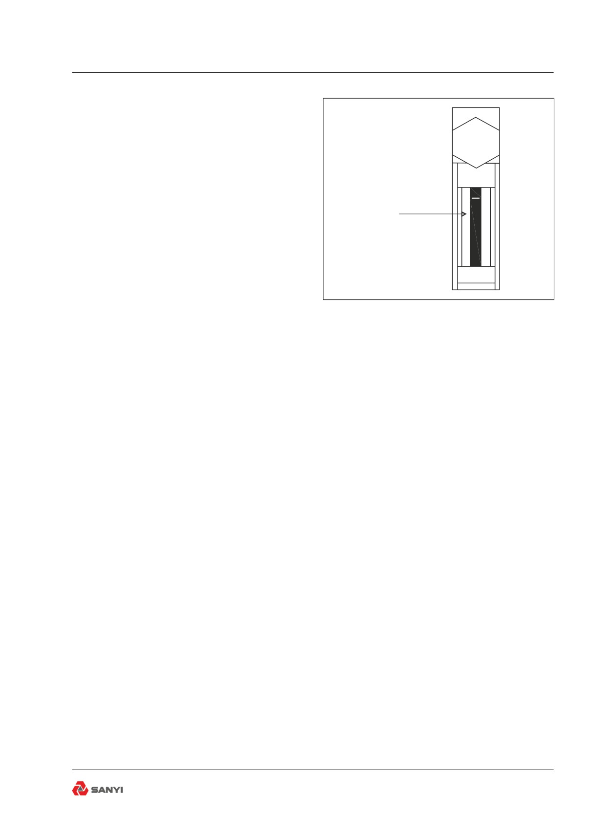
1. Transmission - Hot Oil Level - The parking
Oil level
brake must be applied and the road wheels
securely blocked while carrying out this
check. With the engine idling, transmission
in 'NEUTRAL' and at normal operating
temperature, the top of the oil column should
be visible in the sight gauge. Add oil if low. If
Fig 4.20
the top of the column is above the sight gauge,
the transmission is overfull and oil should be
drained.
2. Body and Rear Brake Cooling Hydraulic
Tank - Hot Oil Level - Operate the body hoist
cylinders to their fully-extended positions to
charge all cylinders and lines then lower the
body. With the engine running, and body fully
lowered, the oil level should show in the top
sight gauge. Add oil if low. Under all conditions
the bottom sight gauge should show full.
3. Steering and Braking Hydraulic Tank -
Hot Oil Level - With the engine running, oil
at operating temperature and accumulators
charged, oil must be between the top and
middle sight gauges. Shut down the engine
and operate the steering left and right to
discharge steering accumulator. Operate
treadle valve continuously to discharge
braking accumulators. Oil should show in the
top sight gauge.
4-11
Operating the Truck
4.7 Braking Function Check
Determination the function of the braking
system before the working each times for
safety !
Caution:The following checks are NOT
intended to measure maximum brake holding
ability. If NEW brake pads are fitted, they
MUST be burnished as per the manufacturers
recommendations before carrying out the
checks.
WARNING
Make sure the surrounding area of
truck is free of person and barrier
before checking brake function.
If the truck moves during these
checks, the operator shall stop, use
the parking brake and don't operate
again until all of fault are corrected .
4.8 Service Brake Performance
Check
Following the methods and sequence at below
for checking:
1. Depress the foot brake pedal;
2. Select 1st gear on the transmission shift
selector;
3. Release parking brake;
4. Depress the accelerator pedal.
Inspection,the machine should not move
before engine speed increased to 1350 r/min.
following sequence as below when the
checking has been finish:
1. Decelerate the engine;
2. Shift transmission to NEUTRAL brake;
3. Apply the parking brake;
4. Release the service brake pedal.
4-12
Operating the Truck
4.9 Emergency Brake
Performance Check
Following the methods and sequence at below
for checking in sequence :
1. Depress the service brake pedal;
2. Release emergency brake;
3. Select 1st gear on the transmission shift
selector;
4. Apply emergency brake;
5. Release service brake pedal;
6. Depress the accelerator pedal,
Inspection,the machine should not move
before engine speed increased to 1350 r/min.
Then, decelerate the engine and select 1st
gear on the transmission shift selector.
Caution:
1. Brake holding effort required to hold a
machine static at a specific engine speed,
can vary from machine to machine due to
differences in engine performance, power train
efficiency, etc., as well as differences in brake
holding ability.
2. As an indication of system deterioration,
the engine speed at which point the machine
moved, with the service or emergency brakes
applied, can be compared against the engine
speed your machine was able to hold to on a
previous check.
4.10 Driving and Stopping
Before driving off observe all instruments and
warning indicators. All instruments should
operate in their normal range and all warning
indicators should be out except possibly the
Direction Indicator and Headlight Main Beam
warning indicators.
Make sure the area around the machine is
clear of personnel and obstructions before
driving off.
In the first few minutes of travel, check
carefully for the required steering, braking,
engine and transmission power response for
4-13
Operating the Truck
maximum operating safety.
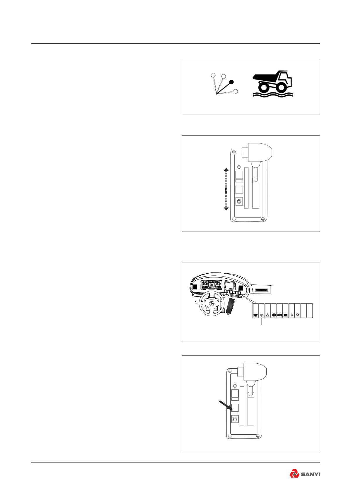
1. Make sure the body is fully down and body
control lever is in the 'FLOAT' position.(see
Figure 4-21)
2. Apply the service brake and release the
parking brake.
3. Select the driving direction and the required
Fig 4.21
range.(see Figure 4-22)
4. Sound horn; two blasts for forward and
three blasts for reverse.
5. Release the service brake, apply the
accelerator and move off.
R
6. To stop the machine release the accelerator
MODE
N
D
and depress the service brake pedal. Release
5
the service brake as the machine slows until,
3
4
3
when stopped, the pedal is depressed just
2
1
enough to hold the machine stationary. The
retarder brake is recommended to decelerate
the truck unless the truck must be stopped
immediately.
Fig 4.22
7. When the machine has stopped, shift the
transmission to Neutral, apply the parking
brake and release the service brake.
8.If the service brake does not stop the
machine. Apply the emergency brake. This
should only be applied to stop the machine in
an emergency.
P
4.11 Stopping the Engine
parking brake switch
1. Make sure the rocker switch is in the 'PARK'
position. (see Fig4-23).
Fig 4.23
R
2. Make sure the transmission is in
MODE
N
D
'NEUTRAL'.(see Fig 4-24).
5
N
4
3. Allow the engine to idle 3 - 5 minutes after
3
2
a full load operation before shutting it off.
1
This allows the engine to cool gradually and
uniformly.
Fig 4.24
4-14
Operating the Truck
WARNING
There is no mechanical connection
between the engine and wheels
on machines with converter
transmissions. The parking brake must
always be applied when the engine is
switched off.
4. Turn the steering wheel in both directions
to dissipate the pressure in the steering
accumulator to prevent accidental steering
during bleed down.(see Fig 4-25).
Fig 4.25
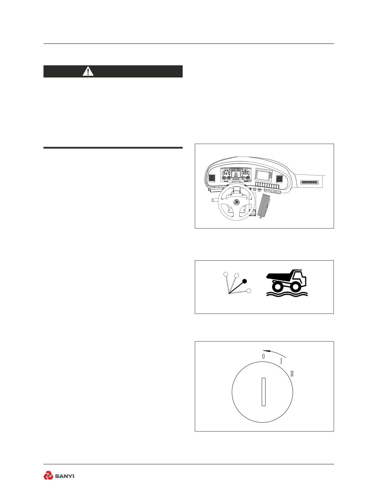
5. Make sure the body control lever is in the
'FLOAT' position. (see Fig 4-26).
Fig 4.26
6. Turn the ignition key switch to the 'OFF'
position ('0'). (see Fig 4-27).
Fig 4.27
4-15
Operating the Truck
4.12 Parking
When parking the machine overnight, or for
an extended period, the following procedure in
addition to that given in 'Stopping the Engine'
will help maintain it in good condition for
subsequent use:
1. Fill the fuel tank completely, to prevent
condensation. If security kit is supplied, keep it
locked.
2. Always park the machine on level ground
where possible. If the machine must be
parked on a grade, position the machine at
right angles to the grade and block the wheels
securely.
3. If below freezing temperatures are
expected, make sure the cooling system has
sufficient antifreeze to prevent the coolant
freezing. If antifreeze cannot be added to
the cooling system, drain the cooling system
completely.
Check all tyres, hoses, wiring, tubing and
fittings for cuts, ply separation, abrasion,
fraying, or other damage or deterioration.
Inspect for structural damage to the cab,
body and chassis. Attach warning signs to the
steering wheel or to a control to alert others if
lubricant has been drained, batteries removed
etc.
4.13 Prolonged Storage
Turn the circuit breaker beside battery to
“shutoff” position to prevent battery leakage
when removing CEC memory and radio power
supply.
Retune the radio if the circuit breaker is set
again.
Note: The code in CEC memory may be lost
after the power supply is disconnected.
4-16
Working the Truck
5 WORKING THE TRUCK
5.1 Working the Truck
Mining Dump trucks are used on a variety of
hauling jobs, from mine overburden removal
to dam building. Every truck operation,
regardless of the type of job, can be divided
Keep the dump
into four phases; loading, hauling, dumping
truck static
and the empty return.
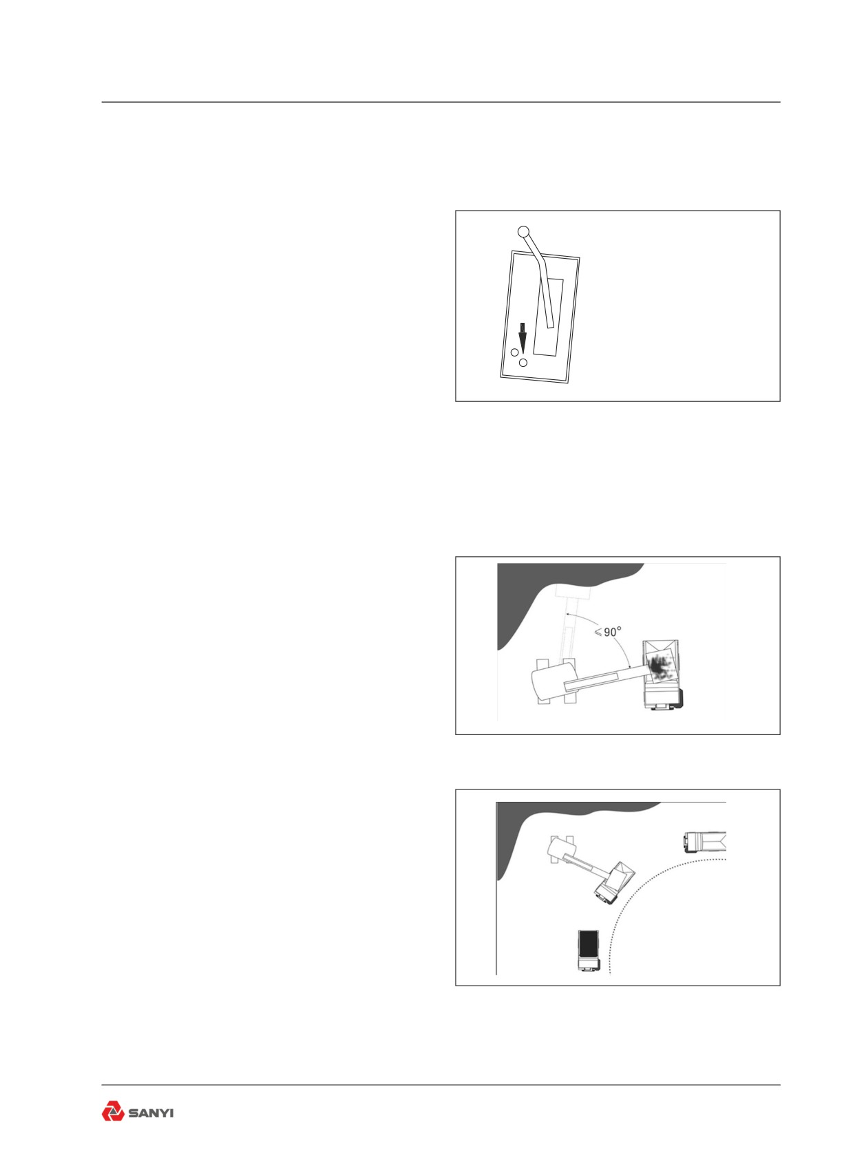
Note: After coming to a stop for loading or
unloading the truck, the Parking-Emergency
Brake control can be pushed in to hold the
Fig 5.1
brakes in the applied position as though the
foot brake is depressed. (see Fig 5-1).
5.2 Loading
The most common methods of loading trucks
are with hydraulic excavators, rope shovels,
and front end loaders. For maximum material
movement, the truck operator must help the
loading machine operator hold loading time to
a minimum. The fewer manoeuvres the truck
must make to get into loading position, the
sooner loading can start. And the shorter the
distance the loading unit bucket must travel
between the cut, or stockpile and the truck
body, the more passes it can make in a given
Fig 5.2
period of time and the quicker the truck can be
loaded.
Fig 5.3
5-1
Working the Truck
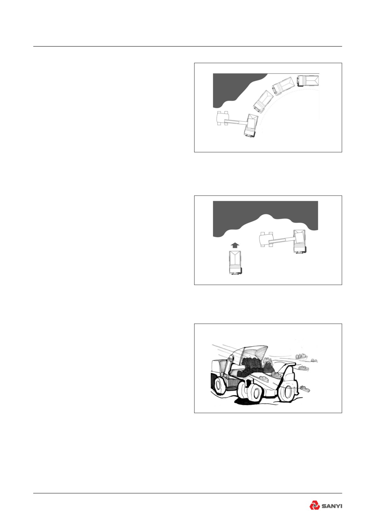
Ideally, the hydraulic excavator or rope shovel
should require 90o or less swing to dump
into the truck body for best loading efficiency.
Required turning and backing to position the
truck for loading should be held to a minimum.
A common loading method is to have trucks
travel a semicircle in the loading area. This
Dump truck space
method eliminates all backing. Waiting
is the length of two
machines should stay about two truck lengths
dump trucks
behind the one being loaded to avoid any
Fig 5.4
spillage from the loading machine bucket or
truck body. The operator of the waiting truck is
also better able to judge the best spot for his
truck when it is his turn to be loaded(refer to
fig.5-4).
On some jobs, the loading machine might work
most efficiently when trucks are positioned
on both sides of the loader. Thus, while one
truck is being loaded, another can move into
position on the opposite side of the loader
and the loading machine can swing over to
Two-side loading
load the next truck with a minimum of lost
time. Since the truck is usually backed into the
Fig 5.5
loading position with this method, the operator
must be alert and careful while backing(refer
to fig.5-5).
For fastest, most accurate loading when
being loaded by a front end loader, the truck
operator should spot his machine on the most
level area and at an angle to the face of the
bank or stockpile. This minimizes loader travel
time, particularly with a raised, full bucket.
Where possible, the truck should also locate
downwind of the loader when dusty-type
material is being loaded on a windy day. This
practice improves both working conditions and
visibility for the loader operator(refer to fig.5-
Fig 5.6
6).
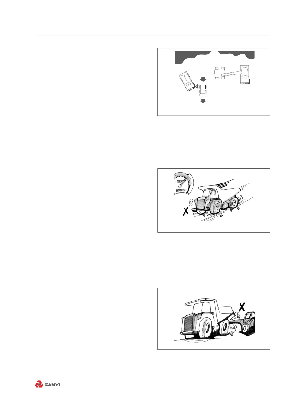
A cleanup dozer or small loader is often
working in conjunction with the main loading
machine to keep the area clear of bucket
spillage for maximum efficiency of the loading
operation. The truck operator must always be
alert to the position of the cleanup machine
5-2
Working the Truck
when entering the loading area to avoid
congestion, and for maximum safety(fig.5-7).
The following precautions should be observed
when approaching the loading area and while
being loaded.
Avoid rocks and other shovel spillage that
can needlessly damage tyres or other truck
components. Allow the cleanup machine
Take care of other
sufficient time to clear up such debris.
trucks
Do not move the truck into loading position
Fig 5.7
with the shovel bucket swinging overhead.
Large rocks that might fall from the bucket can
be dangerous to both the truck and operator.
Keep your head and arms inside the cab
during loading to avoid the danger of falling
rocks or other shovel spillage.
When the loader operator signals that the
truck is loaded, sound two blasts on the horn,
release the brakes and shift the transmission
to drive (D). Move out of the loading area
and onto the haul road with the least possible
delay to allow any waiting truck to move into
the loading position as soon as possible(refer
to fig.5-8).
Fig 5.8
5.3 Hauling
While travelling the haul road, always maintain
a safe speed for the haul road conditions and
grades. Never allow the machine to move or
coast with the transmission in 'NEUTRAL'!
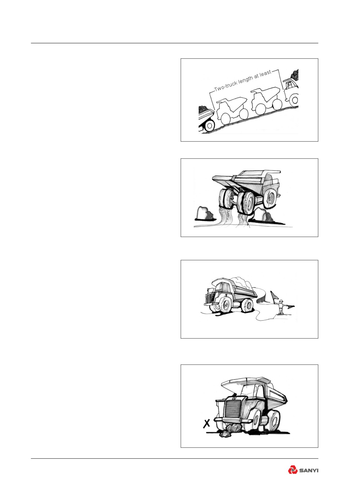
When approaching downgrades, select
the proper transmission range and use the
retarder and service brakes as required to
maintain safe descent speed without over-
speeding the engine or gaining excess travel
speed. Generally, the transmission range
required for ascending is also correct for
descending a grade(refer to fig.5-9).
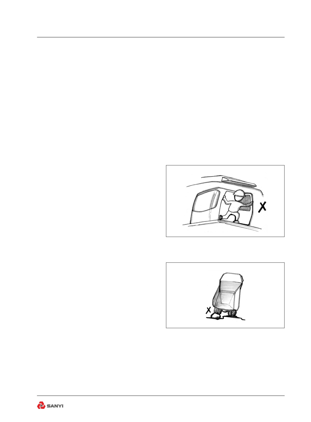
Always remain a safe distance behind the
machine ahead, particularly on downgrades.
Fig 5.9
A good rule-of-thumb to follow is to allow two
(2) truck-lengths between machines for each
15 km/h (10 mile/h) of travel speed under
5-3
Working the Truck
normal operating conditions. Under adverse
conditions, allow more room for safe operation.
On jobs on which minimum distance between
machines is specified for the haul road, be
sure to observe the regulations at all times.
Such regulations would be established for the
safety of everyone on the job(refer to fig.5-10).
Safety first
Pay attention to haul road conditions to
avoid rocks, holes, or other obstacles. Such
obstacles not only present hazards to safe
Fig 5.10
operation, but can needlessly damage tyres
and rides if not avoided(refer to fig.5-11).
Be sure to reduce speed and come to a full
stop, as required, at intersections, rail-roads,
public highways etc.. Where a 'FLAGMAN' is
stationed to direct traffic, always stay alert and
follow his directions.
5.4 Dumping
Fig 5.11
The dumping operation usually depends upon
the type of material being hauled. For instance,
overburden and other waste material is usually
dumped over a spoil bank or piled into large
mounds. The dumping on a job of this type
might be controlled by a dump 'SPOTTER',
'FLAGMAN' or 'BANKSMAN' or second person
who directs the truck to its dumping area. The
'SPOTTER' is needed due to the limited rear
visibility the operator has with a loaded truck of
this size. While backing to dump, the operator
must watch the 'SPOTTER' at all times and
Fig 5.12
follow his direction. Under no circumstances
should the operator leave his seat to gain
better visibility while backing(refer to fig.5-12).
Always remain seated to maintain maximum
machine control(refer to fig.5-13).
Mineral ores, blasted rock etc., are usually
dumped into a hopper or crusher where it is
processed before shipment. When dumping
into a hopper, the operator, in order to
avoid excess wear on the tyres, must avoid
hitting the protecting rail at the hopper. If a
DRIVEOVER HOPPER is used, the operator
Fig 5.13
5-4
Working the Truck
must avoid rubbing the tyre inner sidewalls.
When hauling dirt or rock from a borrow pit into
a fill area such as an earth-fill dam, the load
is usually dumped in a string with other loads
and the loads smoothed out with a crawler
tractor. When dumping on a fill of this type,
the operator usually works alone and picks his
own dumping place. To save bulldozer work
and cleaning up, the load should be dumped
as close as possible to the preceding load.
The operator should pull past the preceding
load, turn in line with the string and back his
truck until it is within a few feet of the last load.
This assures that the load will fall in the right
place.
No matter what kind of job the operator is
working, there are a few things which are
common to all jobs and which the operator
should observe. When dumping over a spoil
bank without a 'SPOTTER', know how close
the machine can safely approach the edge
under all weather conditions. If in doubt as to
dumping safety, dump the load a safe distance
from the edge so that it can be pushed over
the edge later(refer to fig.5-14).
Fig 5.14
Before raising the body, make sure the rear
wheels are on firm level ground. If one wheel
is higher than the other, a twisting strain is
imposed upon the body hinge pins, hoists
and chassis. Stop the machine, allow the
engine to slow to idle, shift the transmission
to 'NEUTRAL' and apply the brakes with the
Parking-Emergency Brake control to hold the
machine stationary(refer to fig.5-15).
Push the body control lever back into the
'RAISE' position and accelerate the engine.
Fig 5.15
Decelerate the engine to slow the raising
speed as the hoists approach their maximum
extension. When the body has been raised to
the desired height, release the control lever
into the 'HOLD' position until the body is to be
lowered. Do not hold the lever in the 'RAISE'
position when the hoists are fully extended
to prevent unnecessary hydraulic system
5-5
Working the Truck
relivalve operation.
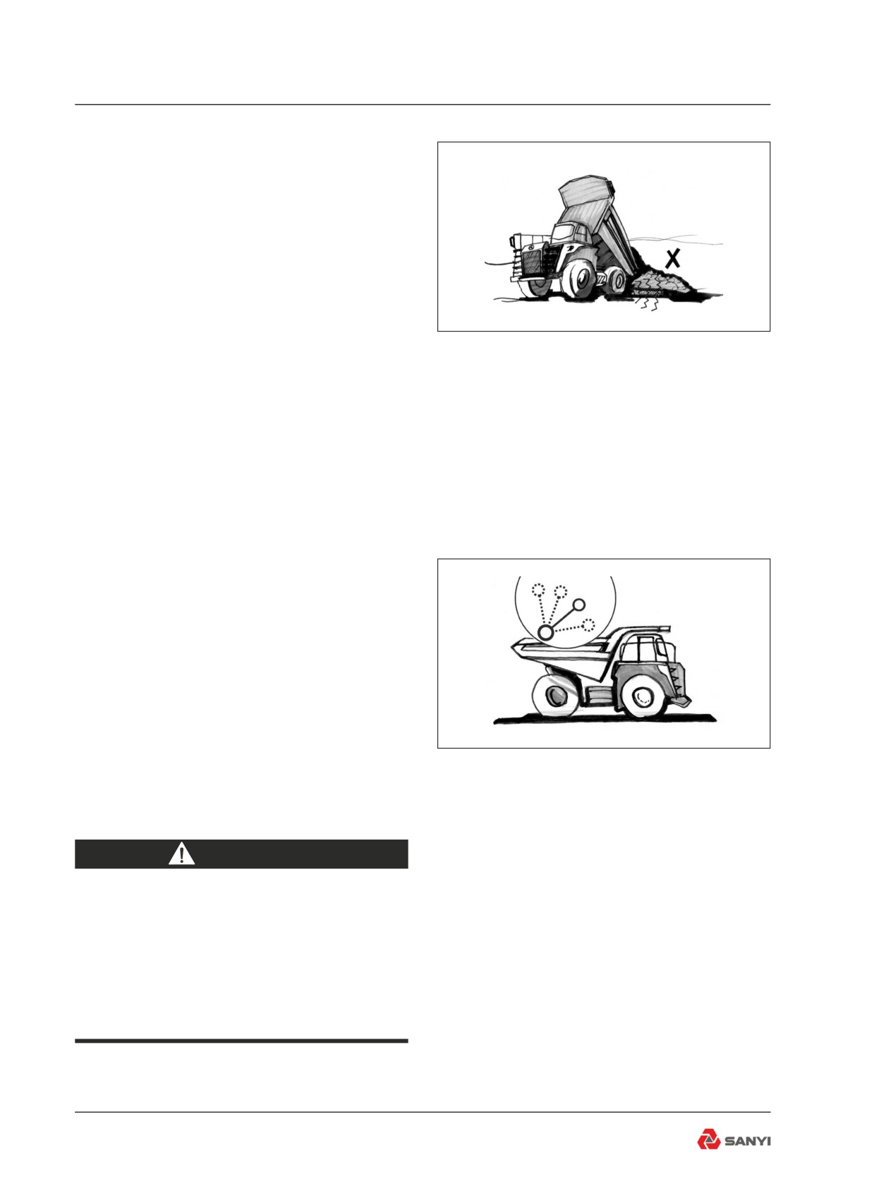
NEVER 'JUMP DUMP' the machine by
bouncing the rear tyres against a stop block,
or otherwise jarring the body in its raised
position to dislodge stuck or frozen material.
The tremendous loads that this practice
develops on the body pin area, chassis
and hydraulic system can cause needless,
extensive stresses. (refer to fig.5-16)
Fig 5.16
Once the load has been dumped, push the
control lever down into the 'FLOAT' position
to allow the body's weight to lower it to the
chassis. If the body does not begin to lower by
its weight, push the control lever down into the
'LOWER' position and power the body down
until it begins to lower by gravity. Then release
the control lever into the 'FLOAT' position.
Note:For the truck running stably that should
be operated the hoisting handle slowly while
the body hoisting period and lowing period.
5.5 Empty Return
Make sure the body is completely lowered, the
body control lever is in the 'FLOAT' position,
and the transmission is shifted to the correct
range before releasing the brakes and moving
away from the dump site.
Fig 5.17
Except for the above, the procedure for
returning empty to the loading area is the
same as that given earlier for 'HAULING'.
WARNING
DO NOT drive the truck with the body
up. Apart from effecting the stability of
the truck, there can be severe danger
from contacting overhead electric
cables, trees, or bridges over the haul
route.
5-6
Roading
6 ROADING
6.1 General
‘ROADING’ (operating a truck over public
highways) requires special care and attention.
Trucks, because of their large size, are
slower and less manoeuvrable than most
other vehicles encountered on the road. Yet,
while on the road, they must be operated for
extended periods of time at or near maximum
speeds.
Before 'ROADING' a truck for an extended
distance between jobs, or between widely
scattered sections of a job, the machine must
be properly equipped and in good condition.
It is also recommended to carry a 'Warning
Triangle'.
The operator must use extra care while on
the public highways and remain constantly
alert, especially for overhead cables and low
bridges.
Necessary permits must be obtained from
the proper authorities before the machine is
'ROADED' on public highways.
6.2 Preparation Prior to Roading
Lubrication
Thoroughly lubricate and service all
components and systems as described under
'LUBRICATION AND SERVICING' in this
handbook and/or service manuals for this
machine.
Inspection
Perform all pre-starting and post-starting
checks described in this Handbook. Pay
particular attention to the function of all
instruments and lights, and make any repairs
necessary.
Note: Improper tyre inflation during over-
the-road operation can cause rapid tyre
deterioration by overheating. Tyre pressures
6-1
Roading
increase with heat. Always check pressures
while tyre is cold. Consult your tyre dealer
for proper pressures and tyre speed limits for
roading.
Note: Make sure the body control lever is
in the 'FLOAT' position. Failure to comply to
this caution could result in overheating the
hydraulic oil and failure of the hydraulic system
components.
Check the inflation pressures of all tyres,
while cold, with an accurate tyre pressure
gauge. Inflate tyres if necessary, while cold, to
the recommended pressure for 'ROADING'.
Inspect all tyres thoroughly and carefully for
stones or other debris embedded in the treads
or carcasses. Inspect for cuts, bruises, burned
beads, abnormal wear and damaged wheels
rims. Replace any damaged or excessively
worn tyres.
Check all hoses, drain cocks, fuel level check
cocks, and other potential sources of leaks.
Make sure that all leaks are repaired and that
all drain cocks are sufficiently tightened to
avoid subsequent loosening. Make sure that
all warning flags, oversize load signs etc. are
in place and secure.
Clean all glass and adjust the seat for proper
operation of all controls.
Check all lights and other controls for proper
operation.
Make sure the truck body is empty, fully
lowered and the body control lever is in the
'FLOAT' position.
6.3 In Case of Trouble
If trouble develops en route, move machine
off the road at the first safe parking place, and
shut off the engine. Carefully note as many
of the symptoms of the trouble as possible,
such as rough engine operation with loss
of power and overheating, or, loss of speed
and transmission clutch pressure with normal
engine operation etc.
6-2
Roading
If the area in which the trouble occurs requires
that the machine be left unattended while the
trouble is reported by phone, disconnect a
battery cable and apply security locks, if so
equipped, before leaving the parked machine.
Make sure body is completely lowered and the
parking brake is applied. Report the following
data as soon as possible.
1. Exact location.
2. Destination.
3. The nature of the trouble (with as many
details as possible) and the time and
conditions under which it happened.
4. The telephone number at which the
machine operator can be reached.
Note: Do not attempt to restart or operate the
machine unless instructed to do so. An engine,
pump, transmission or other component that
develops a minor defect can be completely
destroyed in just a few extra minutes of
unnecessary operation.
6-3
Roading
6-4
Moving Disabled Truck
7 MOVING DISABLED TRUCK
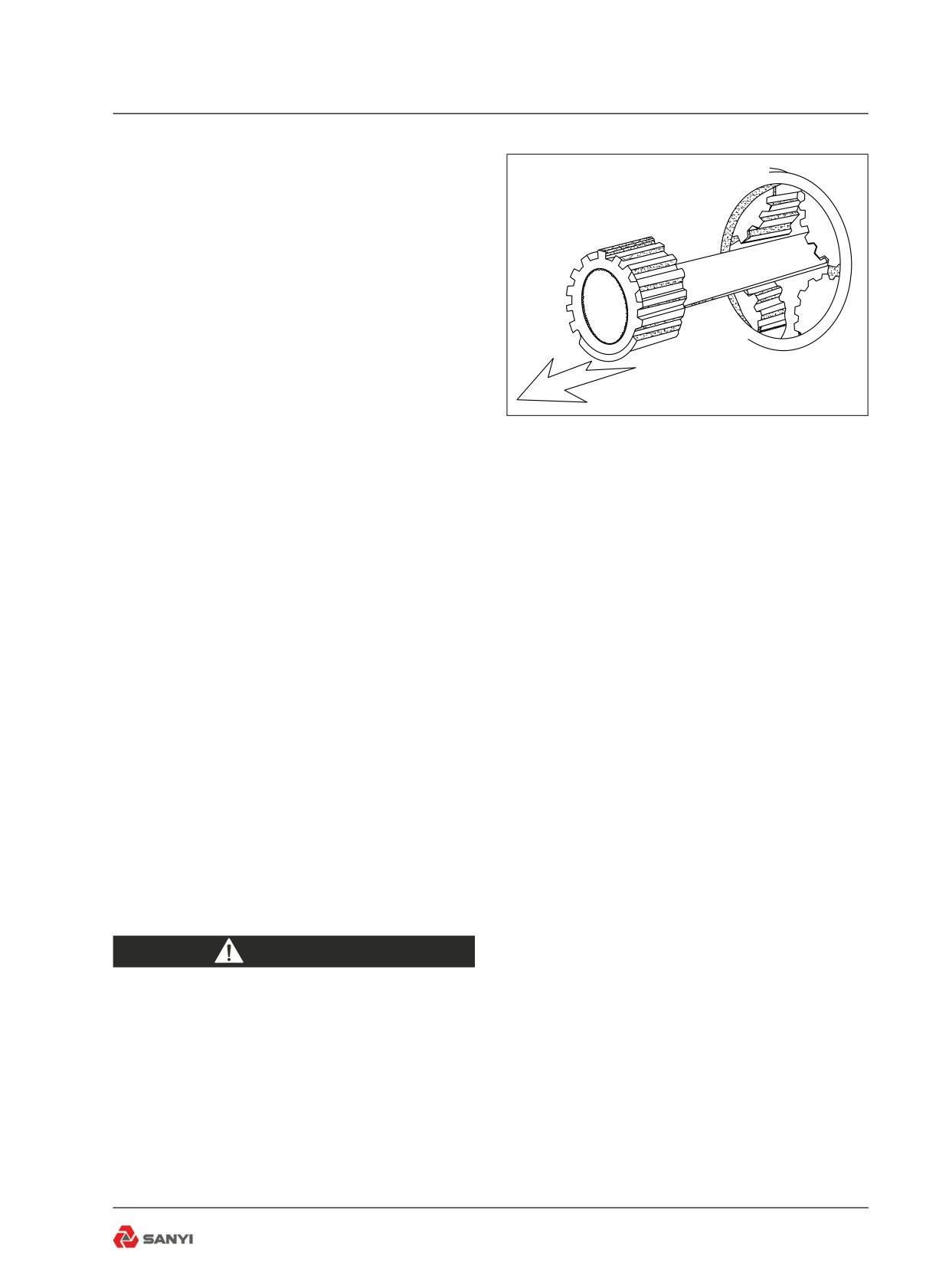
7.1 Moving Disabled Truck
Any unusual power train noises noted while
operating the truck should be reported to
those responsible for maintenance. Should
the power train, hydraulic or electrical systems
fail, the machine should be stopped and shut
down immediately until suitable repairs can
be made. If the failure is in the power train
and the truck must be moved to a service
Fig 7.1
area or workshop to make required repairs,
remove the drive flange covers from the drive
wheels and pull the axle shafts and final
drive planetary sun gears from the planetary
assemblies. This will prevent any possible
additional damage, which may be caused by
the drive wheels turning the power train as the
machine is towed. Replace the covers on the
drive wheels to retain lubricant and prevent
entry of dirt(refer to fig.7-1).
If possible, start the engine to provide the
required hydraulic pressure for steering and
braking. Never allow riders on a machine
being towed without sufficient hydraulic
pressure for safe steering and braking.
If the nature of the trouble prevents engine
operation, repairs must be made on the site of
the breakdown, or special arrangements made
for towing the machine safely to the repair
area without steering and braking power.
WARNING
Uncontrolled machine movement
hazard. There is no mechanical
connection between the machine
wheels and the engine when the
parking brake is released. Before
releasing the parking brake, make sure
the machine wheels are secured with
chock-blocks to prevent or restrict
unexpected machine movement. When
7-1
Moving Disabled Truck
moving the machine with insufficient
hydraulic pressure and power for safe
steering and braking, use extreme
caution to ensure personnel and
property safety.
Connect a suitable towing bar to one of the
lugs on the front bumper of the disabled
machine and reverse another machine, in a
straight and in-line manoeuvre, towards the
disabled machine. Connect the opposite end
of the towing bar to the towing point on the
rear axle of the recovery machine and ensure
that it is securely locked.
Note: An alternative method of towing a
disabled machine is by connecting an A-Frame
arrangement to the lugs on the front bumper
of the disabled machine and the towing point
of the recovery machine.
To prevent possible damage to the
transmission, the towing speed should never
exceed 10 km/h (6.2 mile/h) and the distance
towed should not be longer than 10 km (6.2
miles).
WARNING
If using a chain or cable, be sure it is
strong enough for the expected load
and properly secured.
When pulling, take up the slack slowly
to avoid jerking. A chain or cable which
fails under load can cause serious
injury. Stand clear. Do not pull through
a kinked chain or cable. Do not pull or
tow unless the operator’s compartment
is guarded against or out of reach of a
whipping chain or cable. Attach only
to the towing points. Failure to follow
these instructions could cause serious
injury or death.
7-2
Lubrication and Servicing
8 LUBRICATION AND
SERVICING
8.1 Safety Precautions
Do not allow unauthorized personnel to
service or maintain this truck. Study the
Operator’s Handbook and Maintenance
Manual before starting, operating or servicing
this truck. Always follow procedures and safety
precautions detailed in the Service Manual.
Always attach a 'DO NOT OPERATE' or
similar warning sign to ignition switch or a
control before cleaning, lubricating or servicing
the truck. Never allow anyone to work on the
truck while it is moving. Make sure no one is
on the truck before working on it. Do not work
under or near an unblocked or unsupported
body. Always use the body safety pins. Do
not work under or near any unblocked or
unsupported linkage, part or truck.
Always relieve pressure before servicing any
pressurized system. Follow the procedures
and safety precautions detailed in the
Maintenance Manual. Always shut down the
engine according to the procedure under
'Stopping The Engine', described on page 4-11,
before cleaning, lubricating or servicing the
truck, except as called for in this Handbook or
the Maintenance Manual.
When changing oil in the engine, transmission
and hydraulic systems, or removing hydraulic
lines, remember that the oil may be hot and
can cause burns to unprotected skin. When
working on or around exhaust components,
remember that the components may be hot
and can cause burns to unprotected skin.
Always deflate the tyre before attempting to
remove any embedded objects or removing
the tyre and rim assembly from the truck.
Always use a self-attaching chuck with a long
airline, and, stand to one side while the tyre
is inflating. Refer to 4.11 in the Maintenance
Manual.
8-1
Lubrication and Servicing
8.2 Lubrication and Maintenance
Lubrication
Lubrication is an essential part of preventive
maintenance. It is important that the
instructions, regarding types of lubricants and
the frequency of their application, be followed
to prolong the useful life of the truck. Periodic
lubrication of moving parts reduces to a
minimum the possibility of mechanical failures.
WARNING
These trucks s are equipped with
engine and transmission oil pans
which permit operation on longitudinal
slopes up to 30° (60%). For operation
on steeper slopes, the factory should
be consulted.
All change and service periods are
recommendations based on average operating
conditions. Lubricants showing evidence of
excessive heat, oxidation or dirt should be
changed more frequently to prevent these
conditions.
Lubricant change and service periods must
be established on the basis of individual
job conditions utilizing oil sampling and
recommendations from lubricant suppliers.
Thoroughly clean all fittings, caps, plugs etc.,
to prevent dirt from entering any system while
carrying out servicing procedures. Lubricants
must be at operating temperature when
draining.
Note: Do not operate any system unless oil
level is within the recommended operating
levels as indicated on oil level dipstick, sight
gauge or level plug.
8-2
Lubrication and Servicing
7
20
21 10
25 8 10
11 21
19
22
24
13
18
9 14
27
27
27
26
5
26
28
1
23
20
8
25 10 11 11
4
2
3
12 15
21 17 13
Fig 8.1
8-3

Lubrication and Servicing
Lubrication and Service Chart
Interval
Ref.
No. of
Identification
Service Instructions
Lubricant
Service/Quantities
hours
Points
Points
Check oil level. Add
10
1
Engine
1
EO
As Required
if low.
Check oil level. Add
2
Transmission
1
HTF
As Required
if low.
Hoisting/Cooling
Check oil level. Add
3
-
HO
As Required
hydraulic tank
if low.
Steering/Braking
Check oil level. Add
4
-
HO
As Required
hydraulic tank
if low.
Check coolant level.
Refer to 'Remote Water
5
Expansion tank
1
Antifreeze
Add if low.
Tank'
Cooling fan of the
Visually inspect for
7
1
-
-
engine
debris and damage
Visually inspect all
Refer to the Engine
-
Belt
-
-
belts
Manual
Refer to 'Front
Front & rear
Visually inspect
8&9
-
-
Suspension Cylinder' and
suspension cylinders
heights
'Rear Suspension System'
Refer to the label
Mechanical air
Check. Replace
-
1
-
'Requirements for Air
resistance indicator
element if reqd.
Filter Maintenance'
Air cleaner vacuator
Check for proper
-
1
-
-
valve
operation
Oil-water separator for
-
Discharge water
1
-
-
engine fuel
Refer to 'Front Wheel
Check condition.
Assembly' and 'Rear
-
Tyre
Check pressures
6
-
Wheel Assembly' in the
when tyres are cold.
Maintenance Manual
Controls, instruments
Check for proper
-
-
-
-
and warning indicators
operation.
Check for leaks
and worn/damaged
-
General Inspection
parts.
-
-
-
Repair/replace as
required.
8-4
Lubrication and Servicing
Check. Replace
30
Steering oil return filter
-
-
-
element if reqd.
10
Check. Replace
35
Steering pipeline filter
-
-
-
element if reqd.
Front suspension
8
Lubrication
2
EP,NLGI
cylinder bearing
Rear suspension
9
Lubrication
4
EP,NLGI
cylinder bearing
Steering cylinder
10
Lubrication
4
EP,NLGI
bearing
Steering tie rod
11
Lubrication
4
EP,NLGI
bearing
A frame spherical
12
Lubrication
1
EP,NLGI
50
bearing
Transverse stabilizer
13
Lubrication
2
EP,NLGI
spherical bearing
14
Body hinge pin
Lubrication
2
EP,NLGI
Hoisting cylinder
15
Lubrication
4
EP,NLGI
bearing
Front and rear drive
21
Lubrication
6
EP,NLGI
shaft/ spider
27
A arm bearing
Lubrication
6
EP,NLGI
28
Steering crank pin
Lubrication
2
EP,NLGI
1
Engine
Drain and refill
1
EO
-
Refer to the Engine
-
Engine oil flters
Replace filters
2
-
Manual
Refer to the Engine
-
Engine fuel filters
Replace filters
2
-
Manual
Check DCA
Refer to the Engine
250
-
Engine fuel filters
concentration and
-
DCA4
Manual
replenish
Replace filters if
-
Engine coolant filters
1
-
-
required
Engine crankcase
Refer to the Engine
-
Clean
1
-
breather
Manual
7
Engine cooling fan
Check condition
1
-
-
8-5
Lubrication and Servicing
Engine Power Takeoff
16
Check condition
1
EPL
-
(PTO)
Check oil level. Add
18
Wheel planetaries
2
EPL
-
if low.
-
Rear axle breather
Clean
1
EPL
-
-
Transmission breather
Clean
1
-
-
Air conditioning
Check belt tension.
Refer to the Engine
-
1
-
compressor belt
Adjust if required.
Manual
250
Accessory drive belts
Check belt tension.
Refer to the Engine
-
2
-
(if fitted)
Adjust if required.lt
Manual
-
Engine fuel filter
Replace filter
1
-
Clean primary tubes
-
Air cleaner
-
-
-
and inlet screens
-
Front brake disk
Replace
4
-
-
Hydraulic Tank
6
Replace breather
-
-
-
Breather
Clean filler neck
19
Fuel Tank
-
-
-
screen and cap.
Check nitrogen
500
20
Accumulators
-
-
-
pressures.
Steering Column
23
Lube.
2
*EP,NLGI
See note
Universal Joints
Steering Tank
37
Replace breather
-
-
-
Breather
2
Transmission
Discharge and refill
1
HTF
-
Replace filter
-
Transmission cleaner
1
-
-
element
Replace filter
30
Steering oil return filter
-
-
-
element
1000
Hydraulic system
Check pressures at
-
-
-
-
pressure checks
check points
Replace filter
33
Hoisting oil return filter
-
-
-
element
Replace filter
34
Cooling oil return filter
-
-
-
element
8-6
Lubrication and Servicing
Replace filter
35
Steering pipeline filter
-
-
-
element
1000
Replace filter
36
Cooling pipeline filter
-
-
-
element
Engine crankcase
Clean/replace filter
-
1
-
-
filter
element
Drain, clean and
16
Engine PTO
1
EPL
-
1200
refill
Main reducer and
Drain, clean and
17
2
EPL
-
differential assembly
refill
18
Wheel planetaries
Drain and refill
1
EPL
-
Hoisting/Cooling
Wash,clean and
3
-
-
-
hydraulic tank
refill
Steering/braking
Wash,clean and
4
-
-
-
hydraulic tank
refill
Wash,clean and
19
Fuel tank
1
Diesel
-
refill
24
Rear brake packs
Drain and refill
2
HO
-
25
Front wheel bearing
Repack
2
*EP NLGI
-
2000
Drain, flush and
26
Cooling system
-
Antifreeze
-
refill
Replace the filter
29
Steering in-line filter
-
-
-
element
31
Hoisting in-line filter
Wash and replace
-
-
-
32
Cooling in-line filter
Wash and replace
-
-
-
Air conditioning
Drain, flush and
4000
-
1
PAG 100
-
compressor
refill
Fill compartment one half full.
Note - Lubricate slowly until excess lube is
seen.
EO —Engine oil, refer to 'Recommended
Lubricants'.
EPL—Extreme Pressure Gear Lubricant
meeting
specification MIL-L-2105C
HTF—Allison C-4 hydraulic transmission oil,
8-7
Lubrication and Servicing
refer to 'Recommended Lubricants'.
HO—hydraulic transmission oil, refer to
'Recommended Lubricants'.
EP, NLGI — #2 EP lithium base grease, refer
to 'Recommended Lubricants'.
*EP, NLGI—Extreme Pressure Lithium No.
2 Grease(without 'Molybdenum')., refer to
'Recommended Lubricants'.
PAG OIL - Polyalklene Glycol (PAG)
Compressor Lubricating oil-Low Viscosity
(ISO46).
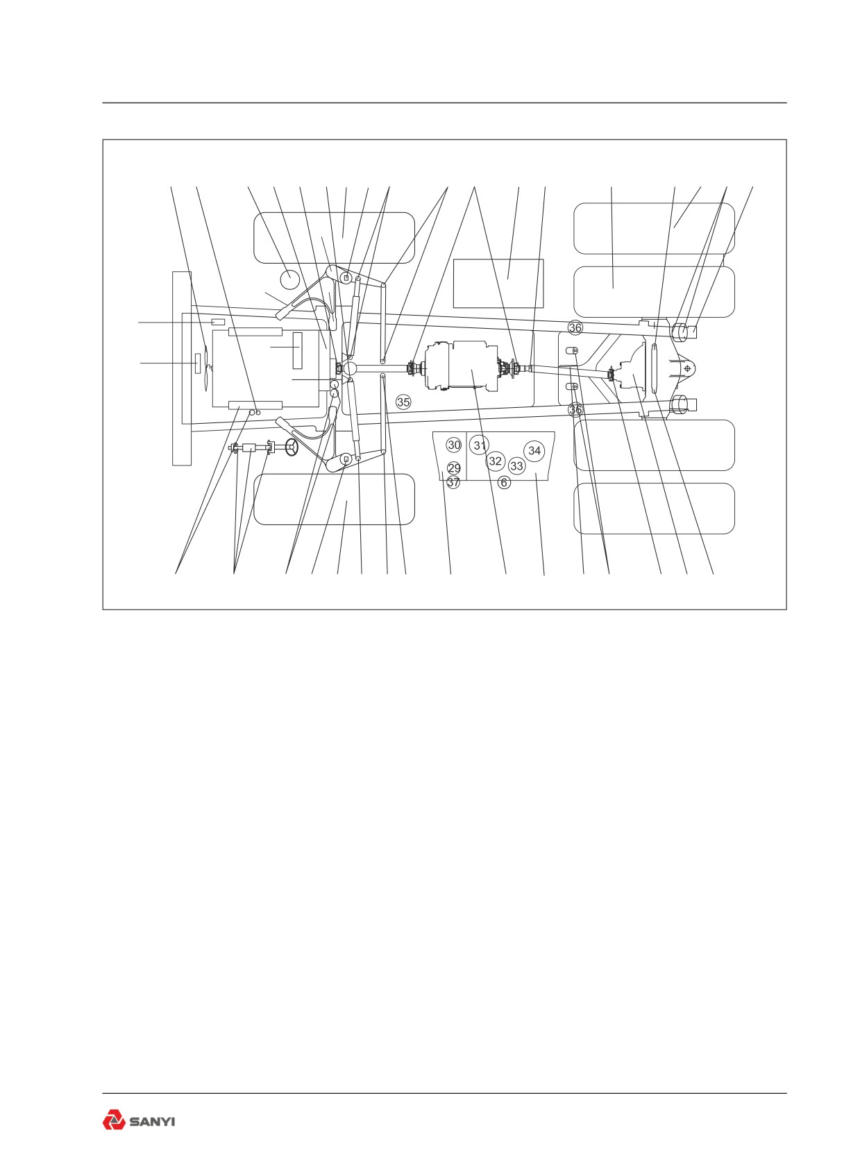
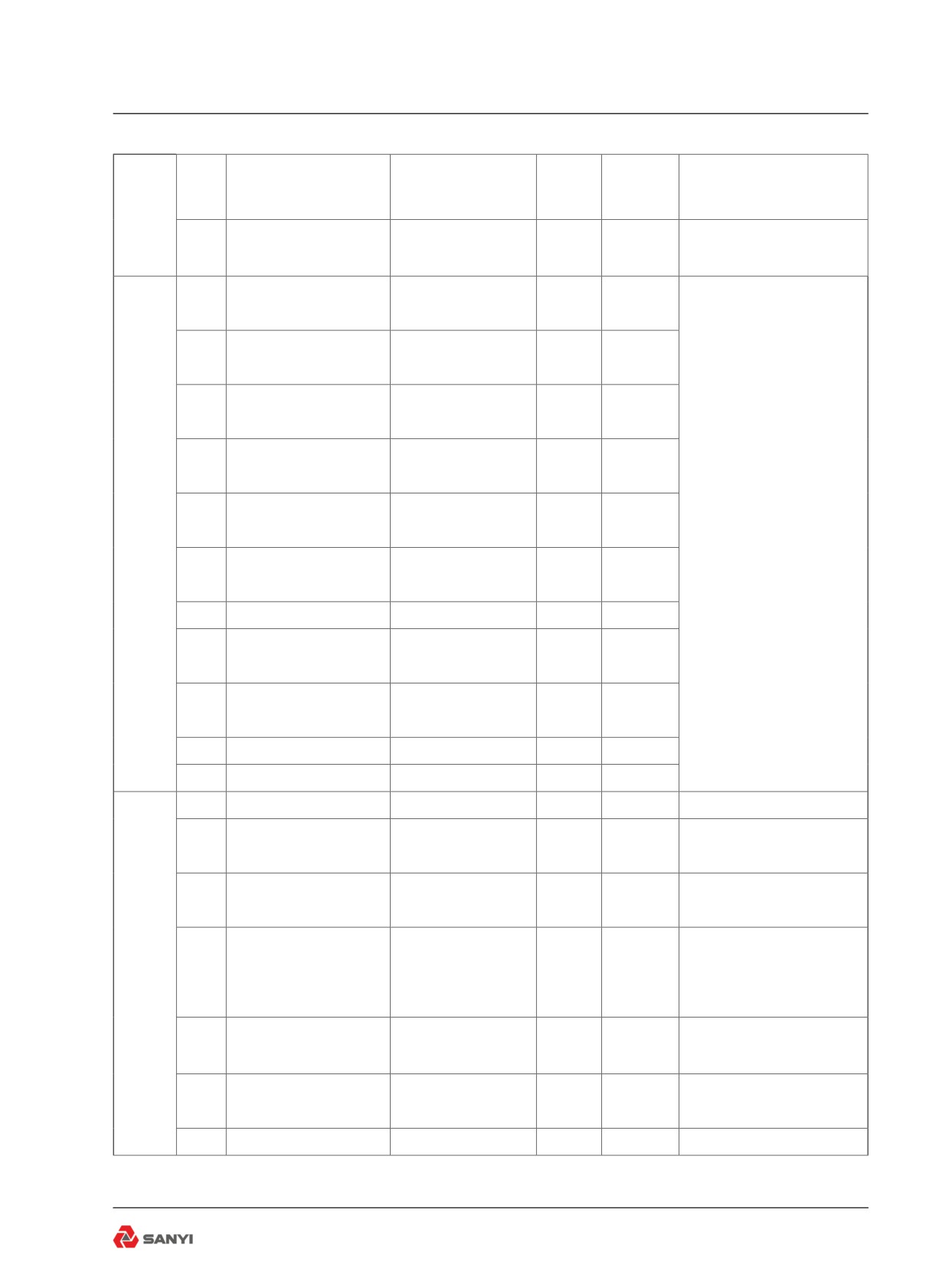
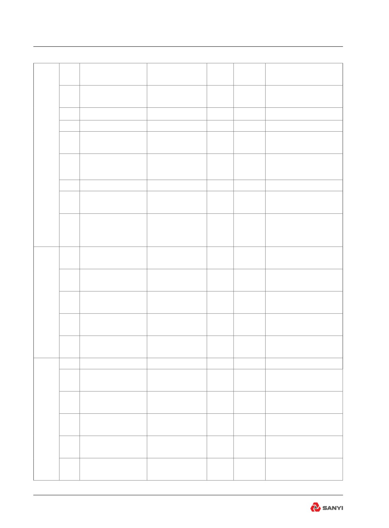
Small circles on the following illustration
represent points at which lubrication and/
or servicing must take place, at the intervals
indicated on the left hand side of the
lubrication and service chart. The numbered
circles on the illustration contain reference
numbers which correspond to the reference
numbers in the 'Ref. Points' column of the
lubrication and service chart.
Note: At each scheduled maintenance interval,
perform all previous checks in addition to the
ones specified.
8.3 Other Maintenance
As required
Seat belt - Inspect seat belts and replace if
damaged.
Note: Replace seat belt at least once 3 years
regardless of external appearance.
Wipers and cleaners -Inspect wiper blades
and replace if damaged. Top up washer
reservoir.
After first 10 hours of operation re-torque nuts
to1000-1300 N.m (739-961 pound-foot). Check
torque every 50 hours (weekly) thereafter.
Every 10 hours of operation
Walk around for inspection - Inspect the truck
according to instructions in Chapter 4 of the
Operation Manual.
Engine - Visually check engine for damage,
loose or frayed belts and listen for any unusual
8-8
Lubrication and Servicing
noises.
Engine Air Cleaners - Check air cleaner
piping, hoses and clamps. Change or clean
air cleaner element only when the color of
mechanical air resistance indicator turns
blue to red. Service vacuator valve daily.
Inspect and remove any obstructions from the
vacuator valve lips. Valve lips should be open
and pliable with engine stopped.
Note: Service air cleaners more often under
extremely dusty operating conditions.Radiator
Header Tank - Check coolant level and add if
low. Fill radiator header tank with coolant until
coolant reaches the bottom of the filler neck
and holds at that level.
Note: Any time a significant amount of coolant
is added, the DCA4 concentration MUST be
checked. If the concentration is low, engine
damage will result. Conversely, over-inhibiting
antifreeze solutions can cause silicate dropout.
Steering, braking and lifting systems-
Check for correct operation of all systems
beforeoperating the truck.
Steering hydraulic tank filter - Check steering
filter restriction warning indicator with the truck
empty,brakes released, oil at normal operating
temperature, engine operating at 1 500 r/min
and while turning the steering wheel at one
turn/sec. If the warning indicator illuminates,
the filter element should be replaced.
Replace the filter element,If the warning
indicator illuminates.
Fuel pre-filter - Discharge water and impurities.
Refer to Chapter 14 'Installation of Fuel Tank
and Pipeline',in the Maintenance Manual.
After first 150 hours of operating new or
rebuilt components.
Transmission - Drain oil, replace filters and
refill.
Differential - Drain oil and refill.
Planetaries - Drain oil and refill
8-9
Lubrication and Servicing
Every 250 hours of operation
Coolant Additive - Check and replenish DCA4
concentration as described.Coolant Filter(s) -
Replace coolant filter(s) if required. When
testing the DCA4 concentration, depending
on the level of DCA4, the coolant filter(s) may
not necessarily have to be changed.Refer
to Chapter 15 'Remote Water Tank',in the
Maintenance Manual.
Cooling Fan - Visually check the fan for
cracks, loose rivets, and bent or loose blades.
Check fan mounting and tighten if required.
Replace any fan that is damaged.
Note: The fan belt is maintained to the correct
belt tension by a spring loaded idler arm,
therefore, there is no need to check or adjust
belt tension.
Drive Belts - Visually check the belts and
replace if they are cracked or frayed. Adjust
belts that have a glazed or shiny surface which
indicates belt slippage. Correctly installed and
tensioned belts will show even pulley and belt
wear.Refer to Chapter 6 'Installation of Engine'
in the Maintenance Manual for drive belt
tension and adjustment of new and used drive
belts.
Front Brakes -Check pads and discs for wear
and replace where necessary.
Note: This service interval applies to normal
driving Check more frequently under more
severe conditions. Thickness of pad friction
material should never be allowed to wear
below 3 mm (0.12 in).
Oil Can Points - Oil hinges, and other working
parts with engine oil.
Fuel pre-filter - Replace filter element of fuel
pre-filter. Refer to Chapter 14 'Installation of
Fuel Tank and Pipeline',in the Maintenance
Manual.
Every 1000 hours of operation
Hydraulic System Pressure Checks - Check all
steering, body and braking system pressures.
Note: Instructions for checking pressure, and
8-10
Lubrication and Servicing
locations of pressure check points, are
contained in the relevant service manual
section. If the pressures are outwith the
specified settings then components in the
relevant system should be inspected, repaired
or replaced to ensure the correct operation
of the system. All safety instructions in the
relevant sections should be strictly adhered to.
Steering oil return filter-
Clean the housing for the filter , follow the
failure code from the display or working time
to replace filter if time over 1000hours.
Hoisting oil return filter - Clean the filter shell,
and install a new filter element.
Cooling oil return filter - Clean the housing for
the filter and replace new filter for it.
Steering In-line Filter - Clean the housing
for the filter , follow the failure code from the
display or working time to replace filter if time
over 500 hours.
Cooling pipeline filter - Replace with a new
spin-on filter element.
Every 2000 hours of operation
Steering In-line Filter - Clean filter housing and
install new element when indicated, or after 1
000 hours of operation,whichever comes first.
Steering in-line filter - Clean filter housing and
install new element.
Hoisting in-line filter - Clean filter housing and
install new element.
Cooling in-line filter - Clean filter housing and
install new element.
Engine and transmission
All information contained in the 'Lubrication
and Service Chart' was extracted from the
relevant manufacturers 'Operation and
Maintenance Manual',and was correct at
time of publication.User should ensure that
information contained in this chart reflects
the information shown in the relevant
manufacturers 'Operation and Maintenance
Manual' supplied with the Truck.
8-11
Lubrication and Servicing
8.4 Service Capacity
Ref.
Service Capacities
Identification
Lubricant
Points
Iiters
US gal
1
Engine Crankcase and Filters
EO
55
14.6
2
Transmission and Filters
HTF
85
22.5
3
Hoisting cooling tank
HO
158
41.8
4
Hoisting system and brake cooling system(Total)
HO
237
62.7
5
Steering Hydraulic Tank
HO
63
16.7
6
Steering and Braking Hydraulic System
HO
71
18.8
7
Cooling System
Coolant
130
34.4
8
Fuel Tank
Disel
470
124.2
9
Front Ride Cylinder(each)
HO
19
5.0
10
Rear Ride Cylinder(each)
HO
16
4.2
11
Engine Power Takeoff
EPL
4
1.1
12
Main reducer and differential assembly
EPL
52
13.3
13
Wheel Planetaries (Total)
EPL
43
11.9
14
Air Conditioning Compressor
PAG Oil
0.125
0.033
8-12