SANY SRT45 Off-Highway Truck. Safety,Operation and Maintenance Manual (2014) - page 1
Safety,Operation and Maintenance Manual
WARNING
Read and follow the safety precautions and instructions in this manual and on the mac-
hine decals. Failure to do can cause serious injury, death or property damage. Keep this
manual with the machine for reading and future reference.
Exemption Clauses
SPECIFIC DECLARATION
Mining truck is a critical earth/rock moving machine with high traffic ability,which is mainly
distributed to coal, iron ore, limestone, quarry,hydropower...
Sany assumes no responsibility for consequences caused by the following factors:
● Misuse of the truck due to failure to observe the information provided hereunder in this
manual;
● Unauthorized restructuring or modification to the truck;
● Use of non-genuine parts, or untested or unapproved parts or tools.
● Machine failure or damage resulted from natural disasters (such as earthquake,
typhoon,etc.), wars and other force majeure.
● Sany cannot anticipate all potential hazards that may occur on work site. Therefore, dump
truck operator and owner shall attach great importance to the issue of safety.
● Local government may impose higher standards for use of a dump truck. If local regulations
have conflicts to the safety rules described herein, whichever the stricter applies.
Obligations of Sany
● Offer quality truck along with correct information.
● Abide by after-sales service commitment and keep a record for all maintenance work and
repair work.
● Provide training for truck operators and service persons as required.
Obligations of owners or authorized persons
● Only trained personnel who fully understand the Parts Book and the Safety, Operation and
Maintenance Manual are allowed to operate and service the dump truck.
● Make sure that the truck operator and service person are qualified for this job and know their
responsibilities.
● Regularly inspect the safety awareness of related persons at work.
● Should any fault threatening safety occurs, shut down the truck immediately.
● Sany service personnel have the right to carry out safety inspection to the truck when
required.
● Besides the checks specified by Sany, local laws and regulations on truck shall also be
observed.
● Ensure timely maintenance and repair of the dump truck.
● Make a detailed plan for proper use of the dump truck.
SRT45Off-Highway Truck
Obligations of all operating personnel
● Any abnormalities that could bring improper operation of the dump truck or potential hazards
should be reported to your supervisor. The abnormalities should be corrected timely if
possible.
● All workers around the dump truck must know and obey all warning signals, and be alert to
safety of oneself and others.
● All operators must know the operating items and procedures.
● Be alert to any hazardous situation and immediately inform operator and signalman of the
hazards such as high voltage cables, irrelevant people and worse ground condition.
Obligations of manager
● The operator must have been trained and fully understand the provision of the Safety,
Operation
● and Maintenance Manual. The operator must be healthy and licensed. Otherwise he/she is
not allowed to operate the dump truck.
● Make sure that the operator has good sense, cooperation awareness and psychological
quality, or he/she is not allowed to operate or service the dump truck.
● Make sure that the signal person has good visibility and hearing ability, knows standard
command signals and can give signals clearly and correctly. The signal person shall also
have enough experience to recognize hazardous factors and timely tell the operator to avoid
the hazards.
● Make sure that the assistant person can positively identify the model and working condition
of dump truck and choose a suitable dump truck.
● Each operating personnel of a project shall bear certain safety responsibilities and is required
to timely report unsafe factors to the supervisor.
Table of Contents
Table of Contents
1 Foreword
1.1 Overview
1-1
1.2 Safety Information
1-3
1.3 Page Numbers
1-5
1.4 Regulation of Use
1-5
1.4.1 Machine applications
1-5
1.4.2 Directions of machine
1-5
1.5 Breaking in a New Machine
1-6
1.6 Visibility from Operator's Seat
1-7
1.7 Machine Information
1-9
1.7.1 Product identification plate
1-9
1.7.2 Engine identification plate
1-10
1.7.3 Display screen
1-11
1.7.4Table for serial number and distributor information
1-11
2 Safety
2.1 Safety Labels
2-5
2.1.1 Position for attaching safety labels
2-5
2.1.2 Safety labels
2-6
2.2 General Precautions
2-12
2.2.1 Safety rules
2-12
2.2.2 Abnormalities
2-12
2.2.3 Personal protective equipment
2-12
2.2.4 Fire extinguisher and first aid kit
2-13
2.2.5 Safety equipment
2-14
2.2.6 Cleaning your machine
2-14
2.2.7 Keeping the cab clean
2-15
2.2.8 Precautions when leaving the machine
2-15
2.2.9 Handholds and steps
2-16
2.2.10 Preventing burns
2-17
2.2.10.1 Hot coolant
2-17
2.2.10.2 Hot oil
2-17
I
Table of Contents
2.2.11 Preventing fire and explosion
2-18
2.2.11.1 Fire caused by fuel or oils
2-18
2.2.11.2 Fire caused by flammable materials
2-19
2.2.11.3 Fire caused by electric lines
2-19
2.2.11.4 Fire caused by hydraulic lines
2-19
2.2.11.5 Fire caused by illumination equipment
2-20
2.2.12 In the event of fire
2-20
2.2.13 Windshield cleaning detergent
2-20
2.2.14 Precautions when using ROPS(Roll over protective structure)
2-21
2.2.15 Attachment installation
2-21
2.2.16 Cab windows glasses
2-22
2.2.17 Unauthorized modification
2-22
2.2.18 Examination and confirmation of worksite
2-22
2.2.19 Operation on soft ground
2-23
2.2.20 Overhead power cables
2-24
2.2.21 Alternate exit
2-25
2.2.22 Ensure good visibilty
2-25
2.2.23 Asbestos hazard
2-26
2.3 Safe Operation Precautions
2-27
2.3.1 Safe starting
2-27
2.3.1.1 Safe mounting
2-27
2.3.1.2 Seat adjustment
2-27
2.3.1.3 Seat belt
2-28
2.3.1.4 Before starting the engine
2-28
2.3.1.5 Engine starting rules
2-29
2.3.1.6 Starting engine in cold season
2-29
2.3.1.7 Engine starting aid
2-30
2.3.1.8 After starting the engine
2-31
2.3.2 Operation
2-31
2.3.2.1 Inspection before operation
2-31
2.3.2.2 Prior-operation precautions
2-31
2.3.2.3 Precautions when traveling
2-32
2.3.2.4 Precautions when traveling on slopes
2-34
2.3.2.5 Precautions when operating
2-34
2.3.2.6 Precautions for accumulated snow, and ice
2-34
2.3.2.7 Parking the machine
2-35
2.3.2.8 Preparing the machine
2-36
II
Table of Contents
2.3.3 Transportation
2-37
2.3.3.1 Loading and unloading the machine
2-37
2.3.3.2 Transporting the machine
2-38
2.3.4 Battery
2-39
2.3.5 Towing
2-41
2.4 Precautions for Maintenance
2-42
2.4.1 Lock-out and tag-out
2-42
2.4.2 Select a working area
2-42
2.4.3 Prior-maintenance precautions
2-42
2.4.4 Preparing yourself
2-43
2.4.5 Stop engine before carrying out maintenance
2-44
2.4.6 Maintenance with engine running
2-45
2.4.7 Using proper tools
2-46
2.4.8 Handling suspension cylinder
2-46
2.4.9 Working under the machine
2-46
2.4.10 Work in loud noise
2-47
2.4.11 Use compressed air
2-47
2.4.12 Use a hammer
2-47
2.4.13 Welding operation
2-47
2.4.14 Precautions with high-pressure oil
2-48
2.4.15 High-pressure hoses
2-49
2.4.16 Hot cooling system
2-49
2.4.17 Air-conditioning system
2-50
2.4.18 High voltage precautions
2-50
2.4.19 Accumulator
2-51
2.4.20 Avoiding fire and explosion
2-51
2.4.21 Regular replacement of safetyrelated parts
2-52
2.4.22 Maintenance operation
2-52
2.4.23 Proper disposal of wastes
2-53
2.5 Precautions With Tires
2-54
2.5.1 Handling tires
2-54
2.5.2 Precautions when storing tire
2-55
3 CONTROLS AND OPERATING
3-1
3.1 Controls and Instruments
3-1
3.2 Indicator
3-2
III
Table of Contents
3.3 Instruments
3-4
3.4 Reversing monitor system
3-6
3.5 Switches
3-7
3.6 Combined switch
3-8
3.7 Air Conditioner Control Panel
3-9
3.8 Driver Seat
3-11
3.9 Seat Belt
3-11
3.10 Truck Controls
3-12
3.10.1 Braking
3-12
3.10.2 Service brake
3-12
3.10.3 Parking brake
3-13
3.10.4 Emergency brake
3-13
3.10.5 Retarder
3-13
3.11 Engine
3-15
3.11.1 Accelerator pedal
3-15
3.11.2 QUANTUM electronic fuel system
3-15
3.11.3 Quantum electronic fuel system - description
3-17
3.11.4 QUANTUM electronic fuel system - operation
3-18
3.11.5 Electronic fuel system diagnostic codes
3-20
3.12 Steering
3-24
3.13 Transmission
3-25
3.13.1 CEC2 Shift System
3-25
3.13.2 Introduction and operation
3-28
3.13.3 General Transmission Operation
3-32
3.13.4 Retrieving Diagnostic Codes
3-33
3.13.5 Clearing Diagnostic Codes
3-33
3.14 Body Control
3-38
3.15 The common fault code of vehicle monitor system
3-40
4 OPERATING THE TRUCK
4-1
4.1 Pre-Starting Inspection
4-1
4.2 Check of each component
4-3
4.3 Engine Operation
4-6
4.4 Start the Engine
4-8
4.5 Starting the Engine with Jumper Cables
4-10
4.6 Pre-Operating Checks
4-11
IV
Table of Contents
4.7 Braking Function Check
4-12
4.8 Service Brake Performance Check
4-12
4.9 Emergency Brake Performance Check
4-13
4.10 Driving and Stopping
4-13
4.11 Stopping the Engine
4-14
4.12 Parking
4-16
4.13 Prolonged Storage
4-16
5 WORKING THE TRUCK
5-1
5.1 Working the Truck
5-1
5.2 Loading
5-1
5.3 Hauling
5-3
5.4 Dumping
5-4
5.5 Empty Return
5-6
6 ROADING
6-1
6.1 General
6-1
6.2 Preparation Prior to Roading
6-1
6.3 In Case of Trouble
6-2
7 MOVING DISABLED TRUCK
7-1
7.1 Moving Disabled Truck
7-1
8 LUBRICATION AND SERVICING
8-1
8.1 Safety Precautions
8-1
8.2 Lubrication and Maintenance
8-2
8.3 Other Maintenance
8-8
8.4 Service Capacity
8-12
8.5 Recommended Lubricants
8-13
8.6 Maintenance Procedures
8-15
8.6.1 Daily (10hrs) maintenance inspection form
8-15
8.6.2 Maintenance inspection form for 150hrs
8-21
8.6.3 Maintenance inspection form for 250hrs
8-23
8.6.4 Maintenance inspection form for 300hrs
8-25
8.6.5 Maintenance inspection form for 450hrs
8-27
8.6.6 Maintenance inspection form for 500hrs
8-29
8.6.7 Maintenance inspection form for 600hrs
8-33
V
Table of Contents
8.6.8 Maintenance inspection form for 750hrs
8-35
8.6.9 Maintenance inspection form for 900hrs
8-37
8.6.10 Maintenance inspection form for 1000hrs
8-39
8.6.11 Maintenance inspection form for
1050hrs
8-43
8.6.12 Maintenance inspection form for
1200hrs
8-45
8.6.13 Maintenance inspection form for
1250hrs
8-47
8.6.14 Maintenance inspection form for
1350hrs
8-49
8.6.15 Maintenance inspection form for
1500hrs
8-51
8.6.16 Maintenance inspection form for
1650hrs
8-55
8.6.17 Maintenance inspection form for
1750hrs
8-57
8.6.18 Maintenance inspection form for
1800hrs
8-59
8.6.19 Maintenance inspection form for
1950hrs
8-61
8.6.20 Maintenance inspection form for
2000hrs
8-63
8.6.21 Maintenance inspection form for
2100hrs
8-67
8.6.22 Maintenance inspection form for
2250hrs
8-69
8.6.23 Maintenance inspection form for
2400hrs
8-71
8.6.24 Maintenance inspection form for
2500hrs
8-73
8.6.25 Maintenance inspection form for
2550hrs
8-77
8.6.26 Maintenance inspection form for
2700hrs
8-79
8.6.27 Maintenance inspection form for
2750hrs
8-81
8.6.28 Maintenance inspection form for
2850hrs
8-83
8.6.29 Maintenance inspection form for
3000hrs
8-85
8.6.30 Maintenance inspection form for
3150hrs
8-91
8.6.31 Maintenance inspection form for
3250hrs
8-93
8.6.32 Maintenance inspection form for
3300hrs
8-95
8.6.33 Maintenance inspection form for
3450hrs
8-97
8.6.34 Maintenance inspection form for
3550hrs
8-99
8.6.35 Maintenance inspection form for
3600hrs
8-101
8.6.36 Maintenance inspection form for
3750hrs
8-103
8.6.37 Maintenance inspection form for
3900hrs
8-107
8.6.38 Maintenance inspection form for
4000hrs
8-109
8.6.39 Maintenance inspection form for
4050hrs
8-115
8.6.40 Maintenance inspection form for
4200hrs
8-117
8.6.41 Maintenance inspection form for
6000hrs
8-119
8.6.42 Maintenance inspection form for
10000hrs
8-125
VI
Foreword
1 FOREWORD
1.1 Overview
The explanations, values, and illustrations
in this manual have been prepared based on
the latest information available as of the date
of its publication. Continuing improvements
in the design of this machine may lead to
additional changes that are not reflected in
this manual. Consult SANY or your SANY
distributor for the latest available information
concerning your machine or with questions
regarding information contained in this manual.
This manual gives details of the operation
and methods of inspection and maintenance
for this machine that must be obeyed in order
to use the machine safely. Most accidents are
caused by the failure to follow fundamental
safety rules for the operation and maintenance
of machines.
Read, understand and follow all
precautions and warnings in this manual and
on the machine before performing operation
and maintenance. Failure to do so may result
in serious injury or death.
SANY cannot predict every circumstance
that might involve a potential hazard when
the machine is used. Therefore, the safety
messages in this manual and on the
machine may not include all possible safety
precautions.
If you carry out any operation, inspection,
or maintenance under conditions that are not
described in this manual, understand that it
is your responsibility to take the necessary
precautions to ensure safety. In no event
should you or others engage in the prohibited
uses or actions described in this manual. If the
machine is operated mistakenly when carrying
out inspection and maintenance, there is
danger that it may lead to serious injury or
death.
1-1
Foreword
If you sell the machine, be sure to give
this manual to the new owner together with the
machine, so that all relevant personnel can
read it at any time.
If this manual is lost or damaged, contact
your distributor immediately to arrange for
its replacement. To ensure that the correct
manual is sent, check the serial number of the
machine and inform your SANY distributor.
The explanations, values, and illustrations
in this manual have been prepared based on
the latest information available as of the date
of its publication. Continuing improvements
in the design of this machine may lead to
additional changes that are not reflected in
this manual. Consult SANY Mining Equipment
Co.,Ltd. or your SANY distributor for the latest
available information concerning your machine
or with questions regarding information
contained in this manual.
The numbers in the illustrations
correspond to the numbers in ( ) in the text.
(For example: 1→⑴)
The letters in the illustrations correspond
to the letters in ○ in the text.
(For example: A→
)
SANY delivers machines that comply with
all applicable regulations and standards of
the country to which it has been shipped. If
this machine has been purchased in another
country, it may lack certain safety devices
and specifications that are necessary for
use in your country. If there is any question
about whether your product complies with the
applicable standards and regulations of your
country, consult SANY Mining Equipment Co.
or your SANY distributor before operating the
machine.
1-2
Foreword
1.2 Safety Information
Hazard alert words are used in this
manual and on some machine decals to inform
the operator of imminent or potential hazards
that lead to death, personal injury or property
damage.
1)Alert words
The sign is used for warning you the
potential danger of human injuries,
when it is used together with notes such
as “DANGER, WARING, CAUTION”, it
indicate the degree of hazard.
It indicates an imminently
DANGER
hazardous situation
which, if not avoided, will
result in death or serious
injury.
It indicates a potentially
WARNING
hazardous situation
which, if not avoided,
could result in death or
serious injury.
It indicates a potentially
CAUTION
hazardous situation
which, if not avoided,
may result in minor or
moderate injury. It can
also be used to alert
unsafe operation as which
may cause property loss.
1-3
Foreword
2)An example alert wording and alert text
WARNING
To prevent personal injury and
property damage, be sure lifting
equipment is of adequate capacity and
properly secured to do the job safely.
3)Other alert words
In addition to the safety-related alert
words above, the following words are used in
this manual to provide additional information
to which extra attention must be paid.
Note:
It is followed by information on how to avoid
reduction of machine service life.
Remark:
It is followed by very useful information.
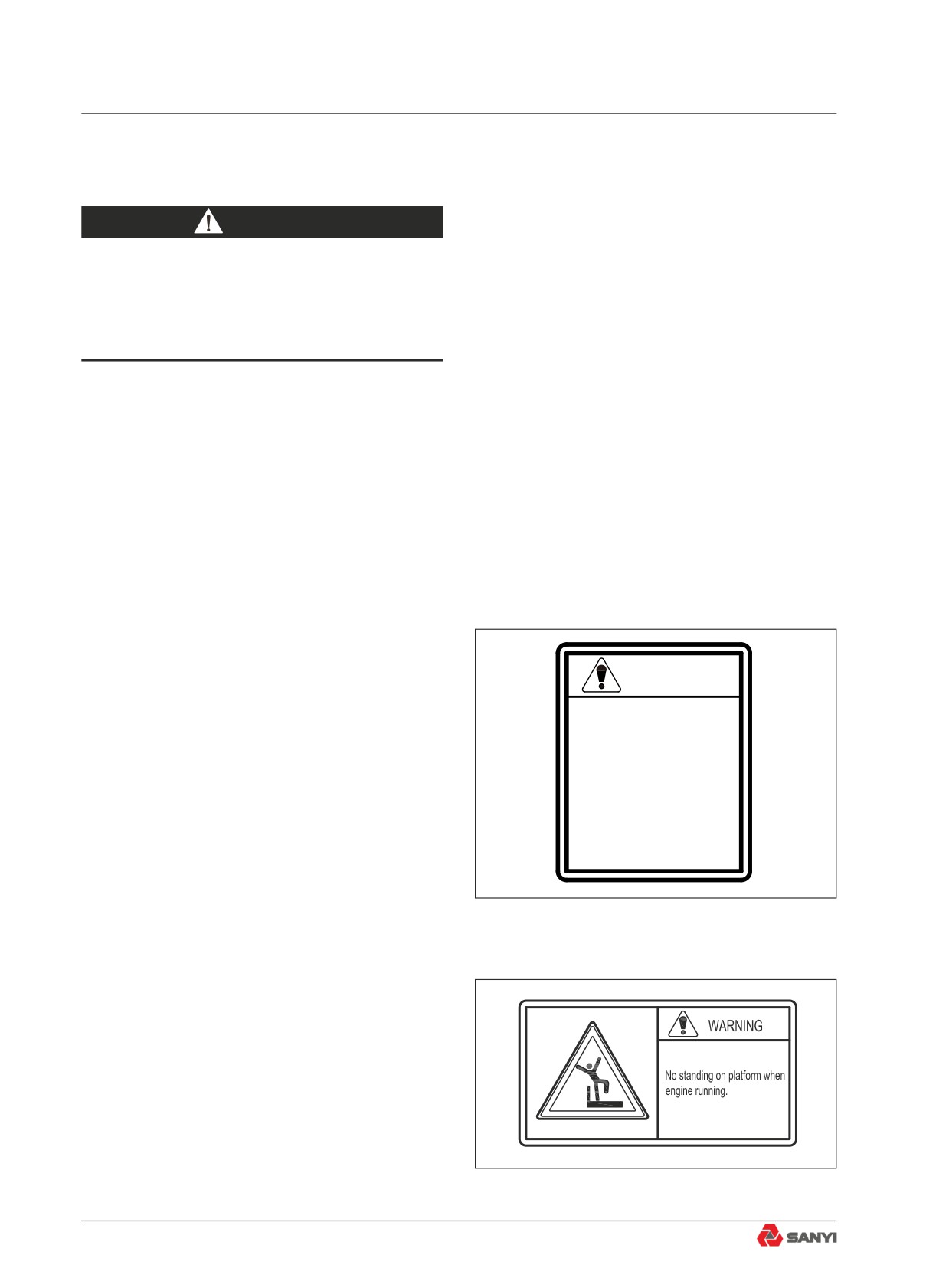
4)Safety decals
WARNING
Safety decals on the machine are used to
alert operator or maintenance personnel that
HIGH PRESSURE
potential hazards might be involved when the
Do not remove valves or fittings until pressure is
all released.
machine is being operated or serviced.
ACCUMULATOR
We use textual and graphical (or
Use Only Nitrogen Gas,Charging Pressure:
5.7 MPa,Ensure nitrogen precharge for
combined) decals to indicate a hazardous
proper operation of steering system.
situation and how to avoid such situation.
a.Textual safety decals
Fig. 1.2-1 is an example of textual safety
Fig. 1.2-1
decals.
b.Graphical safety decals
Graphical safety decals use images or
symbols to indicate a hazardous situation and
how to avoid it.
Fig. 1.2-2 is an example of graphical
safety decals.
Fig. 1.2-2
1-4
Foreword
1.3 Your Documentation Package
The documentation for this machine
includes the following items:
● Safety, Operation & Maintenance Manual
(SOMM) — This manual is in the operator
cab seat pocket.
● Parts Book — This publication consists
of parts lists and matching drawings for
ordering spare parts as-needed. If it was
not already shipped with your machine,
the parts book for your machine is
available directly from Sany.
1.3.1 Recommendations on using the
documentation
● This documentation applies only to this
machine and should not be used with any
other machines.
● To ensure that the documentation is
always complete and up to date:
● Keep all pages inside its binder (if shipped
loose leaf).
● Insert Sany replacement pages
mmediately into the appropriate book;
destroy old versions of those pages.
1.3.2 Documentation storage
● Always keep the operator manual and
load charts with the machine in the
operator cab.
● The parts book is best left either shelved
in the workshop area or office. It should
always be available to the maintenance
and service personnel as required.
1-5
Foreword
1.4 Page Numbers
The pages in this manual are numbered
as the following:
2-10
Page 10 of Chapter 2
Chapter 2
1.5 Regulation of Use
1.5.1 Machine applications
Sany Mining Trucks are designed to be
Front
Right
used mainly for the following work:
Traveling with a load
Left
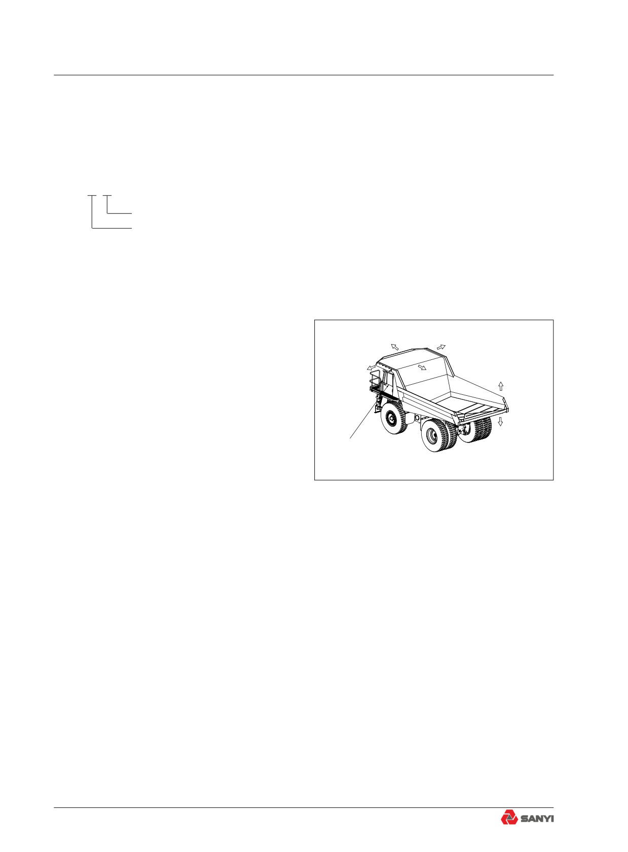
Rear
Top
1.5.2 Directions of machine
In this manual, the directions of the
Down
machine (front, rear, and left, right) are
determined according to the view from the
Operator 's seat
operator’s seat in the direction of travel (front)
of the machine.
Fig. 1.5-1
1.6 Breaking in a New Machine
Your machine has been thoroughly
adjusted and tested before shipment.
However, initial operation of the machine
under severe conditions can adversely affect
the performance of the machine or shorten the
machine life.
Therefore, Sany recommends that you
allow a break-in period of 100 operating hours
for a new machine.
During the break-in period:
● Let the machine preheat prior to any
operation.
● Avoid engaging gear or operating the
pedal.
● Avoid sudden starts or fast movements or
1-6
Foreword
stops.
● Always let the system cool down at the end of the working day.
1.7 Visibility from Operator's Seat
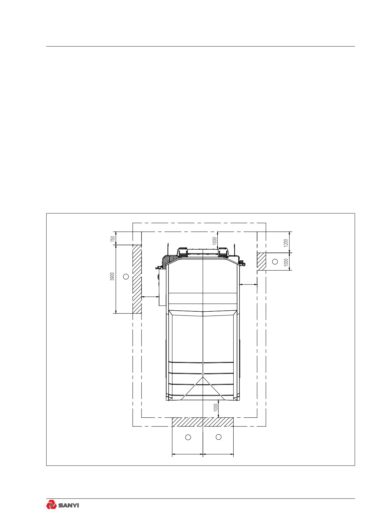
The visibility standards (ISO 5006) for this machine require a view shown in the diagram
below.
Visibility in immediate area
The visibility of this machine in the area 1 m from the outside surface of the machine at a
height of 1.5 m is shown in the diagram below. The hatched area (A) shows the area where the
view is blocked by part of the machine when mirrors or other aids to visibility are installed as
standard. Please be fully aware that there are places that cannot be seen when operating the
machine.
A
A
1000
1000
A
A
1743
1743
Fig. 1.7-1
1-7
Foreword
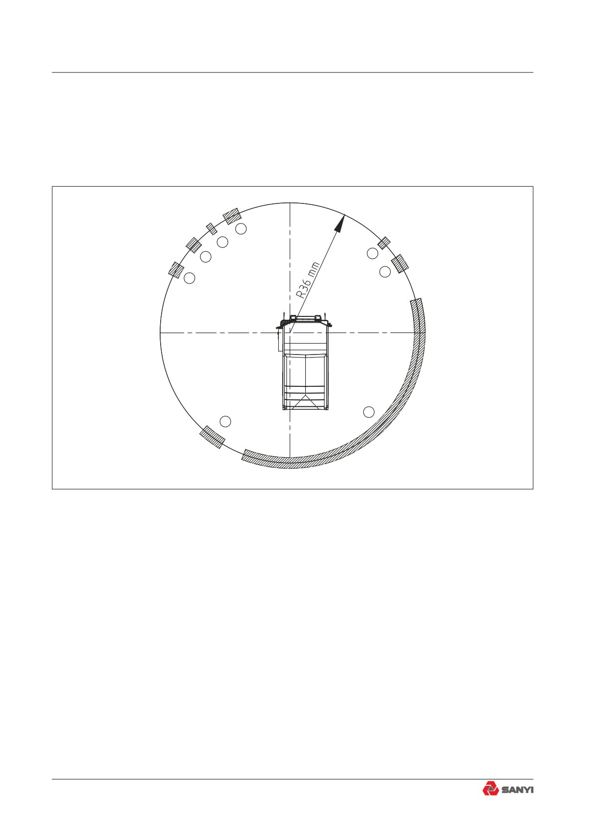
24-M radius visibility
The visibility at a radius of 24 m from the machine is as shown in the diagram below. The
hatched areas (B) show the areas where the view is blocked when mirrors or other aids to
visibility are installed as standard. Please be fully aware that there are places that cannot be seen
when operating the machine.
B
B
B
B
B
B
B
B
Fig. 1.7-2
1-8
Foreword
1.8 Machine Information
The serial numbers and model numbers
on the components are the only numbers that
your Sany distributor will need when ordering
replacement parts or requiring assistance for
your equipment. It is a good idea to record
this information in this manual for future use.
Below are the locations of the data plates.
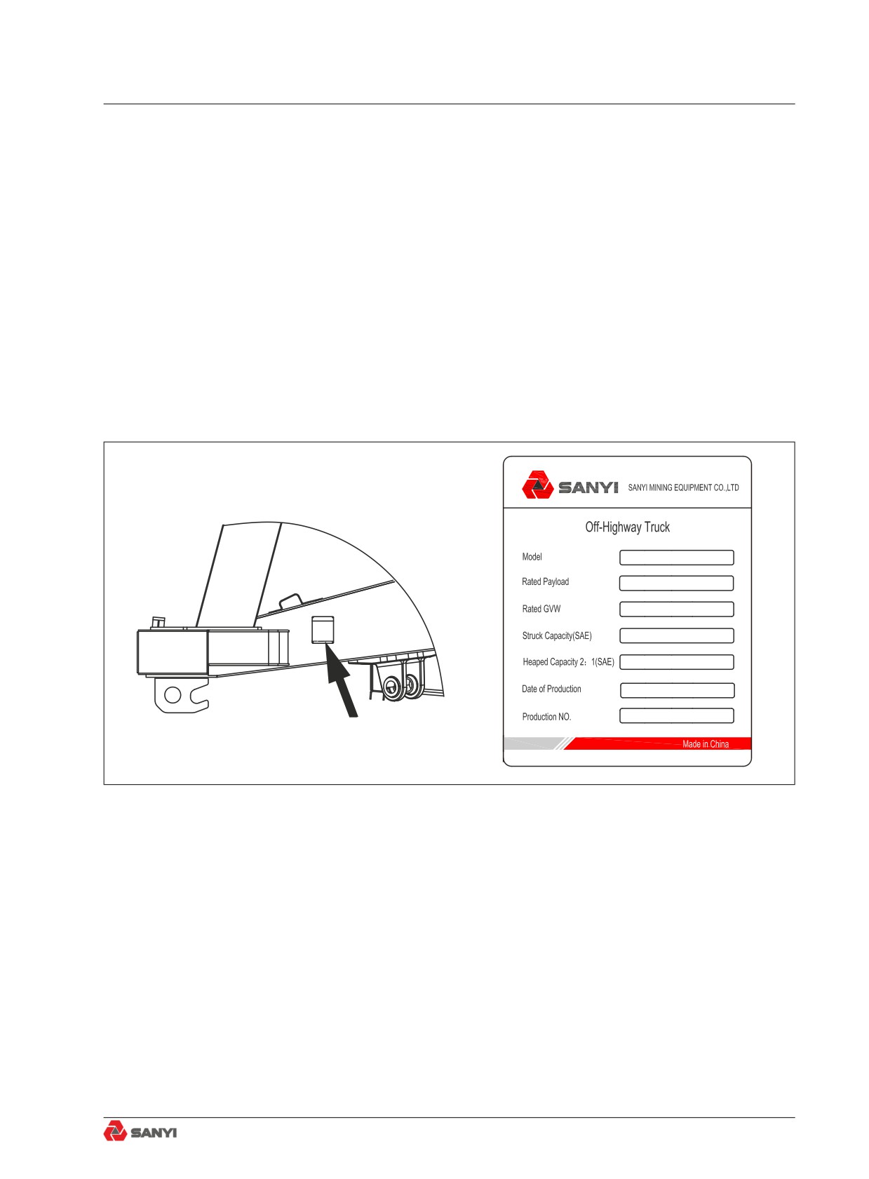
1.8.1 Product identification plate
It is located on the left front end of the
frame.
left front end of the frame
Fig. 1.8-1
1-9
Foreword
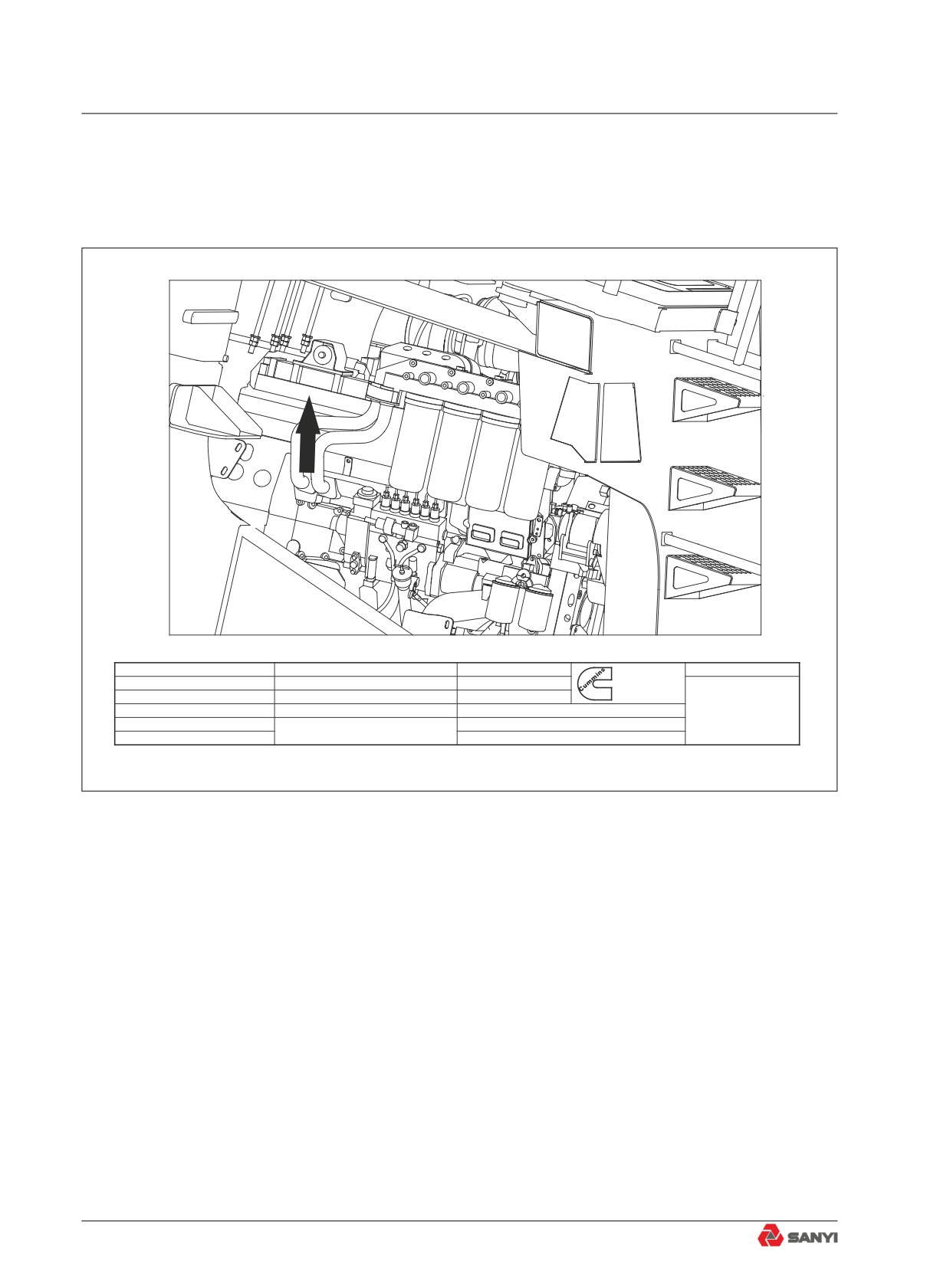
1.8.2 Engine identification plate
The engine identification plate is on the
right front of engine cylinder head.
Engie No.
37256546
Displacement
30.5/1860 L:in3
Valve Lash Cold
( mm/in)
Warrty Start Date
o
IMPORTANT ENGINE INFORMATION
Family D57
Static Injection Timing
0.5
BTDC
Intake
0.432/0.017
In the U.S. this engine is soley for
export and is therefore exempt under
Model QST30
Fuel Rate @ Advertised Power
270
mm3/stroke
Exhaust
0.813/0.032
40 CFR 1068.240 from U.S.
S.O. No. so10727
Advertised Power 783 /1050
kW:HP at
2100
RPM
emssions standards and
related requirements. Outside the U.S.
WARNING: Injury may result and warranty is volded
this engine may be subject to other
Ref. No.WZU2-SY-SRT95-Q30-1
Peak Torque
4629 /3414 Nm:ft-lb at
1300
RPM
emissions regulations.
if fuel rate, speed or altitude exceeds published
Engie No.37256546
maximum values for this modeland application.
Assembled by Cummins Engine Co.,Inc. U.S.A.
4295379
Fig. 1.8-2
1-10
Foreword
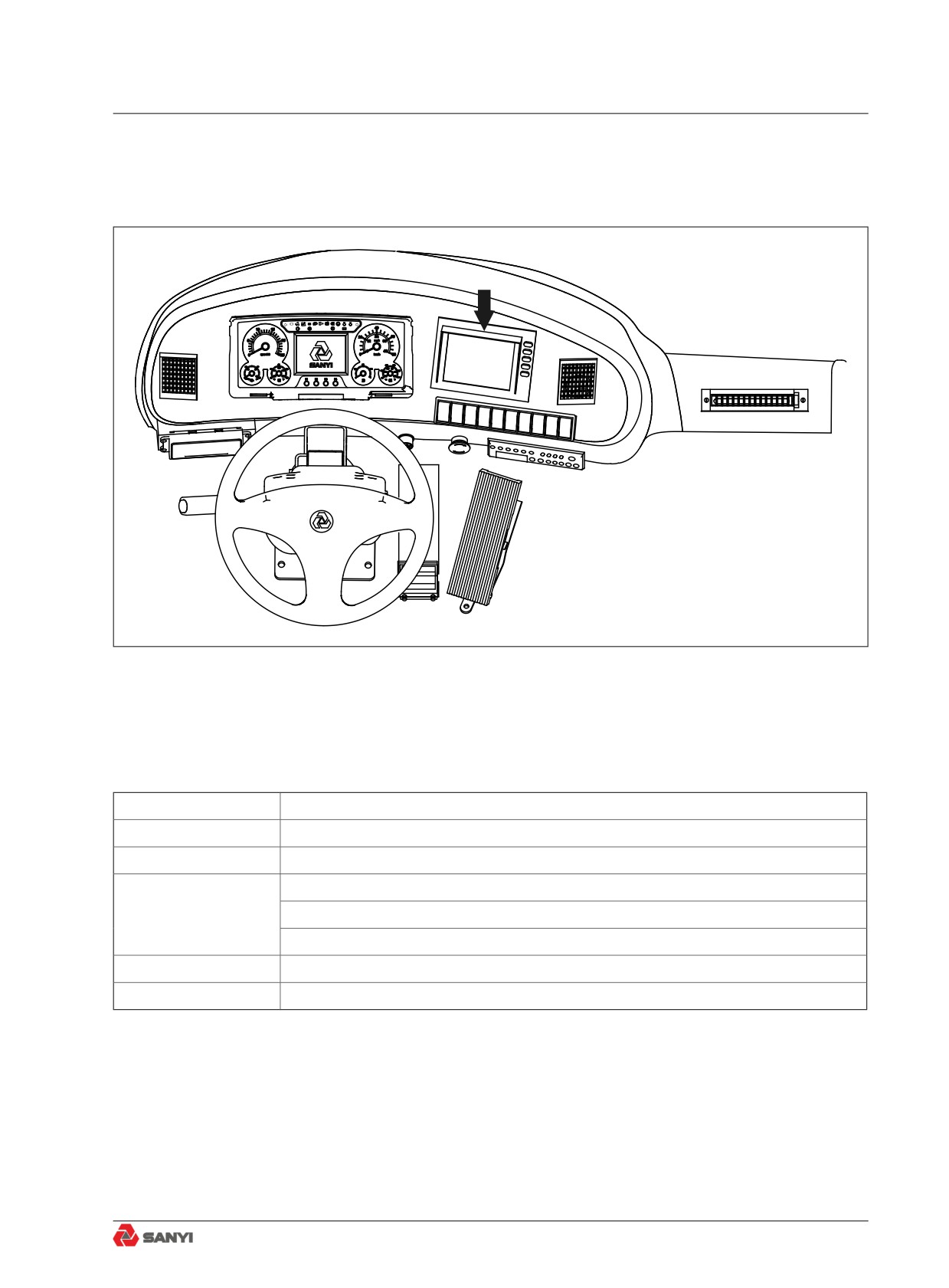
1.8.3 Display screen
The position of display screen is shown as
follows:
P
!
!
Fig. 1.8-3
1.8.4 Table for serial number and distributor information
Machine Serial No.
Engine Serial No.
Distributor Name:
Address:
Service Personnel
Phone/Fax
1-11
Foreword
1-12
Safety
Safety
2 Safety
2-5
2.1 Safety Labels
2-5
2.1.1 Position for attaching safety labels
2-5
2.1.2 Safety labels
2-6
2.2 General Precautions
2-12
2.2.1 Safety rules
2-12
2.2.2 Abnormalities
2-12
2.2.3 Personal protective equipment
2-12
2.2.4 Fire extinguisher and first aid kit
2-13
2.2.5 Safety equipment
2-14
2.2.6 Cleaning your machine
2-14
2.2.7 Keeping the cab clean
2-15
2.2.8 Precautions when leaving the machine
2-15
2.2.9 Handholds and steps
2-16
2.2.10 Preventing burns
2-17
2.2.10.1 Hot coolant
2-17
2.2.10.2 Hot oil
2-17
2.2.11 Preventing fire and explosion
2-18
2.2.11.1 Fire caused by fuel or oils
2-18
2.2.11.2 Fire caused by flammable materials
2-19
2.2.11.3 Fire caused by electric lines
2-19
2.2.11.4 Fire caused by hydraulic lines
2-19
2.2.11.5 Fire caused by illumination equipment
2-20
2-1
Safety
2.2.12 In the event of fire
2-20
2.2.13 Windshield cleaning detergent
2-20
2.2.14 Precautions when using ROPS(Roll over protective structure)
2-21
2.2.15 Attachment installation
2-21
2.2.16 Cab windows glasses
2-22
2.2.17 Unauthorized modification
2-22
2.2.18 Examination and confirmation of worksite
2-22
2.2.19 Operation on soft ground
2-23
2.2.20 Overhead power cables
2-24
2.2.21 Alternate exit
2-25
2.2.22 Ensure good visibilty
2-25
2.2.23 Asbestos hazard
2-26
2.3 Safe Operation Precautions
2-27
2.3.1 Safe starting
2-27
2.3.1.1 Safe mounting
2-27
2.3.1.2 Seat adjustment
2-27
2.3.1.3 Seat belt
2-28
2.3.1.4 Before starting the engine
2-28
2.3.1.5 Engine starting rules
2-29
2.3.1.6 Starting engine in cold season
2-29
2.3.1.7 Engine starting aid
2-30
2.3.1.8 After starting the engine
2-31
2.3.2 Operation
2-31
2.3.2.1 Inspection before operation
2-31
2.3.2.2 Prior-operation precautions
2-31
2.3.2.3 Precautions when traveling
2-32
2.3.2.4 Precautions when traveling on slopes
2-34
2.3.2.5 Precautions when operating
2-34
2.3.2.6 Precautions for accumulated snow, and ice
2-34
2.3.2.7 Parking the machine
2-35
2.3.2.8 Preparing the machine
2-36
2.3.3 Transportation
2-37
2.3.3.1 Loading and unloading the machine
2-37
2.3.3.2 Transporting the machine
2-38
2.3.4 Battery
2-39
2.3.5 Towing
2-41
2-2
Safety
2.4 Precautions for Maintenance
2-42
2.4.1 Lock-out and tag-out
2-42
2.4.2 Select a working area
2-42
2.4.3 Prior-maintenance precautions
2-42
2.4.4 Preparing yourself
2-43
2.4.5 Stop engine before carrying out maintenance
2-44
2.4.6 Maintenance with engine running
2-45
2.4.7 Using proper tools
2-46
2.4.8 Handling suspension cylinder
2-46
2.4.9 Working under the machine
2-46
2.4.10 Work in loud noise
2-47
2.4.11 Use compressed air
2-47
2.4.12 Use a hammer
2-47
2.4.13 Welding operation
2-47
2.4.14 Precautions with high-pressure oil
2-48
2.4.15 High-pressure hoses
2-49
2.4.16 Hot cooling system
2-49
2.4.17 Air-conditioning system
2-50
2.4.18 High voltage precautions
2-50
2.4.19 Accumulator
2-51
2.4.20 Avoiding fire and explosion
2-51
2.4.21 Regular replacement of safetyrelated parts
2-52
2.4.22 Maintenance operation
2-52
2.4.23 Proper disposal of wastes
2-53
2.5 Precautions With Tires
2-54
2.5.1 Handling tires
2-54
2.5.2 Precautions when storing tire
2-55
2-3
Safety
2-4
Safety
2 SAFETY
2.1 Safety Labels
The following warning signs and safety are used on this machine.
● Be sure that you fully understand the correct position and content of labels.
● To ensure that the content of labels can be read properly, be sure the they are in the correct
place and always keep them clean. When cleaning them, do not use organic solvents or
gasoline. These may cause the labels to peel off.
● There are also other labels in addition to the warning signs and safety labels. Handle those
labels in the same way.
● If labels are damaged, lost, or cannot be read properly, replace them with new ones.
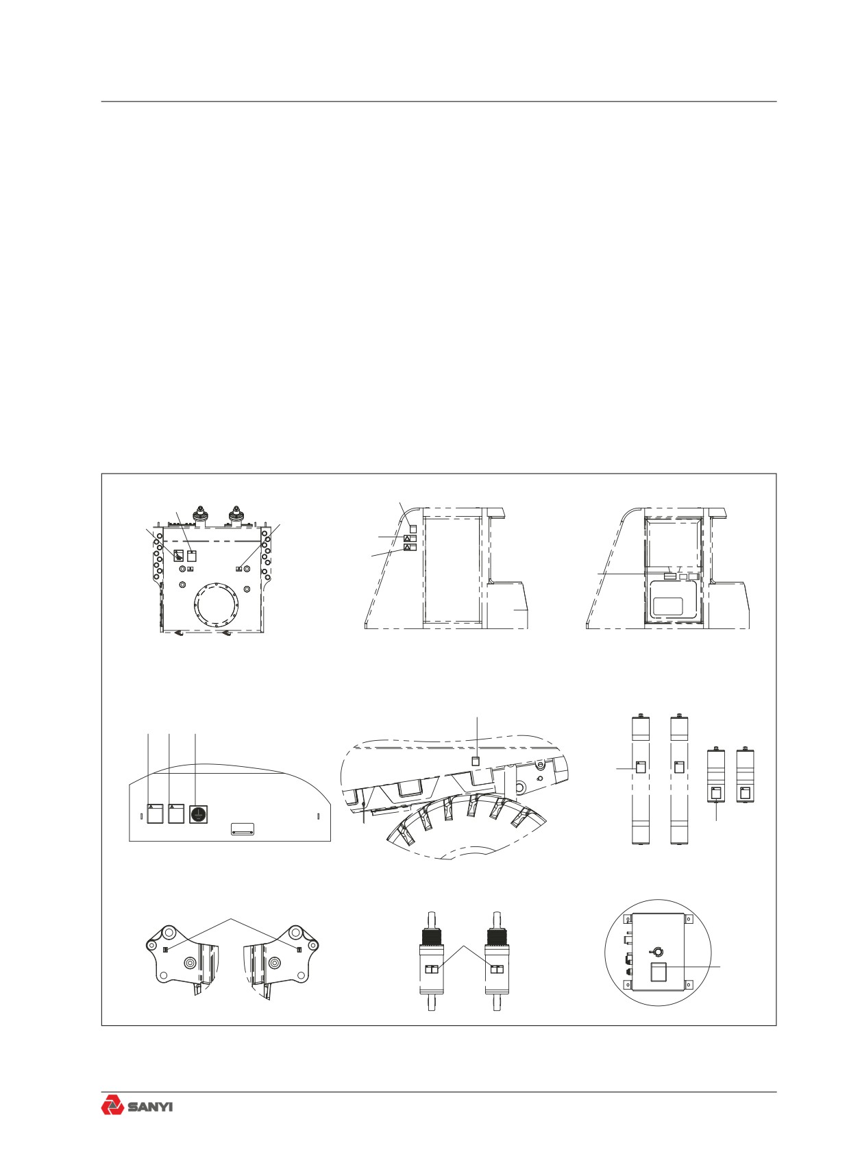
2.1.1 Position for attaching safety labels
2
3
4
2
5
6
7
Hydraulic oil tank
Cab(Right side outer shell)
Cab(Left side outer shell)
9
10
11
12
8
8
Battery box assembly
Accumulator
Frame rear part(left)
13
14
1
Rear tail seat
Fig. 2.1-1
2-5
Safety
2.1.2 Safety labels
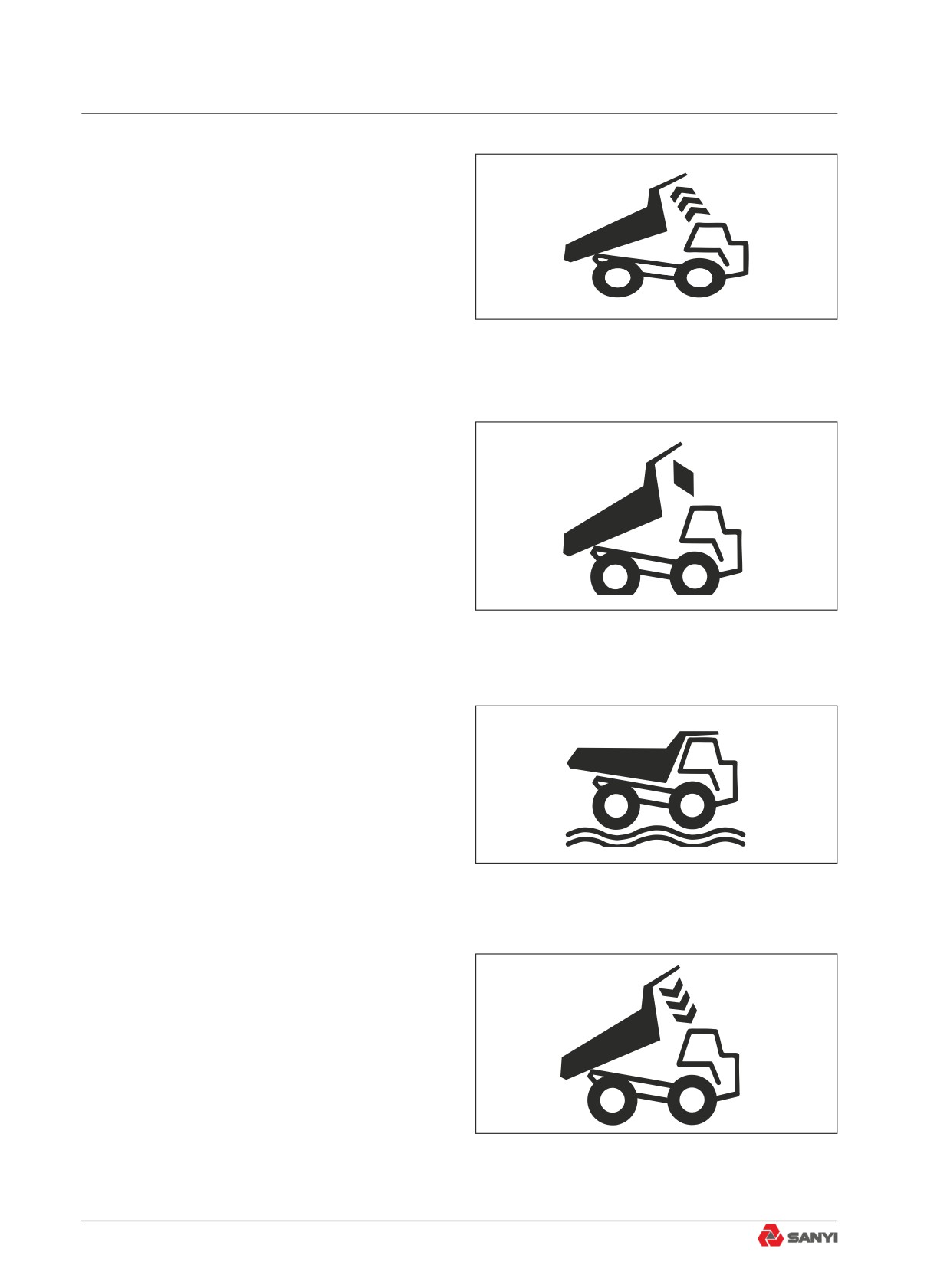
(1)Lifting control label
● This label is located at the left hand side
of the cab driver seat.
● This location of lifting handle means the
carriage dip angle increases and unload.
Fig. 2.1-2
● This location of lifting handle means the
carriage dip angle remain unchanged.
Fig. 2.1-3
● This location of lifting handle means the
carriage is in suspension state.
● The handle must be in this location when
the machine is stopped or moving.
Fig. 2.1-4
● This location of lifting handle means the
carriage dip angle decreases,and the
carriage will be downward to locate on the
frame.
Fig. 2.1-5
2-6
Safety
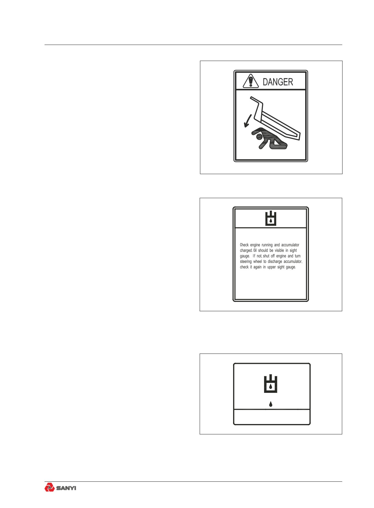
(2) Carriage warning labels
● This label are located at right cab gate of
cab, hydraulic oil tank and fuel tank. When
the carriage dip angle decrease until
located on the frame, neighboring people
should be careful to prevent be hurt.
Fig. 2.1-6
(3)Hydraulic oil instruction label
● This label is located on the hydraulic oil
tank.
● Check engine running and accumulator
charged. Oil should be visible in sight
gauge. If not, shut off engine and turn
steering wheel to discharge accumulator,
check it again in upper sight gauge.
Fig. 2.1-7
(4)Hydraulic oil position
● This label is located on the hydraulic oil
tank.
● It means the hydraulic oil position, oil
should be visible in sight gauge.
Fig. 2.1-8
2-7
Safety
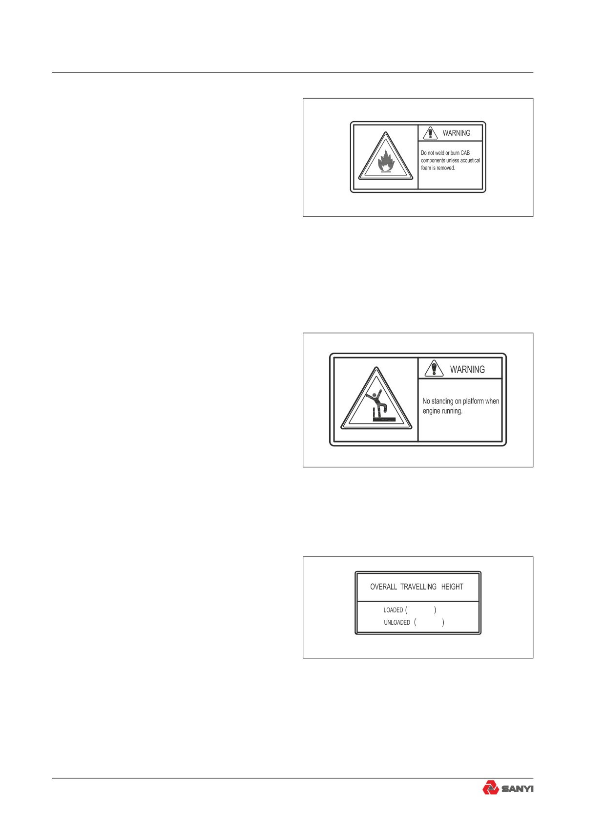
(5)Cab welding warning label
● This label is located at the right cab gate
side.
● Do not weld or burn CAB components
unless acoustical foam is removed.
Fig. 2.1-9
(6)No standing warning label
● This label is located at the right cab gate
side.
● The people is not allowed standing on the
platform when the engine running, and
should fall down and hold up handrail to
prevent tumbling.
Fig. 2.1-10
(7)Machine moving high warning label
● This label is located at the middle side of
right cab gate.
● The machine whole high is 4.92meters
unloaded and 4.89 meters full loaded.
192.52in
Be care when the machine pass through
193.70in
cave or bridge.
Fig. 2.1-11
2-8
Safety
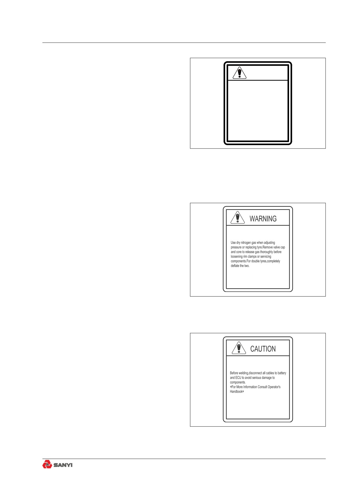
(8)Accumulator warning label
● This label is located on the barrel wall of
WARNING
accumulator.
● To prevent personal injury and equipment
HIGH PRESSURE
Do not remove valves or fittings until pressure is
damage, be sure pressure in the
all released.
accumulator is relieved completely before
ACCUMULATOR
Use Only Nitrogen Gas,Charging Pressure:
disassembling valves and connects.
5.7 MPa,Ensure nitrogen precharge for
proper operation of steering system.
Fig. 2.1-12
(9)Tyre warning label
● To prevent personal injury and equipment
damage, please read service manual
carefully before tyre aeration or
maintenance.
Fig. 2.1-13
(10)Battery cable warning label
● This label is located on the top battery
box.
● Weld will produce big electric current
which may damage electric elements , so
● just do according with warning label and
operator’s handbook.
Fig. 2.1-14
2-9
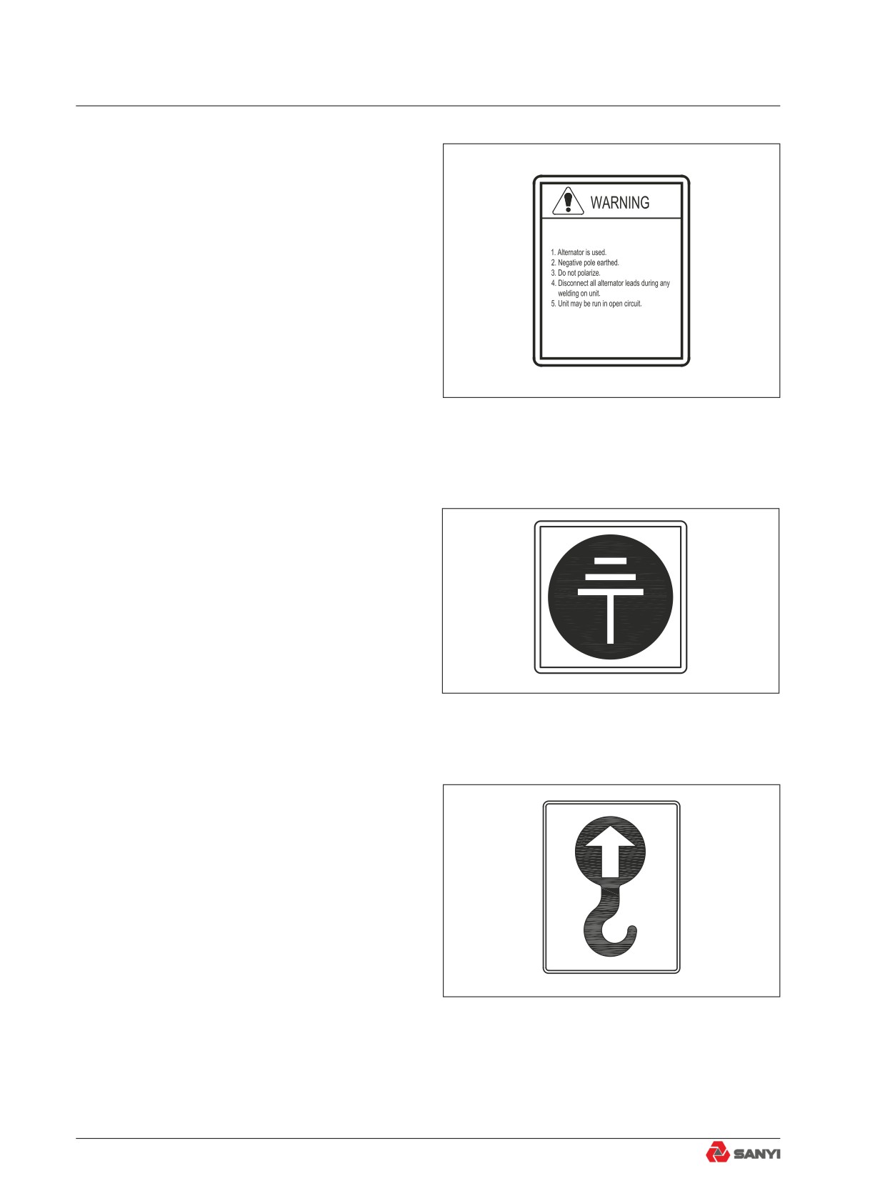
Safety
(11)Alternator warning label
● This label is located on the battery box.
Please do as the warning label and
handbook when operating machine.
Fig. 2.1-15
(12)Grounding label
● This label is located on the top battery
box.
● It means there is a negative electrode
grounding system in battery assembly.
Fig. 2.1-16
(13)Cliver label
● There are four cliver position, two borrow
joint hole between rear tail seat and
carriage, two located below bumper.
Fig. 2.1-17
2-10
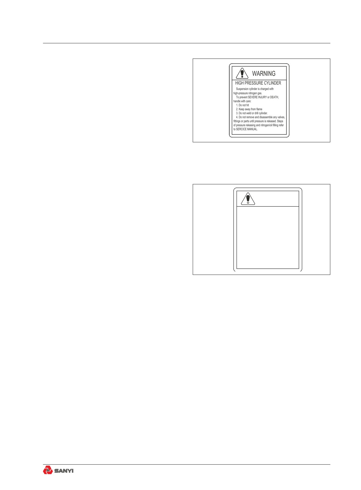
Safety
(14)Suspension warning label
● This label is located on the barrel wall of
suspension cylinder.
● To prevent personal injury and equipment
damage, please do as the warning label
and service manual when maintenance.
Fig. 2.1-18
(15) Open water cap warning label
● This label is located on the distance water
box.
●
To prevent personal injury ,never remove
WARNING
hot radiator cap.
Never remove hot rediator cap
Fig. 2.1-19
2-11
Safety
2.2 General Precautions
2.2.1 Safety rules
● Only trained personnel are allowed to
operate and service the machine.
● All safety rules, precautions and
instructions must be followed when
operating and servicing the machine.
● Taking alcohol or drug could seriously
impair one's ability in operating or
repairing the machine, and it is hazardous
for you and other persons.
● When working with another operator or
job site traffic signalman, be sure to make
all people understand all hand signals to
be used.
2.2.2 Abnormalities
In case of any abnormalities found during
operation and maintenance, such as noise,
vibration,odor, incorrect gauge display,
smoke,or oil leakage, contact your Sany
distributor and take necessary measures.
Never operate the machine before the faults
are corrected.
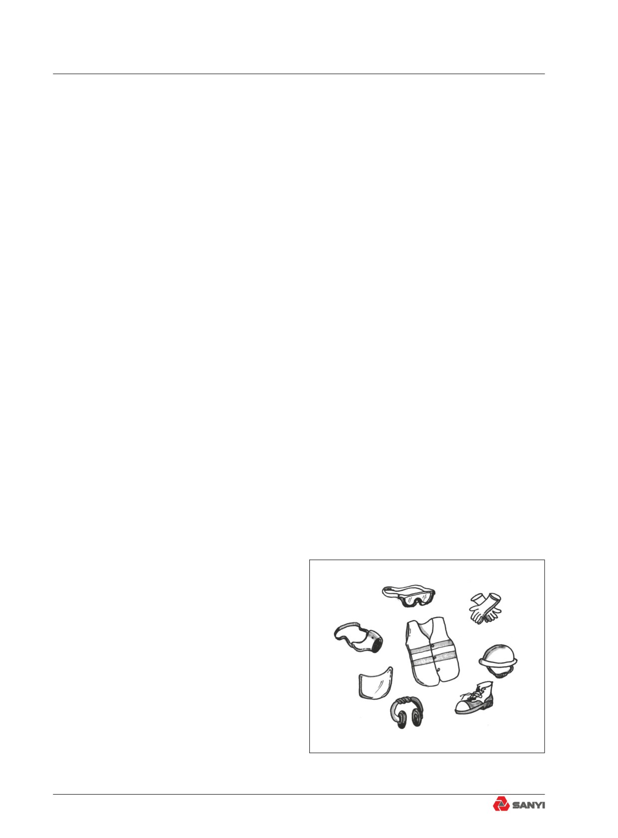
2.2.3 Personal protective equipment
Wear proper work clothes and personal
protective equipment (PPE) suitable for the
environment of the job site. You may need:
● Hard hat
● Safety shoes
● Safety glasses, goggles or face shield
● Reflective protective clothing
● Hearing protection
● Dust mask
Wear all necessary PPEs as well as other
equipment required by your employer, local
Fig. 2.2-1
government, and local laws and regulations.
2-12
Safety
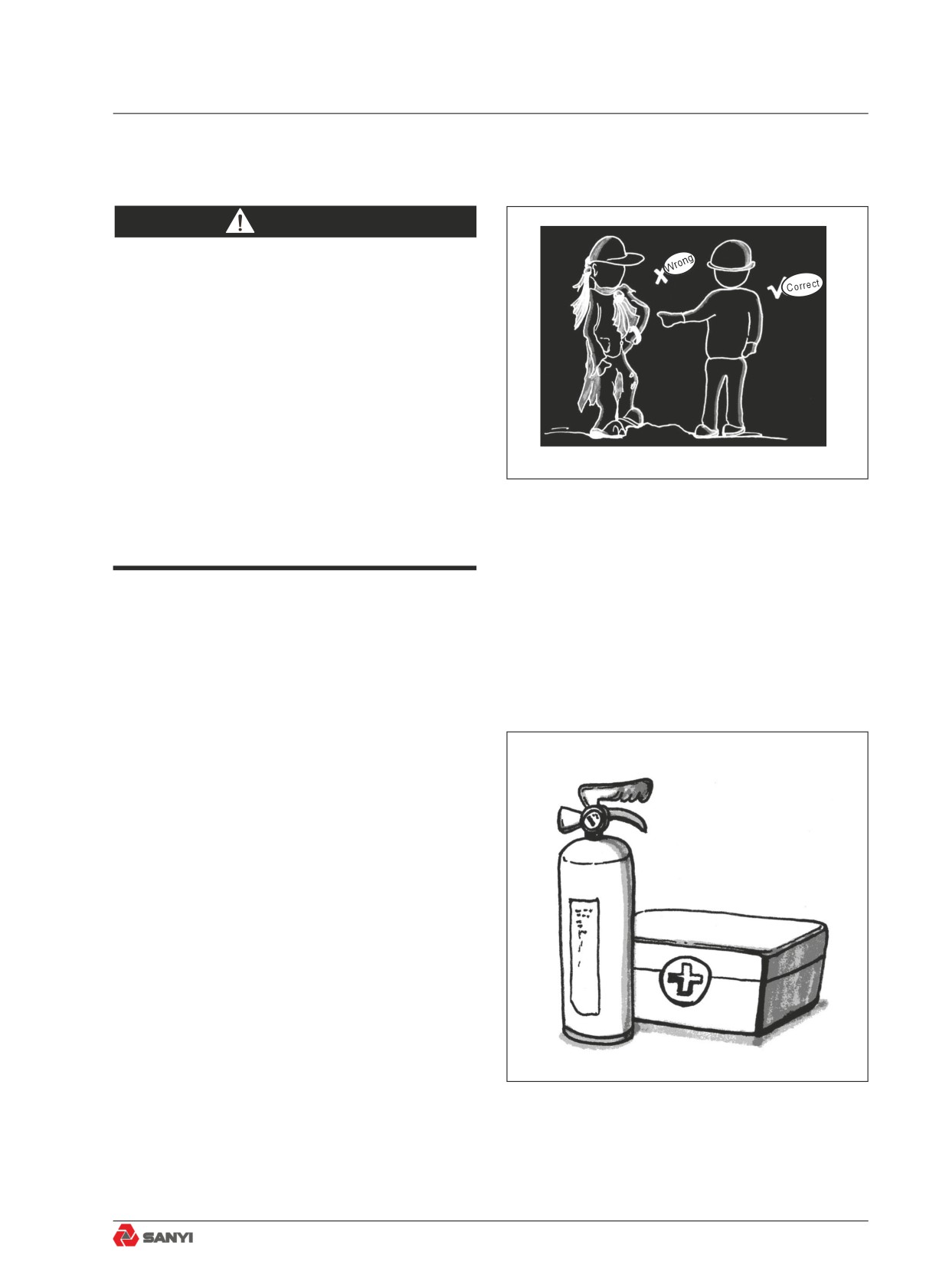
Never take a risk.
CAUTION
Never wear slack clothing and jewelry,which
may get caught by control evers
or other machine parts.
Long hair can be caught in moving parts. Tie
your hair if necessary to avoid such hazard.
Always have your hard hat and safety
shoes on. Wear safety goggles, face masks,
gloves, hearing protection and safety belt if
necessary.
Make sure all PPEs are in good condition
before use.
Fig. 2.2-2
Never listen to radio or music with ear plugs
on during operation.
2.2.4 Fire extinguisher and first aid kit
To prevent injury or fire, observe the following
precautions:
● First aid kit and fire extinguisher should be
available nearby.
● Read and understand the instruction
attached to fire extinguisher. Use fire
extinguisher properly.
● Regular inspection and maintenance shall
be done to ensure proper functioning of
fire extinguisher at any time.
● Check the first aid kit regularly and
replenish it when necessary.
● Make emergency scheme to deal with fire
and accidents.
Fig. 2.2-3
2-13
Safety
2.2.5 Safety equipment
To protect you and others around you, your
machine may be equipped with the following
safety equipment. Make sure that they are
secured in place and in good condition.
● Falling Object Protection (Body pivot pin)
● Rollover Protection
● Sealt belt
● Lamps
● Horn
● Guards
● Backup alarm
Fig. 2.2-4
● Mirrors
● Fire extinguisher
CAUTION
● Make sure all covers and caps are in
proper place. Repair or replace any of them
immediately once found damaged.
● Know how to use these facilities and use
them correctly.
● Never remove the guard rail of the operator
cab (unless necessary) .
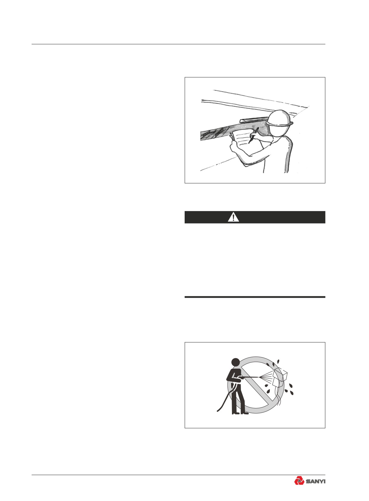
2.2.6 Cleaning your machine
● Clean the windshields, mirrors and lights.
Make sure that the operating area, steps
and handholds are free from oil, grass,
snow, ice or mud, which can cause you
to slip and fall. Remove the mud on your
soles before getting on the machine.
● If water has penetrated into the electrical
system, never rush to power on your
machine and start the engine, which
can cause machine failure or PC board
damage. Never flush the electrical system
Fig. 2.2-5
(including sensors, connectors, etc.) with
water or steam.
2-14
Safety
2.2.7 Keeping the cab clean
● Clean the mud and oil on your soles when
getting into the cab. Mud or oil under
your shoes can cause your foot to slip on
the pedal during operation, and serious
accident could result.
● Remove all loose personal items or other
objects from the operator's area. Secure
these items in the tool box or remove
them from the machine.
● Never use cellular phone when operating
or driving the machine.
● Never bring Hazardous articles, such as
flammable or explosive products, into the
cab.
2.2.8 Precautions when leaving the
machine
● If the correct procedures are not followed
when stopping the machine, the machine
may suddenly move off with no operator
1
on it. This may lead to serious personal
injury. Always observe the following
precautions strictly.
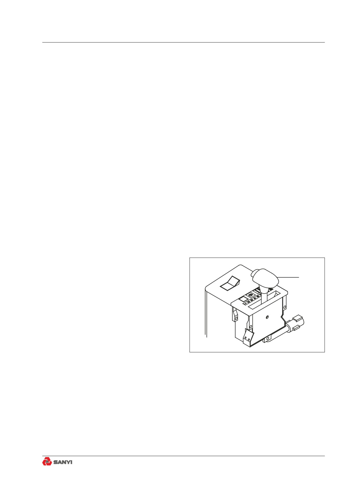
● When leaving the operator’s cab, place
gear shift lever (1) at Neutral, set parking
brake switch to PARKING, set the dump
● control lever to HOLD, then stop the
engine.
● Remove the key from the starting switch.
Fig. 2.2-6
● Lock all the doors of the operator’s
compartment.Take the key with you and
leave it in the specified place.
2-15
Safety
2.2.9 Handholds and steps
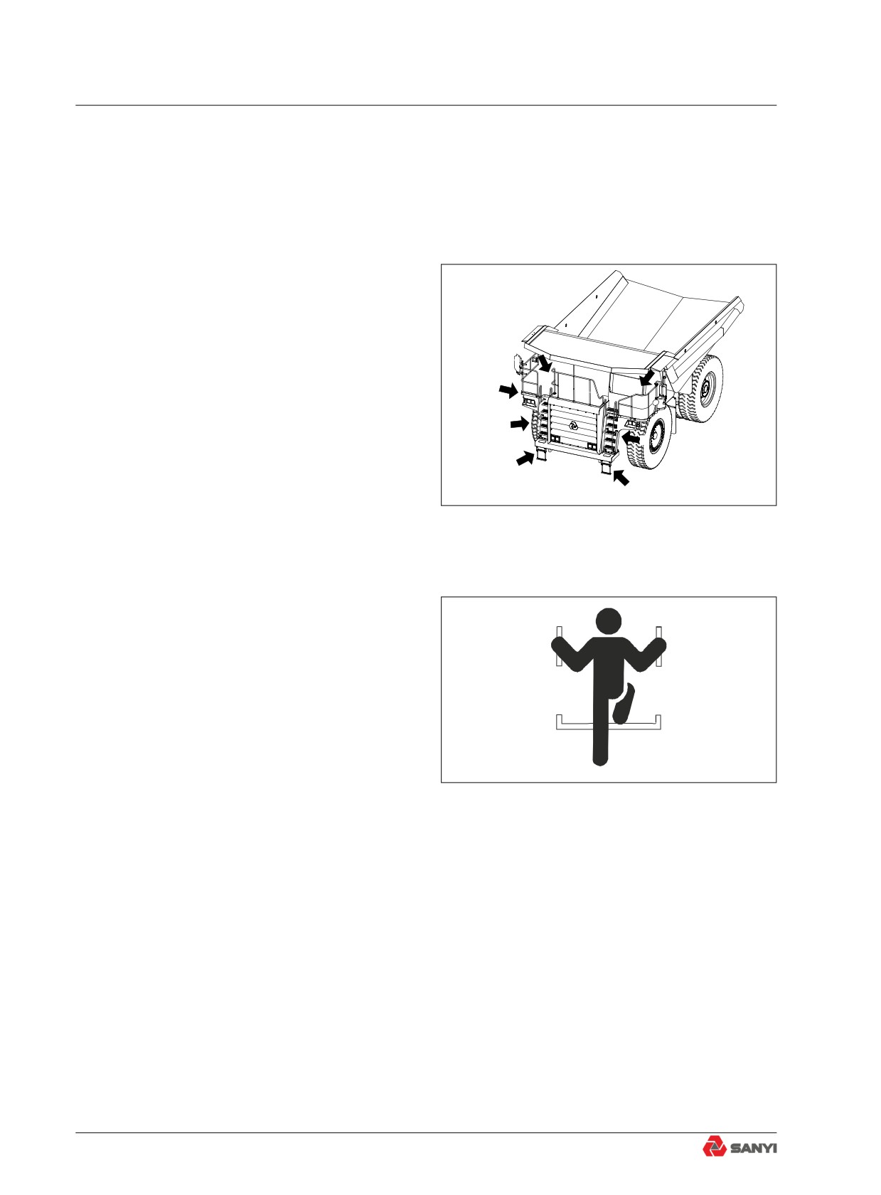
To avoid risk of injury when getting on or
off the machine.
●
Always face the machine and maintain at
least three-point contact (both feet and
one hand, or both hands and one foot)
with the handrail and steps to ensure that
A
you support yourself.
B
●
Always check the handrails and steps
A
for oil, grease, or mud. Wipe them clean
before using.
A
●
Repair any damage and tighten any loose
B
bolts.
A
●
Never get on or off the machine while
B
holding tools in your hand.
Fig. 2.2-7
●
Never climb onto the engine hood, covers,
or other places where there are no anti-
slip pads.
●
When entering the operator’s
compartment, never hold the dump control
lever. If the dump control lever is gripped,
it may move.
●
Never jump onto the machine. There is
danger that your feet will slip, and you will
fall and be seriously injured.
●
Never jump off the machine. There is
danger that you will break a bone or suffer
other serious injury when landing.
Fig. 2.2-8
●
Never get on or off a moving machine.
You may be unable to support yourself
with the handrail or steps, and fall from
the machine, suffering injury. Even if the
machine starts off with no operator on it,
do not jump on the machine and try to
stop it.
2-16
Safety
2.2.10 Preventing burns
2.2.10.1 Hot coolant
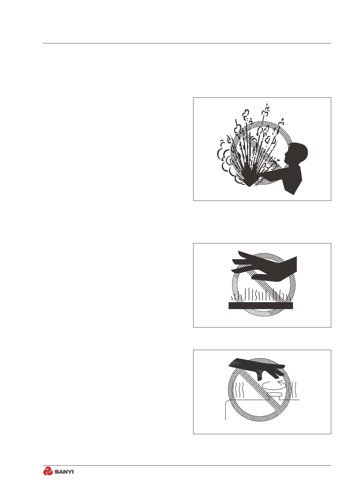
● To prevent burns caused by hot coolant or
steam when checking or discharging the
coolant, wait until the engine coolant is
cool enough before proceeding.
● Never open the cap of radiator before the
engine cools down. Loosen the cap of the
radiator slowly before removing it. Internal
pressure of radiator must be relieved to
avoid serious burns.
Fig. 2.2-9
2.2.10.2 Hot oil
● To prevent scalds caused by hot oil when
checking or discharging the oil, always
wait for the engine oil to cool down before
you proceed.
● When the engine has cooled down,
loosen the cover or screw plug slowly to
relieve internal pressure.
Fig. 2.2-10
Fig. 2.2-11
2-17
Safety
2.2.11 Preventing fire and explosion
2.2.11.1 Fire caused by fuel or oils
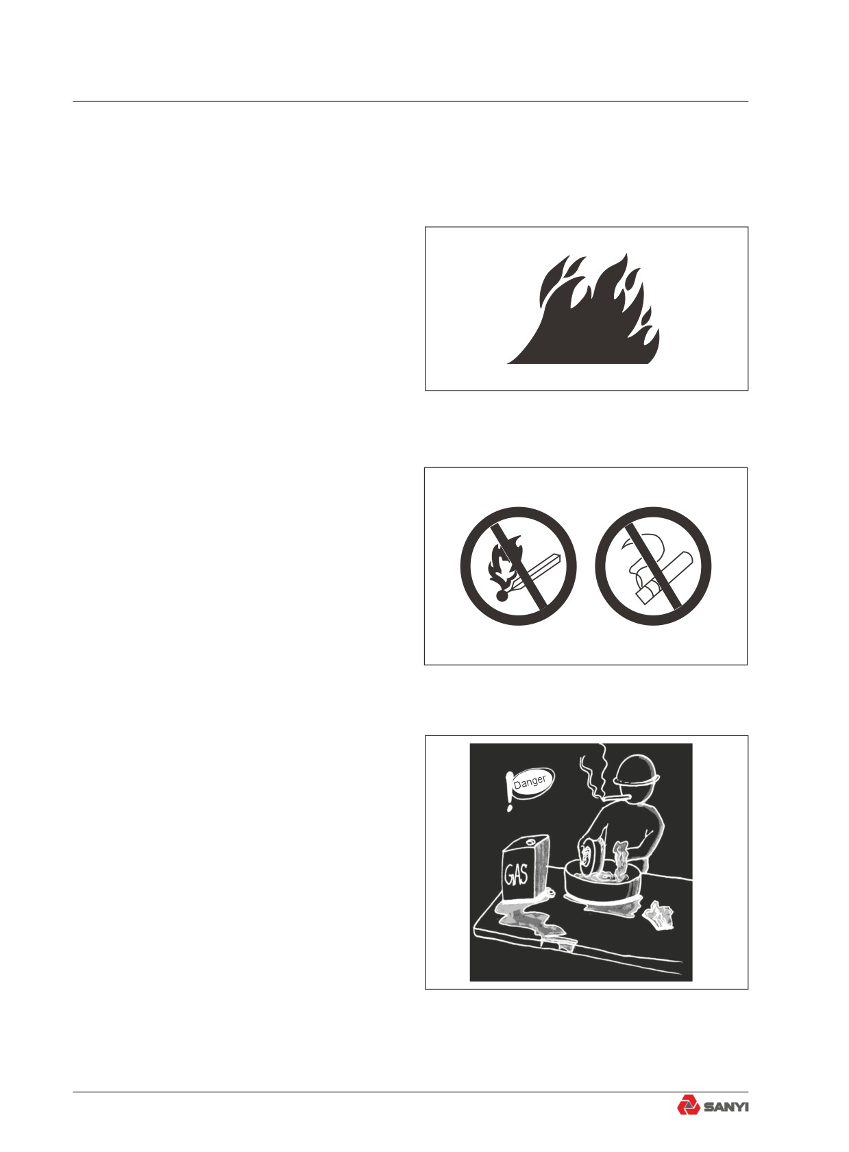
● Engine oil and fuel must be stored in
designated place, where unauthorized
persons cannot enter.
● Never smoke or use fire near fuel or
engine oil.
● Check for missing or loose pipe clamps,
twisted hoses, hoses rubbing against
pipeline,damaged oil cooler, and loose
bolts in flange of oil cooler, so as to avoid
Fig. 2.2-12
oil leakage.
● Tighten, repair or replace any
missing,loose or damaged pipe clamps,
pipelines,hoses, oil coolers or other flange
bolts.
● Refuel or store oils in a place with good
ventilation.
Fig. 2.2-13
Fig. 2.2-14
2-18
//////////////////////////////////////////