New Holland. Cab 2 WD / 4 WD TS-100A, TS-115A, TS-125A, TS-135A. ASSEMBLY MANUAL - page 3
NOTES
Maverick (NH TS-100A,115A , 125A, 135A Asy. Man) 01/05
Section 8 - 18
Section 9
MAVERICK
New Holland Tractor
TS-100A,115A, 125A, 135A
Boom & Head
Installation
Section 9 - 1
Boom / Head Installation
Boom Installation / Boom Hoses:
1.
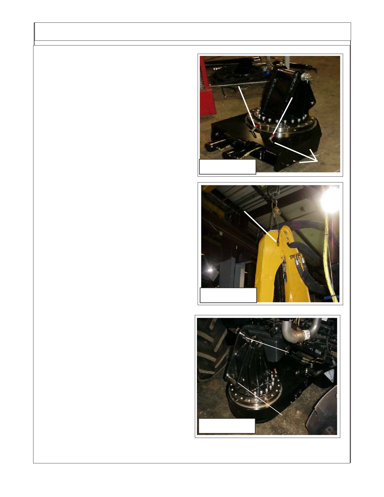
Turret Assembly, The turret assembly has
Swing Cyl. Hose
Swing Cyl. Hose
the cylinders connected and the hoses are con-
with Green /
with Green Tie
nected to the cylinders. The end of the hoses will
White Tie
be sticking up through the turret mount weldment
between turret and tractor. The hoses will need
to be connected there and routed to the hydraulic
control valve. One hose will have a Green Tie
and one a green and white tie where the come up
throught the turret mount weldment. (See Figure
3).
2.
Booms Are recieved from the factory with
the Sections of Boom Assmebled to together.
Figure 1
Rear of Tractor
The Boom Sections are assembled with the hy-
draulic lines and cylinder connected. The hose
will be connected to the boom that are routed to
the control valve and diverter valve and bundled
together.
(See Figure 4). The Boom Hoses are
Lifting
protruding out the turret mount end of the boom.
Point
The Hose connections on the head end will be
shipped with metal caps on them, these are to
protect the lines from contamination and should
not be removed until the hoses are being in-
stalled (See Figure 5). The hose that attaches to
the boom are sent installed on the head assem-
bly and the hose will also have plugs in them.
3.
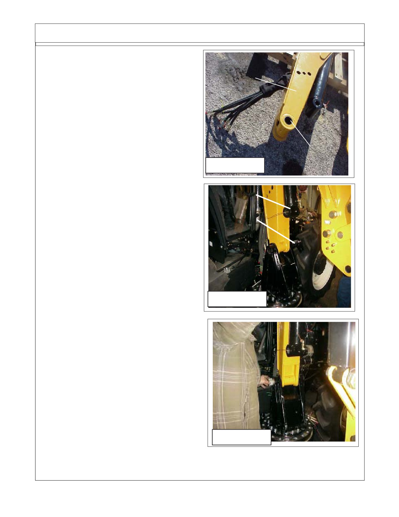
Boom Lift Cylinder. The boom lift cylinder
Figure 2
will be connected to the boom at the rod end of
the cylinder (See Figure 2 & 4) when it is shipped
from factory. The hoses will also be connected to
the cylinder. The retaining pin for the lift cylinder
will be located in the turret assembly. The Lift
Cylinder will be fastened to boom with tie wire. It
will not be required to remove this tie wire before
Main Boom
mounting boom on turret assembly. -
Mount Pin
4.
Booms & Lift Cylinder Mounting Pins.
The Boom and lift cylinder mounting pins are
shipped installed in the turrert assembly. Re-
move both pins in preparation to mounting the
boom. (See Figure 3)
Lift Cyl. Base
End Mount Pin
Figure 3
Section 9 - 2
Boom / Head Installation
5.
Lower Boom onto Turret Assembly. Us-
ing an over head hoist lift the boom by placing a
Turret End
lift strap at the boom hinge point (See Figure
Of Boom
2), the boom assembly will be shipped with the
two boom end tie wired together (See Figure
3A). The wire tie will need to be removed as it
is tied through the boom hinge pin hole. Lift the
boom above the turret assembly and lower it
back down onto the turret assembly aligning
the boom with the mounting pin hole. Install the
Boom Mounting
Mount Pin through the turret and into the
Pin Hole
boom. Make certain the pin is installed cor-
Figure 3A
rectly as one side of the pin is self locking in
design. Tighten the pin retaining nut and install
cotter pin. (See Figure 3C)
Lift Cylinder
6.
Connect lower end of Lift Cylinder. The
Base end (lower end) of lift cylinder will mount
Mount Pin
into the turret under the boom mount. The Cyl-
inder will have to be extended to connect, If
cylinder has to be extended the best way is to
unplug the ends of the lift cylinder hoses where
they come out of the boom, these will be the #
6 hose with the Orange Tie and the # 6 hose
with the orange / White Tie. When pulling (ex-
tending or collapsing cylinder) always put the
opened end of the hoses into a clean drain pan
as oil will run out of the cylinder when extended
Figure 3B
or collapsed. After installing the cylinder lower
mounting pin re-plug the hoses that were in the
drain pan until ready to connect hoses.
7.
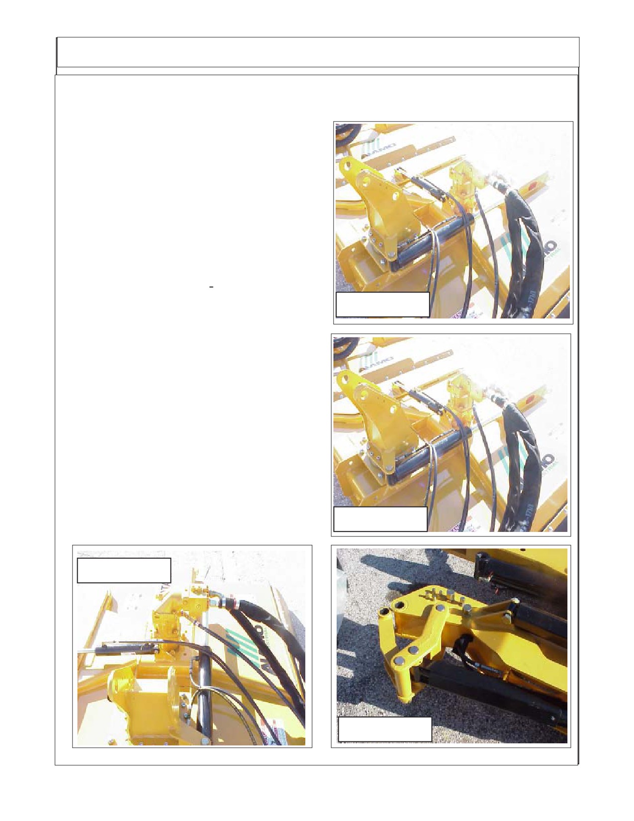
Connect Head to Boom. The mounting
pins to install the head onto the boom will be
shipped installed in the mount weldment. Re-
move the mounting pins. Use the hoist to lower
boom down over head to connect head, Align
the upper head mount pin. The lower mount
pin is the connect the lift link.
(See Figure 4 &
5). The Door Cylinder and the Swivel Cylinder
are shipped installed on the head with the
hoses connected to the cylinder.
Figure 3C
Section 9 - 3
Boom / Head Installation
8.
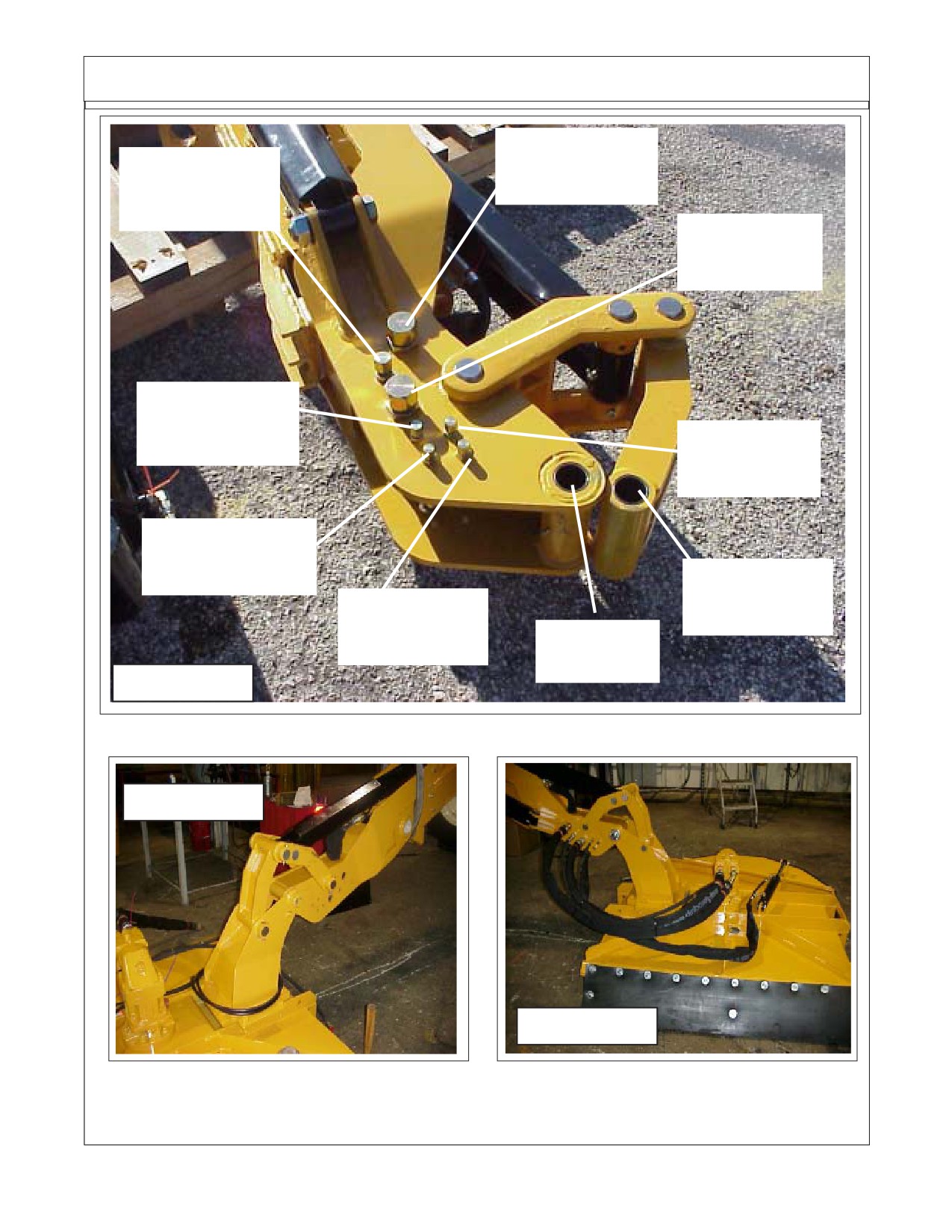
Heads Are received from the Factory with
the Cylinder and Head hoses Attached to Head.
The head will be received with the door cylinder,
swivel cylinder and Motor attached to the head.
60 Inch Head with
The Hoses for the cylinders and the motor will
Swivel Hitch Mount
connect to the boom. There is a decal that is
installed on the side of the boom that shows
where the hoses connect to the fitting that have
the metal caps on them. The fittings for the head
are located on the side of the main Boom. The
hoses must be connected in the correct order to
make certain of correct operation (See Figure 4,
5, 6, 7, 8, 9 & 10).
9.
Two Head Options. There are two heads
available, 60" (See Figure 4,5 & 6) which has the
Figure 4
head Swivel attachment on it. The 50" Head which
will not have the swivel attachement (See Figure 9
& 10) If using the 50" head leave the ports for
swivel cylinder on boom capped (See Figure 8)
60 Inch Head with
Swivel Hitch Mount
10.
Connect Hose From Boom to Control
Valve. The cylinder hoses will connect to the
control valve mounted on the front of the tractor
with the exception of the Door and Swivel Cylinder
hoses they will connect to the diverter valve and
then there are two hoses that connect to
thediverterr valve to the 6 spool control valve (See
Figure 11). The hoses for door and swivel will be
routed under the tractor along the center under
frame weldment to the diverted valve which will be
Figure 5
mounted on the LH side of the tractor on the front
frame mount bracket.
60 Inch Head with
Figure 6
Swivel Hitch Mount
Figure 7
Section 9 - 4
Boom / Head Installation
Motor Tank Return
Motor Case Drain
#16 Hose
#12 Hose
(Orange Tie)
(Blue Tie)
Motor Pressure
# 16 Hose
(Red Tie)
Door
Cyl. # 4 Hose
(Yellow / White Tie)
Door
Cyl. # 4 Hose
(Yellow Tie)
Swivel
Cyl. # 4 Hose
(Green / White Tie)
Head Lift Link
Pin Hole
Swivel
Cyl. # 4 Hose
Head Mount
(Green Tie)
Pin Hole
Figure 8
Figure 9
50 Inch Head w/o
Swivel Hitch Mount
50 Inch Head w/o
Swivel Hitch Mount
Figure 10
Section 9 - 5
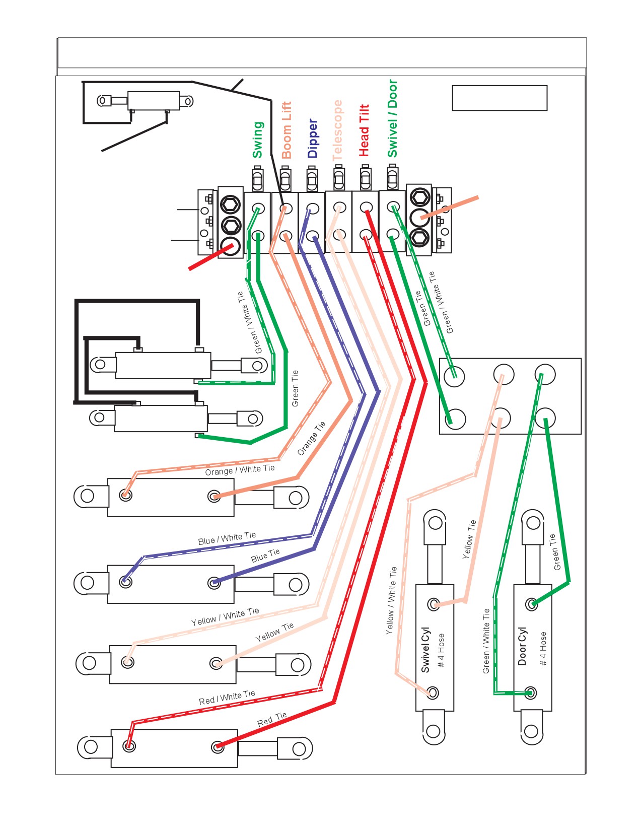
Boom / Valve Hydraulic Schematic
Tees into Lift
("B" Port)
Hose (No Plastic Tie)
Stabilizer Cyl
Figure 11
# 4 Hose
6 Spool Control Valve
Returns to same port on
tan as Oil cooler Hose
1
1
Tank Return
"B" Ports
(Orange Tie)
1
12
1
12
"A" Ports
Pressure Supply
(Red Tie)
No Colored Ties only Hose
Bands P/N 02981825
Diverter Valve
Swing Cyl
# 6 Hose
C2
C1
P1
Swing Cyl
P2
C3
C4
# 6 Hose
Boom Lift Cyl
# 6 Hose
Dipper Cyl
# 6 Hose
Telescope Cyl
# 6 Hose
Head Tilt Cyl
Section 9 - 6
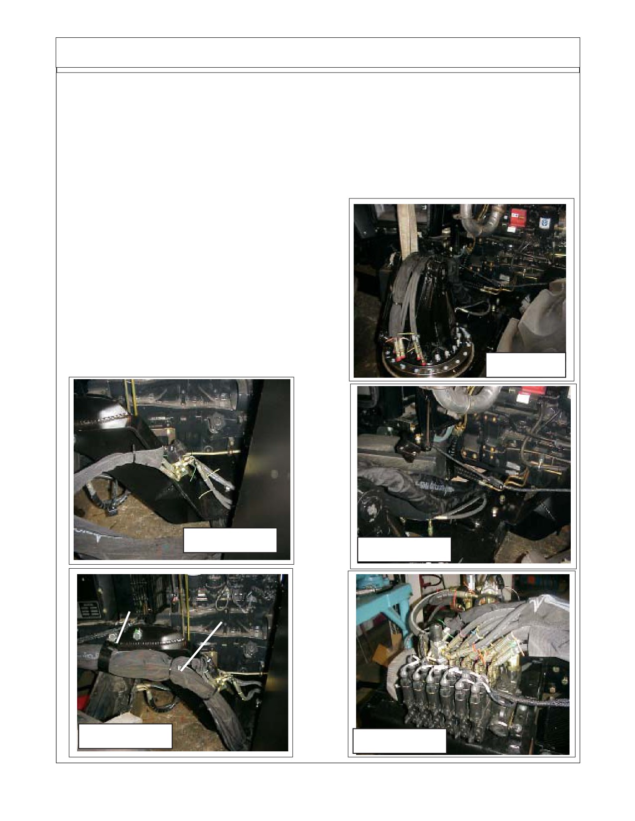
Boom / Head Installation
11.
Routing Cylinder Hoses from Boom to Valve The Hose from the boom to the valve will be
split, the four hoses to the door cylinder and swivel cylinder will run together through a section of
sleeving material to the RH side of the tractor (See Figure 12). On the Right hand side of the
tractor the four hoses will connect to the diverter valve in the coded locations (See Figure 11). Tie
the hoses to the frame under the tractor (See Figure 13). The two hoses from the diverter valve will
continue along the LH side of tractor with sleeving material over them (See Figure 13) to the front
of the tractor. They will have hose support brackets on them that bolt to the side of the tractor (See
Figure 13) where they will be connected to the valve at the Door / Swivel Ports in the correct order
(See Figure 16 & 17).
The other cylinder hoses from the boom will
be inserted into sleeving material and also be routed
under the tractor to the LH side (See Figure 14). They
will continue up the LH side to the front of the tractor
where they will connect to the valves ports. The
hoses will be held to the frame with metal hose hold-
ers bolted to the tractor frame (See Figure 15).
NOTE: the hoses must be run through the
sleeving material. On the LH side there is a hole in the
center frame weldment the hoses can be run through
it if wanted. Connect the hoses to the valve as shown
(See Figure 11 & 17)
Figure 12
Figure 13
Figure 14
Hose Support
Sleeving Material
Bracket
for Hoses
Figure 15
Figure 16
Section 9 - 7
Hydraulic Hose Connections
HYDRAULIC HOSE CODES AT VALVE
Hydraulic Hose Band Mark Color Codes: Hose's and/or fittings are marked with a
Color Coded Plastic Band around it. Some Bands are a solid Color and some are Colored with a
Stripe. The purpose of the colored bands are to provide a quick reference for hose and port
connection. A metal band is also attached to the hose, on that band is an Alamo Industrial Part
Number for reference if needing a replacement hose. Always Check Hose Size, Color Code
& Part Number
(See Figure 4)
Boom Cylinder Circuit Hoses:
Color Tie
(Code) Hose Size Port Diverter Hyd. Function
Green
G
SAE # 6
A
---
Swing, Back (Rod End)
Green / White
G/W
SAE # 6
B
---
Swing, Forward (Base End)
Orange
OR
SAE # 6
A
---
Lift, Down (Rod End)
Orange / White
OR/W
SAE # 6
B
---
Lift, Up (Base End)
Blue
B
SAE # 6
A
---
Dipper, In (Rod End)
Blue / White
B/W
SAE # 6
B
---
Dipper, Out (Base End)
Yellow
Y
SAE # 6
A
---
Telescope, In (Rod End)
Yellow / White
Y/W
SAE # 6
B
---
Telescope, Out (Base End)
Red
R
SAE # 6
B
---
Head Tilt, Up (Rod End)
Red / White
R/W
SAE # 6
A
---
Head Tilt, Down (Base End)
Green
G
SAE # 4
A
P2
Control Valve tor Diverter valve
Green / White
G/W
SAE #4
B
P1
Control Valve to Diverter Valve
Green
G
SAE # 4
---
C4
Swivel, CW (Rod End)
Green / White
G/W
SAE # 4
---
C1
Swivel, CCW (Base End)
Yellow
Y
SAE # 4
---
C3
Door, Open (Rod End)
Yellow / White
Y/W
SAE # 4
--
C2
Door, Closed (Base End)
Orange
OR
SAE#12
T
---
Valve Return To Tank
Red
R
SAE#12
P
--
Pressure to Valve.
Motor Circuit Hoses to Boom Connections: (Listed as reference)
Color Tie
(Code) Hose Size
Hyd. Function
Red
R
SAE # 16
--
Pressure Flow to Motor
Orange
OR
SAE # 16
--
Return Flow From Motor
Blue
B
SAE # 8
--
Case Flow From Motor to Boom
Blue
B
SAE # 12
--
Case Flow at Boom to Tank
Diverter Valve.:
The Diverter Valve bolts onto the front frame mount bracket on the LH side of the tractor, the holes
are in the bracket (See Figure 5 & 6). The Diverter valve is a electrical operated valve that allows the
hydraulic pressure to be shared to operate two (or more if valves are stacked) functions with a single
pressure supply. This valve is strictly a diverter valve and is designed to direct the pressure, not regulate
the flow or pressure.
The Port openings on this diverter valve are marked with letter number codes which show which
port is connected to which hose and where that hose connect on other end (See Figure 4, 5 & 6))
Port
Function & Connection
P1
Hose Hydraulic Pressure from Door / Swivel (B) Port on Control Valve (G/W Tie)
P2
Hose Hydraulic Return to Door / Swivel (A) Port on Control Valve (G Tie)
C1
Hose to Head Swivel Cylinder Base End (G/W Tie)
C2
Hose to Door Cylinder Base End (Y/W Tie)
C3
Hose to Door Cylinder Rod End (Y Tie)
C4
Hose to Head Swivel Cylinder Rod End (G Tie)
Section 9 - 8
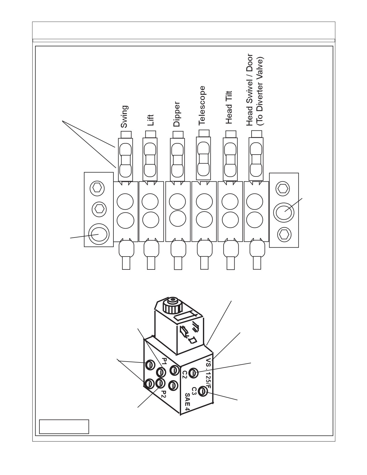
Hydraulic Hose Connections
Six Spool Control Valve
External Wire Connec-
tions for valve are marked
"A" and "B" on Valve &
AA1 thru AA12 on wire
harness connections
B
B
B
B
B
B
AA
AA
AA
AA
AA
AA
12
10
8
6
4
1
AA
AA
AA
AA
AA
AA
11
9
7
5
3
2
A
A
A
A
A
A
"B"
"B"
"B"
"B"
"B"
"B"
OR/
Return
Y/W
R
G/W
G/W
B/W
W
To Tank
"T"
B
Y
R/W
G
OR
G
Pressure
"A"
"A"
"A"
"A"
"A"
"A"
Supply
Port "P"
Diverter Valve
Diverter Valve "C1" Port
to Swivel Cyl Base
End Port (G/W Tie)
Valve "B" Port to
Diverter valve P1 Port
Diverter Valve "C4" Port
(G/W Tie)
to Swivel Cyl Rod End
Port (G Tie)
4 Through holes are
Diverter Valve "C2" Port
mounting holes
to Door Cyl Base End
Port (Y/W Tie)
Diverter Valve "C3" Port
Valve "A" Port to
to Door Cyl Rod End
Diverter valve P2 Port
Port (Y Tie)
(G Tie)
FIGURE 17
Section 9 - 9
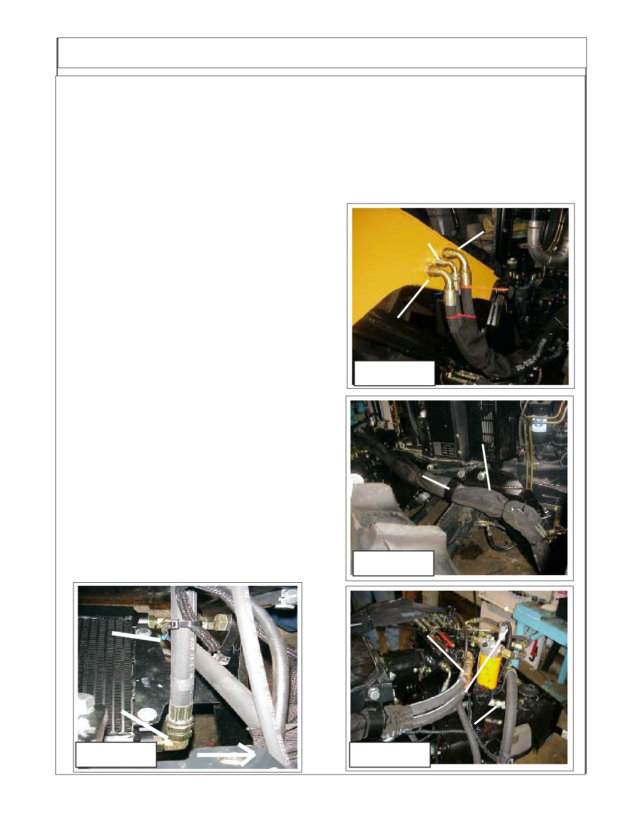
Boom / Head Installation
12.
Routing Boom Hoses to Pump The Boom hose to the pump will be routed on the RH Side
of tractor, They will be run through sleeving material and hose support bracket (See Figure 18).
The Pump hoses must be connected correctly to the boom and pump. There are 2 Pump to motor
hoses and 1 motor case drain return hose for a total of 3. (Note Motor Case Drain hose will be run
through the Oil Cooler and then return to tank).
First is the # 20 hose with the red plastic tie the lower connection at Boom, (See Figure
17), this is the pressure supply from the pump lower connection at pump (See Figure 20) to the
motor connection at the boom.
Second is the # 20 hose with the orange plas-
tic tie the upper connection at boom (See Figure 17).
Orange Tie
This is the Return hose from the motor upper connec-
Blue Tie
tion at pump (See Figure 20).
Third is the # 16 Hose with the blue plastic tie
the middle connection at the boom (See Figure 17)
which is the case drain from the motor. This hose
connects to the Oil Cooler / Fan Assembly which is
mounted under tractor bolster behind hydraulic tank
(See Figure 19) . There is a short #16 hose (See
Red Tie
Figure 19) which will not have a plastic tie on it that
will connect to the oil cooler, and then goes to the tank
to a return port (See Figure 20).
Figure 17
13.
Pump Hose Routing at Tank. The hose routing
at tank is shown as reference to the Pump hose
Sleeving Material
routing which most of will already be connected when
for Hoses
the tank and pump assembly is shipped from the
factory. All hoses that you must disconnect and re-
Hose Support
connect during pump and/ or tank assembly, refer to
Bracket
this figure for the correct location of hose (See Figure
21). DO NOT start tractor before all steps of the
installation is completed, if tractor is started damage
to the hydraulic system will occur.
Figure 18
Hose From Boom
Red Tie
(Motor Case Drain)
Orange Tie
Blue Platic Tie
(Bottom Fitting)
(Top Fitting)
Hose From Oil
Cooler to Tank
return, No Plastic
Tie
RH Side
No Tie (F/ Oil
of Tractor
Cooler to Tank)
Figure 19
Figure 20
Section 9 - 10
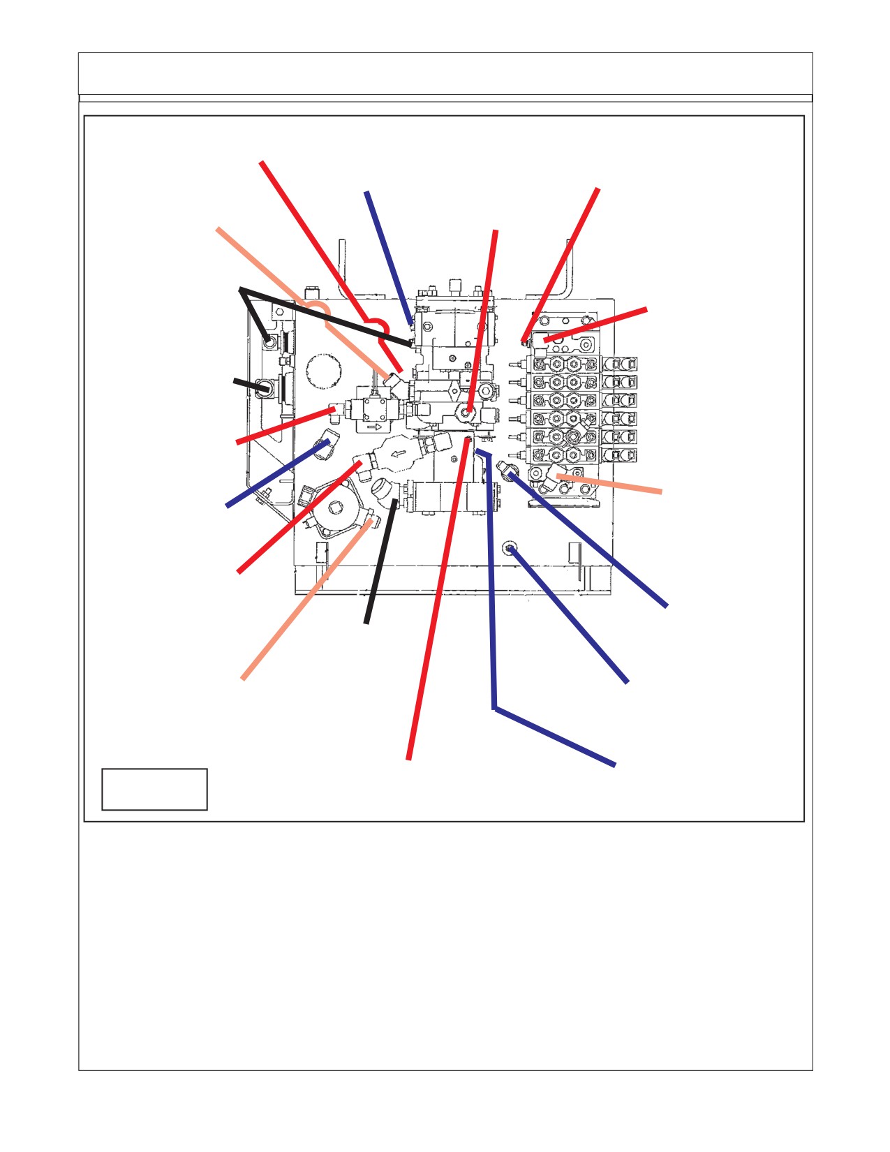
Hydraulic Tank Hose Routing
"J" # 16 Hose
"B" # 8 Hose
(Red Plastic Tie)
(90° Elbow)
"E" # 4 Hose
(Blue Plastic Tie) "A" # 8 Hose
(Red Plastic Tie)
"K" # 16 Hose
(90° Elbow)
(Orange Plastic Tie)
(Red Plastic Tie)
"C" # 12 Hose
Suction Hose
"D" # 12 Hose
(No Plastic Tie)
(Red Plastic Tie)
"G" # 20 Hose
Suction Hose
(No Plastic Tie)
"A" # 8 Hose
(Red Plastic Tie)
"H" # 12 Hose
"L" # Hose
(90° Elbow)
(Blue Plastic Tie)
(Orange Plastic Tie)
"D" # 12 Hose
(Red Plastic Tie)
"B" # 8 Hose
(Blue Plastic Tie)
"G" # 20 Hose
Suction Hose
(No Plastic Tie)
"F" # 4 Hose & Tee
"H" # 12 Hose
Tank Return
(Orange Plastic Tie)
(Blue Plastic Tie)
"F" # 4 Hose
"E" # 4 Hose (90° Elbow)
(90° Elbow)
Figure 21
(Red Plastic Tie)
(Blue Plastic Tie)
NOTE: Hoses are not shown in drawing above, this is for clarity. The hose routing is for the hoses which
connect from one point to the other. Use the instructions and hose description listed to follow hose
routing.
Example: Hose - A connects to one end marked A and the other end of hose connects to the other item
marked A. This is done with the other letters as well, the hose must connect to the same letter markings
on each end as in drawing. Some hose will be marked with a colored plastic tie.
Some hose will have a straight fitting or a 90° fitting. This is to allow hoses to be routed to where they
clear other items, when connecting hose put the end on that has the correct fitting as noted in drawing
with (90°) or the straight fitting if note marked hose routing that is to make hoses clear other items. Do
Not connect hose to different letter items, all hose end must connect to the same letter on both ends.
TO ID HOSES: Always check Size, Length, Fittings and Color Plastic Tie to identify the hoses. Some
hoses will have the same color tie but the size, length or fittings will be different.
Section 9 - 11
MOTOR & BOOM PUMP - HOSE ROUTING
Listed Below are the location, part number , hose size / type and function of the hoses at the tank, this
list is to be used with figure 21 as a reference.
Item Part No.
Qty. Description
A
02981427
1
Hose, 8FJX - 8FJX 90° - 24" Lg. w/Red Tie (Charge Filter to Pump)
B
02981428
1
Hose, 8FJX - 8FJX 90° - 21" Lg. w/ Blu Tie (Case Drain to Tank)
C
02981429
1
Hose, 12FJX - 12FJX - 23" Lg. (Pump to Suction Filter) hose under
pump and cannot be seen in drawing.
D
02981430
1
Hose, 12FJX - 12FJX - 31" Lg. w/ Red Tie (Pressure Filter to Supply)
E
02981431
1
Hose, 4FJX - 4FJX 90° - 35" Lg. w/ Red Tie (Pump Load Sense to Valve (PX)
Connects to top side of pump as shown.
F
02981432
1
Hose, 4FJX - 4FJX 90° - 20" Lg. w/ Blu Tie (Pump Regulator to Tank)
Connects to bottom side of pump not seen.
F
-------------
1
Hose #4, Connects here w/ Tee Fitting (Connect to Base End Stabilizer Cyl)
G
02981433
1
Hose, 20FJX - 12FJX - 24" Lg. (Pump to Suction Filter)
H
02981462
1
Hose, 12FJX - 12FJX 90° - 20" Lg. w/ Org Tie (Valve Return to Tank)
J
-------------
1
Hose, # 16 w/ Red Tie (Pressure from Pump to Motor) Bottom Port
K
-------------
1
Hose, # 16 w/ Orange Tie (Oil Return from Motor) Top Port
L
-------------
1
Hose. w/ Blue Tie (Oil Return from Oil Cooler to Tank)
Section 9 - 12
Section 10
MAVERICK
Fill Oil Tank
Electronic Controls Setting
New Holland Tractor
TS-100A, TS-115A
TS-125A, TS-135A
New Holland (NH TS-100A, 115A, 125A, 135A Asy. Man) 01/05
Section 10 - 1
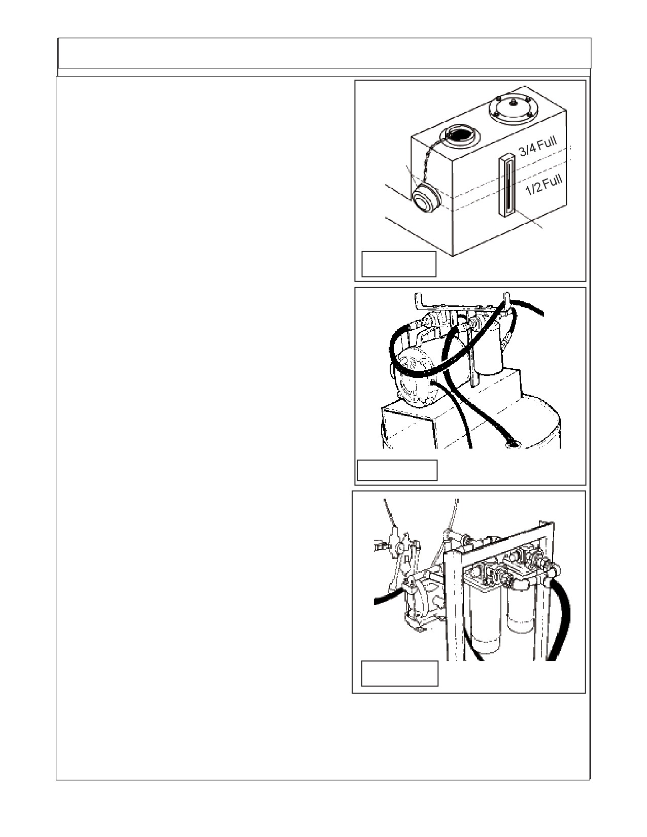
Hydraulic Oil Installation 2 WD & 4 WD
Hydraulic Tank Filling:
1.
Filling With Recommended Hydraulic Oil. The oil
used MUST MEET the requirements as to type and
cleanliness level, THIS IS A MUST. The oil must be type
Fill
ISO Grade Hydraulic Oil w/ protection wear grade
Cap
based on abient temperature (See Decal Figure 4).
The grade of oil will vary with the ambient twmperature.
The Fluid Cleanliness level MUST BE ISO 16/14/11
rating. MAKE CERTAIN that the oil you are using meets
this requirement. If Oil does not test to cleanleness
Sight
reguirement, it will have to be filtered to clean it before
Gauge
installing it into the maverick hydraulic system. NEVER
Figure 1
install or add Oil that does not meet these stadand
requirenments.
2.
Remove the Filler Cap and fill the Hydraulic
Tank, Make certain the oil is ISO AW 100 Hydraulic
Fluid with cleanliness level of ISO 16/14/11 is a must,
however do not over fill or spill oil.
3.
Check that all the hydraulic connections are
complete and tightened on the Motor Hydraulic Sys-
tem and the Cylinder Hydraulic System.
4.
Avoid hydraulic contamination by filtering the hy-
draulic oil while filling the hydraulic tank. Filter buggies
or carts are commercially available for Pre cleaning oil
before it is installed or hydraulic system cleanup. These
consist of a high-efficiency, high-capacity filter, a circu-
Figure 2
lating pump, a drive motor, and hoses for connecting to
oil supply.
(See Figure 2 & 3)
When adding hydraulic oil, use only new oil from
a sealed barrel. Used oil or oil from an open barrel may
contain high levels of contamination. Transfer the new
oil into the hydraulic tank by using a hydraulic filter pump
unit equipped with a properly operating micron filter to
achive rquired cleanleness level is a must. This will
insure that the oil being added is safe to use. Do not just
pour the oil directly into the hydraulic tank since most
oils (even from a sealed barrel) have contaminants that
should be removed, before operating the hydraulic sys-
tem. (See Figure 2 & 3).
4.
Important: Change the return filter in tank and
Figure 3
suction filters at recommended hours of operation
(See Operators Manual for maintenace schedule). The only hydraulic oil to be used is the AW
ISOAW Tractor Hydraulic Oil (See Figure 4 for oil Grade ) with a cleanliness level of ISO16/14/
11. Always use a good Filter Maintenance program and Oil cleaning system before adding any oil
to system..
New Holland (NH TS-100A, 115A, 125A, 135A Asy. Man) 01/05
Section 10 - 2
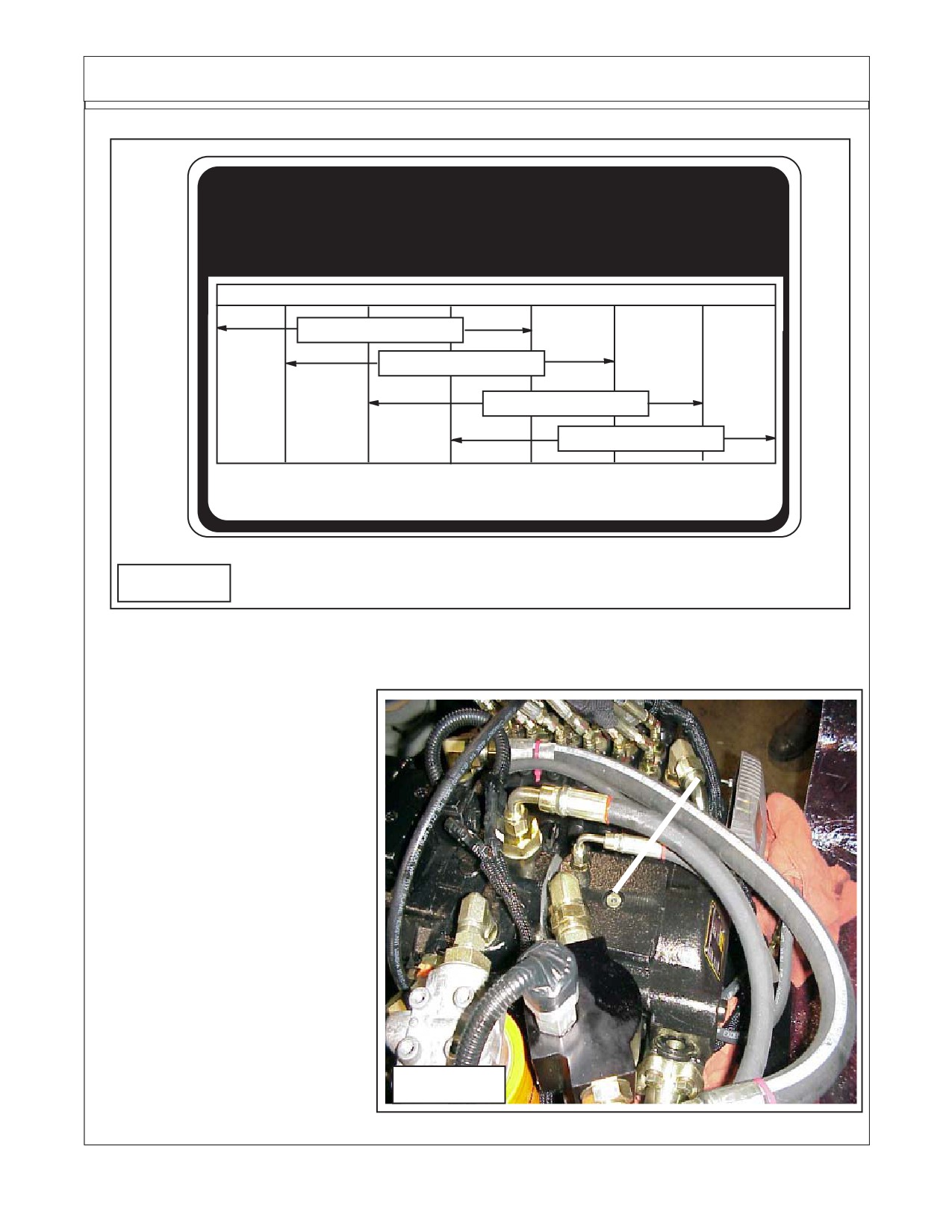
Hydraulic Oil Installation 2 WD & 4 WD
ATTENTION
10°F 20°F
30°F
40°F
60°F
70°F
90°F
110°F
AW ISO VG 32
AW ISO VG 46
AW ISO VG 68
AW ISO VG 100
The correct hydraulic fluid is dependent upon ambient
temperature. Refer to chart when selecting proper grade
02982828
Figure 4
Prime Hydraulic Pump:
1.
The Hydraulic Pump
MUST be Primed. The hy-
Remove This allen head
draulic pump is primed by putting
plug to Prime Pump
oil directly in to the pump. Looking
at the pump, out near the end of the
pump there is a Allen plug (See
Figure 5). Remove this plug and
install only approved hydraulic oil (
See Step 1 through 3 of hydraulic
tank filling). Fill the cavity completely
full up to plug threads. IMPOR-
TANT! This must be done before
the unit is ever started. Make cer-
tain that the O-Ring Seal is on plug
and reinstall it after cavity is full of
oil, now the pump is primed. The
Unit still will not operate until the
next step of setting the electronics
Figure 5
to operate the system.
New Holland (NH TS-100A, 115A, 125A, 135A Asy. Man) 01/05
Section 10 - 3
CONTROL VALVE - BOOM & MOTOR CONTROL
Maverick Boom and Motor Control Circuits:
It is advised that this section be read before proceeding with any repairs or test,
with the display and electronics used in this application the system will test many
components for you. This is done by following the prompts on the display screen.
DO NOT pressure wash this system, while the components are sealed the soaps, acid and
high water pressure used in the pressure washer can damage these seals and cause moisture
to enter system causing damage.
DO NOT do any welding around these electronic components, If welding is required in a
repair the electronic components MUST be disconnected (unplugged). Un plug all components,
Joystick, Modules, Displays and any other electronic component. If not unplugged the current from
the welded can cause serious damage to electronic components.
Additional repair and diagnostic procedures for the electrical system is available on the
internet web site of the manufacture of this system at: REFERENCE PRODUCT MANUAL FOR
MDM DISPLAY. THIS MANUAL IS AVAILABLE FROM THE MANUFACTURER ON THE
INTERNET AT www.iqan.com viewable and printable with ADOBE ACROBAT READER. If
that the instructions you refer to is for the MDM system, the manufacturer has more than one
system.
The boom and motor control is electronic over hydraulics. If these functions are not
properly set or working properly the mower can not be operated. Also make certain that all fluid
levels are OK and with in operating limits.
The first thing that should be checked is the main (electrical) power supply to the system,
this can be checked on the display unit when power is on.
The set-up portion as shown in the next pages should be checked to make certain the
joystick and motor functions are set correctly. Check all the connections if not operating properly.
If the settings are not correct the system will not function properly.
Check the emergency stop (E-Stop) switch if it is in the off position the system will not
operate and the system cannot be set properly.
Never short across any of these components as the type electronics used can be
seriously damaged. Always use a volt / ohm meter to test any circuits.
New Holland (NH TS-100A, 115A, 125A, 135A Asy. Man) 01/05
Section 10 - 4
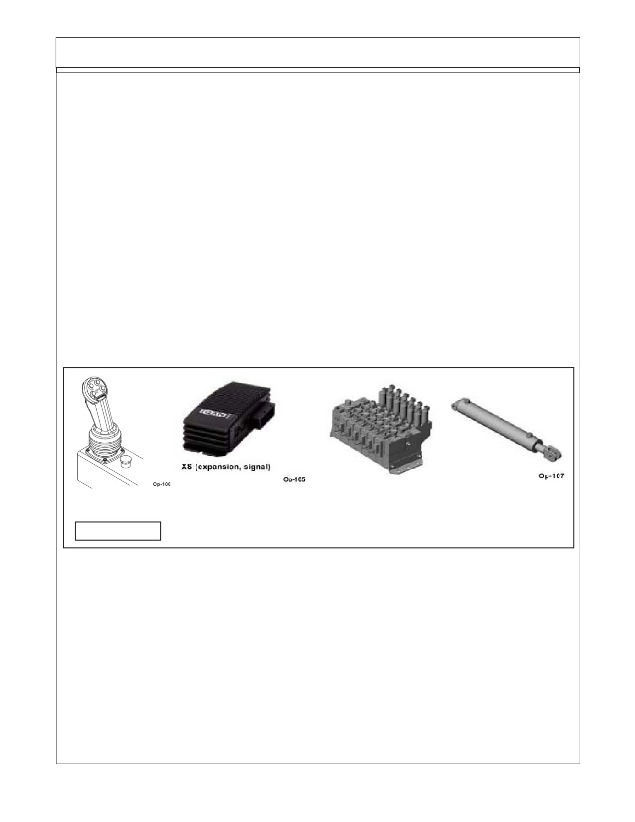
CONTROL VALVE - BOOM CONTROL
Maverick Boom Control System:
1.
Operating the Boom Control functions is done so by means of a load sensing electronic
over hydraulic system. There are three main areas of that system, the electronic network,
instrumentation and hydraulic components.
2.
System components are, The hydraulic System, The electronic network, The instrumen-
tation and Operator Interface.
3.
The Hydraulic System, The hydraulic components are responsible for transferring me-
chanical power into hydraulic power. There are two separate hydraulic circuits, the boom circuit
and the mower head circuit.
4.
How the boom is controlled, The system progression starts with operator input at the
joystick (Figure 6- Item A) or other instrumentation. Input is received at the CAN module (Figure
5- Item B) and joins the network. That information is transferred via the network to the valve solenoid
(Figure 5- Item C) which activates and moves the spool sending hydraulic fluid pressure to the
cylinder (Figure 5-Item D) and moves the load.
Item -C
Item -D
Item-A
Item-B
FIGURE 6
Maverick Mower Head Circuit:
1.
The Motor Circuit. The motor circuit for the cutting head operation is operated through
display (Figure 6- Item A). By selecting the activation parameter the coil will shift the servo-piston
at the hydrostatic pump (Figure 7-item B), stroking the pump into the "On" position. Flow will then
be supplied to the hydraulic motor at the cutter head (Figure 6-Item C). Activate the motor circuit
while the engine RPM is at idle. Once activated, the engine RPM can be raised to the 540 PTO
required speed, if the 540 PTO engine speed is not noted on the tractors RPM gauge consult tractor
owners manual to find what the required speed is. At any time the Emergency stop switch (Figure
7-Item D) located on the joystick will deactivate the cutter motor circuit. The blade will stop within
6 second when the emergency switch is shut "Off"
New Holland (NH TS-100A, 115A, 125A, 135A Asy. Man) 01/05
Section 10 - 5
CONTROL VALVE - ELECTRONIC NETWORK
Maverick Mower Head Circuit: (continued from Previous page)
Item
-A
Item -B
Item -C
Item -D
FIGURE 7
Maverick Electronic Network:
(Figure 8)
Electronic Network. The electronic network is the control and communication network that
receives and transmits data to certain components in the boom control system. Its purpose, is to
manage the incoming and outgoing information.
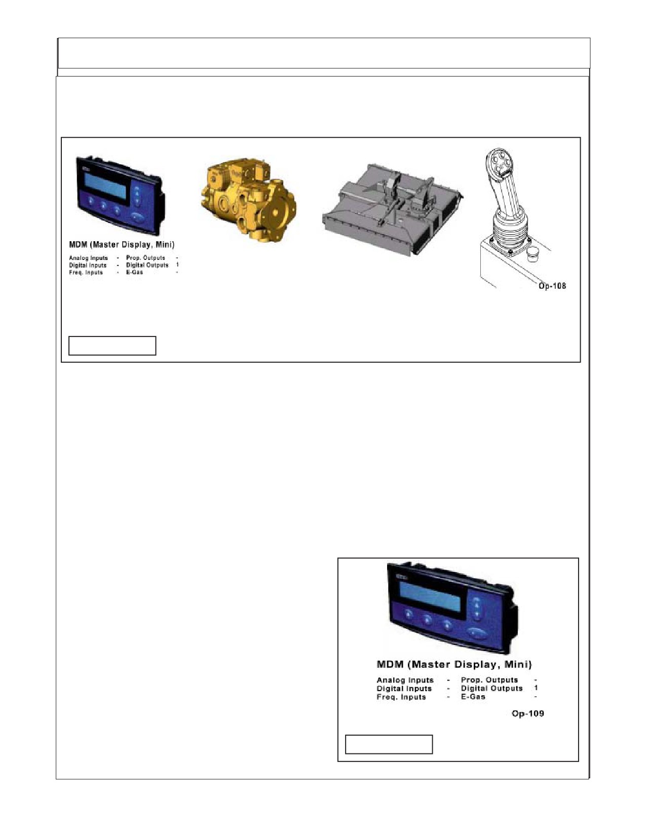
There are five main components. The MDM is an operator Display that is located in the cab.
The purpose of the display is to house the programming software for the system control and
provide an interface between the operator and the Maverick Boom.
The interface is utilized through a multi-screen function that allows the operator to set
individual parameters for customized control functions.
The display also provides tools such as an
on board measurement device, useful for determin-
ing short circuits, component loss, and/or power
supply issues. REFERENCE PRODUCT MANUAL
FOR MDM DISPLAY. THIS MANUAL IS AVAIL-
ABLE FROM THE MANUFACTURER ON THE
INTERNET AT www.iqan.com viewable and print-
able with ADOBE ACROBAT READER. If you do
not have Adobe Acrobat Reader it can be ob-
tained at www.adobe.com.
Make certain to view the MDM section as this
is the type used on the maverick boom, there are
listings at the web site that will not apply to the
FIGURE 8
maverick boom.
New Holland (NH TS-100A, 115A, 125A, 135A Asy. Man) 01/05
Section 10 - 6
CONTROL VALVE - ELECTRONIC NETWORK
Maverick Electronic Network:
( continued)
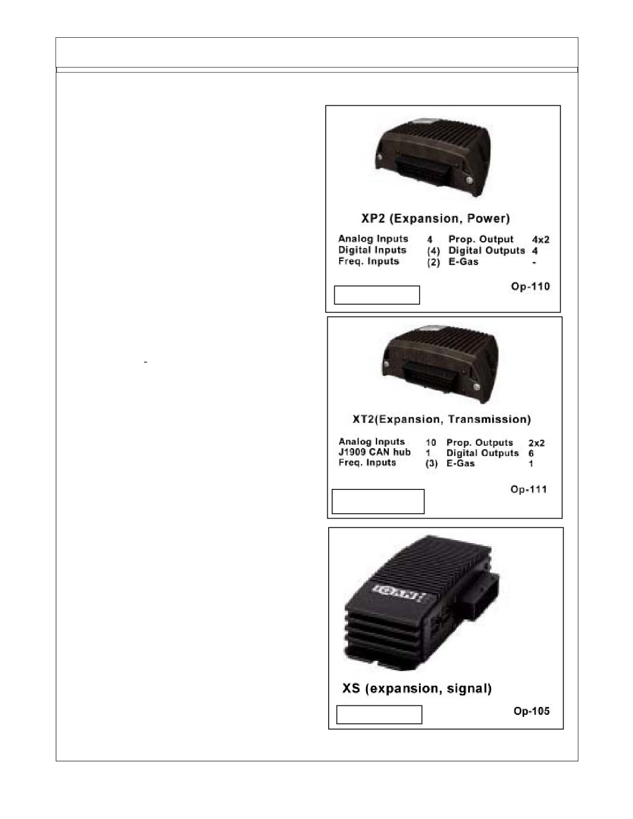
The XP2 The XP2 is a controller module
that is mounted at the front of the tractor next to the
maverick control valve. The function of this compo-
nent is to provide a gateway for incoming and outgo-
ing information. Information is sent via the network to
this module in order to provide control of the sole-
noids for valve operation (See Figure 9) REFER-
ENCE PRODUCT MANUAL FOR MDM DISPLAY.
THIS MANUAL IS AVAILABLE FROM THE MANU-
FACTURER ON THE INTERNET
AT
www.iqan.com viewable and printable with
FIGURE 9
ADOBE ACROBAT READER. If you do not have
Adobe Acrobat Reader it can be obtained at
The XT2. The XT2 is also a controller mod-
ule that is mounted at the front of the tractor on the
side of the tank, The function of this component is to
provide a gateway for incoming and outgoing infor-
mation. This module receives input from instrumen-
tation, then provides that information to the network
for further utilization.
(See Figure 10) REFER-
ENCE PRODUCT MANUAL FOR MDM DISPLAY.
THIS MANUAL IS AVAILABLE FROM THE MANU-
FACTURER ON THE INTERNET
AT
www.iqan.com viewable and printable with
FIGURE 10
ADOBE ACROBAT READER. If you do not have
Adobe Acrobat Reader it can be obtained at
The XS The XS is expansion module that
provides extra input and output capabilities in order
to gain more flexibility on the network (See Figure
11). The XS is responsible for receiving the signals
from the joystick and other in cab inputs and making
them available on the network. REFERENCE
PRODUCT MANUAL FOR MDM DISPLAY. THIS
MANUAL IS AVAILABLE FROM THE MANUFAC-
TURER ON THE INTERNET AT www.iqan.com
viewable and printable with ADOBE ACROBAT
READER. If you do not have Adobe Acrobat
Reader it can be obtained at www.adobe.com.
FIGURE 11
New Holland (NH TS-100A, 115A, 125A, 135A Asy. Man) 01/05
Section 10 - 7
CONTROL VALVE - INSTRUMENTATION
Maverick Instrumentation:
Instrumentation The Maverick Boom uti-
lizes instrumentation for certain decision making
activities. Listed below are the sensors included on
this unit. Tank Temperature Sensor, Charge Pres-
sure Filter Switch, Valve Pressure Filter Switch and
Return Filter Switch.
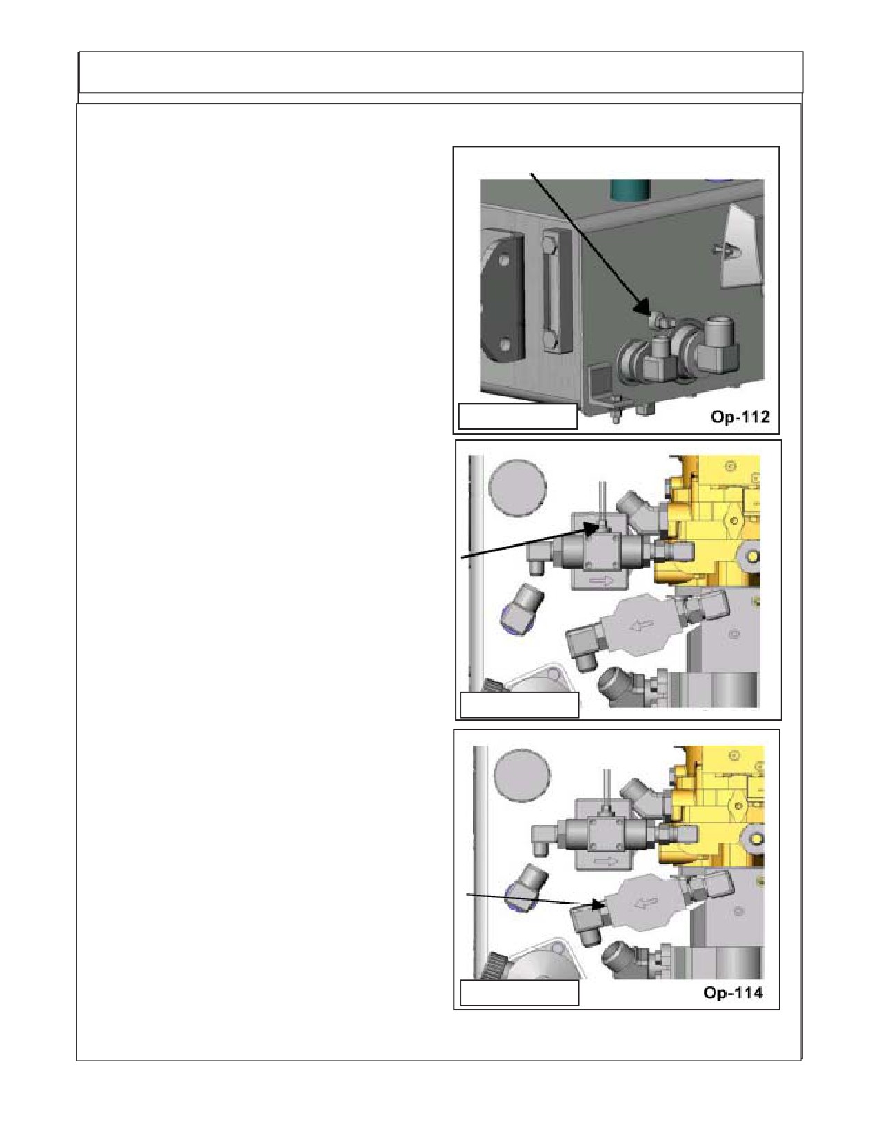
Tank Temperature Sensor. The tank tem-
perature sensor monitors the fluid temperature in
the area of the pump suction screens. the tempera-
ture is real time and is used on the network to
accomplish certain objectives. The first, is to display
on the interface while the cutter circuit is operating.
FIGURE
12
The second, is to be used to control the electric fan
on the hydraulic cooler. At any time the fluid level
reaches 150° F. the fan is activated and remains
activated until fluid temperature drops to or below
the desired temperature (See Figure 12).
The Charge Pressure Filter Switch The
charge pressure filter switch is located at the filter in
the charge loop on the hydrostatic pump (See Figure
13). The sensor monitors the back pressure created
by the filter element when in use. When the back
pressure reaches a setting of 50 psi the switch will
trigger and prompt the operator for a filter element
change of filter element.
FIGURE
13
The Valve Pressure Filter Switch The
Valve pressure filter switch is located at the pres-
sure filter in the valve pressure circuit, between the
closed center load sense pump and the control
valve (See Figure 14). The sensor monitors the back
pressure created by the filter element when in use.
When the back pressure reaches a setting of 50 psi
the switch will trigger and prompt the operator for a
filter element change.
WARNING! This filter does not have a by-
pass. The element must be changed at the
appropriate time to avoid element danmage and
system contamination.
FIGURE 14
New Holland (NH TS-100A, 115A, 125A, 135A Asy. Man) 01/05
Section 10 - 8
CONTROL VALVE - INSTRUMENTATION
Maverick Instrumentation:
(continued)
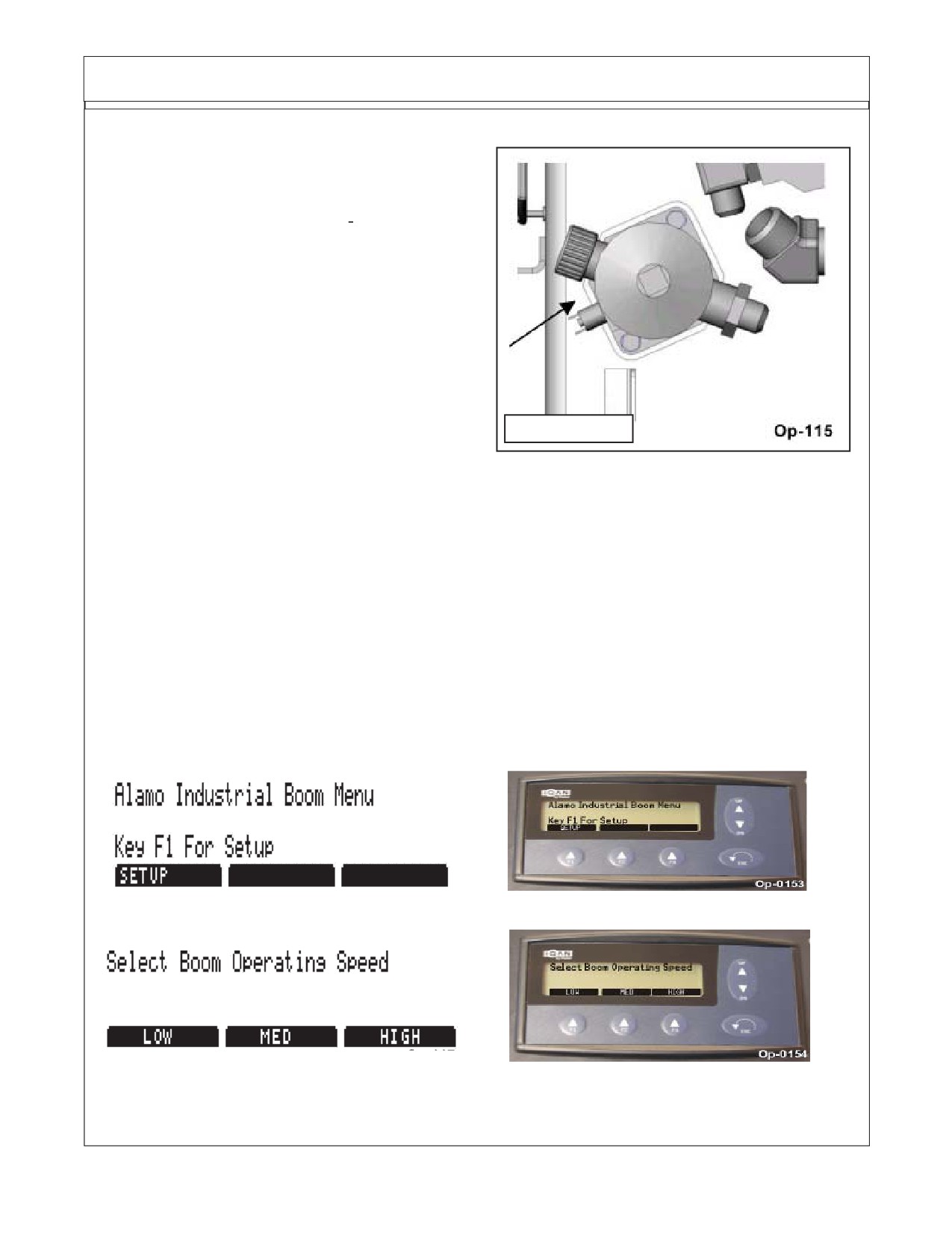
The Return Filter Switch. The return filter
switch is located at the return filter mounted on to the
tank top. The fluid returning from the cylinder control
valve is filtered before returning to tank at this loca-
tion (See Figure 15). The sensor monitors back
pressure created by the filter assembly while cylin-
der circuit is in operation. When the back pressure
reaches 25 psi the switch will trigger and prompt the
operator for a filter element change.
WARNING! This filter does not have a by-
pass. The element must be changed at the
FIGURE 15
appropriate time to avoid element damage and
system contamination.
Maverick Operator Interface :
The Operator Interface The operator selects parameters provided by a menu system in the
MDM display control box. The parameters are used to establish how the boom unit functions. The menu
system is comprised of two sections. The first section is setup, the second section powers up the boom
control circuit and cutter head circuit. The following steps outline how to successfully page through the
menu system to execute operation. See the end of this section for Joystick control operation after start
up procedure is completed.
Executing Set-Up The following representations will outline the steps necessary to execute
set-up.
* Key Escape or back at anytime to revert to the previous screen or restart the set-up menu at any time.
* Key F-1 to access the set-up menu.
* Key the corresponding F-key to establish the desired boom speed. This parameter is
provided for customizable operation.
New Holland (NH TS-100A, 115A, 125A, 135A Asy. Man) 01/05
Section 10 - 9
CONTROL VALVE - INSTRUMENTATION
Maverick Operator Interface : (continued)
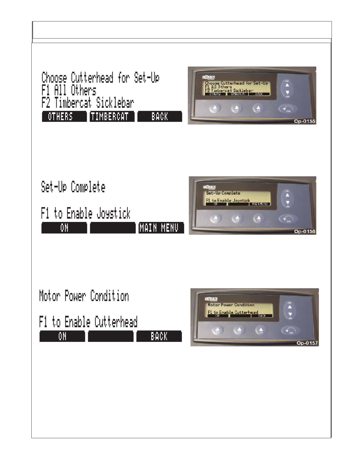
* Key the corresponding F-key for the head attachment that will be used, This is an important step
because this parameter chooses which direction the fluid will enter the motor. The Timbercat Sicklebar
mower is the only head attachment that currently requires the operator to send reverse flow, for all
others chose F-1 key for standard directional flow.
* Key F-1 to activate Joystick, the Boom will not move until the joystick is activated. The Boom function
Set-up is now complete, the boom speed, the head attachment has been chosen and the joystick has
been activated.
* Key F-1 to power motor. This is best done when the engine RPM is at idle speed. Doing this a t high
RPM will cause the system pressure to surge sending fluid over the relief and causing excess heat to
be introduced into the system.
* At any time the Cutter Head Motor E-Stop (emergency stop) can be pushed to disable the motor
circuit. If this is done the Switch must be raised in the run position before the motor circuit can be
reactivated.
New Holland (NH TS-100A, 115A, 125A, 135A Asy. Man) 01/05
Section 10 - 10
CONTROL VALVE - INSTRUMENTATION
Maverick Operator Interface : (continued)
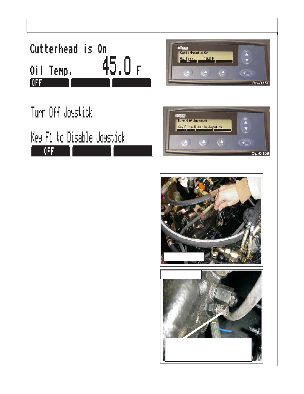
* At this time the motor circuit is powered and the mower head motor is active. This screen also shows
the tank temperature in degrees Fahrenheit. To turn off the motor at this time Key F-1.
* The Joystick Master control switch must be off to prevent accidental movement of boom and cutting
head when ever mower is not being operated, such as when in transport.
Cylinder Supply Pump Pressure
Adjust (If Needed):
Special Note: If after setting the display
controls, check to make certain that functions
operate correctly. If the Boom will not lift. The Pump
for the Cylinder supply may have to be adjusted.
Pressure Adjust
This is a simple process that will require a 7/16"
Control (7/16" Hex)
wrench for this adjustment and a 1/2" wrench for the
locking nut. Looking on the LH side of the pump
there are two adjustments, one has a 7/16" hex
FIGURE 16
head and the other a ridged round head, Only adjust
the one with the hex head. DO NOT adjust or
change the round ridged adjustment as it is set from
FIGURE 17
the factory. Adjust the 7/16" hex one by turning it in
till it seats completely (Do not force adjustment after
is seats). Then back it back out 1/2 turn, this will give
you the 2800 psi required to operate the boom. (See
Figure 16 & 17). Hold the adjusting nut while turning
the locking nut so the adjustment nut does not turn
with it changing the setting.
Pressure Adjust Nut
(7/16" Hex)
&
Locking Nut (1/2" Hex)
New Holland (NH TS-100A, 115A, 125A, 135A Asy. Man) 01/05
Section 10 - 11
CONTROL VALVE - JOYSTICK
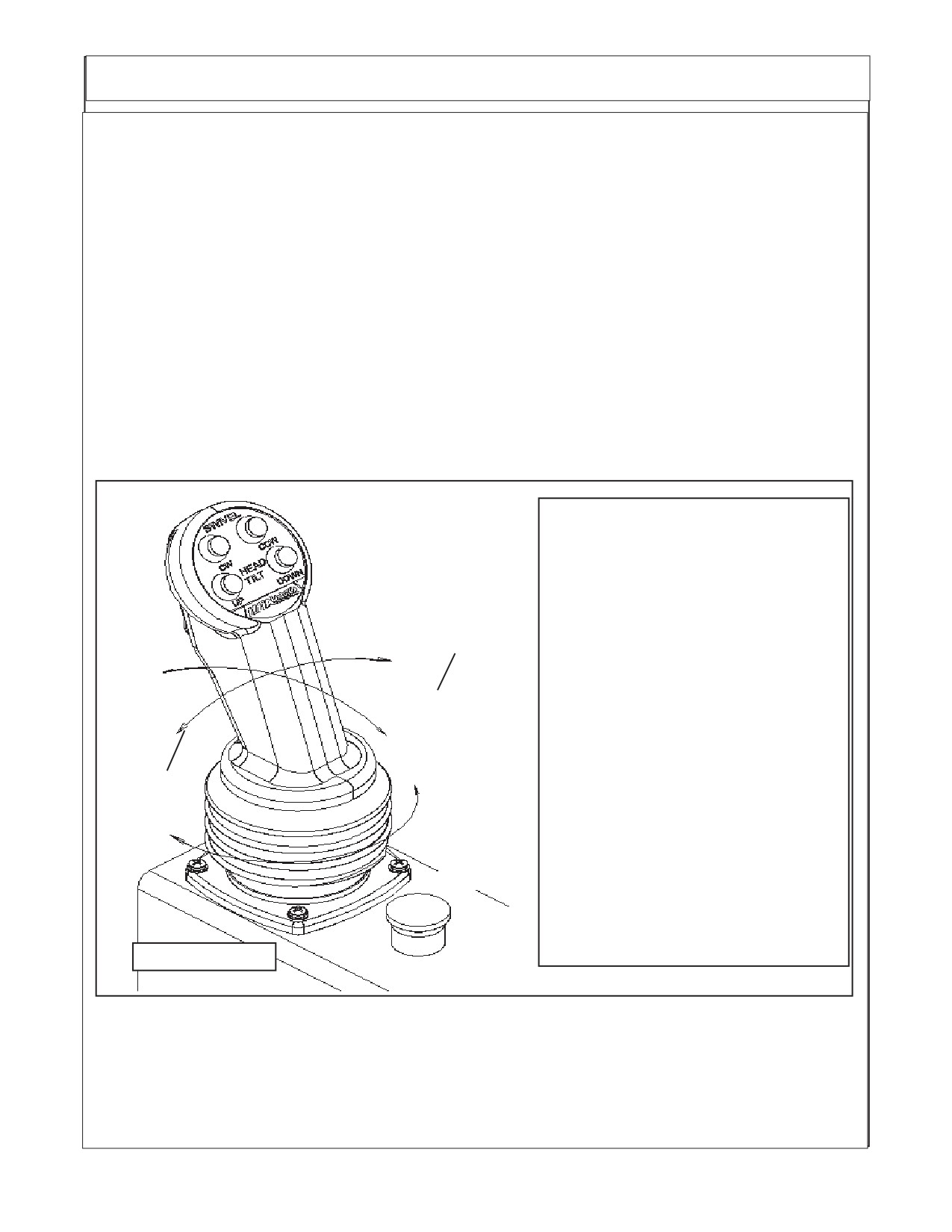
JOYSTICK FUNCTIONS: (Figure 18)
To operate a function the following series of events must work.
1. The Joystick Controller is moved in the correct direction the required distance, During its movement
an electrical signal is sent to the electric Controller in the proper Valve Section of the Control Valve.
2. The Electric Controller sends an electrical signal, which causes the Proportional Control Valves to
actuate the proper amount based on the signal from the Controller. EXAMPLE: Valves 1 & 3 allow
Pilot Pressure Oil to flow to the corresponding end of the Spool, Thus causing it to move. Valves 2
& 4 allow the Oil from the opposite end of the Spool to return to the Tank. (NOTE: Lift, Swing and
Dipper functions are Proportional, Door and Tilt functions are “ON” or “Off” Only, See later section
for explanation of Proportional).
3. The Spool position Transducer sends an electrical signal to the Electronic Controller which indicates
the position of the Spool.
4. The Electronic Controller will continue to adjust the Valves (1 - 4) in order to maintain an equilibrium
between the Joystick signal and the feedback signal.
5. Reaction time from the time the Joystick is moved until the Spool moves is approximately 300
milliseconds.
Trigger + Dipper = Telescope
Joystick Functions
Trigger + Swivel = Door
Push Buttons Only
Top Left
= Swivel CW
Top Right
= Swivel CCW
Trigger
Bottom Left
= Tilt Up
Botom Right
= Tilt Down
Dipper Tele
Lift
Up Out
Push Button & Trigger Switch
Down
Top Left
= Door Open
Lift
Top Right
= Door Close
Dipper Tele
Up
Handle Movement
Down In
Swing
Push Front
= Lift Down
Out
Pull Back
= Lift Up
Swing
Push Right
= Dipper Up
In
Push Left
= Dipper Down
Rotate Right
= Swing Back
Rotate Left
= Swing Forward
Run
Trigger & Handle Movement
E-Stop
Push Right
= Telescope Out
Push Left
= Telescope In
FIGURE
18
Stop
The Joystick is P/N 02981374. The Plug in connections are marked with numbers on the plastic plug.
The wires are solid color or a color with a stripe. The Plugs should not fit but one way and that is by
matching the codes on the plugs.
New Holland (NH TS-100A, 115A, 125A, 135A Asy. Man) 01/05
Section 10 - 12
Install Front Pump & Tank Cover
Install Front Pump & Tank Cover:
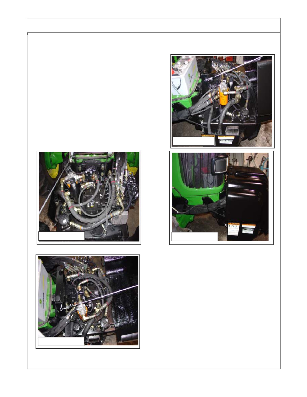
1.
Install The Front Pump / Tank Cover. The front
cover and tank cover are a bolt on part. The hinges are
made onto the cover and the other half of the hinges are
made on the tank mount bracket. There are two bolts (one
each hinge) that bolt the two hinge halves together. The
is a safety cable that will bolt to the cover and the tank
mount bracket, this is to prevent the cover from opening
to far forward and hitting the ground.
There are retaining latches that will bolt to the tank
mount bracket and the cover. The holes for the fasteners
will have to drilled by the installation technician in the tank
mount brackets and the front cover. (See Figure 19, 20,
21 & 22)
FIGURE 19
FIGURE 20
FIGURE 21
FIGURE 22
New Holland (NH TS-100A, 115A, 125A, 135A Asy. Man) 01/05
Section 10 - 13
Adjust Boom Swing Stop
CAUTION !
You MUST READ and UNDERSTAND this
section as it is critcal BEFORE attempting to put boom rest position
the first time. FAILURE TO PERFORM THIS ADJUSTMENT could cause
damage to the cab of the tractor.
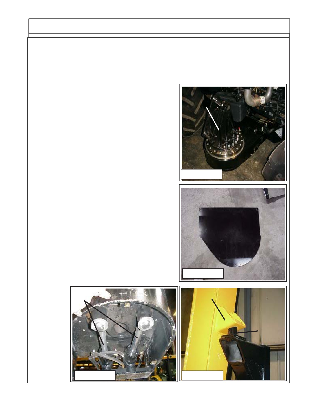
Boom Swing Adjustment:
Turret
1.
Boom Swing Stop Location. The boom Stop adjust-
ment cannot be seen from the top of the turret assembly (See
Assembly
Figure 23). If the bottom cover plate (See Item 24) is not
already removed it will need to be, it is bolted on from the
under side of the turret assembly. From the under side you
will see the swing cylinders and cylinder pivot mounts (See
Figure 25).
2.
The Swing Stop Lug which is part of the Turret
Cylinder Link Weldment (See Figure 27). On the side toward
the rear there will be a lug with a bolt and locking nut in it (See
Figure 27). Loosen the bolt and locking nut, turn the bolt
Figure 23
outward.
3.
Swinging Boom, DO NOT Swing Boom until the
boom has been run with it sticking out away from tractor and
all electronic control adjustments have been done. The
boom must be working smoothly. Slowly (with low engine
RPM) with some one guiding you swing boom inward toward
Bottom
cab until the boom rest lug is aligned with the boom rest pin
Turret
(See Figure 26). Set boom securely down over pin.
Cover
4.
Final Swing Stop Adjustment. Unscrew the stop bolt
(See Figure 27) until the head is against the swing stop lug of
the turret cylinder link weldment (See Figure 27). Hold the
bolt so it won't turn tighten the locking nut down against the
turret stop swing lug. Recheck to make certain the boom will
Figure 24
not hit the cab of the tractor. It will stop at the turret stop lug
when properly
Swing
adjusted. This
Boom
Cylinders
may have to be
Rest
adjusted more
Lug
Boom
than once,
Rest
NEVER allow
Pin
unit to be run if
Boom will hit
the cab, this will
damage cab.
Figure 25
Figure 26
New Holland (NH TS-100A, 115A, 125A, 135A Asy. Man) 01/05
Section 10 - 14
Adjust Boom Swing Stop
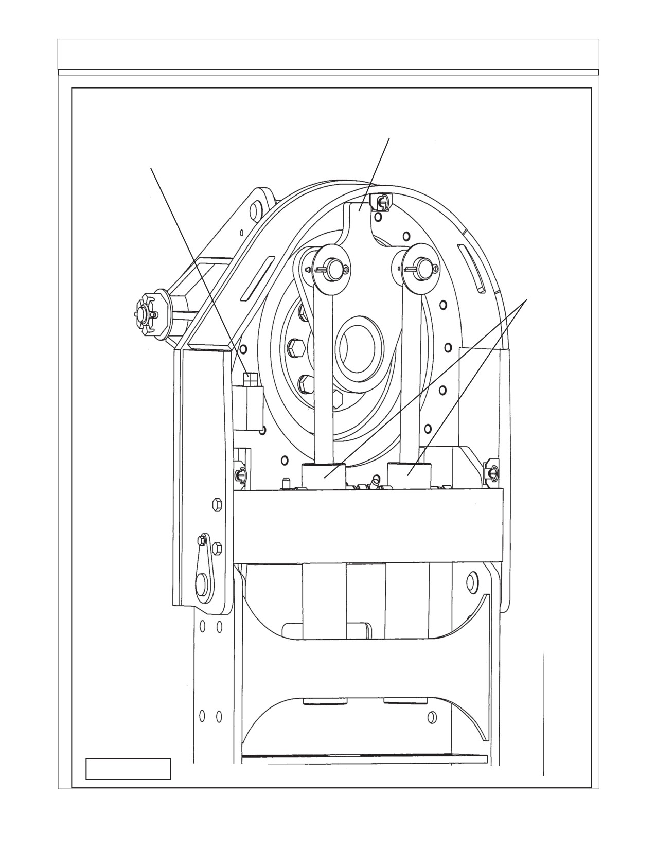
Turret Assembly as seen from the bottom
Swing Stop Lug
Turret Swing Stop Lug with
Built onto the
Adjusting Bolt & Locking Nut
Turret Cylinder
Link Weldment
Swing
Cylinders
Figure 27
New Holland (NH TS-100A, 115A, 125A, 135A Asy. Man) 01/05
Section 10 - 15
NOTES
New Holland (NH TS-100A, 115A, 125A, 135A Asy. Man) 01/05
Section 10 - 16
Section 11
Maverick
New Holland Tractor
TS-100A, 115A, 125A, 135A
Mounting Specifications
Maverick (NH TS-100A,115A, 125A, 135A Asy. Man) 01/05
11 - 1
Mounting Specifications
New Holland TS-100A / 115A / 125A / 135A Cab/2&4wd
As of 01-05-05
10.00-16SL (F-2) Min / 11.00-16SL (F-2M) Max 2wd Front Tire
12.4-24 (R-1) Min / 14.9-24 (R-1W) Max 4wd Front Tire
18.4-30 (R-1) Min / 18.4-34 (R-1W) Max Rear Tire
Mount Kits:
24' Maverick 2wd* Mount Kit ………………
02982343 (Page 11-7 thru 11-10)
24' Maverick 4wd Mount Kit …………………
02982341 (Page 11-11 thru 11-14)
30' Maverick 4wd** Mount Kit ……………...…... 02981892 (Page 11-15 thru 11-18)
Common pParts Box:
Common Parts Box
……………..……..02981781 (Page 11-4 thru 11-6)
(Common Parts Box shipped with all models no matter which boom or tractor model)
* 2wd tractors must be equipped with heavy duty, eight bolt front wheel hubs & spindles
** 30' Maverick booms must be mounted on 4wd tractors only due to front axle spindle
loading.
Options:
Extra Maverick Installation Manual …………..…… 02982279
Standard Features:
1. Modified exhaust pipe for boom transport clearance.
2. Replacement arm rest with joystick console.
3. Neapco style driveline with double U-joints.
4.
1400# wheel weight plus 408# auxiliary weight kit.
5. Right hand replacement Lexan door 3/8" Lexan replacement door (right side only). (See Figure 4)
6.
51 gallon replacement fuel tank.
7.
~10" of ground clearance with the min. tire size shown.
Restriction Notes:
1. Exhaust must be modified for clearance. (See Figure 1)
2. Battery box must be relocated by installing battery relocation brackets . (See Figure 3)
3. Factory Seat Arm rest (RH Side) will be replaced by metal arm rest joystick mount. (See Figure 2)
4. Electronic components and display modules will have to be mounted in cab. (See Figure 5), these
must be mounted inside Cab to keep them protected from weather.
5. Display must be set to correct operating parameters before unit will function (See Figure 6).
Maverick (NH TS-100A,115A, 125A, 135A Asy. Man) 01/05
11 - 2
Mounting Specifications
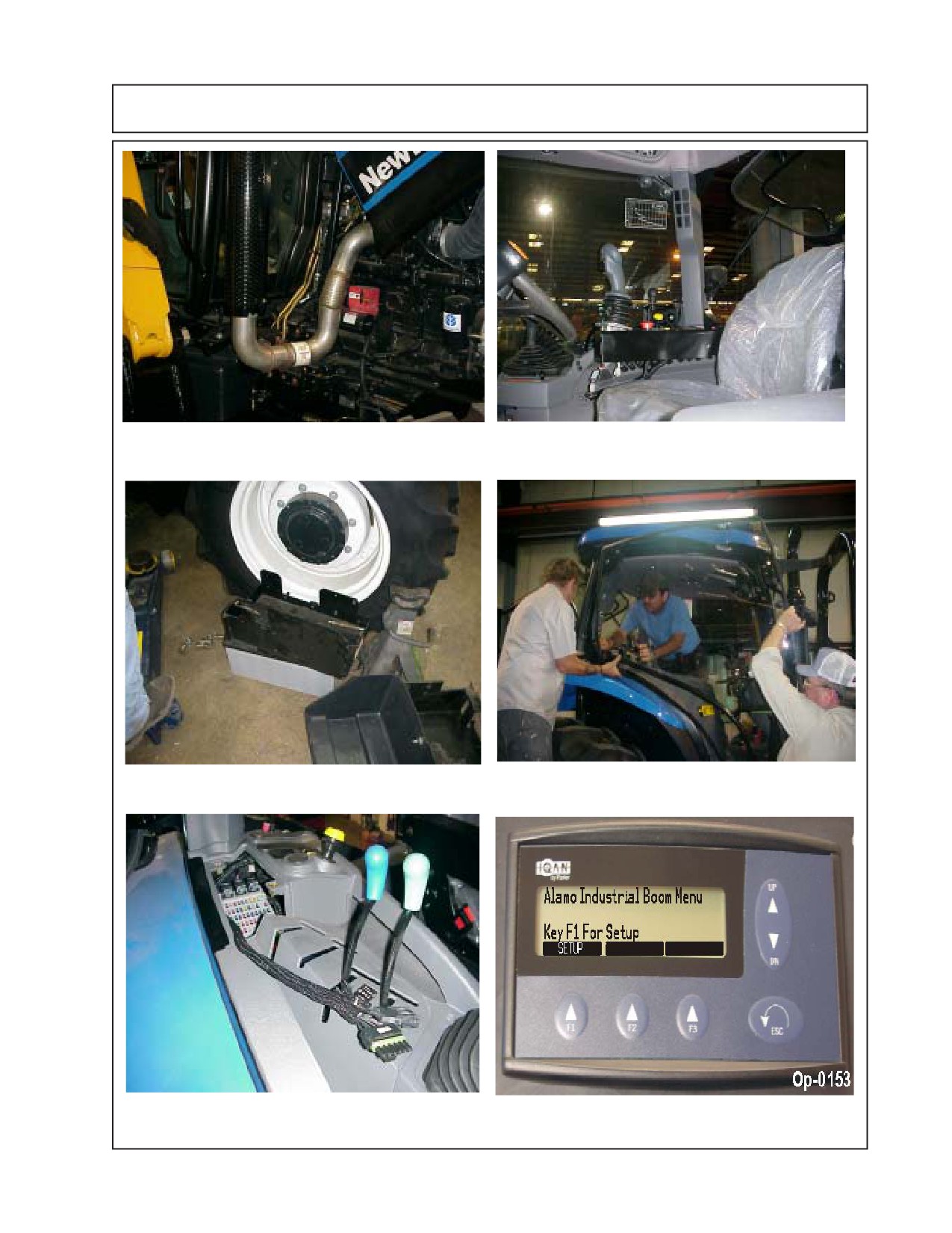
Figure 1: Replacement Exhaust Pipe
Figure 2: Seat-Mounted Joystick
(Elbow) & Bracket
Figure 4: Lexan Door Replacement Kit
Figure 3: Battery Box Clearance
Figure 5: Electronic Module mounted &
Figure 6: Electronic Display Screen
unseen behind cab panel
mounted in Cab in Operator view.
Maverick (NH TS-100A,115A, 125A, 135A Asy. Man) 01/05
11 - 3
Common Box - Component List
IMPORTANT NOTICE; These are parts that are shipped with every unit, these parts will remain
the same no matter which size boom is used or which model tractor is used. DO NOT order any of these
parts unless you are certain that that is what you want, most theses a are complete assemblies and may
contain more prts than are wanted to perform repairs. If ordering parts that are listed here it is recommended
that you look the parts in a regular parts manual under the specific assembly number.
02981781 Common box Consist of the Following Items:
ITEM
PART NO.
QTY.
DESCRITION
1.
00037200
7
LOCKNUT, TOPLOCK 3/4”-NC
2.
02981381
1
PUMP COVER ASSEMBLY
3.
02959924
12
LOCKNUT, TOPLOCK 1/4”-NC PLB
4.
10058000
10
BOLT, HEX HEAD 1/4”-NC X 1” PL GR5
5.
02981441
2
KNOB, CR30 X 1-1/2” STUD
6.
00024100
6
FLATWASHER, 1/4” PL STD
7.
00992000
3.3
CABLE, 1/4” AIRCRAFT (7X19)
8.
00001000
2
CABLE CLAMP
9.
02981377
1
OIL COOLER ASY W/ FAN
10.
00015800
8
LOCKNUT, TOPLOCK 3/8”-NC
11.
00011100
12
FLATWASHER, 3/8” STD
12.
02981383
1
COOLER MOUNT, RH
13.
02981384
1
COOLER MOUNT, LH
14.
02090800
2
ADAPTER, HYD ELBOW 12MB - 12MJ90°
15.
02962181
6
ADAPTER, HYD STRAIGHT
16.
02977622
1
DIVERTER SOLENOID VALVE
17.
02981803
1
VALVE AND HYD TANK ASY (Includes the Next 47 Items)
02981373
1
INDICATOR, ELEC W/PACKARD
02981704
1
MOUNT, MODULE
03200762
1
ADAPTER, HYD ELBOW 6MB - 4MJ 90°
02962181
2
ADAPTER, HYD, STRAIGHT
00015800
7
LOCKNUT, TOPLOCK
3/8”
00011100
5
FLATWASHER , 3/8” STD
00753642
7
BOLT, HEX HEAD 3/8” -NC X 1-1/4” PL GR5
02964135
1
ADAPTER, HYD STRAIGHT
02090800
4
ADAPTER, HYD ELBOW 12MB-12MJ90°
02981371
1
FILTER, MEDIUM PRESSURE
00001800
4
LOCKNUT, TOPLOCK 1/2”-NC PLB
02981436
1
KIT, FLANGE 20, CODE 61
02981463
1
ADAPTER, FLANGE 1-1/4” X 20MJ 45°
02981468
1
BRACKET, SHIPPING ONLY
00002700
2
FLATWASHER, 1/2” PL STD
00001300
4
LOCKWASHER, 1/2”
02892000
6
BOLT, HEX HEAD 1/2"-13 NC X 1-1/2" PL GR8
02968923
1
FILTER ASY, PRES ELEMENT
63042700
1
ADAPTER, HYD, STRAIGHT
03200587
1
PLUG, HEX HEAD #8MB
02981372
1
FILTER, HEAD W/IND PORT
02822700
1
ADAPTER, HYD ELBOW
Continued Next Page
Maverick (NH TS-100A,115A, 125A, 135A Asy. Man) 01/05
11 - 4
Common Box - Component List
02981781 Common box Consist of the Following Items:
(Contiuned from previous page)
ITEM
PART NO.
QTY.
DESCRITION
02968167
1
ADAPTER, HYD STRAIGHT 16MB - 8MJ
02981435
1
ADAPTER, HYD 10MB - 10 FJX90 ST
02043600
2
ADAPTER, HYD ELBOW 16MB -16MJ45°
02981369
1
PUMP, LS VARIABLE DISP
02978986
1
PUMP, MED DUTY HYDROSTAT
02981388
1
TANK ASY, HYDRAULIC
02981427
1
HOSE, # 8 - 8FJX - 8FJX90 - 24” LG
02981428
1
HOSE, # 8 - 8FJX - 8FJX90° - 21” LG
02981429
1
HOSE, # 12 - 12FJX - 12FJX - 23” LG
02981430
1
HOSE, # 12 - 12FJX - 12FJX - 31” LG
02981431
1
HOSE, # 4 - 4FJX - 4FJX90 - 35” LG
02981432
1
HOSE, # 4 - 4FJX - 4FJX90 - 20” LG
02981433
1
HOSE, # 20 - 20FJX - 20FJX - 24” LG
02981462
1
HOSE, # 12 - 12FJX - 12FJX90 - 20” LG.
02981986
1
DECAL, HOSE & ELEC CONNECTION
02979473
1
DECAL, AW ISO VG 100
02971123
1
DECAL, WARNING PRESSURIZED TANK
02965262
1
DECAL, WARNING HOSE BURST
02971943
1
DECAL, ALAMO IND YELLOW
02981888
1
ASY, VALVE & FITTINGS
02968896
1
PLASTIC TIE, ORANGE 11LG
02968894
1
PLASTIC TIE, RED 11LG
02971943
1
DECAL, ALAMO IND YELLOW
02982347
1
ADAPTER, HYD 16MB - 10MJ STRAIGHT
02972064
1
ADAPTER, HYD ELBOW 16MB - 8MJIC 90°
18.
02981805
1
ELECTRONIC KIT (includes the following 9 items)
02981374
1
CONTROLLER, 3/AXIS 5 BUTTON
02981375
1
HARNESS, WIRE, CONTROLS
02981376
1
HOUSING, DISPLAY & SWITCH
02981531
1
MODULE, XP2, EXPANSION
02981532
1
MODULE, XT2, EXPANSION
02981533
1
MODULE, XS, EXPANSION
02964028A
1
SWITCH, PUSH PULL
02982252
1
DWG, INST MAVERICK HARNESS
02982340
1
ASY, MDM MODULE & PROGRAM
19.
02981517
2
BOLT, EYE TURNED 1/4”-NC20 X 1”
20.
02976531
10
ADAPTER, HYD ELBOW 6FJX - 6FJX45°
21.
02981953
5
HOSE HANGER, FORMED
22.
02981787
1
BOLT, HEX HEAD 3/4”-NC X 1-1/2” PL GR8
23.
02981988
2
DECAL, JOYSTICK OPERATION
24.
02981992A
1
OPERATORS MANUAL & PARTS MANUAL ASSEMBLY
25.
02918600
6
BOLT, HEX HEAD 3/4”-10NC X 2” PL GR8
26.
00011400
4
BOLT, HEX HEAD 3/8”-NC X 1”
Continued Next Page
Maverick (NH TS-100A,115A, 125A, 135A Asy. Man) 01/05
11 - 5
Common Box - Component List
02981781 Common box Consist of the Following Items:
(Contiuned from previous page)
ITEM PART NO.
QTY. DESCRITION
26.
00011400
4
BOLT, HEX HEAD 3/8”-NC X 1”
27.
00023100
4
BOLT, HEX HEAD 3/8”-NC X 1-1/2” PL GR5
28.
00017000
2
LOCKWASHER, 1/4” PL STD
29.
00776031
1
CANISTER, F/ MANUALS
30.
00776481
1
DECAL SHEET, CANNISTER MANUAL
31.
02977417
1
DECAL, OPERATORS MANUAL INSIDE
32.
107079
1
WIRE, BLACK 14 GA. X 24” LONG
33.
02982339
2
OVAL SLEEVE, 5/32” DIA.
34.
D377
1
BOOKLET, DECAL BOOM MOWER
35.
02981822
1
HOSE BRACKET WELDMENT
36.
00019600
1
LOCKWASHER. 1/2” HEAVY PL
37.
02892000
1
BOLT, HEX HEAD 1/2”-13NC X 1-1/2” PL GR8
38.
02981992CA
1
MANUAL CANNISTER ASSEMBLY
Maverick (NH TS-100A,115A, 125A, 135A Asy. Man) 01/05
11 - 6
Mounting Component ID 24 ft. Cab & 2wd
New Holland
TS-100A / 115A / 125A / 135A
Cab & 2wd
IMPORTANT NOTICE: The following Part / Assembly Numbers are for reference and
should not be ordered as replacement parts, unless all the components in that assembly are
wanted. These will break down to bills of material of the components. Some of numbers listed are
NOT individual Parts but complete assemblies and/or box of assemblies. Check before ordering.
24 foot Maverick 2wd* Mount Kit
(* 2wd tractors must be equipped with heavy duty, eight bolt front wheel hubs & spindles)
02982343 Maverick Mount Kit - NH TS-100A/115A/125A/135A Cab 2 wd:
Consist of the Following Items
Item
Part No.
Qty
Description
1.
02980888
1
LEXAN REPLACEMENT DOOR KIT, RH SIDE
2.
02971789
1
WHEEL WEIGHT KIT, 1400 LBS.
3.
02976671
1
AUXILLARY WHEEL WEIGHT KIT 408LBS.
4.
02980938
1
REPLACEMENT FUEL TANK KIT
5.
02982005
1
RAIL WELDMENT, RH REAR
6.
02982006
1
RAIL WELDMENT, LH REAR
7.
02982014
1
RAIL WELDMENT, RH FRONT
8.
02982015
1
RAIL WELDMENT, LH FRONT
9.
02982314
1
BOOM REST WELDMENT
10.
02982344
1
COMPONENT BOX
02982344 Component Box: Consist of the following Item No.
Item
Part No.
Qty
Description
1
02980699
1
PULLEY ADAPTER NH TS-A
2
02980719
1
ASSY, TS-A PUMP MOUNT W/COVER
3
02980694
1
PLATE, BOOM REST STABILIZER
4
02980916
1
KIT, EXHAUST RELOCATION TS115A
5
02981750
1
KIT, BATTERY RELOCATION
6
02982000
1
DRIVELINE, MODIFIED 02975257A
7
02982157
1
HOSE BUNDLE 6 CYL MAVERICK
Continued next page
Maverick (NH TS-100A,115A, 125A, 135A Asy. Man) 01/05
11 - 7
Mounting Component ID 24 ft. Cab & 2wd
02982344 Component Box: Consist of the following Item No.
Continued from previous page
Item
Part No.
Qty
Description
8
02981404
1
MOUNT, TANK, RAIL, RH,TSA
9
02981405
1
MOUNT, TANK, RAIL, LH,TSA
10
02982022
1
WLDMT. BOOM REST STABILIZER
11
02981415
1
WELDMENT, ARMREST, CONTROLLER
12
02982279
1
INST MANUAL, NH TS-A MAVERICK
13
02981464
1
ASY, MOUNT PUMP COVER TSA
14
02982292
1
HOSE #12-12FJX-12FJX-24LG
15
02982324
1
PLATE, IQAN MOUNT
16
02982345
1
BOLT BAG, NH TS115A C/2 MV24
Component Box P/N 02982344 is in Mount Kit P/N 02982343
02982345 Bolt Bag: Consist of the following Item No.
Item
Part No.
Qty
Description
1
02980967
4
BOLT, HEX HEAD M12-P1.75 X 60mm PL GR10.9
2
00754566
4
LOCKWASHER, 12MM
3
02976344
4
BOLT, HEX HEAD 7/16”-NC X 1-1/4” PL GR8
4
00022200
4
LOCKWASHER, 7/16” PL
5
02975692
18
BOLT, HEX HEAD M20-P2.5 X 50MM PL GR10.9
6
02971158
18
LOCKWASHER, 20MM
7
00059500
4
NUT, HEX 1”-NC PL
8
02032200
4
LOCKWASHER STD,1”
9
02980723
8
BOLT, HEX HEAD M18-P1.5 X 80 PL GR10.9
10
02970066
8
LOCKWASHER, 18MM
11
02959587
2
BOLT, HEX HEAD, 3/4”-10NC X 6" PL GR8
12
00037200
26
LOCKNUT, 3/4”-NC
13
02960521
4
BOLT, HEX HEAD 3/4”-NC X 2-3/4” PL GR8
14
5312316
70
WASHER, 3/4" (20 MM) HARDENED
15
02963646
4
BOLT, HEX HEAD 3/4”-NC X 2-1/2” PL GR8
16
00748547
7
FLATWASHER, 1-1/32” X 2-3/16” X .22” HARDENED
17
02981985
8
WASHER,18MM HARDENED
18
02966556
3
BOLT, HEX HEAD 1"-NC X 11" PL GR8
19
02972088
8
BOLT, HEX HEAD 3/4”-NC X 3-1/2” PL GR8
20
02980721
1
BOLT, HEX HEAD 1"-8UNC X 10-1/2” PL GR8
21
02918600
8
BOLT, HEX HEAD 3/4”-10UNC X 2” PL GR8
22
00759457
4
BOLT, LAG 5/16” X 2” PL GR5
23
00011700
4
LOCKWASHER, 5/16 PL STD
24
00762398
2
BOLT, HEX HEAD M10-P1.5 X 30mm PL GR8.8
25
00755954
2
LOCKWASHER, M10 SPRING
Bolt Bag P/N 02982345 is in Component Box P/N 02982344 which is in
Mount Kit P/N 02982343
Maverick (NH TS-100A,115A, 125A, 135A Asy. Man) 01/05
11 - 8
Mounting Component ID
24 ft. Cab & 2wd
02971789 Wheel Weight Kit: Consist of the following Item No.
Item
Part No.
Qty
Description
1
02970758
1
WHEEL WEIGHT, 1400 LBS
2
02971569
3
WASHER, WHEEL WEIGHT
3
02971791
1
DRAWING, WHEEL WEIGHT INSTALLATION
4
02979603
3
BOLT, HEX HEAD 7/8”-NC X 16” PL GR 8 (4” OF THREAD)
5
00012200
3
LOCKWASHER, 7/8” PL STD
6
00012300
3
NUT, HEX 7/8”-NC
Wheel Weight Kit P/N 02971789 is in Mount Kit P/N 02982343
02976671 Auxillary Wheel Weight Kit: Consist of the following Item
No.
Item
Part No.
Qty
Description
1
00012200
2
LOCKWASHER, 7/8” PL STD
2
00012300
2
NUT, HEX 7/8”-NC
3
00760266
2
BOLT, HEAX HEAD 7/8”-NC X 5-1/2” GR8
4
02976644
3
PLATE, WHEEL WELDMENT
Auxilary Wheel Weight Kit P/N 02976671 is in Mount Kit P/N 02982343
02980938 Fuel Tank: Consist of the following Item No.
Item
Part No.
Qty
Description
1
00011100
3
FLAT WASHER, 7/8” PL STD
2
00015800
3
LOCKNUT, TOPLOCK 3/8”
3
00037200
2
LOCKNUT, 3/4”-NC
4
00001800
4
LOCKNUT, TOPLOCK 1/2”-NC PLB
5
02776600
4
BOLT, HEX HEAD 1/2”-13NC X 1-1/4" PL GR8
6
03200285
1
DECAL, WATCH YOUR STEP
7
00752405
2
BOLT, HEX HEAD 3/4”-NC X 5-1/2” PL GR8
8
108693
1
GAS CAP
9
02976633
1
WLDMT STEP
10
00753642
3
BOLT, HEX HEAD 3/8”-NC X 1-1/4” PL GR5
11
02980996
6
BOLT, SOCKET HEAD #10-24 X 1"
12
63121800
6
LOCKWASHER, #10 STD PL
13
31001000
6
FLATWASHER, 3/16” PL STD
14
02982198
1
WLDMT. FUEL TANK
15
02982206
1
WLDMT. FRONT BRACKET
16
02982207
1
WLDMT. REAR BRACKET
Replacement Fuel Tank Kit P/N 02980938 is in Mount Kit
P/N 02982343
Maverick (NH TS-100A,115A, 125A, 135A Asy. Man) 01/05
11 - 9
Mounting Component ID 24 ft. Cab & 2wd
02980888 Lexan Door kit, RH Door : Consist of the following Item No.
Item
Part No.
Qty
Description
1
02980803
1
LEXAN DOOR, NEW HOLLAND TS-A
2
02980889
1
TRIM PUSH ON WEATHER SEAL 199"
3
00021900
2
BOLT, HEX HEAD 5/16”-NC X 1-3/4” PL GR5
4
00750940
4
LOCKNUT , TOPLOCK 5/16”-NC PLB
5
02766400
2
BOLT, HEX HEAD 5/16”-NC X 1-1/2”
6
02981016
1
CARTON, NH TS-A LEXAN DOOR
7
02981035
1
INSERT,LEXAN DOOR INSTALLATION
Lexan Door Kit P/N 02980888 is in Mount Kit P/N 02982343
02980916 Exhaust Relocation Kit : Consist of the following Item No.
Item
Part No.
Qty
Description
1
02980917
1
PIPE, EXHAUST NH TS115A
2
02980728
3
BOLT, HEX HEAD M12-P1.75 X 30mm PL GR10.9
3
701513C
3
M12 FLATWASHER
4
00754566
3
LOCKWASHER, 12MM
5
02980933
1
WLDMT. EXHAUST BRACKET
6
02959132
2
CLAMP, 3 1/2HD MUFFLER CLAMP
Exhaust Reloctaion Kit P/N 02980916 is in Component Box P/N 02982344
which is in Mount Kit P/N 02982343
02981750 Battery Relocation Kit : Consist of the following Item No.
Item
Part No.
Qty
Description
1
02980917
1
PIPE, EXHAUST NH TS115A
1
02981725
1
WLDMT BATTERY BRACKET
2
00011400
3
BOLT, HEX HEAD 3/8”-NC X 1”
3
00012101
3
LOCKWASHER, 3/8” PL
4
00013901
3
NUT, HEX 3/8”-NC PL
Battery Reloctaion Kit P/N 02981750 is in Component Box P/N 02982344
which is in Mount Kit P/N 02982343
Maverick (NH TS-100A,115A, 125A, 135A Asy. Man) 01/05
11 - 10
Mounting Component ID 24 ft. Cab & 4wd
New Holland
TS-100A / 115A /125A / 135A
Cab & 4wd
Page 1-8 thru 1-11
24 foot Maverick 4wd
Mount KiT Only
Mount Kit P/N 02982341
Maverick (NH TS-100A,115A, 125A, 135A Asy. Man) 01/05
11 - 11