New Holland. Cab 2 WD / 4 WD TS-100A, TS-115A, TS-125A, TS-135A. ASSEMBLY MANUAL - page 4
Mounting Component ID 24 ft. Cab & 4wd
New Holland TS-100A/115A/125A/135A Cab 4wd
IMPORTANT NOTICE: The following Part / Assembly Numbers are for reference and
should not be ordered as replacement parts, unless all the components in that assembly are
wanted. These will break down to bills of material of the components. Some of numbers listed are
NOT individual Parts but complete assemblies and/or box of assemblies. Check before ordering.
24 foot Maverick 4wd Mount Kit
02982341 Maverick Mount Kit - NH TS-100A/115A/125A/135A Cab 4wd:
Consist of the Following Items
Item
Part No.
Qty
Description
1.
02980888
1
LEXAN REPLACEMENT DOOR KIT, RH SIDE
2.
02971789
1
WHEEL WEIGHT KIT, 1400 LBS.
3.
02980938
1
REPLACEMENT FUEL TANK KIT
4.
02982005
1
RAIL WELDMENT, RH REAR
5.
02982006
1
RAIL WELDMENT, LH REAR
6.
02982014
1
RAIL WELDMENT, RH FRONT
7.
02982015
1
RAIL WELDMENT, LH FRONT
8.
02982314
1
BOOM REST WELDMENT
9.
02981893
1
COMPONENT BOX
02981893 Component Box: Consist of the following Item No.
Item
Part No.
Qty
Description
1
02980699
1
PULLEY ADAPTER NH TS-A
2
02980719
1
ASSY, TS-A PUMP MOUNT W/COVER
3
02980694
1
PLATE, BOOM REST STABILIZER
4
02980916
1
KIT, EXHAUST RELOCATION TS115A
5
02981750
1
KIT, BATTERY RELOCATION
6
02982000
1
DRIVELINE, MODIFIED 02975257A
7
02982157
1
HOSE BUNDLE 6 CYL MAVERICK
8
02981404
1
MOUNT, TANK, RAIL, RH,TSA
9
02981405
1
MOUNT, TANK, RAIL, LH,TSA
10
02982022
1
WLDMT. BOOM REST STABILIZER
11
02981415
1
WELDMENT, ARMREST, CONTROLLER
12
02982279
1
INST MANUAL, NH TS-A MAVERICK
13
02981464
1
ASY, MOUNT PUMP COVER TSA
14
02982292
1
HOSE #12-12FJX-12FJX-24LG
15
02982324
1
PLATE, IQAN MOUNT
16
02981894
1
BOLT BAG, NH TS115A C/4MV
17
02981895
1
TS-A FRONT AXLE STABILIZER KIT
18
02982279
1
INSTALLATION MANUAL TS115A/125A/135A MAVERICK
Component Box P/N 02981893 is in Mount Kit P/N 02982341
11 - 12
Mounting Component ID 24 ft. Cab & 4wd
02981894 Bolt Bag: Consist of the following Item No.
Item
Part No.
Qty
Description
1
02980967
4
BOLT, HEX HEAD M12-P1.75 X 60mm PL GR10.9
2
00754566
4
LOCKWASHER, 12MM
3
02976344
4
BOLT, HEX HEAD 7/16”-NC X 1-1/4” PL GR8
4
00022200
4
LOCKWASHER, 7/16” PL
5
02975692
14
BOLT, HEX HEAD M20-P2.5 X 50MM PL GR10.9
6
02971158
14
LOCKWASHER, 20MM
7
00059500
4
NUT, HEX 1”-NC PL
8
02032200
4
LOCKWASHER STD,1”
9
02980723
8
BOLT, HEX HEAD M18-P1.5 X 80 PL GR10.9
10
02970066
8
LOCKWASHER, 18MM
11
02959587
2
BOLT, HEX HEAD, 3/4”-10NC X 6" PL GR8
12
00037200
26
LOCKNUT, 3/4”-NC
13
02960521
4
BOLT, HEX HEAD 3/4”-NC X 2-3/4” PL GR8
14
5312316
70
WASHER, 3/4" (20 MM) HARDENED
15
02963646
4
BOLT, HEX HEAD 3/4”-NC X 2-1/2” PL GR8
16
00748547
7
FLATWASHER, 1-1/32” X 2-3/16” X .22” HARDENED
17
02981985
8
WASHER,18MM HARDENED
18
02966556
3
BOLT, HEX HEAD 1"-NC X 11" PL GR8
19
02972088
8
BOLT, HEX HEAD 3/4”-NC X 3-1/2” PL GR8
20
02980721
1
BOLT, HEX HEAD 1"-8UNC X 10-1/2” PL GR8
21
02918600
8
BOLT, HEX HEAD 3/4”-10UNC X 2” PL GR8
22
00759457
4
BOLT, LAG 5/16” X 2” PL GR5
23
00011700
4
LOCKWASHER, 5/16 PL STD
24
00762398
2
BOLT, HEX HEAD M10-P1.5 X 30mm PL GR8.8
25
00755954
2
LOCKWASHER, M10 SPRING
Bolt Bag P/N 02981894 is in Component Box P/N 02981893 which is in
Mount Kit P/N 02982341
02971789 Wheel Weight Kit: Consist of the following Item No.
Item
Part No.
Qty
Description
1
02970758
1
WHEEL WEIGHT, 1400 LBS
2
02971569
3
WASHER, WHEEL WEIGHT
3
02971791
1
DRAWING, WHEEL WEIGHT INSTALLATION
4
02979603
3
BOLT, HEX HEAD 7/8”-NC X 16” PL GR 8 (4” OF THREAD)
5
00012200
3
LOCKWASHER, 7/8” PL STD
6
00012300
3
NUT, HEX 7/8”-NC
Wheel Weight Kit P/N 02971789 is in Mount Kit P/N 02982341
11 - 13
Mounting Component ID 24 ft. Cab & 4wd
02980938 Fuel Tank: Consist of the following Item No.
Item
Part No.
Qty
Description
1
00011100
3
FLAT WASHER, 7/8” PL STD
2
00015800
3
LOCKNUT, TOPLOCK 3/8”
3
00037200
2
LOCKNUT, 3/4”-NC
4
00001800
4
LOCKNUT, TOPLOCK 1/2”-NC PLB
5
02776600
4
BOLT, HEX HEAD 1/2”-13NC X 1-1/4" PL GR8
6
03200285
1
DECAL, WATCH YOUR STEP
7
00752405
2
BOLT, HEX HEAD 3/4”-NC X 5-1/2” PL GR8
8
108693
1
GAS CAP
9
02976633
1
WLDMT STEP
10
00753642
3
BOLT, HEX HEAD 3/8”-NC X 1-1/4” PL GR5
11
02980996
6
BOLT, SOCKET HEAD #10-24 X 1"
12
63121800
6
LOCKWASHER, #10 STD PL
13
31001000
6
FLATWASHER, 3/16” PL STD
14
02982198
1
WLDMT. FUEL TANK
15
02982206
1
WLDMT. FRONT BRACKET
16
02982207
1
WLDMT. REAR BRACKET
Replacement Fuel Tank Kit P/N 02980938 is in Mount Kit
P/N 02982341
02980888 Lexan Door kit, RH Door : Consist of the following Item No.
Item
Part No.
Qty
Description
1
02980803
1
LEXAN DOOR, NEW HOLLAND TS-A
2
02980889
1
TRIM PUSH ON WEATHER SEAL 199"
3
00021900
2
BOLT, HEX HEAD 5/16”-NC X 1-3/4” PL GR5
4
00750940
4
LOCKNUT , TOPLOCK 5/16”-NC PLB
5
02766400
2
BOLT, HEX HEAD 5/16”-NC X 1-1/2”
6
02981016
1
CARTON, NH TS-A LEXAN DOOR
7
02981035
1
INSERT,LEXAN DOOR INSTALLATION
Lexan Door Kit P/N 02980888 is in Mount Kit P/N 02982341
02980916 Exhaust Relocation Kit : Consist of the following Item No.
Item
Part No.
Qty
Description
1
02980917
1
PIPE, EXHAUST NH TS115A
2
02980728
3
BOLT, HEX HEAD M12-P1.75 X 30mm PL GR10.9
3
701513C
3
M12 FLATWASHER
4
00754566
3
LOCKWASHER, 12MM
5
02980933
1
WLDMT. EXHAUST BRACKET
6
02959132
2
CLAMP, 3 1/2HD MUFFLER CLAMP
Exhaust Reloctaion Kit P/N 02980916 is in Component Box P/N 02981893
which is in Mount Kit P/N 02982341
11 - 14
Mounting Component ID 24 ft. Cab & 4wd
02981750 Battery Relocation Kit : Consist of the following Item No.
Item
Part No.
Qty
Description
1
02981725
1
WLDMT BATTERY BRACKET
2
00011400
3
BOLT, HEX HEAD 3/8”-NC X 1”
3
00012101
3
LOCKWASHER, 3/8” PL
4
00013901
3
NUT, HEX 3/8”-NC PL
Battery Reloctaion Kit P/N 02981750 is in Component Box P/N 02981893
which is in Mount Kit P/N 02982341
02981895 TS-A Front Axle Stabilizer Kit : Consist of following Item No.
Item
Part No.
Qty
Description
1
02981316
1
CYLINDER, ASY
2
02981896
1
ADAPTER HYD, REDUCER 6FJX - 4MJ
3
02965166
1
ADAPTER HYD, TEE 6MJ - 6MJ - 6FJX
4
02960018
1
ADAPTER HYD, ELBOW
5
02960054
1
PLUG #4 MB W/T-VENT & O-RING
6
001845
1
HOSE #4 - 4FJX - 4FJX90 70LG
7
02983143
1
BRACKET WELDMENT, TOP
8
02983144
1
BRACKET WELDMENT, BOTTOM
9
02982320
1
CYLINDER SUPPORT WELDMENT
10
00752716
2
BOLT, HEX HEAD 1/2”-NC X 3-1/2” PL GR8
11
7B101128
2
BOLT, HEX HEAD 5/8”-NC X 3-1/2” PL GR8
12
00695100
2
LOCKNUT, TOPLOCK 5/8”
13
00001800
2
LOCKNUT, TOPLOCK 1/2”-NC PLB
14
02975669
4
BOLT, HEX HEAD M20-P2.5 X 60MM PL GR10.9
15
02971158
4
LOCKWASHER, 20MM
TS-A Front Axle Stabilizer Kit P/N 02981895 is in Component Box P/N
02981893 which is in Mount Kit P/N 02982341
11 - 15
Mounting Component ID
30 ft. Cab & 4wd
New Holland
TS-100A / 115A /125A / 135A
Cab & 4wd
Page 1-12 thru 1-15
30 foot Maverick 4wd**
Mount KiT Only
Mount Kit P/N 02981892
** 30' Maverick booms must be mounted on 4wd tractors
only due to front axle spindle loading.
11 - 16
Mounting Component ID
30 ft. Cab & 4wd
New Holland TS-100A/115A/125A/135A Cab & 4wd
IMPORTANT NOTICE: The following Part / Assembly Numbers are for reference and
should not be ordered as replacement parts, unless all the components in that assembly are
wanted. These will break down to bills of material of the components. Some of numbers listed are
NOT individual Parts but complete assemblies and/or box of assemblies. Check before ordering.
30 foot Maverick 4wd** Mount Kit
** 30' Maverick booms must be mounted on 4wd tractors only due to front axle spindle
loading.
02981892 Maverick Mount Kit - NH TS-100A/115A/125A/135A Cab 4wd:
Consist of the Following Items
Item
Part No.
Qty
Description
1.
02980888
1
LEXAN REPLACEMENT DOOR KIT, RH SIDE
2.
02971789
1
WHEEL WEIGHT KIT, 1400 LBS.
3.
02976671
1
AUXILLARY WHEEL WEIGHT KIT 408LBS.
4.
02980938
1
REPLACEMENT FUEL TANK KIT
5.
02982005
1
RAIL WELDMENT, RH REAR
6.
02982006
1
RAIL WELDMENT, LH REAR
7.
02982014
1
RAIL WELDMENT, RH FRONT
8.
02982015
1
RAIL WELDMENT, LH FRONT
9.
02982025
1
BOOM REST WELDMENT
10.
02981893
1
COMPONENT BOX
02981893 Component Box: Consist of the following Item No.
Item
Part No.
Qty
Description
1
02980699
1
PULLEY ADAPTER NH TS-A
2
02980719
1
ASSY, TS-A PUMP MOUNT W/COVER
3
02980694
1
PLATE, BOOM REST STABILIZER
4
02980916
1
KIT, EXHAUST RELOCATION TS115A
5
02981750
1
KIT, BATTERY RELOCATION
6
02982000
1
DRIVELINE, MODIFIED 02975257A
7
02982157
1
HOSE BUNDLE 6 CYL MAVERICK
8
02981404
1
MOUNT, TANK, RAIL, RH,TSA
9
02981405
1
MOUNT, TANK, RAIL, LH,TSA
10
02982022
1
WLDMT. BOOM REST STABILIZER
11
02981415
1
WELDMENT, ARMREST, CONTROLLER
12
02982279
1
INST MANUAL, NH TS-A MAVERICK
13
02981464
1
ASY, MOUNT PUMP COVER TSA
14
02982292
1
HOSE #12-12FJX-12FJX-24LG
15
02982324
1
PLATE, IQAN MOUNT
16
02981894
1
BOLT BAG, NH TS115A C/4MV
17
02981895
1
TS-A FRONT AXLE STABILIZER KIT
18
02982279
1
INSTALLATION MANUAL TS115A/125A/135A MAVERICK
Component Box P/N 02981893 is in Mount Kit P/N 02981892
11 - 17
Mounting Component ID
30 ft. Cab & 4wd
02981894 Bolt Bag: Consist of the following Item No.
Item
Part No.
Qty
Description
1
02980967
4
BOLT, HEX HEAD M12-P1.75 X 60mm PL GR10.9
2
00754566
4
LOCKWASHER, 12MM
3
02976344
4
BOLT, HEX HEAD 7/16”-NC X 1-1/4” PL GR8
4
00022200
4
LOCKWASHER, 7/16” PL
5
02975692
14
BOLT, HEX HEAD M20-P2.5 X 50MM PL GR10.9
6
02971158
14
LOCKWASHER, 20MM
7
00059500
4
NUT, HEX 1”-NC PL
8
02032200
4
LOCKWASHER STD,1”
9
02980723
8
BOLT, HEX HEAD M18-P1.5 X 80 PL GR10.9
10
02970066
8
LOCKWASHER, 18MM
11
02959587
2
BOLT, HEX HEAD, 3/4”-10NC X 6" PL GR8
12
00037200
26
LOCKNUT, 3/4”-NC
13
02960521
4
BOLT, HEX HEAD 3/4”-NC X 2-3/4” PL GR8
14
5312316
70
WASHER, 3/4" (20 MM) HARDENED
15
02963646
4
BOLT, HEX HEAD 3/4”-NC X 2-1/2” PL GR8
16
00748547
7
FLATWASHER, 1-1/32” X 2-3/16” X .22” HARDENED
17
02981985
8
WASHER,18MM HARDENED
18
02966556
3
BOLT, HEX HEAD 1"-NC X 11" PL GR8
19
02972088
8
BOLT, HEX HEAD 3/4”-NC X 3-1/2” PL GR8
20
02980721
1
BOLT, HEX HEAD 1"-8UNC X 10-1/2” PL GR8
21
02918600
8
BOLT, HEX HEAD 3/4”-10UNC X 2” PL GR8
22
00759457
4
BOLT, LAG 5/16” X 2” PL GR5
23
00011700
4
LOCKWASHER, 5/16 PL STD
24
00762398
2
BOLT, HEX HEAD M10-P1.5 X 30mm PL GR8.8
25
00755954
2
LOCKWASHER, M10 SPRING
Bolt Bag P/N 02981894 is in Component Box P/N 02981893 which is in
Mount Kit P/N 02981892
02971789 Wheel Weight Kit: Consist of the following Item No.
Item
Part No.
Qty
Description
1
02970758
1
WHEEL WEIGHT, 1400 LBS
2
02971569
3
WASHER, WHEEL WEIGHT
3
02971791
1
DRAWING, WHEEL WEIGHT INSTALLATION
4
02979603
3
BOLT, HEX HEAD 7/8”-NC X 16” PL GR 8 (4” OF THREAD)
5
00012200
3
LOCKWASHER, 7/8” PL STD
6
00012300
3
NUT, HEX 7/8”-NC
Wheel Weight Kit P/N 02971789 is in Mount Kit P/N 02981892
11 - 18
Mounting Component ID
30 ft. Cab & 4wd
02976671 Auxillary Wheel Weight Kit: Consist of the following Item No.
Item
Part No.
Qty
Description
1
00012200
2
LOCKWASHER, 7/8” PL STD
2
00012300
2
NUT, HEX 7/8”-NC
3
00760266
2
BOLT, HEAX HEAD 7/8”-NC X 5-1/2” GR8
4
02976644
3
PLATE, WHEEL WELDMENT
Auxilary Wheel Weight Kit P/N 02976671 is in Mount Kit P/N 02981892
02980938 Fuel Tank: Consist of the following Item No.
Item
Part No.
Qty
Description
1
00011100
3
FLAT WASHER, 7/8” PL STD
2
00015800
3
LOCKNUT, TOPLOCK 3/8”
3
00037200
2
LOCKNUT, 3/4”-NC
4
00001800
4
LOCKNUT, TOPLOCK 1/2”-NC PLB
5
02776600
4
BOLT, HEX HEAD 1/2”-13NC X 1-1/4" PL GR8
6
03200285
1
DECAL, WATCH YOUR STEP
7
00752405
2
BOLT, HEX HEAD 3/4”-NC X 5-1/2” PL GR8
8
108693
1
GAS CAP
9
02976633
1
WLDMT STEP
10
00753642
3
BOLT, HEX HEAD 3/8”-NC X 1-1/4” PL GR5
11
02980996
6
BOLT, SOCKET HEAD #10-24 X 1"
12
63121800
6
LOCKWASHER, #10 STD PL
13
31001000
6
FLATWASHER, 3/16” PL STD
14
02982198
1
WLDMT. FUEL TANK
15
02982206
1
WLDMT. FRONT BRACKET
16
02982207
1
WLDMT. REAR BRACKET
Replacement Fuel Tank Kit P/N 02980938 is in Mount Kit
P/N 02981892
02980888 Lexan Door kit, RH Door : Consist of the following Item No.
Item
Part No.
Qty
Description
1
02980803
1
LEXAN DOOR, NEW HOLLAND TS-A
2
02980889
1
TRIM PUSH ON WEATHER SEAL 199"
3
00021900
2
BOLT, HEX HEAD 5/16”-NC X 1-3/4” PL GR5
4
00750940
4
LOCKNUT , TOPLOCK 5/16”-NC PLB
5
02766400
2
BOLT, HEX HEAD 5/16”-NC X 1-1/2”
6
02981016
1
CARTON, NH TS-A LEXAN DOOR
7
02981035
1
INSERT,LEXAN DOOR INSTALLATION
Lexan Door Kit P/N 02980888 is in Mount Kit P/N 02981892
11 - 19
Mounting Component ID
30 ft. Cab & 4wd
02980916 Exhaust Relocation Kit : Consist of the following Item No.
Item
Part No.
Qty
Description
1
02980917
1
PIPE, EXHAUST NH TS115A
2
02980728
3
BOLT, HEX HEAD M12-P1.75 X 30mm PL GR10.9
3
701513C
3
M12 FLATWASHER
4
00754566
3
LOCKWASHER, 12MM
5
02980933
1
WLDMT. EXHAUST BRACKET
6
02959132
2
CLAMP, 3 1/2HD MUFFLER CLAMP
Exhaust Reloctaion Kit P/N 02980916 is in Component Box P/N 02981893
which is in Mount Kit P/N 02981892
02981750 Battery Relocation Kit : Consist of the following Item No.
Item
Part No.
Qty
Description
1
02981725
1
WLDMT BATTERY BRACKET
2
00011400
3
BOLT, HEX HEAD 3/8”-NC X 1”
3
00012101
3
LOCKWASHER, 3/8” PL
4
00013901
3
NUT, HEX 3/8”-NC PL
Battery Reloctaion Kit P/N 02981750 is in Component Box P/N 02981893
which is in Mount Kit P/N 02981892
02981895 TS-A Front Axle Stabilizer Kit : Consist of following Item No.
Item
Part No.
Qty
Description
1
02981316
1
CYLINDER, ASY
2
02981896
1
ADAPTER HYD, REDUCER 6FJX - 4MJ
3
02965166
1
ADAPTER HYD, TEE 6MJ - 6MJ - 6FJX
4
02960018
1
ADAPTER HYD, ELBOW
5
02960054
1
PLUG #4 MB W/T-VENT & O-RING
6
001845
1
HOSE #4 - 4FJX - 4FJX90 70LG
7
02983143
1
BRACKET WELDMENT, TOP
8
02983144
1
BRACKET WELDMENT, BOTTOM
9
02982320
1
CYLINDER SUPPORT WELDMENT
10
00752716
2
BOLT, HEX HEAD 1/2”-NC X 3-1/2” PL GR8
11
7B101128
2
BOLT, HEX HEAD 5/8”-NC X 3-1/2” PL GR8
12
00695100
2
LOCKNUT, TOPLOCK 5/8”
13
00001800
2
LOCKNUT, TOPLOCK 1/2”-NC PLB
14
02975669
4
BOLT, HEX HEAD M20-P2.5 X 60MM PL GR10.9
15
02971158
4
LOCKWASHER, 20MM
TS-A Front Axle Stabilizer Kit P/N 02981895 is in Component Box P/N
02981893 which is in Mount Kit P/N 02982341
11 - 20
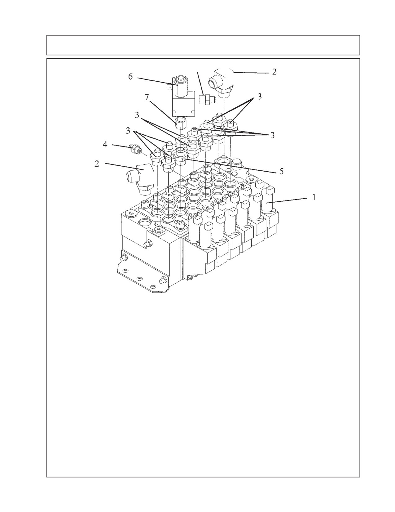
Mounting Component ID - Control Valve Fittings
Item Part No.
Qty Description
02981888
--
Valve & Fittings Asy, 6 Spool
1
02981370
1
Valve Asy w/o Fittings
2
02090800
2
Adapter Hyd, Elbow 12MB - 12MJ 90°
3
02972177
11
Adapter Hyd, Straight 10MB - 6MJ
4
03200284
1
Adapter Hyd, Straight 6MB - 4MJ
5
02981889
1
Adapter Hyd, Straight 10MB - 6MJ
6
02972208
1
Valve Solenoid Asy
7
02975438
1
Adapter Hyd, Straight 8MB - 8FJX
8
02981890
1
Adapter Hyd, Straight 8MB - 6MJ
11 - 21
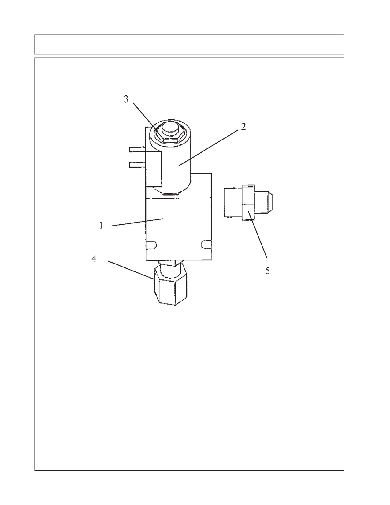
Mounting Component ID - Hydraulic Lock Valve
Item Part No.
Qty.
Description
02972208
--
Solenoid Valve Asy
1
02971425
1
Seal Kit, f/ solenoid Valve
2
02975198
1
Coil, 12V- DC w/Dual 8-32NF Studs
3
02975199
1
Cartridge, Solenoid Valve
4
02975438
1
Adapter Hyd, Straight 8MB-6FJX
5
02981890
1
Adapter Hyd, Straight 5MB - 6MJ
11 - 22
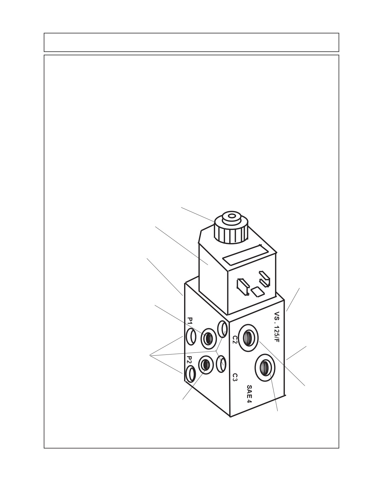
Mounting Component ID - DIVERTER VALVE
Door / Swing Cylinder Diverter Valve. Asy: P/N 02977622
The Diverter valve is a electrical operated valve that allows the hydraulic pressure to be
shared to operate two (or more if valves are stacked) funtions with a single pressure supply. This
valve is strictly a diverter valve and is designed to direct the pressure, not regulate the flow or
pressure.
The Port openings on this diverter valve are marked with letter number codes which show
wich port is connected to which hose and where that hose connect on other end (See Figure 18)
Port
Function & Connection
P1
Hose Hydraulic Pressure from Door / Swivel (B) Port on Control Valve
P2
Hose Hydraulic Return to Door / Swivel (A) Port on Control Valve
C1
Hose to Head Swivel Cylinder Base End
C2
Hose to Door Cylinder Base End
C3
Hose to Door Cylinder Rod End
C4
Hose to Head Swivel Cylinder Rod End
Electric solenoid retaing knob
Electric Solenoid
These 2 threaded holes on back
C1 Port this
side for mounting diverter valve
side
(Not
to frame (Not Seen)
Seen), to head
swivel cyl base
end
P1 Port, Pressure from Control
C4 Port this
Valve door / swivel port of control
side
(Not
valve
Seen), to
head swivel
These 4 holes are through holes
cyl rod end
that would be used if this were a
stacking valve to stack two (or
more) valves together. These holes
are not used in this application.
C2 Port, to
P2 Port, Return to control
door cyl base
valve door / swivel port of
end
control valve
C3 Port, to
door cyl Rod
end
11 - 23
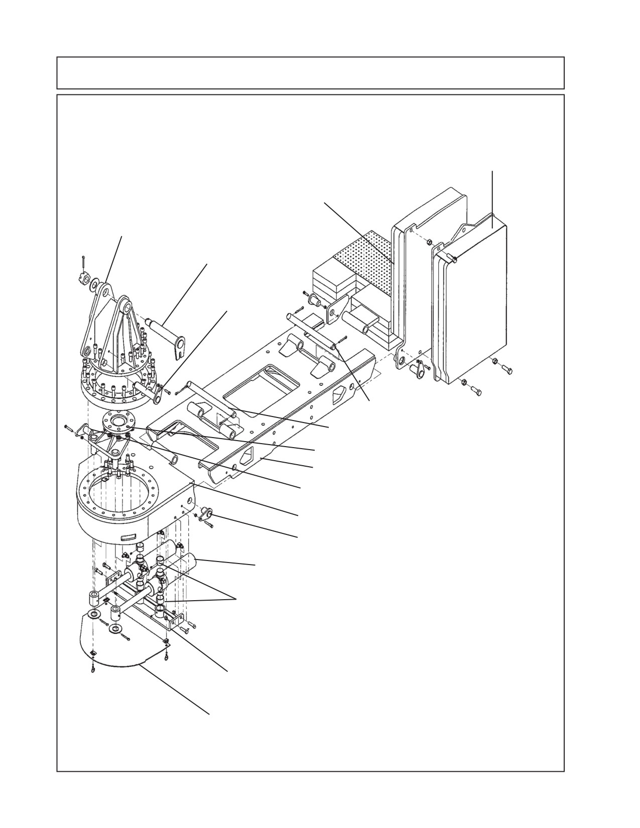
Mounting Component ID - Under Mnt Frame Asy 24’/30’
Under Mount Frame Asy (24 & 30 ft are the
same except for the LH weight)
30 ft model only
LH Counter Weight
Turret Asy, Machined
Turret / Boom Mount Pin
Lift Cyl Pin
Weight Attaching Pin, Long Pin
Boom Mount Attaching Pin, Long Pin
Turret Cylinder Link
Center Section Frame Weldment
Boom Mount Attaching Pin, Medium Pin
Boom Mount, Machined
Boom Mount Attaching Pin, Short Pin
Swing Cylinders
Swing Cylinder Pivot Bushings
Swing Cylinder Trunnion Mount Weldment
Swing Cylinder Cover
11 - 24
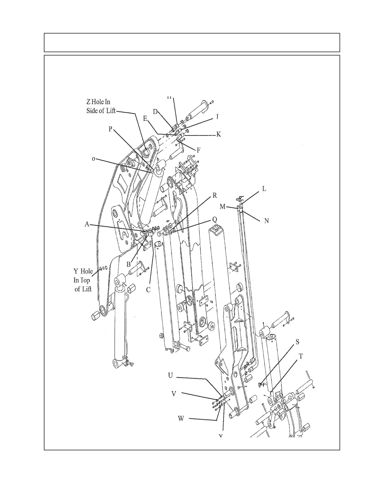
Mounting Component ID - Hyd Hose Connections
24 FT Boom
11 - 25
Mounting Component ID - Hyd Hose Connections
24 FT Boom
Part No.
Qty.End-1
End-2
Description
02981823
1
Y(MJ)
Z(FJX)
Hose, #4 - 4MJ - 4FJX - 76" Lg. - Yel Tie - Door (Lift Sect'n)
02981824
1
Y(MJ)
Z(FJX)
Hose, #4 - 4MJ - 4FJX - 76" Lg. - Yel/Wht Tie - Door (Lift Sect'n)
02981828
1
Y(MJ)
Z(FJX)
Hose, #4 - 4MJ - 4FJX - 76" Lg. - Grn Tie - Swivel (Lift Sect'n)
02981829
1
Y(MJ)
Z(FJX)
Hose, #4 - 4MJ - 4FJX - 76" Lg. - Grn/Wht Tie - Swivel (Lift Sect'n)
02981830
1
Y(MJ)
Z(FJX)
Hose, #6 - 6MJ - 6FJX - 76" Lg. - Yel Tie - Ext'n (Lift Sect'n)
02981831
1
Y(MJ)
Z(FJX)
Hose, #6 - 6MJ - 6FJX - 76" Lg. - Yel/Wht Tie - Ext'n (Lift Sect'n)
02981832
1
Y(MJ)
Z(FJX)
Hose, #6 - 6MJ - 6FJX - 76" Lg. - Red Tie - Tilt (Lift Sect'n)
02981833
1
Y(MJ)
Z(FJX)
Hose, #6 - 6MJ - 6FJX - 76" Lg. - Red/Wht Tie - Tilt (Lift Sect'n)
02981834
1
Y(MJ)
O(FJX) Hose, #6 - 6MJ - 6FJX - 96" Lg. - Blu Tie - Dipper (Dipper Sect'n)
02981835
1
Y(MJ)
P(FJX)
Hose, #6 - 6MJ - 6FJX - 96" Lg. - Blu/Wht Tie - Dipper (Dipper Sect'n)
02981836
1
Z(MJ)
R(FJX)
Hose, #6 - 6MJ - 6FJX - 88" Lg. - Yel Tie - Ext'n (Dipper Sect'n)
02981837
1
Z(MJ)
Q(FJX) Hose, #6 - 6MJ - 6FJX - 88" Lg. - Yel/Wht Tie - Ext'n (Dipper Sect'n)
02981838
1
Z(MJ)
V(FJX)
Hose, #4 - 4MJ - 4FJX - 176" Lg. - Yel Tie - Door (Dipper Sect'n)
02981839
1
Z(MJ)
U(FJX)
Hose, #4 - 4MJ - 4FJX - 176" Lg. - Yel/Wht Tie - Door (Dipper Sect'n)
02981840
1
Z(MJ)
X(FJX)
Hose, #4 - 4MJ - 4FJX - 176" Lg. - Grn Tie - Swivel (Dipper Sect'n)
02981841
1
Z(MJ)
W(FJX) Hose, #4 - 4MJ - 4FJX - 176" Lg. - Grn/Wht Tie - Swivel (Dipper Sect'n)
02981842
1
Z(MJ)
T(FJX)
Hose, #6 - 6MJ - 6FJX - 176" Lg. - Red Tie - Tilt (Dipper Sect'n)
02981843
1
Z(MJ)
S(FJX)
Hose, #6 - 6MJ - 6FJX - 176" Lg. - Red/Wht Tie - Tilt (Dipper Sect'n)
02981846
1
C(FJX)
F(FJX)
Hose, #16-16FJX-16FJX90°-102" Lg.-Red Tie-Motor-P (Lift Sect'n)
02981847
1
A(FJX)
D(FJX)
Hose, #16-16FJX-16FJX90°-102" Lg.-Org Tie-Motor-R (Lift Sect'n)
02981848
1
K(FJX)
L(FJX)
Hose, #16-16FJX-16FJX-54" Lg.-Red Tie-Motor-P (Dipper Sect'n)
02981849
1
H(FJX)
N(FJX)
Hose, #16-16FJX-16FJX-58" Lg.-Org Tie-Motor-R (Dipper Sect'n)
02981850
1
B(FJX)
E(FJX)
Hose, #12-12FJX-12FJX90°-102"Lg.-Blu Tie-Case Drain (Lift Sect'n)
02981851
1
J(FJX)
M(FJX) Hose, #12-12FJX-12FJX-56" Lg.-Blu Tie-Case Drain (Dipper Sect'n)
NOTE 1:
Hose End-1 & End-2, these are where the ends of that hose connect, the letter shows
location of that end and ( ) show type hose fitting at that end.
NOTE 2:
The hoses have plastic ties on the to show which hose is which. The colors are
abreviated to YEL = Yellow, YEL/W = Yellow with Whiter stripe, GRN = Green, GRN/
W = Green with White Stripe, RED = Red, RED/W = Red with White Stripe, BLU -
Blue, BLU/W = Blue with White Stripe, ORG = Orange, ORG/W = Orange with White
Stripe.
NOTE 3:
(Sect'n) = Location where hose is located on boom
11 - 26
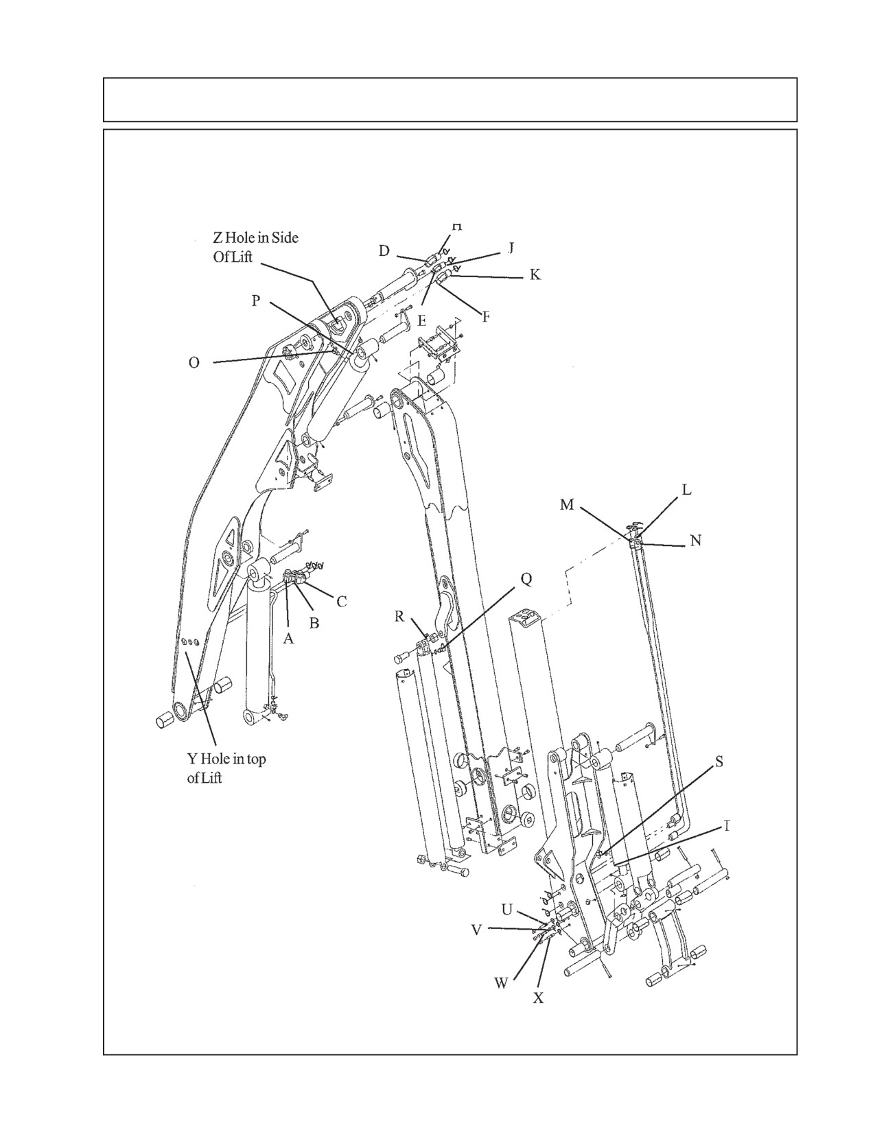
Mounting Component ID - Hyd Hose Connections
30 FT Boom
11 - 27
Mounting Component ID - Hyd Hose Connections
30 FT Boom
Part No.
Qty.End-1
End-2
Description
02981879
1
Y(MJ)
Z(FJX)
Hose, #4 - 4MJ - 4FJX - 115" Lg. - Yel Tie - Door (Lift Sect'n)
02981880
1
Y(MJ)
Z(FJX)
Hose, #4 - 4MJ - 4FJX - 115" Lg. - Yel/Wht Tie - Door (Lift Sect'n)
02981855
1
Y(MJ)
Z(FJX)
Hose, #4 - 4MJ - 4FJX - 115" Lg. - Grn Tie - Swivel (Lift Sect'n)
02981856
1
Y(MJ)
Z(FJX)
Hose, #4 - 4MJ - 4FJX - 115" Lg. - Grn/Wht Tie - Swivel (Lift Sect'n)
02981857
1
Y(MJ)
Z(FJX)
Hose, #6 - 6MJ - 6FJX - 115" Lg. - Yel Tie - Ext'n (Lift Sect'n)
02981858
1
Y(MJ)
Z(FJX)
Hose, #6 - 6MJ - 6FJX - 115" Lg. - Yel/Wht Tie - Ext'n (Lift Sect'n)
02981859
1
Y(MJ)
Z(FJX)
Hose, #6 - 6MJ - 6FJX - 115" Lg. - Red Tie - Tilt (Lift Sect'n)
02981860
1
Y(MJ)
Z(FJX)
Hose, #6 - 6MJ - 6FJX - 115" Lg. - Red/Wht Tie - Tilt (Lift Sect'n)
02981861
1
Y(MJ)
O(FJX) Hose, #6 - 6MJ - 6FJX - 135" Lg. - Blu Tie - Dipper (Dipper Sect'n)
02981862
1
Y(MJ)
P(FJX)
Hose, #6 - 6MJ - 6FJX - 135" Lg. - Blu/Wht Tie - Dipper (Dipper Sect'n)
02981863
1
Z(MJ)
R(FJX)
Hose, #6 - 6MJ - 6FJX - 125" Lg. - Yel Tie - Ext'n (Dipper Sect'n)
02981864
1
Z(MJ)
Q(FJX) Hose, #6 - 6MJ - 6FJX - 125" Lg. - Yel/Wht Tie - Ext'n (Dipper Sect'n)
02981865
1
Z(MJ)
V(FJX)
Hose, #4 - 4MJ - 4FJX - 214" Lg. - Yel Tie - Door (Dipper Sect'n)
02981866
1
Z(MJ)
U(FJX)
Hose, #4 - 4MJ - 4FJX - 214" Lg. - Yel/Wht Tie - Door (Dipper Sect'n)
02981867
1
Z(MJ)
X(FJX)
Hose, #4 - 4MJ - 4FJX - 214" Lg. - Grn Tie - Swivel (Dipper Sect'n)
02981868
1
Z(MJ)
W(FJX) Hose, #4 - 4MJ - 4FJX - 214" Lg. - Grn/Wht Tie - Swivel (Dipper Sect'n)
02981869
1
Z(MJ)
T(FJX)
Hose, #6 - 6MJ - 6FJX - 214" Lg. - Red Tie - Tilt (Dipper Sect'n)
02981870
1
Z(MJ)
S(FJX)
Hose, #6 - 6MJ - 6FJX - 214" Lg. - Red/Wht Tie - Tilt (Dipper Sect'n)
02981873
1
C(FJX)
F(FJX)
Hose, #16-16FJX-16FJX90°-140" Lg.-Red Tie-Motor-P (Lift Sect'n)
02981874
1
A(FJX)
D(FJX)
Hose, #16-16FJX-16FJX90°-140" Lg.-Org Tie-Motor-R (Lift Sect'n)
02981875
1
K(FJX)
L(FJX)
Hose, #16-16FJX-16FJX-94" Lg.-Red Tie-Motor-P (Dipper Sect'n)
02981876
1
H(FJX)
N(FJX)
Hose, #16-16FJX-16FJX-98" Lg.-Org Tie-Motor-R (Dipper Sect'n)
02981877
1
B(FJX)
E(FJX)
Hose, #12-12FJX-12FJX90°-140"Lg.-Blu Tie-Case Drain (Lift Sect'n)
02981878
1
J(FJX)
M(FJX) Hose, #12-12FJX-12FJX-96" Lg.-Blu Tie-Case Drain (Dipper Sect'n)
NOTE 1:
Hose End-1 & End-2, these are where the ends of that hose connect, the letter
shows location of that end and ( ) show type hose fitting at that end.
NOTE 2:
The hoses have plastic ties on the to show which hose is which. The colors are
abreviated to YEL = Yellow, YEL/W = Yellow with Whiter stripe, GRN = Green,
GRN/W = Green with White Stripe, RED = Red, RED/W = Red with White Stripe,
BLU - Blue, BLU/W = Blue with White Stripe, ORG = Orange, ORG/W = Orange
with White Stripe.
NOTE 3:
(Sect'n) = Location where hose is located on boom
11 - 28
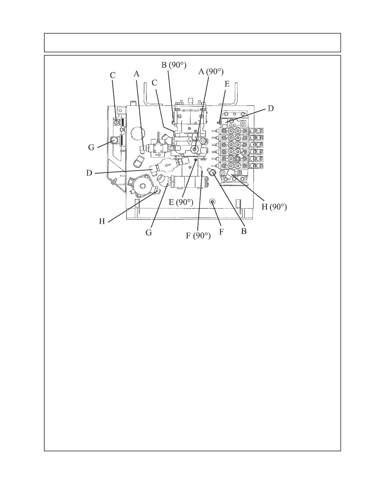
Mounting Component ID - Motor & Boom Pump Hose
Item Part No.
Qty. Description
A
02981427
1
Hose, 8FJX - 8FJX 90° - 24" Lg. w/Red Tie (Charge Filter to Pump)
B
02981428
1
Hose, 8FJX - 8FJX 90° - 21" Lg. w/ Blu Tie (Case Drain to Tank)
C
02981429
1
Hose, 12FJX - 12FJX - 23" Lg. (Pump to Suction Filter) hose under
pump and cannot be seen in drawing.
D
02981430
1
Hose, 12FJX - 12FJX - 31" Lg. w/ Red Tie (Pressure Filter to Supply)
E
02981431
1
Hose, 4FJX - 4FJX 90° - 35" Lg. w/ Red Tie (Pump Load Sense to
Valve (PX)
F
02981432
1
Hose, 4FJX - 4FJX 90° - 20" Lg. w/ Blu Tie (Pump Regulator to Tank)
F
------------
1
Hose, #4 Hose f/ Base end of Stabilizer Cyl to Tank port Via a Tee fitting.
G
02981433
1
Hose, 20FJX - 12FJX - 24" Lg. (Pump to Suction Filter)
H
02981462
1
Hose, 12FJX - 12FJX 90° - 20" Lg. w/ Org Tie (Valve Return to Tank)
NOTE: Hoses are not shown in drawing above, this is for clarity. The hose routing is for the hoses which
connect from one point to the other. Use the instructions and hose description listed to follow hose
routing.
Example: Hose - A connects to one end marked A and the other end of hose connects to the other item
marked A. This is done with the other letters as well, the hose must connect to the same letter markings
on each end as in drawing. Some hose will be marked with a colored plastic tie.
Some hose will have a straight fitting or a 90° fitting. This is to allow hoses to be routed to where they
clear other items, when connecting hose put the end on that has the correct fitting as noted in drawing
with (90°) or the straight fitting if note marked hose routing that is to make hoses clear other items. Do
Not connect hose to different letter items, all hose end must connect to the same letter on both ends.
TO ID HOSES: Always check Size, Length, Fittings and Color Plastic Tie to identify the hoses. Some
hoses will have the same color tie but the size, length or fittings will be different.
11 - 29
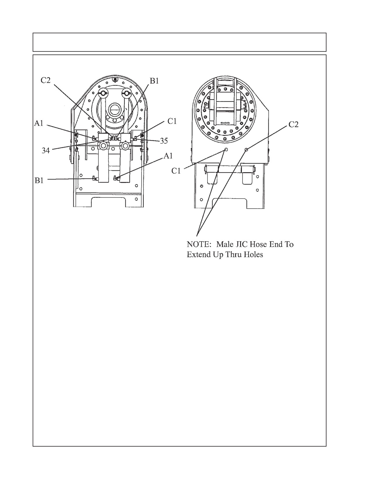
Mounting Component ID - Swing Cyl. Hose (24’/30’)
Item Part No. Qty Description
A1
02981825
1
Hose, #6-6FJX-6FJX-28"Lg
B1
02981825
1
Hose, #6-6FJX-6FJX-28"Lg
C1
02981826
1
Hose, #6-6FJX-6MJ-16"Lg- Geen Tie
C2
02981827
1
Hose, #6-6FJX-6MJ-16"Lg- Green / White Tie
34
02968832
1
Plastic Tie, Green
35
02968833
1
Plastic Tie, Green / White
NOTE:
Hose are not shown in drawing, this is for clarity. The hose routing is for hoses which
connect from one point to the other. Use the instructions and hose descriptions listed to
follow hose routing.
Example: Hose - A1 connects to one end marked A1 and the other end connects to the
other connection marked A1. This is done with the other letters as well, the hose must connect to
the same letter mark on each end. Some hose have a plastic colored tie on it to ID hose and
location.To ID hoses always check hose size, length and colored plastic tie.
11 - 30
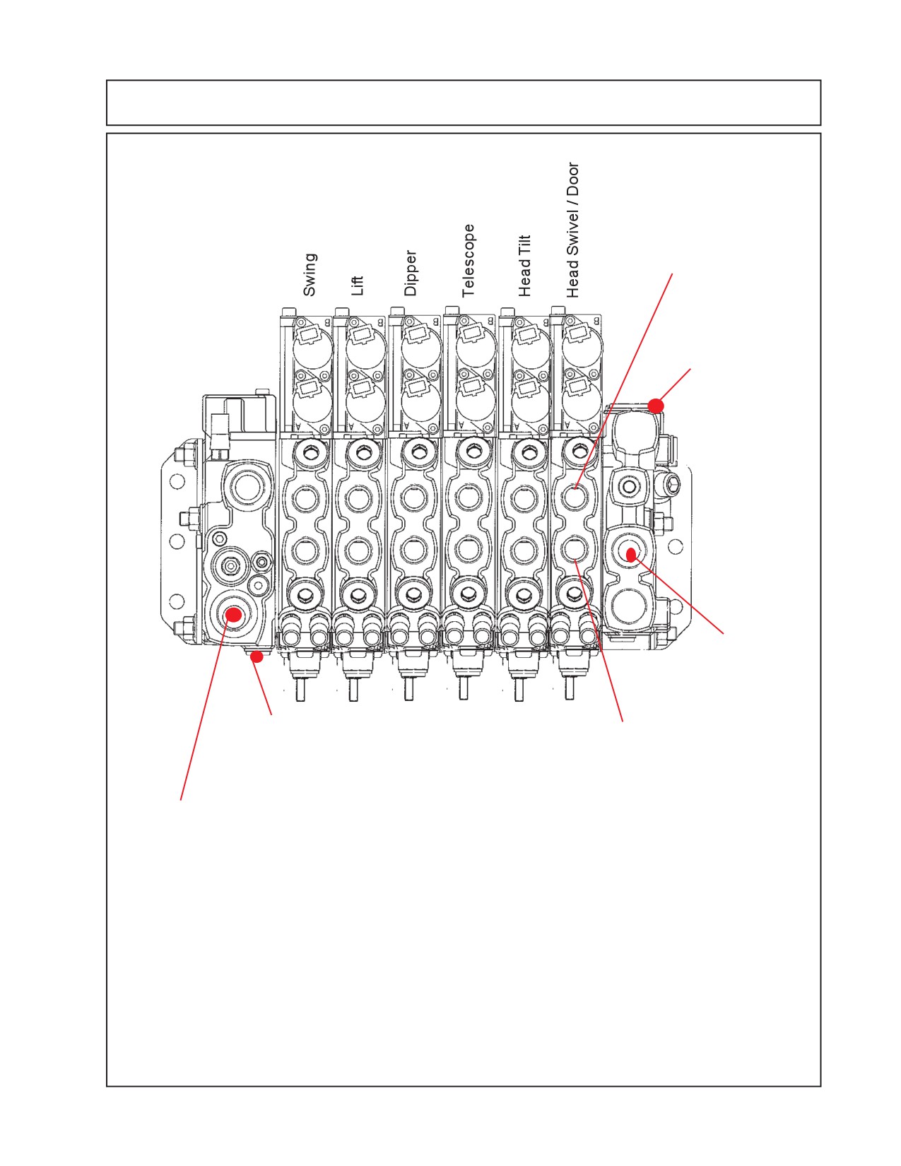
Mounting Component ID - Cyl Cntrl Valve Connections
Service Connection
Port, B-Port. (B)
Testing Port for
Pilot Pressure Test
(PS)
B B B B B B
A
A
A
A
A
A
Tank
Return
Connection
T2
Port Load Sense
Service Port Connection,
Signal (PL)
A-Port (A)
Pump
Pressure
Connection
(P1)
11 - 31
Mounting Component ID - Cyl Cntrl Valve Connections
HYDRAULIC HOSE CODES
Hydraulic Hose Band Mark Color Codes: Hose's and/or fittings are marked with a
Color Coded Plastic Band around it. Some Bands are a solid Color and some have a Colored
with a Stripe. The purpose of the colored bands are to provide a quick reference for hose and port
connection. A metal band is also attachted to the hose, on that band is an Alamo Industrial Part
Number for reference if needing a replacement hose. Always Check Hose Size, Color Code
& Part Number
Boom Cylinder Circuit Hoses connections from Control Valve:
Color Tie
(Code) Hose Size
Port
Hyd. Function
Green
G
SAE # 6
A
Swing, Back (Rod End)
Green / White
G/W
SAE # 6
B
Swing, Forward (Base End)
Orange
OR
SAE # 6
B
Lift, Down (Rod End)
Orange / White
OR/W
SAE # 6
A
Lift, Up (Base End)
Blue
B
SAE # 6
A
Dipper, In (Rod End)
Blue / White
B/W
SAE # 6
B
Dipper, Out (Base End)
Yellow
Y
SAE # 6
B
Telescope, In (Rod End)
Yellow / White
Y/W
SAE # 6
A
Telescope, Out (Base End)
Red
R
SAE # 6
A
Head Tilt, Up (RodEnd)
Red / White
R/W
SAE # 6
B
Head Tilt, Down (Base End)
Green
G
SAE # 4
A
Swivel, CW (Rod End)
Green / White
G/W
SAE # 4
B
Swivel, CCW (Base End)
Yellow
Y
SAE # 4
A
Door, Open (Rod End)
Yellow / White
Y/W
SAE # 4
B
Door, Closed (Base End)
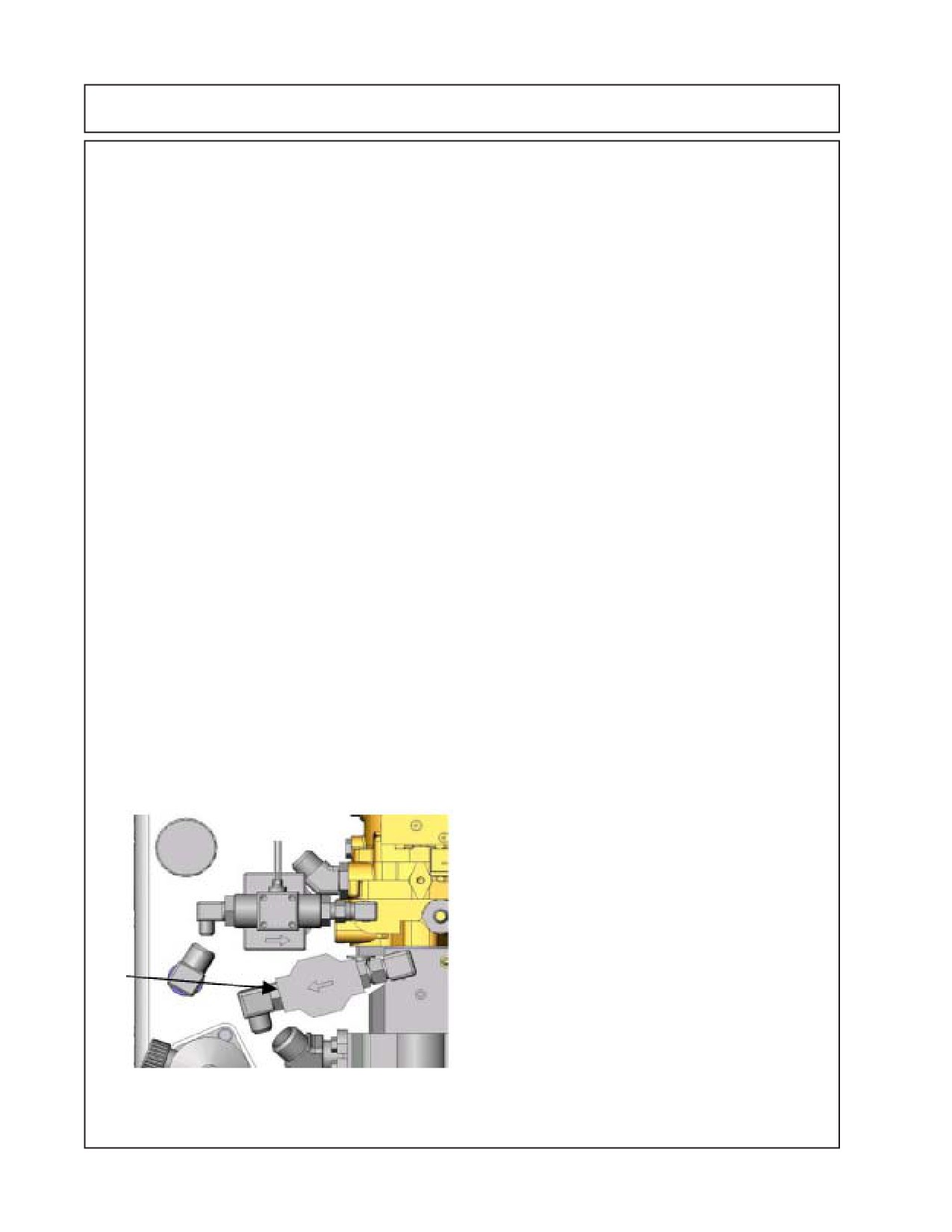
Valve Pressure Filter Switch
11 - 32
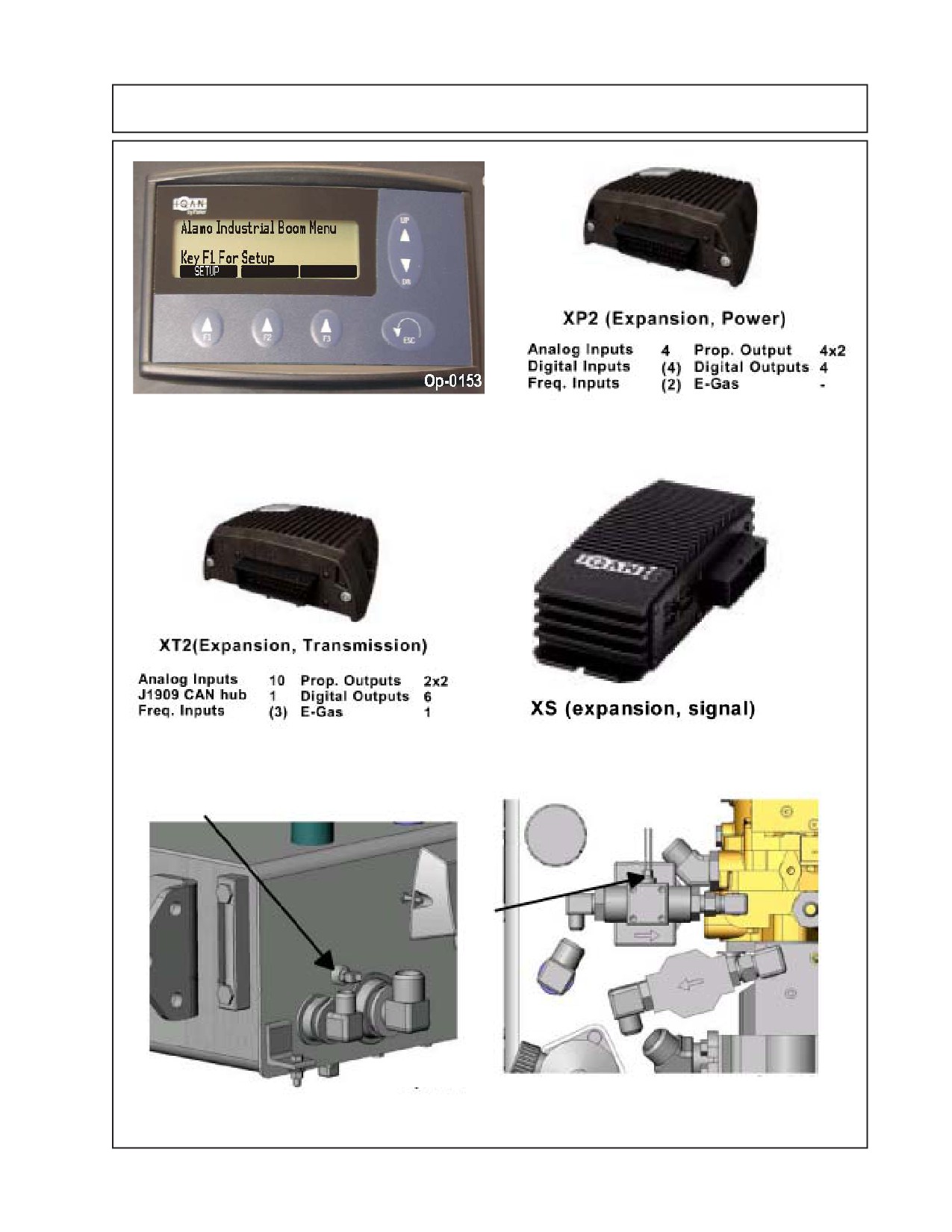
Component Identification
XP2 (Expansion, Power)
Iqan Display Unit
XT2 (Expansion, Transmission)
XS (Expansion, Signal)
Tank Temperature Sensor
Charge Pressure Filter Switch
11 - 33
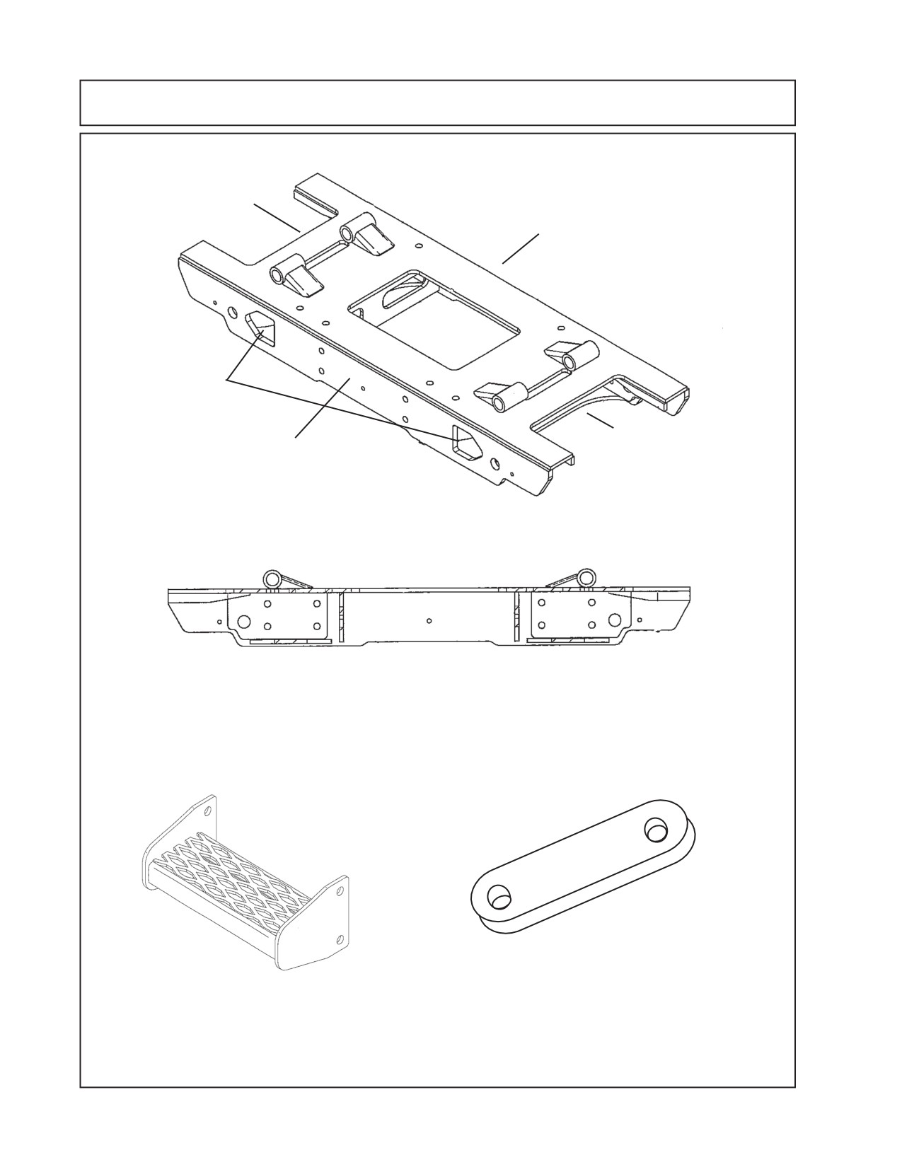
Component Identification
RH Side
of Tractor
Rear of
Tractor
Install with these
openings to front
of tractor
LH Side of
Front of
Tractor
Tractor
Rear View
P/N 02981168 Center Section Under Mount Frame Wldmnt
P/N 02980694 LH Rear Top Axle strap
P/N 02976633 LH Side Step Wldmnt
11 - 34
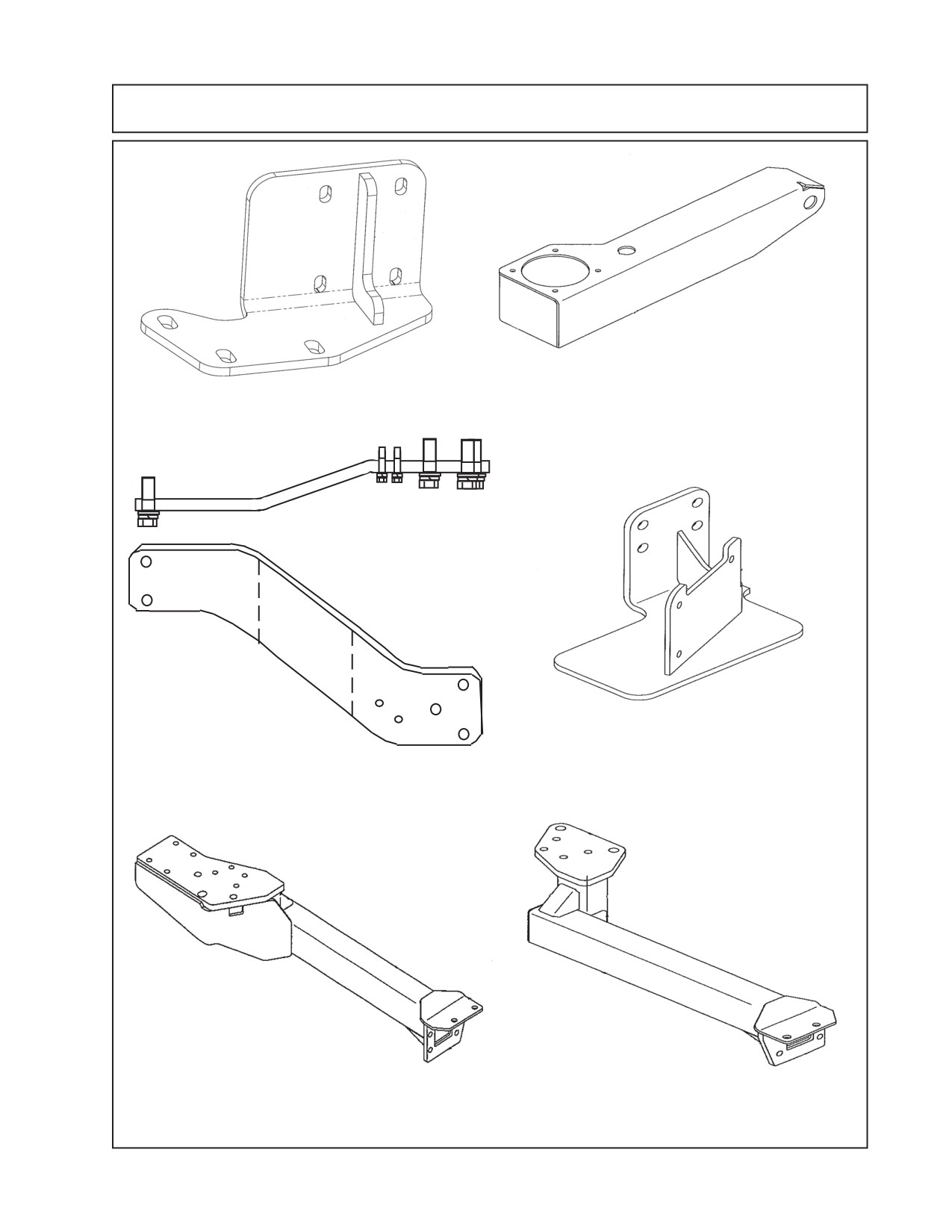
Component Identification
P/N 02980933 Exhaust Relocation Bracket
P/N 02981415 Arm Rest Controller Mount
Weldment
123
1233
12
12
123
1233
12
12
123
1233
1223
123
123
123
123
RH Side Shown, LH
Tractor End
Bent opposite way
P/N 02981725 Battery Relocation
P/N 02981404 Tank Rail Mount RH
Bracket Weldment
&
P/N 02981405 Tank Rail Mount LH
P/N 02982006 Rail Weldment
P/N 02982005 Rail Weldment
LH Rear
RH Rear
11 - 35
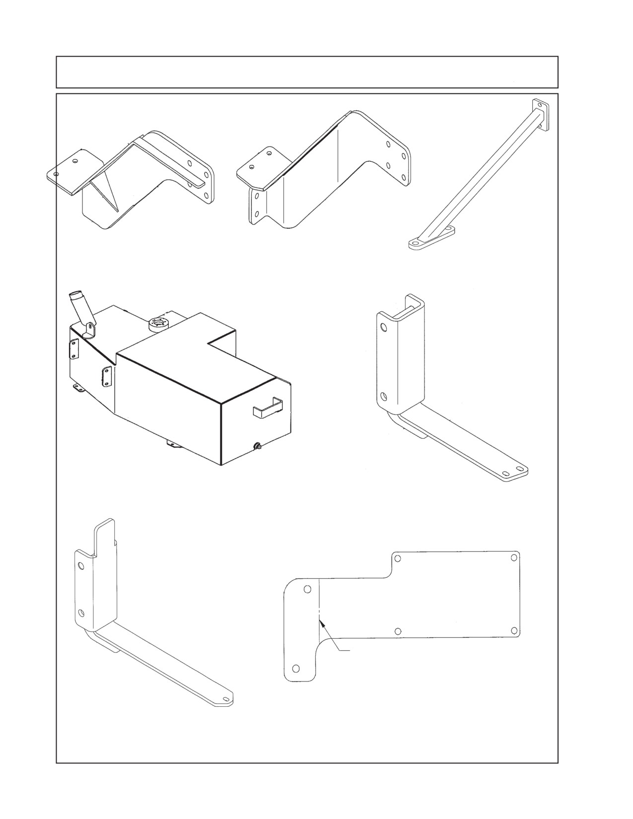
Component Identification
P/N 02982014 Rail
P/N 02982015 Rail
P/N 02982022 Boom
Weldment RH Front
Weldment LH Front
Rest Stabilizer Wldmnt
P/N 02982198 Fuel Tank
Weldment - 51 Gals.
02982206 Fuel Tank Brkt
Weldment - Front
Bend Upward 60° Here
P/N 02982324 Mount
Plate - Iqan Display Mount
02982207 Fuel Tank Brkt
Weldment - Rear
11 - 36
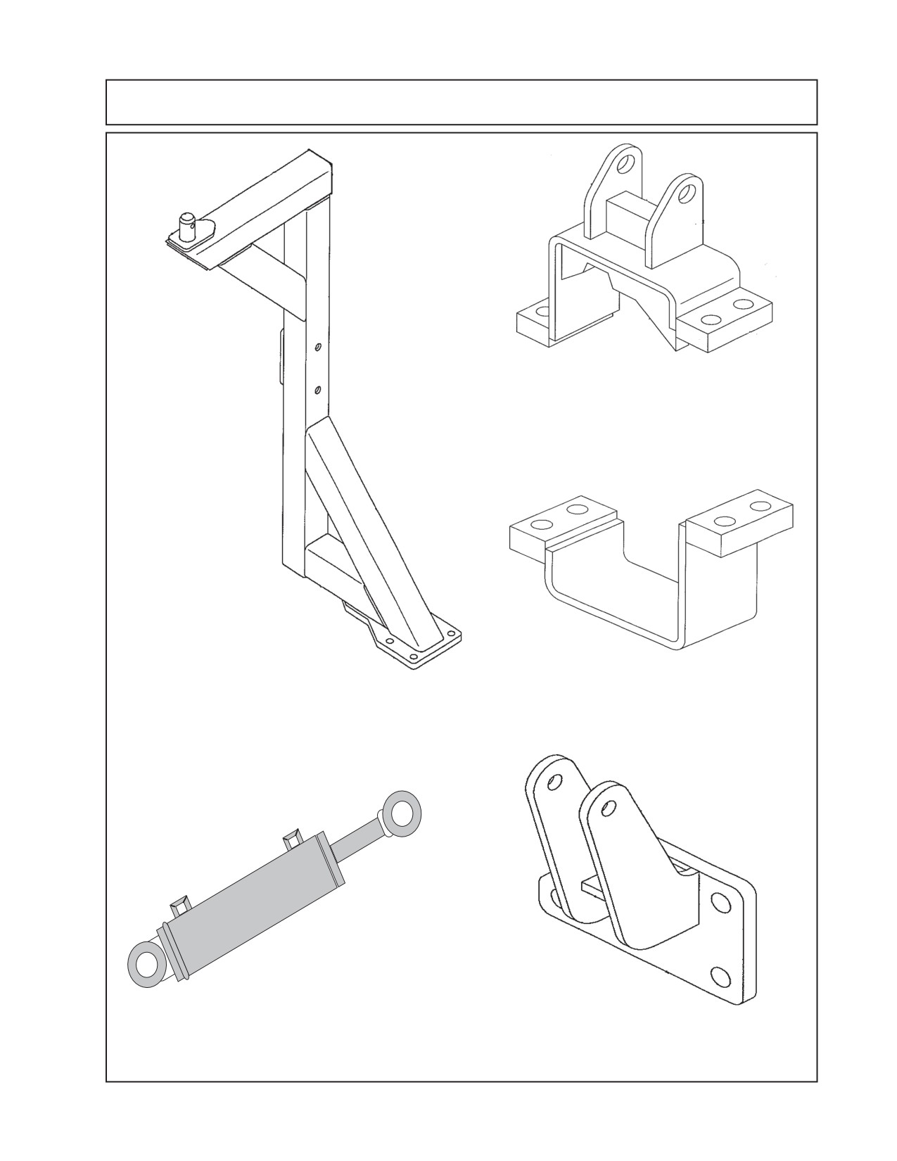
Component Identification
P/N 02983143 Front Axle Stabilizer
Top Bracket Weldment (Included in
Front Axle Stabilizer Kit Only for 4
WD Tractors)
P/N 02982314 for 24ft
Boom Rest Weldment
&
P/N 02982025 for 30ft
P/N 02983144 Front Axle Stabilizer
Boom Rest Weldment
Bottom Bracket Weldment (Included
in Front Axle Stabilizer Kit Only for 4
WD Tractos)
123
123
1234
234
234
234
12
123
2
123
123
2345
123456
123456
123456
1234567
234567
234567
34567
34567
P/N 02981316 Cylinder Asembly
P/N 02982320 Cyl Support
(Included in Front Axle Stabilizer Kit Only)
Weldment (Included in Front Axle
Stabilizer Kit Only)
11 - 37
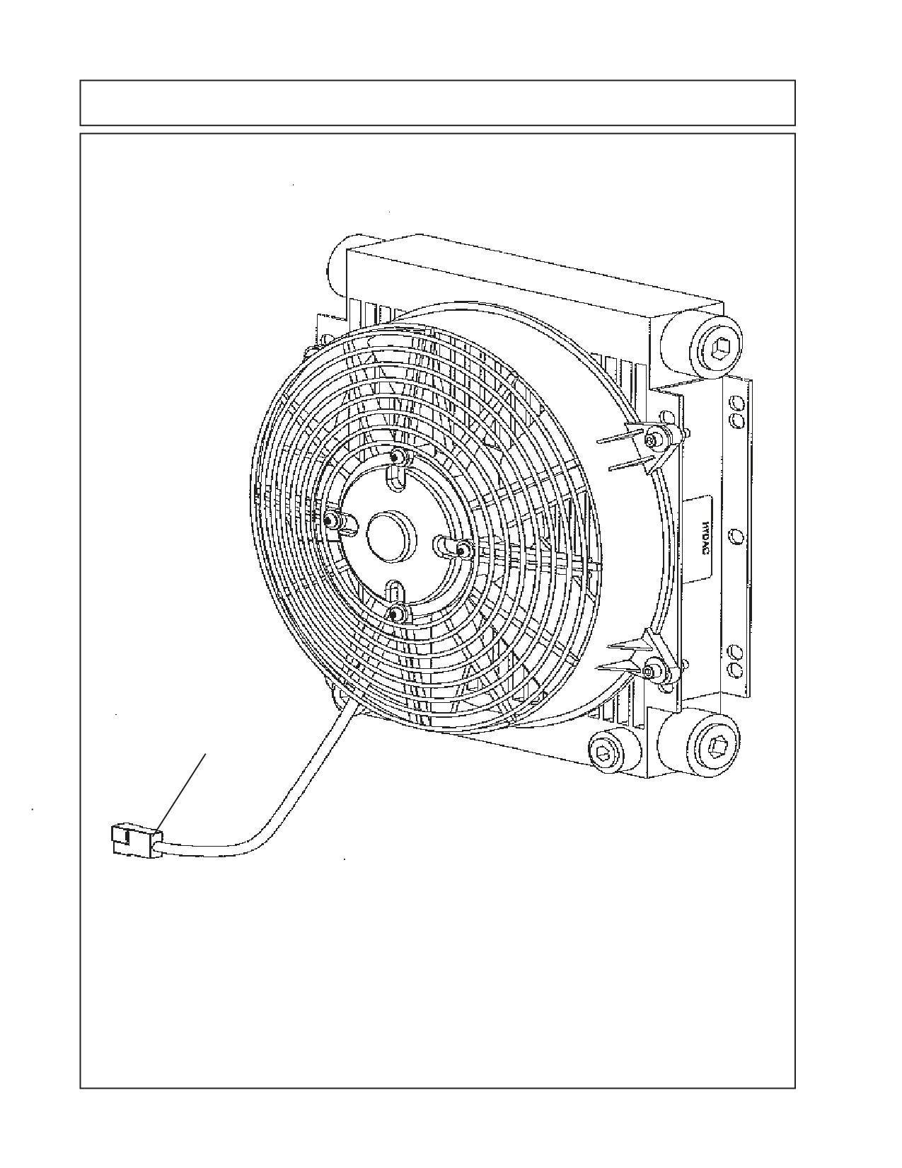
Component Identification
Two Wires in plug
1 - Blue Wire + Connection
1- Black Wire - Connection
Connecte to R1 Connec-
tion of Exterior Wire
Harness
Oil Cooler / Fan Assembly
P/N 02981377
11 - 38
Section 12
MAVERICK
New Holland Tractor
TS-100A, 115A, 125A, 135A
PRE-DELIVERY INSPECTION
CHECKLIST
Maverick (NH TS-100A, 115A, 125A, 135A, Asy. Manl) 01/05
Section12 - 1
MAVERICK PRE-DELIVERY INSPECTION CHECKLIST
Pre-Operation Inspection: Check the following items before operating the unit to assure
that they are properly assembled. (See following page 1-4 for component location)
Saftey Equipment:
-----
Operators Manual is with Unit.
-----
The Safety Decals are installed as listed in the Assembly Manual.
-----
Valve operation plate is installed.
-----
Operators cage or Tractor Cab is in place.
-----
Deflectors are installed on the Mower Head.
-----
Tractor Rops or Cab with seatbels installed properly.
Frame and Boom: (NH TS-100A, 115A, 125A & 135A)
-----
Axle Plate Bolts are torqued to 280 ft. lbs.
-----
Boom Rest Axle Plate Bolts are torqued to 280 ft. lbs.
-----
Front Rail Bolts are torqued to 425 ft. lbs.
-----
Front Support Bolts at tractor are torqued to 355 ft. lbs.
-----
Rear Rail Bolts torque to 425 ft lbs.
-----
Rotator bolts torque to 120 ft. lbs.
-----
All Welds inspected toinsure proper welds and locations.
Hydraulic System:
-----
Oil Level in Hydraulic Tank is within the sight gauge.
-----
Hose connections are tight.
-----
Hoses do not have any kinks or twist in them.
-----
Front Pump Shaft adapter bolts are tight..
-----
Front Pump Shaft Coupler / Drive Shaft is lubricated and has an anti-seize compound
on the Splines of Pump and Shafts.
-----
The Pump Drive Shaft has correct alignment.
-----
Suction Hose has no leaks or kinks.
Rotary Mower Head:
-----
Skid Shoe Bolts are torqued to 120 ft. lbs.
-----
Spindle Housing Bolts are torqued to 400 ft. lbs.
-----
The Spindle Housing is properly lubricated.
-----
Motor Bolts are torqued to 120 ft. lbs.
-----
Blade Carrier (Bar) Bolts torque to 400 ft. lbs.
-----
Blade Bolts are torqued and the retainings Pins are in place.
-----
Blades Swing freely.
Boom:
-----
Boom Telesoping Bearings Adjusted completely inward.
-----
All Hoses tightened and no leaks.
-----
All hoses secured to where they will not rub, get pinched or hanging down where they may
catch on something.
-----
All Decals installed
-----
Pump Primed and Pressure adjusted if needed (only applys to Pump for Cylinder control.
Maverick (NH TS-100A, 115A, 125A, 135A, Asy. Manl) 01/05
Section 12 - 2
MAVERICK PRE-DELIVERY INSPECTION CHECKLIST
Pre-Operation Inspection: Check the following items before operating the unit to assure
that they are properly assembled.
Flail Mower Head:
___ Skid Shoe Bolts are torqued to 120 ft-lbs.
___ Motor Bolts are torqued to 120 ft-lbs
___ Belt Alignment& tension adjustment is correct
___ Cutter shaft bearings are properly lubricated
___ Roller bearings are properly lubricated
___ Blades swing freely
Tractor Mower Operation Inspection:
Using all Safety precautions, operate the Tractor and Mower unit for 30 minutes and
while the unit is running check the following items: Note! Only make adjustments after
the mower has been turned off and all motion has stopped and all hydraulic pressure
has been relieved.
___
Check for Hydraulic oil leaks at the hose connections
___
Operate the boom and mower head throughout its full range of motion and check
for hose's rubbing, pinching, or kinking.
___
Make sure the Return Filter Gauge is reading in the Green after Oil is warm.
___
Check the function of the Mower Head On-Off Valve and switch for proper function
___
Make sure that the tractor will not start with the mower on-off switch in the on
position.
___
Check the Blade Rotation for the Rotary Mower Head to make sure it is turning
Clockwise looking from the top of the mower deck.
___
Make sure the control valve boom movements agree with the valve operation decal.
___
Make Sure Boom Movement operates as expected and is smooth and under control
(no air in the control system)
___
Look for any unusual or excessive noise or vibrations.
___
Make sure the left rear wheel of the tractor stays on the ground when the boom is
fully extended horizontally with 200 lbs. placed on the outside of the mower head.
Post-Operation Inspection:
___ Check that the oil in the hydraulic tank has not turned milky in color or has foam on top.
___ Check that there are no loose fasteners or hardware.
Maverick (NH TS-100A, 115A, 125A, 135A, Asy. Manl) 01/05
Section12 - 3