New Holland. Cab 2 WD / 4 WD TS-100A, TS-115A, TS-125A, TS-135A. ASSEMBLY MANUAL - page 2
Battery Holder Relocation
Battery Holder Relocation:
1.
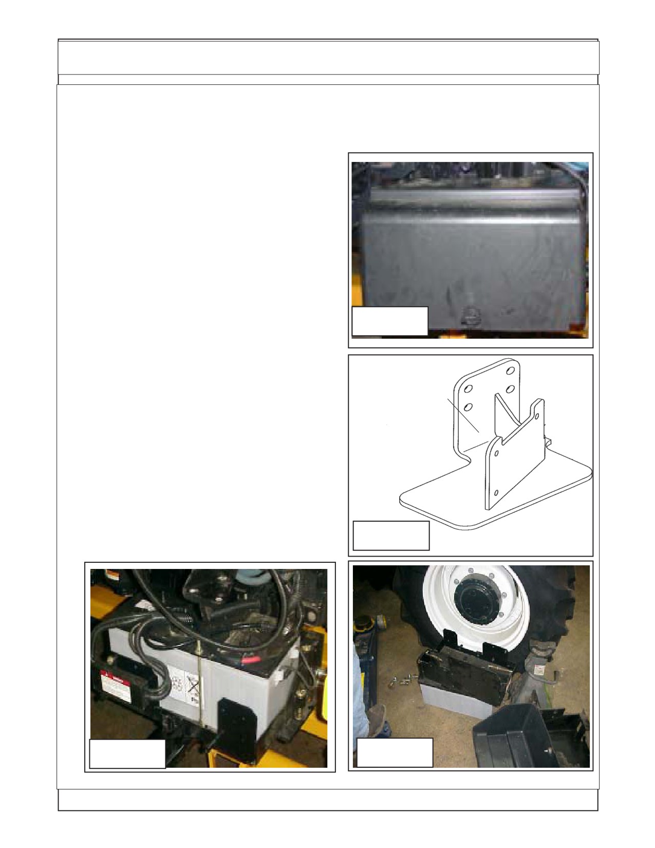
The Battery Relocation. The battery holder is
located on the RH side of the tractor (See Figure 1) .
It will have to be relocated. The mount kit will include
a battery relocation kit. The battery relocation kit
includes a mounting bracket (See Figure 2) that will
relocate the battery tray farther to the rear. This is
done so the Boom Swing will not hit battery when in
the transport position. The RH Step Will need to be
removed to allow access to relocate battery.
2.
Remove Factory Battery Cover, Battery,
Battery Tray and Battery Tray mount. Remove the
battery cover (See Figure 3), Remove the battery
cables from the battery. Remove the battery from
Figure 1
the battery tray. Unbolt the battery tray from the
tractors factory mount bracket. Remove the factory
mounting bracket from the tractor (See Figure 4).
Battery
3.
Install Replacement Battery Tray Bracket.
Relocation
Install the replacement battery tray bracket (See
Bracket
Figure 2) using the same bolts and holes as the
P/N
original bracket. This Bracket is designed to move
battery further back. Install original battery tray using
02981725
original hardware. Reinstall battery into batter tray
(See Figure 3). DO NOT reconnect battery cables at
this time, leave them off and make certain they do
not make contact with the battery connections as
you do not want the battery connected during instal-
lation. Replace the battery cover (See Figure 1) for
Figure 2
now this will protect battery and cover.
Figure 3
Figure 4
Maverick (NH TS-100A,115A ,125A,135A Asy. Man) 01/05
Section 5 - 2
Exhaust / Muffler Relocation
Exhaust / Muffler
Relocation:
1.
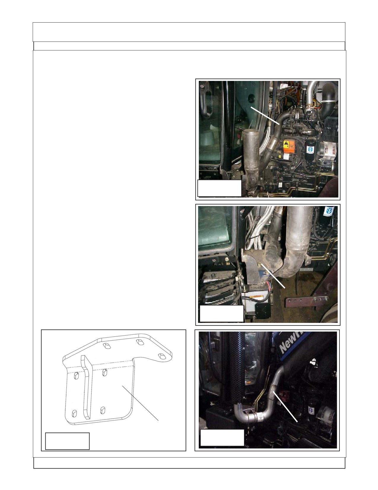
Remove The Exhaust . The Exhaust reloca-
tion kit will include a new mounting bracket, Bolting
Tractor Factory
Exhaust pipe to
hardware, replacement exhaust pipe from turbo to
Turbo
muffler. The Muffler needs to be removed first (See
Figure 5). Remove the Exhaust pipe to turbo (See
Figure 5). Remove the tractors factory Exhaust pipe
mounting bracket (See Figure 6).
2.
Install Exhaust Replacement Mounting
Bracket. The replacement exhaust mounting
bracket will bolt in the place of the factory mounting
bracket. The replacement bracket moves the ex-
Figure 5
haust inward towards the engine by about 5 to 6
inches. This is to give clearance of the boom and
exhaust system (See Figure 7).
3.
Install Replacement Exhaust Pipe. Install
the replacement exhaust pipe using the new clamp
furnished in kit. Fasten the new exhaust pipe to the
new exhaust bracket using the two factory u-Bolts
that were used on the original exhaust pipe (See
Figure 8).
4.
Reinstall the muffler to the exhaust pipe us-
ing the factory bolts and hardware. Check all the
bolts and components to the exhaust for tightness
Factory Exhaust
and fit.
Mount Bracket
Figure 6
Replacement
New Exhaust Pipe
Exhaust Bracket
Figure 8
P/N 02980917
Figure 7
P/N 02980933
Maverick (NH TS-100A,115A ,125A/,35A Asy. Man) 01/05
Section 5 - 3
Fuel Tank Replacement
Fuel Tank Replacement:
1.
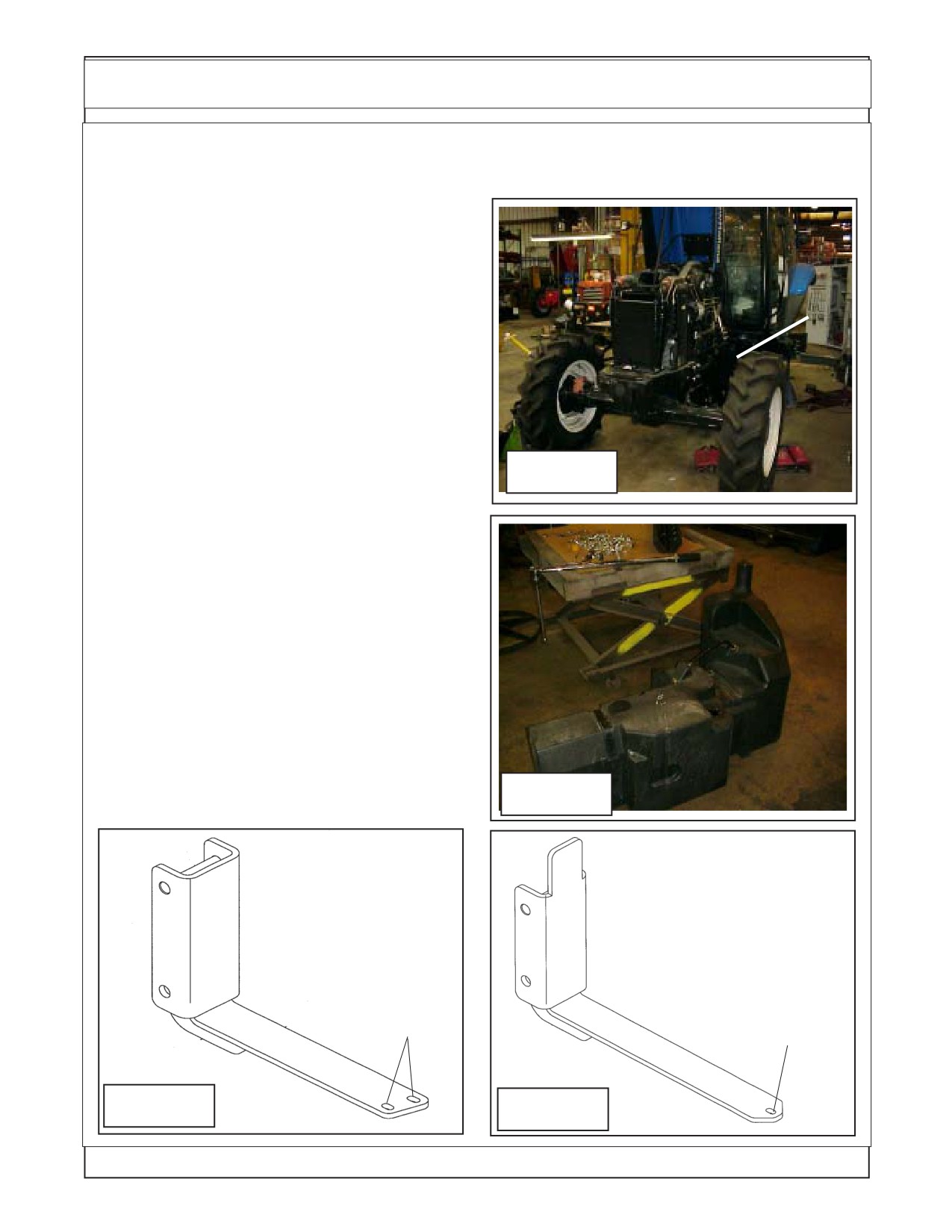
Remove RH Rear Tire and Wheel. Use
proper Floor jack to lift the RH Rear Wheel, Support
the tractor with proper jack stands rated appropri-
ately for the tractors weight. The RH rear tire and
wheel should be removed for this installation by
using a hoist to support and lift the wheel and tire
assembly. The tractors factory fuel tank is mounted
behind the RH rear tire and wheel (See Figure 9).
2.
Remove Tractors Factory Fuel Tank and
Remove RH
Mounting Brackets. The LH factory step will have to
Rear Tire &
be removed from the tractor before attempting to
Wheel
remove the fuel tank, the step will not be reused.
The factory fuel tank will need to drained of fuel. Use
an appropriate and safe method for pumping out
Figure 9
tank and for the storage of the fuel removed. The
Tank is removed by loosening and removing the
retaining straps that you will see around the tank
from the out side. DO NOT Attempt to remove tank
with fuel in it.
Store the fuel tank in an appropriate safe place away
from flames, extreme heat and or dusting dirty
conditions. The Fuel Pickup and Gauge sending unit
will need to be removed from the factory tank to be
installed in the new replacement tank later (See
Figure 10).
3.
Install Replacement Fuel Tank Mounting
Brackets. Remove the factory fuel tank mounting
brackets, there are two new mounting brackets that
will be supplied to mount the new tank. There is a
Figure 10
front and a rear bracket (See Figure 11 & 12).
Front Fuel Tank
Rear Fuel Tank
Bracket P/N
Bracket P/N
02982206
02982207
2
1
Holes
Hole
Here
Here
Figure 11
Figure 12
Maverick (NH TS-100A,115A ,125A,135A Asy. Man) 01/05
Section 5 - 4
Fuel Tank Replacement
4.
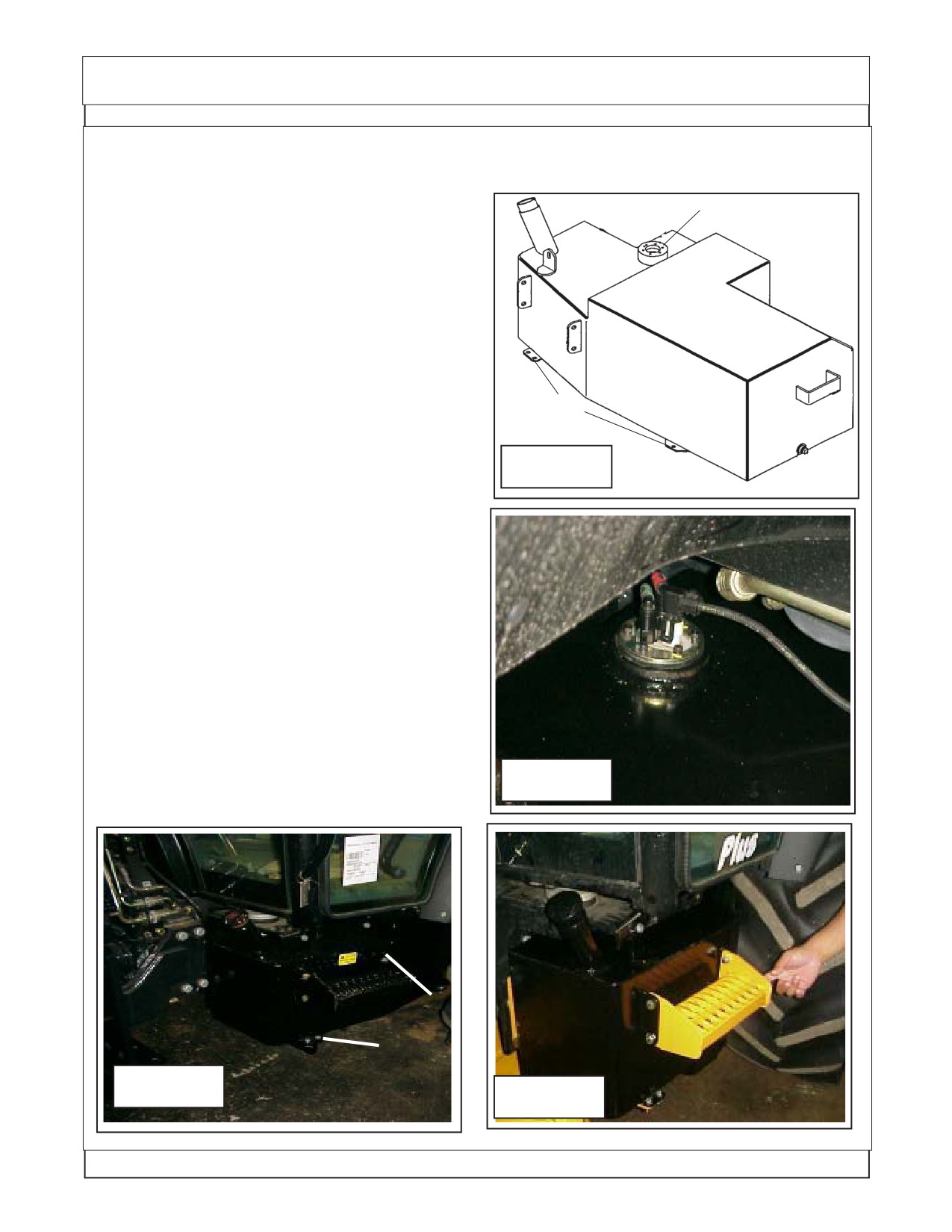
Install Pick Up Tube & Gauge Sending Unit in
new Tank. The Pickup gauge sending unit from the
factory tank will be installed into the new tank. This is
recommended to be done before mounting the new
Front
Pick Up Tube Unit
tank to the tractor (See Figure 13). The new tank will
have a fuel capacity of 51 gallons
5.
Install the new mount brackets to the tractor
frame. The tank mounting brackets will bolt to the
tractor the same as the factory brackets that were
removed. Make certain that the brackets are in-
stalled correctly, the front bracket will have 2 outer
Tank
holes (same as the tank see Figure 11 & 13). The
P/N 02982198
Mounting
rear bracket will have 1 hole in the outer end (same
Tabs
as the tank, See Figure 12 & 13)
Figure 13
6.
Install The new Fuel tank onto Tractor. The
Rear
new fuel tank with the gauge sending unit slide in on
top of the new mounting brackets with the fuel cap to
the front (See Figure 14). Connect lines to fuel pick
up connections, connect wiring to fuel gauge send-
ing unit. (See Figure 14)
7.
Bolt Tank to the Mounting Brackets. Bolt the
tank to the mounting brackets, there are two bolts in
the front bracket and one bolt in the rear bracket.
(See Figure 15)
8.
Install New replacement Step. The new Re-
placement step is a bolt on weldment that will bolt to
the new fuel tank with four bolts, note: below the
Figure 14
step is painted yellow for clarity only (See Figure
16).
Rear
Bracket
(1 Bolt)
Front
Bracket
Figure 15
(2 Bolts)
Figure 16
Maverick (NH TS-100A,115A ,125A/,35A Asy. Man) 01/05
Section 5 - 5
Frame Installation
Under Mount frame Asy:
1.
Before beginning any repairs on this section make certain the boom is extended outward to
full extend and laying on the floor. Before removing the Boom Pivot Pin support the boom with an
overhead hoist so as when Pie is removed boom can be lifted out of the way. NEVER REMOVE ANY
PINS OR BOLTS unless boom is supported at pivot end and head end is resting on the floor.
2.
The under mount frame asy is made up of the Turret, Center Section Frame Weldment,
Boom Mount, Swing Cylinders, Swing Cylinder Trunnion Mount, Turret Cylinder Link and Counter
Weight.
3.
The Turret Asy will be shipped assembled to the Boom mount with the hoses and cylinders
plus attaching hardware assembled to it.
4.
The Swing Cylinders have replaceable mounting bushing which can be replaced by
removing the bottom cover and trunnion mount weldment. The Cylinders can be dropped down
enough to replace the bushing. The replace the Trunnion Mount weldment. Also by removing the
cylinders the Turret Cylinder link can be removed.
5.
The Turret assembly has a large bearing assembly bolted to it and then bolted to the Boom
Mount. This Bearing CANNOT be removed (or replaced ) unless the Boom is disconnected from it
first. When disconnecting boom make certain the boom is supported as not to fall (See Step 1). The
Bolts retaining the turret to the bearing and the bolts connecting bearing to the Boom Mount MUST
be torqued to the required specification, This is very critical. See the Bolt Torque Chart in the
beginning of this manual.
6.
DO NOT remove any mount pins and/or bolts unless the components are supported properly
to prevent them from falling
7.
The Turret Bearing Assembly has 3 grease fittings, each 120° apart. All three of these grease
fittings must be greased because of the diameter of the bearing this to ensure an even distribution
of grease though out the diameter of the bearing assembly.
8.
If the hoses for the swing cylinders are disconnected or replaced make certain that they are
reconnected correctly as shown in this section (Swing Cylinder Hose Routing). If the hoses are not
connected correctly the swing will not function correctly.
Maverick (NH TS-100A,115A ,125A,135A Asy. Man) 01/05
Section 5 - 6
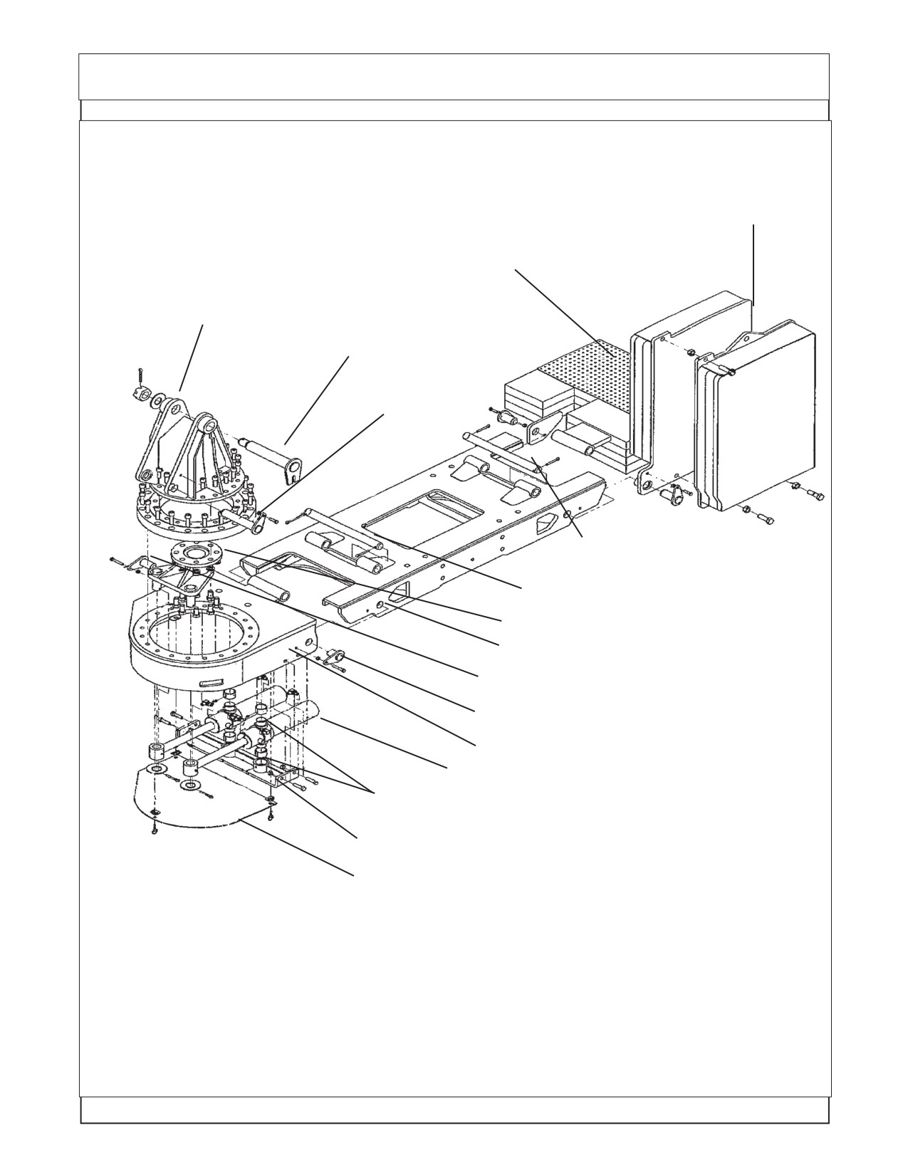
Frame Installation
Under Mount Frame Asy
30 ft model only
(24 & 30 ft are the same except for the LH weight)
LH Counter Weight
Turret Asy, Machined
Turret / Boom Mount Pin
Lift Cyl Pin
Weight Attaching Pin, Long Pin
Boom Mount Attaching Pin, Long Pin
Turret Cylinder Link
Center Section Frame Weldment
Boom Mount Attaching Pin, Medium Pin
Boom Mount Attaching Pin, Short Pin
Boom Mount, Machined
Swing Cylinders
Swing Cylinder Pivot Bushings
Swing Cylinder Trunnion Mount Weldment
Swing Cylinder Cover
Maverick (NH TS-100A,115A ,125A/,35A Asy. Man) 01/05
Section 5 - 7
Frame Installation
Frame Installation:
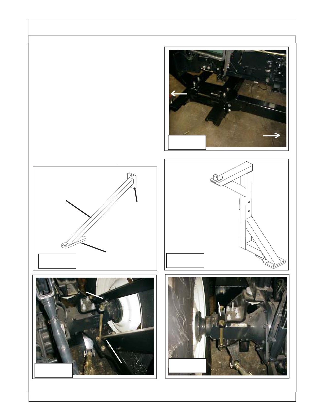
1.
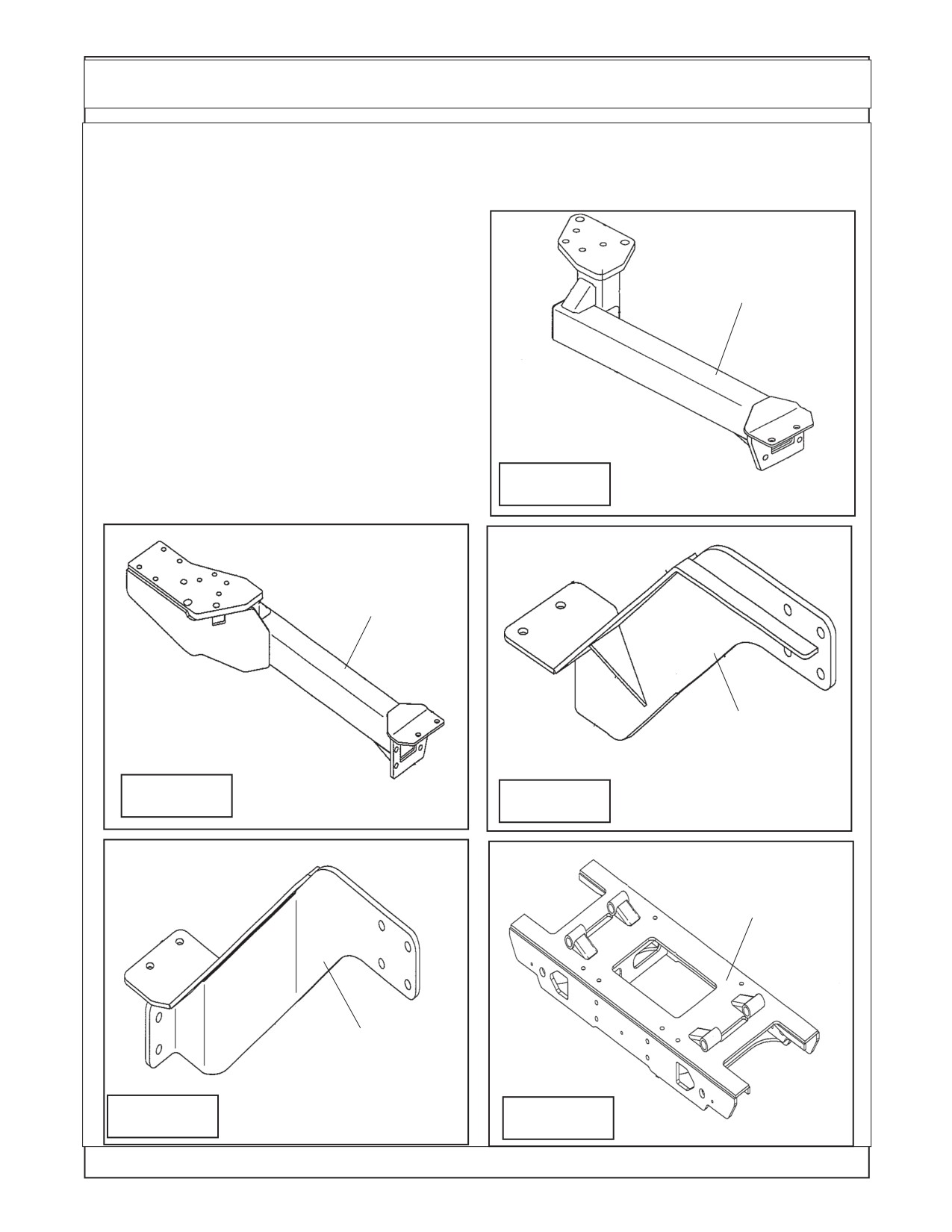
Frame Components. The frame will include
the rear axle mounts, a LH & RH Frame rail. Two
front frame mounts, a LH & RH. One center frame
LH Rear Frame
weldment. (See Figure 17, 18, 19, 20 & 21)
Mount Weldment
P/N 02982006
2.
Install Frame Components. The Frame
components will only fit one way. The Frame com-
ponents are a Bolt together assembly no welding
will be required. The Frame components will bolt
together and to the tractor using mostly 3/4" and/or
20 mm bolts. Each 3/4" & 20 mm bolt will use
hardened flat washers, one on the head side when
bolts go into the tractor castings. Two washers
used when bolts use a nut and go through the
Figure 17
frame. These hardened washers are important.
RH Rear Frame
Mount Weldment
P/N 02982005
RH Front Frame
Mount Weldment
P/N 02982015
Figure 18
Figure 19
Center Frame
Weldment
P/N 02981168
LH Front Frame
Mount Weldment
P/N 02982014
Figure 20
Figure 21
Maverick (NH TS-100A,115A ,125A,135A Asy. Man) 01/05
Section 5 - 8
Frame Installation
3.
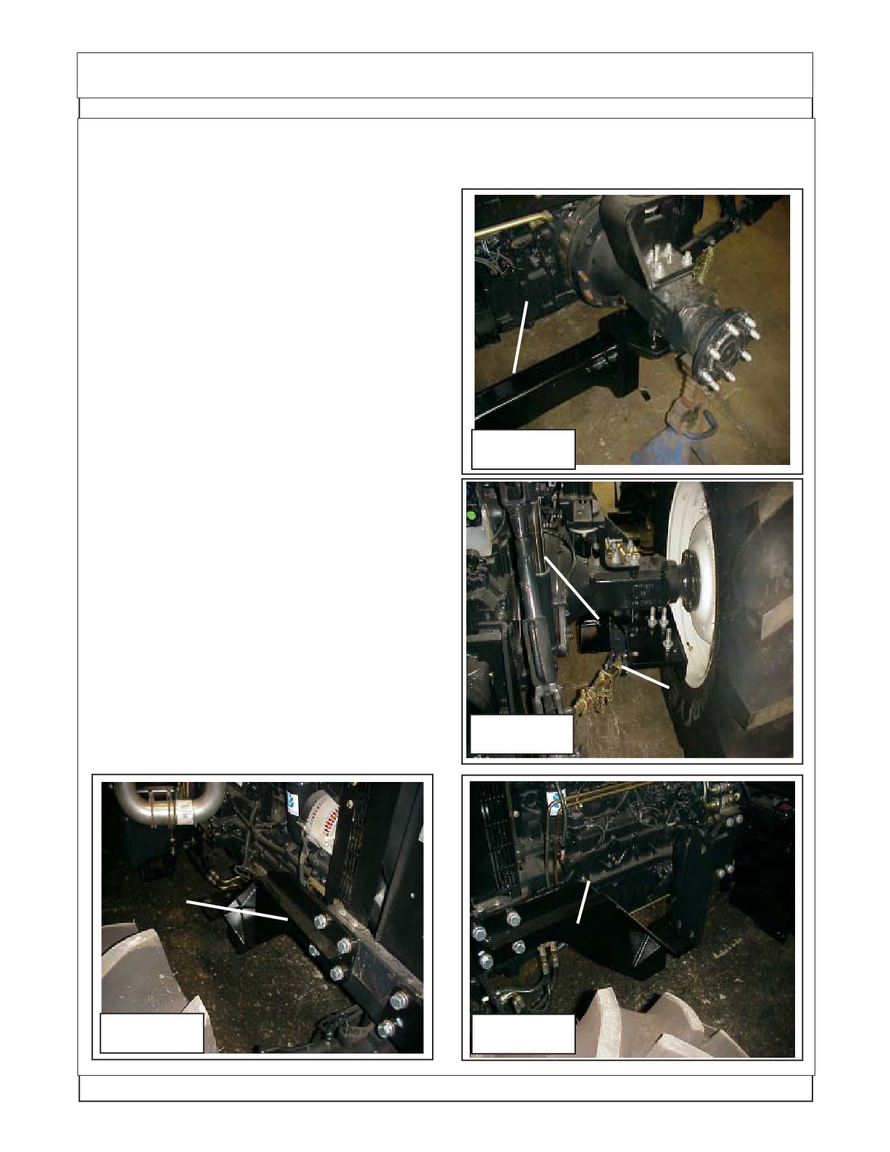
Install Rear Frame Mount Rails. Rear frame
rails consist of a LH & RH. We have started with the
Left Hand Rail. The three point lift stabilizer brackets
will need to be unbolted on both sides. In the illustra-
tion for the LH side we installed the frame with the
LH rear tire and wheel still removed, this was done
LH Rear Frame
for clarity not because the wheel needs to be re-
Mount Weldment
moved. Using a floor jack to lift the rail up under the
P/N 02982006
rear axle (Stabilizer brackets for three point have
been unbolted). Install the bolts up and into the three
point stabilizer bracket and the tractors rear axle
housing and snug the bolts down. Support the frame
rail with a jack stand (or leave the floor jack under it).
(See Figure 17 & 22).
The RH Rear Frame Rail will basically install
the same, bolts up under the tractor axle housing
with the three point stabilizer bolt back up under
Figure 22
frame rail (See Figure 18 & 23). The RH Rail looks
different at the rear because the boom rest will bolt
here later.
RH Rear Frame
Mount Weldment
4.
Install Front Frame Mount Rails. The Front
P/N 02982005
Frame mount rails will consist of a RH & LH (See
Figure 19, 20, 24 & 25) These will only fit one way as
they have a gusset reinforcement on one side that
will be showing to the outside when installed. These
can be lifted by the technician installing them. The
LH and RH will install the same way, Using 4 bolts
each that screw into tractor casting on the side of
the tractor (See Figure 24). Make certain that all 3/4"
3 Point Stabi-
and 20 mm bolts have hardened flatwashers on
lizer Bracket
them.
Figure 23
LH Front Frame
Mount Weldment
RH Front Frame
P/N 02982014
Mount Weldment
P/N 02982015
Figure 24
Figure 25
Maverick (NH TS-100A,115A ,125A/,35A Asy. Man) 01/05
Section 5 - 9
Frame Installation
5.
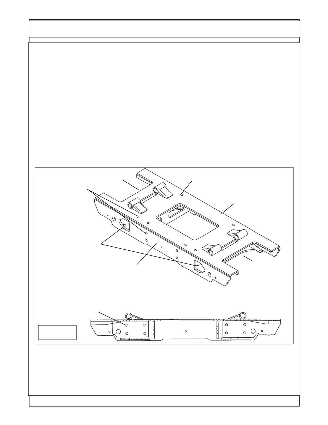
Install Center Frame Weldment. The Center Frame Weldment has a front and a back side (LH
& RH side). The Center frame must be installed with the two openings (See Figure 26) toward the front
of the tractor. These openings are to allow for the movement of the swing cylinders when moving the
boom to the boom rest position.
IMPORTANT NOTE: When bolting the center frame up to the front and rear frame mounting
rails the bolts on the RH turret side must have the bolts installed from the bottom with the bolt heads on
bottom under center under frame and the nuts on top (See Figure 27 showing nuts on top). The reason
the nuts must be on top is so the bolts will not hit the swing cylinders when the turret assembly has been
mounted. The Bolts that are used to mount center frame are not the same lentgh. The 8 bolts for the rear
fame bracts (bolts that face the rear of the tractor) will be 3/4" X 3-1/2" long. The other twelve bolts will be
3/4" X 2-1/4" long. All 20 Bolts that at are used to mount center frame MUST have hardened flat washers
install on both sides, one under Bolt Head and one under Nut (See Figure 26 & 27)
Using floor jacks (or Fork lift) position the center frame weldment up under the tractor (See Figure
27). The center frame weldment will bolt to the front and rear mounting rails on both sides. Make Certain
to use hardened flatwashers on all 3/4" and 20 mm bolts, when using nut on bolts it will need two
hardened washers, one on each side (See Figure 27) . Double check the frame mounting bolt tightness.
RH Side
Rear Top Mounting Holes use 3/4" X 2-1/
of Tractor
4" bolts in these 4 places
Front Mounting
Holes use 3/4" X
Rear of
2-1/4" bolts in
Tractor
these 8 places
Install with these
openings to front
of tractor
LH Side of
Front of
Tractor
Tractor
P/N 02981168 Center Section Under Mount Frame Wldmnt
Rear Mounting Holes use 3/4" X
3-1/2" bolts in these 8 places
Rear View
Figure 26
6.
Install Boom Rest Weldment. The boom rest weldment for the 24 foot boom and the 30 ft.
boom are not the same (See Figure 29). The boom rest weldment bolts to the RH Side on the Rear
Frame mount weldment behind the tractor axle weldment (See Figure 30). It is recommended that this
be installed using an overhead hoist and supported by the hoist until boom rest and support brace
(See Figure 28 & 30) are completely installed. The Boom Rest Support also serves as the top axle
strap for the RH Axle mount (See Figure 30).
Maverick (NH TS-100A,115A ,125A,135A Asy. Man) 01/05
Section 5 - 10
Frame Installation
7.
Install LH Axle Strap. The Axle Strap bolts
down over the top of the Axle (LH Side) and bolts run
Shown from LH
through the Rear Frame rails. The RH Side the axle
side of tractor
strap is part of the boom support brace weldment
and also bolts down over the axle with the bolts
through the rear frame rail (See Figure 30 & 31)
Front
Make certain that all the bolts mounting the
frame components and the boom rest are properly
torqued, see the bolt torque chart.
8.
Reinstall LH Rear Tire and Wheel. Reinstall
the LH rear Tire and Wheel now if it has not already
Rear
been done. Use a hoist to lift and secure the rear
tires is recommended as they are very heavy.
Figure 27
Boom Rest
Support Weldment
P/N 02982022
Boom Rest
(f/24 ft or 30 ft.. boom)
Weldment
P/N 02982314
Bolts to
(f/24 ft. boom)
boom rest
&
P/N 02982025
(f/ 30 ft. boom)
Bolts to top of
Figure 29
Figure 28
tractor axle
Boom Rest Support
LH side of tractor Upper
& Axle Strap
axle strap
Weldment
P/N 02980694
Figure 31
Boom Rest
Figure 30
Maverick (NH TS-100A,115A ,125A/,35A Asy. Man) 01/05
Section 5 - 11
Frame Installation
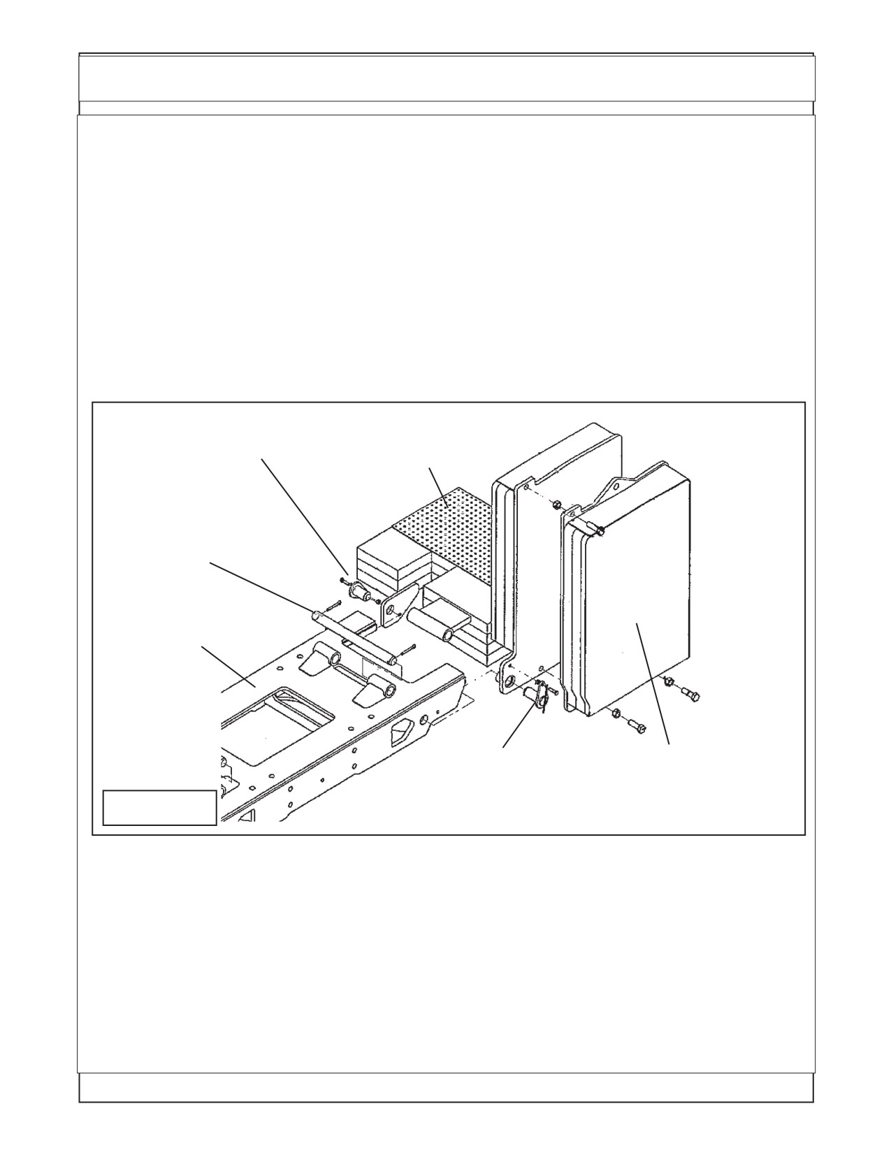
Counter Weight Installation 24 & 30 Foot Boom:
1. Counter Weight (CWT) Installation. The Counter weight (See Figure 1 ) mounts on the LH side Under
Frame Weldment. Its is retained with three pins, the long pin on top, the short pin at the rear and a short
pin at the front. Using a hoist or other sufficient lifting device align the weight with the frame. The Frame
for the weight will slide over the under frame until the upper long pin is aligned with the mounting tube of
the weight and the mounting tubes of the under frame. Install the long mounting pin. The front and rear
pin holes should be aligned, install the short pins front and rear. The short pins are retained using a nut
and bolt. The long pin uses two large cotter pins, install cotter pins and bend end of them to secure them.
(See Figure 32 , 33 & 34)
2. Additional Counter Weight (CWT) Installation: The 30 foot boom model has an additional bolt on weight
at the counter weight. This additional weight bolts to the weight weldment on the 30 foot model only (See
Figure 32)
Weight Attaching Pin,
LH Counter Weight 24 or
Short Pin Rear side
30 Foot Boom
Weight Mount
Attaching Pin,
Long Pin
Center Section
Under Frame
Weldment
Additional bolt on
Weight Attaching Pin,
Weight Used on
Short Pin front side
30 ft boom models
Figure 32
only
3. Wheel Counter Weight (CWT) Installation: The Wheel counter weight is in addition to the frame
mounted counter weight, they both must be used together, the 30 foot boom will have an additional frame
counted counter weight bolted on, (See Figure 32). All these weight are in addition to adding liquid weight
into the Left rear tire. The proper amount of counter weight is not complete until all these weight have been
installed.
Maverick (NH TS-100A,115A ,125A,135A Asy. Man) 01/05
Section 5 - 12
Frame Installation
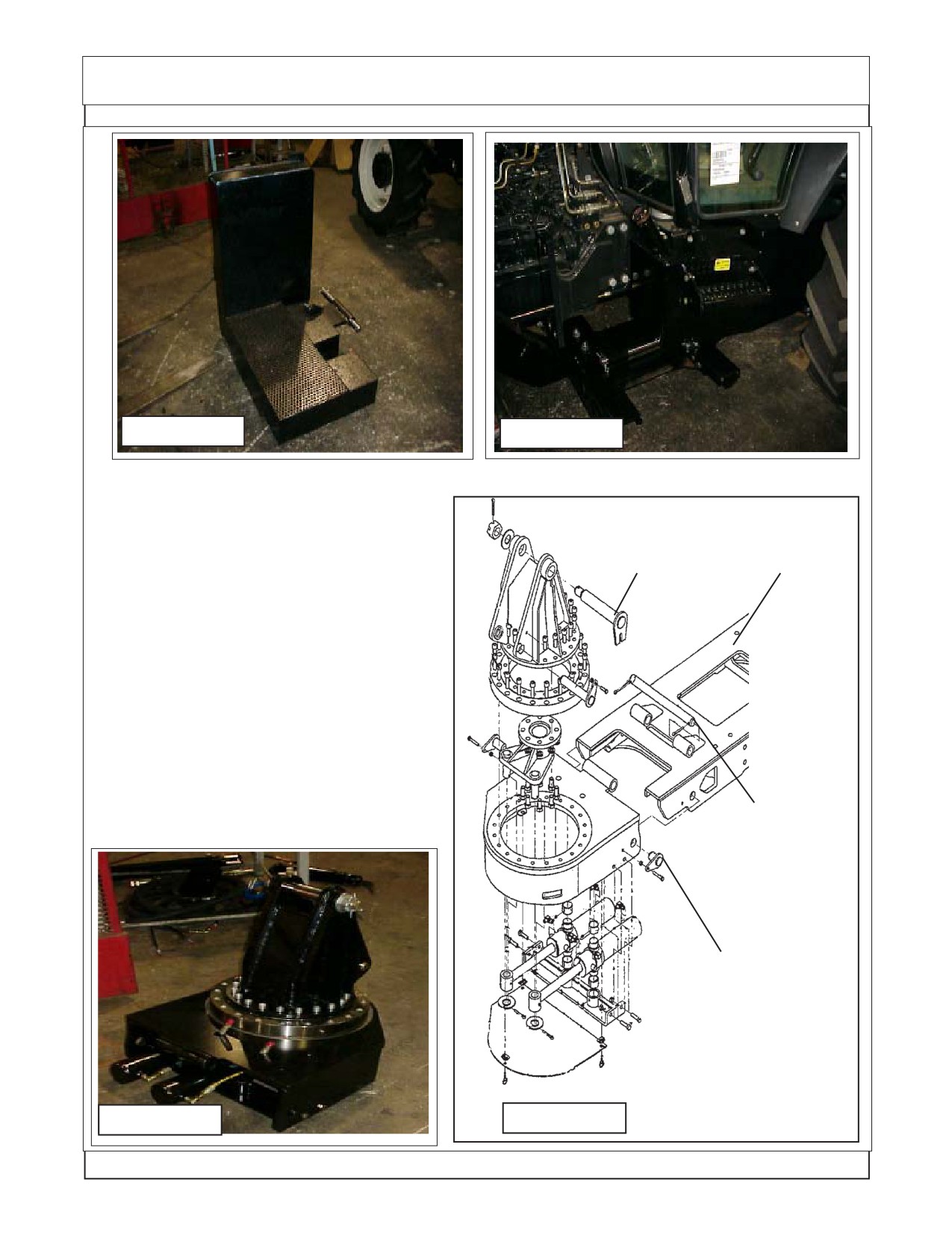
Figure 33
Figure 34
Turret Assembly Installation 24 & 30 Foot Boom:
1. Turret Assembly. Theturret assembly is
Turret Mount
Center Section
shipped assembled with the hydraulic swing cyl-
Under Frame
inders, hoses, pivot bearing assembly, boom
Attaching Pin,
Weldment
mount weldment and mounting pins installed
Long Pin
(See Figure 35 & 36).
2. Under Frame Weldment. The Under frame
weldment center section is designed for the turret
assembly to mount on the RH side. Remove the
one long mounting pin and the front and back
short mounting pins (See Figure 36 & 37). Check
to make certain the mounting bolts mounting the
center ubder frame weldment are installed with
the bolt heads unter frame weldment and nuts are
on top visible looking down, if they are in wrong the
swing cylinders will hit the bolts causing damge to
Turret Mount
cylinders and bolts. (See Figure 37)
Attaching Pin,
Long Pin
Turret Attach-
ing Pin, Short
Pin, one Front
side and one
rear side.
Figure 35
Figure 36
Maverick (NH TS-100A,115A ,125A/,35A Asy. Man) 01/05
Section 5 - 13
Frame Installation
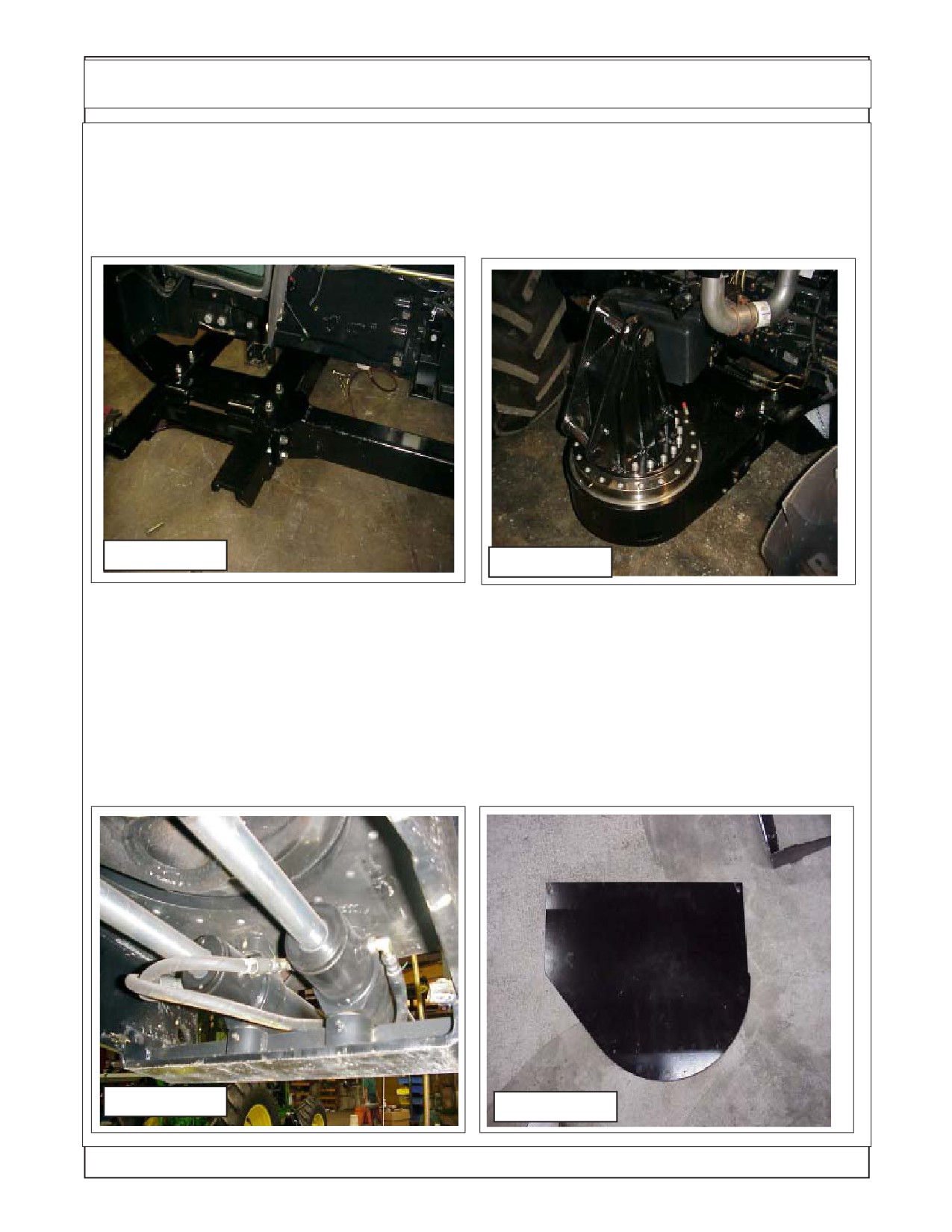
3. Turret Assembly Installation. Theturret assembly mounts on the RH side onto the center section
under frame (See Figure 36 & 37) . Using a hoist (or other lifting device) lower the turret assembly until
it is level with the underframe. Slide the turret assembly inward toward the under frame until the retaining
pin tube on under frame an turret assembly align. Installthe long upper retaining pin and then the two small
front and rear pins. The long upper pin is retained with two cotter pins that need to be bent over on the
ends. The short pins are retained with nuts and bolts (See Figure 36 & 38).
Figure 37
Figure 38
4. Turret Assembly Grease Fittings. The turret assembly has three grease fittings around the OD of
it. The grease fittings are 120° apart, this is to make certain that the bearing will be greased all the way
around because of the large diameter of the bearing. This bearing must be greased before unit is put into
service. It is easier to get to grease fittings now than after boom has been installed. On the under side
of the turret assembly are the grease fittings for the swing cylinder pivot mounts, these need to be
greased before operating the unit. Also there is a bolt on cover on the under side of turret that will be
installed (See Figure 40) at a later time. Greasing the cylinder pivots will need to be done before the cover
is installed (See Figure 39) and the boom swing stop will need to be adjusted, but this cannot be done
until a later time making it best to leave this cover of until then. After greasing components at assembly
of unit operator should consult the operators manual for maintenance requirements.
Figure 39
Figure 40
Maverick (NH TS-100A,115A ,125A,135A Asy. Man) 01/05
Section 5 - 14
Front Axle Stabilizer Installation - 30 FT Model (Standard)
Front Axle Stabilizer Kit Installation:
1.
Install Front Axle Stabilizer Kit (Kit P/N 02981895). The front axle stabilizer kit is standard on the
30 foot model. The front axle stabilizer kit will consist of all brackets and hardware to install to front RH
side of 4 wheel drive axle RH side of tractor frame
This kit is tied to the oil supply at the Lift Cylinder for
P/N 02983143
Engine side
the boom, the upper pressure supply hose (# 4 hose with
New front axle
blue plastic tie) is tee'd to the "B" port of valve for the lift
bracket (top)
cylinder and connected to the Base end of the stabilizer
cylinder. The lower Hose is connected to the rod end of the
Back side
cylinder and is connected to the tank return hose at the
tank. Install the cylinder with the rod end toward the axle
P/N 02983144
and the base end of cylinder up to the bracket (item 3)
New front axle
bolted to tractor frame. Number 4 hose with a blue plastic
bracket (bottom)
tie at the front side of tank (See Figure 41 through 48).
The Brackets bolt to the tractor axle and form a
RH Front
clamp around front axle housing (item 1 & 2). The Stabi-
lizer cylinder is charged only when the boom lift cylinder is
Tire side
activated and is controlled automatically with the boom lift
Figure 41
controls.
The three axle brackets are as follows
Item Part No
Qty Description
P/N 02982320 Cyl Sup-
port Weldment
(In-
1
02983143
1
Top Axle Bracket
cluded in Front Axle Sta-
2
02983144
1
Bottom Axle Bracket
bilizer Kit Only)
3
02982330
1
Stabilizer Support Bracket
4
02981316
1
Hydraulic Cylinder
See Mount Kit & Component ID section for Axle Stabilizer
complete component and hardware kit list.
2.
When installed correctly the three components
should be aligned as show (See Figure 44). The upper and
lower bracket should have the same gap between them in
front as in the back to make certain brackets are even.
Check the hose connections and all mounting bolts for the
Figure 42
axle stabilizer kit.
P/N 02981316 Cylinder Assembly
Upper Cyl
3456
(Included in Front Axle Stabilizer Kit Only)
23456
Mount Bolt
123456
123456
Lower Cyl
Pressure Hose End
2
123
Mount Bolt
3456
23456123456
2
123456
123
Return Hose End
1
12
34
12
234
123
Upper Clamp
Axle End
Mount Bolt
Support Bracket End
234
1234
123
Figure 44
Figure 43
Maverick (NH TS-100A,115A ,125A/,35A Asy. Man) 01/05
Section 5 - 15
NOTES
Maverick (NH TS-100A,115A ,125A,135A Asy. Man) 01/05
Section 5 - 16
Section 6
MAVERICK
New Holland Tractor
TS-100A,115A,125A,135A
Optional
RH Lexan Door
Installation
Section 6 - 1
Optional Lexan RH Door Kit Installation
New Holland "TS" Series Optional Door Kit No. 02980888
RH Lexan Door Kit. Option
P/N 02980888
Remove & Dis-Assembly of Factory Stock
Glass Door.
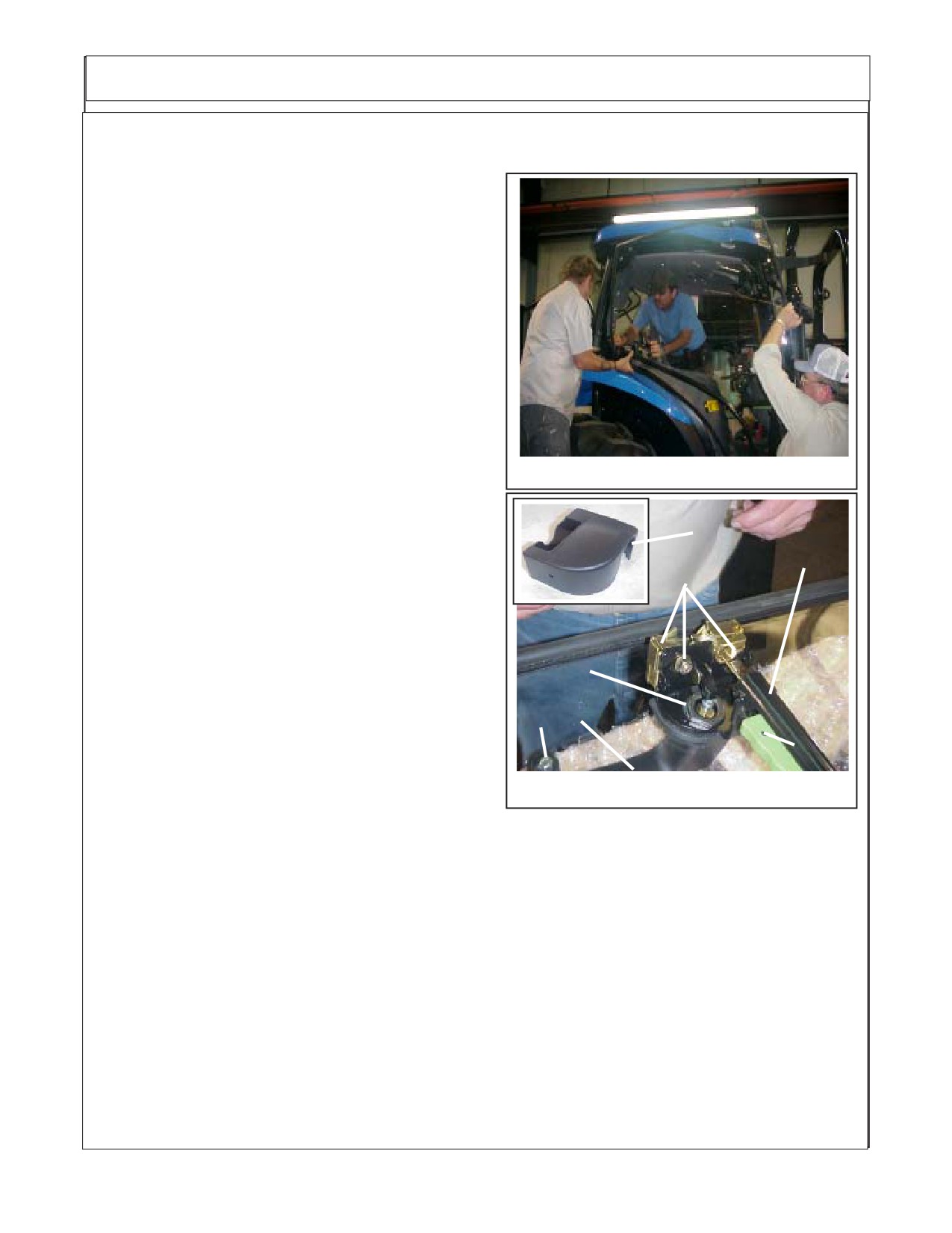
1.
To remove the factory door make certain
that you use enough help to remove it safely. It is
recommended to use three people as shown (see
figure 1) Use some type of container to hold all
removed components and hardware, some will be
reused & some will not. The Assembly procedure
and the dis-assembly procedure is the same except
in reverse. The RH Door is a mirror image of the LH
Door which can always be used for reference.
Figure 1
2.
Disconnect the gas shock (it is inside) from
the door pipe brace, disconnect it at the door end.
1
3.
With someone supporting the door at the
bottom and some one to hold the nuts inside loosen
7
2
the upper hinge bolts and the lower hinge bolts (See
figure 1) CAUTION! The lower hinge bolts also hold
the Pipe brace to the window, with these hinge bolts
removed DO NOT lift or hold window by using this
brace, it could put glass window under stress caus-
3
ing it to break. When Removing Bolts from hinges
make a note of the large rubber washer and the large
4
5
steel washer and there location as they will be reused
in the same location and order they are in. (See
6
Figure 1).
4.
Lay Removed door on a soft protected
Figure 2
surface for the disassembly of the latch and brace
components (See Figure 2). (Item 1) This is the plastic cover for the latch and will snap off. (Item
2) This is the Latch and retaining bolts, nuts & washers for the latch assembly, remove them. When
removing the latch you will need to lift and turn it in away that you can get the inside handle rod (connected
to item 5) pulled out of its hole in the latch not the handle item 5. (Item 3) Remove the upper retaining nut
and flat washer (this flat washer will not be reused) (Item 4) Remove the lower handle retaining bolt , there
will be rubber washer (that will not be reused) under the steel washer. (Item 5) The outer door handle can
be removed now, there will be rubber pad at the upper (larger portion) end between the glass and the
handle that will have a thin pipe type spacer in it. Also the lower handle mounting bolt will have a smaller
rubber pad with a metal insert in it that is between the glass and handle. (Item 6) This is the inner door
handle and WILL NOT be removed from the pipe brace weldment. (Item 7) This is the pipe brace weldment
and extends from latch / door handle to the lower hinge bolts. At the lower hinge bolts there will be a rubber
pad between glass and metal plate, this pad will be reused. (Item 8) This is the lower mount for the pipe
brace (See Figure 4 & 5 for fastener) and will be the last fastener removed, this fastener takes a special
tool to remove it. See your New Holland Dealer for instruction & Removal Tool.
Section 6 - 2
Optional Lexan RH Door Kit Installation
New Holland "TS" Series Optional Door Kit No. 02980888
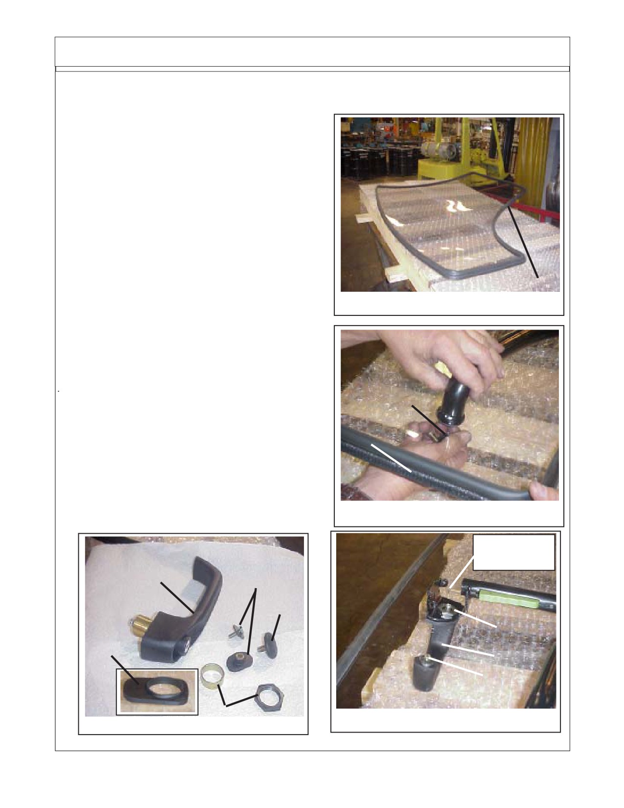
5.
Lay the New Lexan Door (P/N 02980803) on a
protected surface (here we used Bubble Wrap Packing
material). Install the push-on weather seal material (P/
N 02980889) with the soft rubber side up as shown. This
weather seal is designed to push-on with out adhesive,
but you can use adhesive if you wanted. Where the two
end meet an adhesive should be used to jion the two end.
Use an adhesve that is rubbery and dries to the touch.
The 3M Co. makes a good Black weather strip adhesive
that will work well for this (See Figure 3)
6.
Install the pipe brace on top of door.( Item 8)
This is the lower fastener
(See Figure 4 & 5) and will
need to be installed first, make certain to put the rubber
The two ends
washer back on fastener, install the fastener untill the
meet here
Figure
3
shoulder of the fastener is into the hole in the door. DO
NOT Tighten Fastener at this time.
7.
Install Outer Door Handle and fasteners. (Item
9) This is the outer door handle, before it can be installed
Item 10 must be modified (Item 10) This is the upper
mount of handle rubber pad. There is a shoulder on it that
must be cut off before it can be used, using a sharp knife
cut this shoulder off, The tube Spacer shown with item
8
3 goes through the hole of item 10 and then slide over
threads of item 9.
8.
Push the lower rubber (with steel insert in it)
into the hole of the door, holding the handle in place fron
the bottom start the bolt & washer item 4, there was a
rubber washer used under item 4 bolt. In some cases
it can not be reinstalled, check bolt engage ment to see
if it can be used.
Figure
4
Inner Latch
Actuater Rod
9
4
8
3
10
9
4
3
Figure 6
Figure 5
Section 6 - 3
Optional Lexan RH Door Kit Installation
New Holland "TS" Series Optional Door Kit No. 02980888
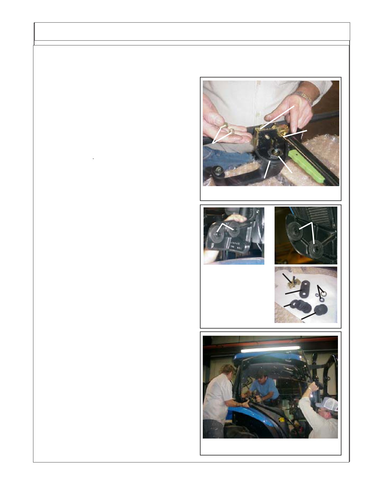
9.
Insert Handle into door from bottom, make
certain item 3 tube spacer is inserted through hole of
door and through hole of pipe brace, there is a rubber
pad to reinstall between pipe brace plate at upper
Latch
latch and door (See Figure 6) Install item 3 Nut onto
handle, Note when disassembled there was a large
flat washer here. The flat washer WILL NOT be used
Inner
in reassembly. Snug the item 3 nut but DO NOT
Latch
tighten.
Actuater
Latch Retaining
10.
Lifting the Latch and turning to the correct
Rod
Bolt, Washer &
angle slide the latch actuated rod through the hole on
Nut
the latch. Turn and lower latch in place. Using the
original Bolts, Washers and nuts bolt on the latch to
Inner Rubber Pad
3
pipe brace (See Figure 7). These can be tightened at
Figure 7
this time.
11.
Prepare the Door Hinges which are still on
Large Rubber
Large Rubber
tractor (See Figure 8) by making certain the round
Washers
Washers
rubber washers are in place, the ID of washer will
have the shoulder of the hinge sticking through it as
shown (See Large Rubber Washers Figure 8). The
lower hinge uses a two hole oblong rubber pad
between door and pipe brace.
Lower Hinge
Upper Hinge
12.
Install new door, make certain all rubber
pads are in place, Holding door push the lower hinge
1
up to door. Install the new 5/16" NC X 1-3/4" Gr. 5
5
Bolts P/N 00021900 from kit, Use the old small OD
structural flatwashers that were removed from origi-
2
nal door. The Top Hinge on the inside will have a
3
round rubber washer pad and a large round steel
washer. The lower hinge should have the oblong
Figure 8
4
rubber pad with two holes in it. Put the New 5/16" NC
locknuts with any washers that were remove form
original door. While supporting the door (see Figure
9) tighten the hinge mounting bolts, Do this slowly
and carefully making certain the shoulder oh hinge
goes through hole in door. DO NOT over tight these
bolts. Tighten the other fasteners on the door brace
and latch handle. If Door is not fitting right the door
striker bolt on the inner cab frame is adjustable by
loosing it up and moving it in or out as needed. USE
CAUTION when cleaning the Lexan door, DO NOT
use any cleaner that is harmful to plastic, Read all
directions for cleaner use befor using it, if using it for
the first time on the Lexan door, test it in a small out
of the way place. DO NOT use rough material such
Figure 9
as paper towels to clean Lexan Door.
Section 6 - 4
Section 7
MAVERICK
Standard Wheel Weight
&
Auxiliary Wheel Weight
Installation
New Holland Tractor
TS-115A,125A & 135A
Maverick (NH TS-100A,115A, 125A, 135A Asy. Man) 01/05
Section 7 - 1
Rear Wheel Counter Weight
Fill Left Rear Wheel with Liquid:
The Left Rear Wheel must be filled with liquid. Alamo Industrial recommends a Calcium
Chloride Water Mixture. The recommended Ratio of a 30 / 70 mix (30% Calcium Chloride and 70%
Water), this mixture will add weight at about 10.5 lbs per gallon. Follow the Mixture procedures
furnished by the Manufactured of the Brand of Calcium Chloride that you are using. It is also
recommended that a trained person installs the calcium Chloride. Calcium Chloride must be added
in addition to the Steel Wheel Weight and the Counter Weight that hangs on the Left Side. It is Not
recommended to use straight Water in the Wheel as this would not provide protection against freezing.
A 30/70 Calcium Chloride Water mixture provides antifreeze to approx -50 deg. F. below 0.
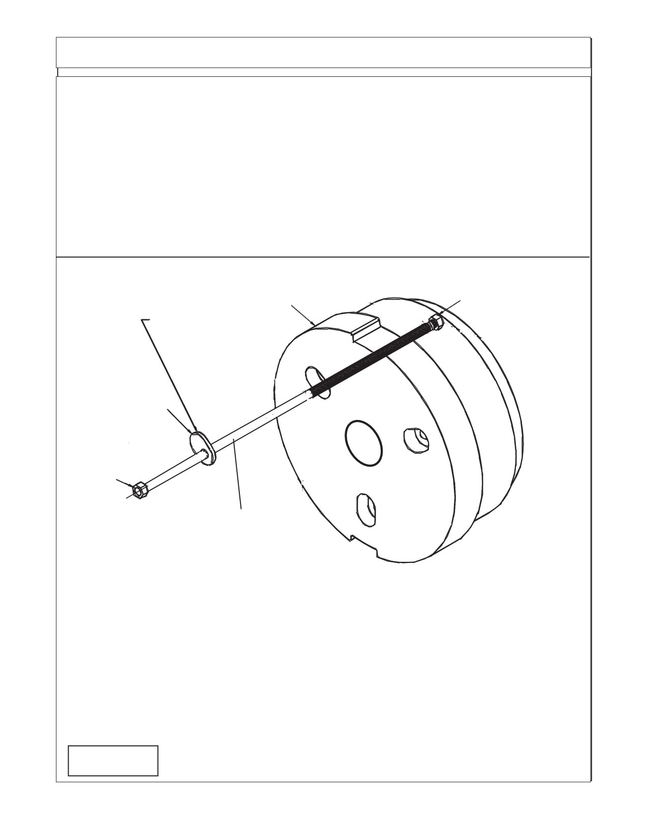
Rotate Washer to Match Bolt
Circle dia. and Washer fits into
4
3
Wheel Weight Slot.
2
1
Bolt is shown extra long in
drawing for illustration only
Item Part No.
Qty Description
1
02979603
3
Hex Head Bolt, 7/8" NC X 16"
2
02971569
3
Wheel Weight Washer, Special
3
02970758
1
Wheel Weight Casting, 1400 lbs.
4
5JRC1490
3
Locknut, Top Lock 7/8" NC
Note: some Older Units used a All Thread Rod with Hex Nuts Lock Nuts, with Flat Washer
and Lock washer. This was replaced with the Bolt Type shown above. These Bolt and Nut
combinations will replace the old All Thread type.
Figure 1
Maverick (NH TS-100A,115A, 125A, 135A Asy. Man) 01/05
Section 7 - 2
Rear Wheel Counter Weight
Installing Wheel Weight
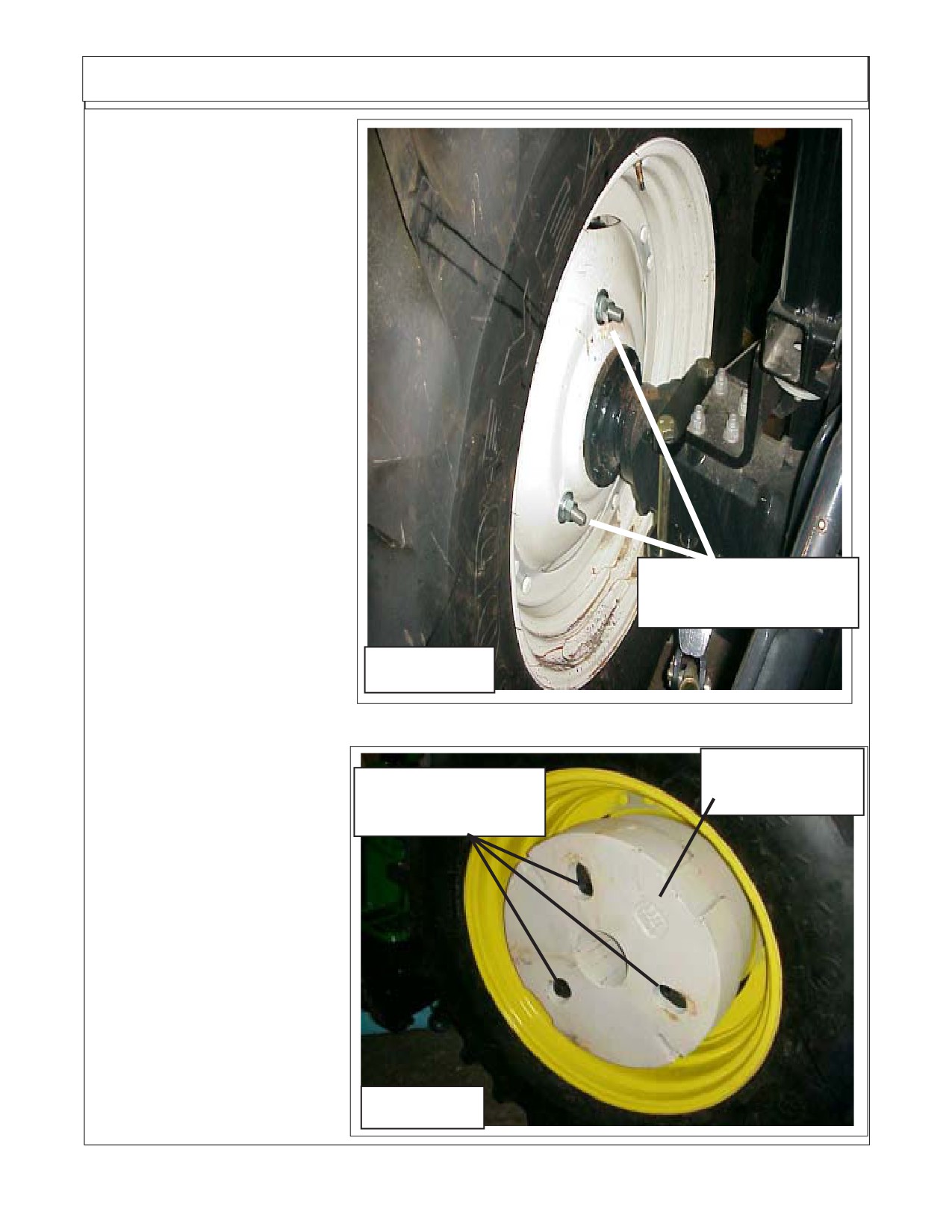
1.
This Wheel Weight is 1400
lbs. Always use caution when
working with it.
2.
Locate the three Holes in
LH Rear Wheel. Make sure these
holes are 15/16" dia. if not, they
must be reamed out.
3.
Lift Left Rear Tractor
Wheel till it just clears the ground.
This will allow the Wheel to be
rotated when aligning mounting
holes for Weight.
4.
Using a forklift, lift Wheel
Weight into Wheel. When Wheel
Weight is centered in Wheel Se-
cure Forklift and Set Parking Brake
on Forklift. Insert one of the three
bolts through Weight and Wheel
Wheel Weight Mntg
(Rotate Wheel to align holes if
Locknuts
needed). Install a Hex Lock Nut on
inside. Insert the other two Bolts
through Weight and Wheel and
Figure 2
start the other two Locknuts. Do
not tighten yet. (See Figure 2)
5.
Looking at the outside
make sure the three special Wash-
Wheel Weight
ers (Figure 1 Item 2) are aligned
1400 lbs.
with the Slots in the Wheel Weight.
Special Washers
Tighten the three Bolts now. You
Part # 02971569
will need an assistant to hold the
other Side while you are tightening
the Bolts. While tightening Bolts,
check to make sure the three spe-
cial washers are seated correctly.
If these Bolts are tightened and
washer are not seated into the
recess on Wheel Weight, dam-
age will occur. (See Figure 3)
6.
Remove forklift away from
Wheel and Weight. Recheck tight-
ness of Wheel Weight retaining
Bolts. Bolts should torque to 500
Figure 3
ft. lbs.
Maverick (NH TS-100A,115A, 125A, 135A Asy. Man) 01/05
Section 7 - 3
Auxiliary Rear Wheel Counter Weight
Installing Auxiliary Wheel Weight Kit.
1.
The Auxiliary Wheel Weight is made up of three steel plates and mounting hardware. Each
Auxiliary Weight weighs approx 136 lbs. When all three are installed on the existing 1400 lb. weight it
will increase the wheel weight by 408 lbs. This makes the total bolt on wheel weights equal 1800 lbs.
This will not include the amount of weight to the tire from the installed liquid which, will vary with the size
of the tire and the liquid that is added.
Auxiliary. Wheel Weight Kit No. 02976671
Qty Part No.
Description
2
00012200
Lockwasher, 7/8"
2
00012300
Nut, 7/8" NC
2
00760266
Bolt, 7/8"-NC X 5-1/2 GR8
3
02976644
Auxiliary Wheel Weight Plate, 136 lbs Each
2.
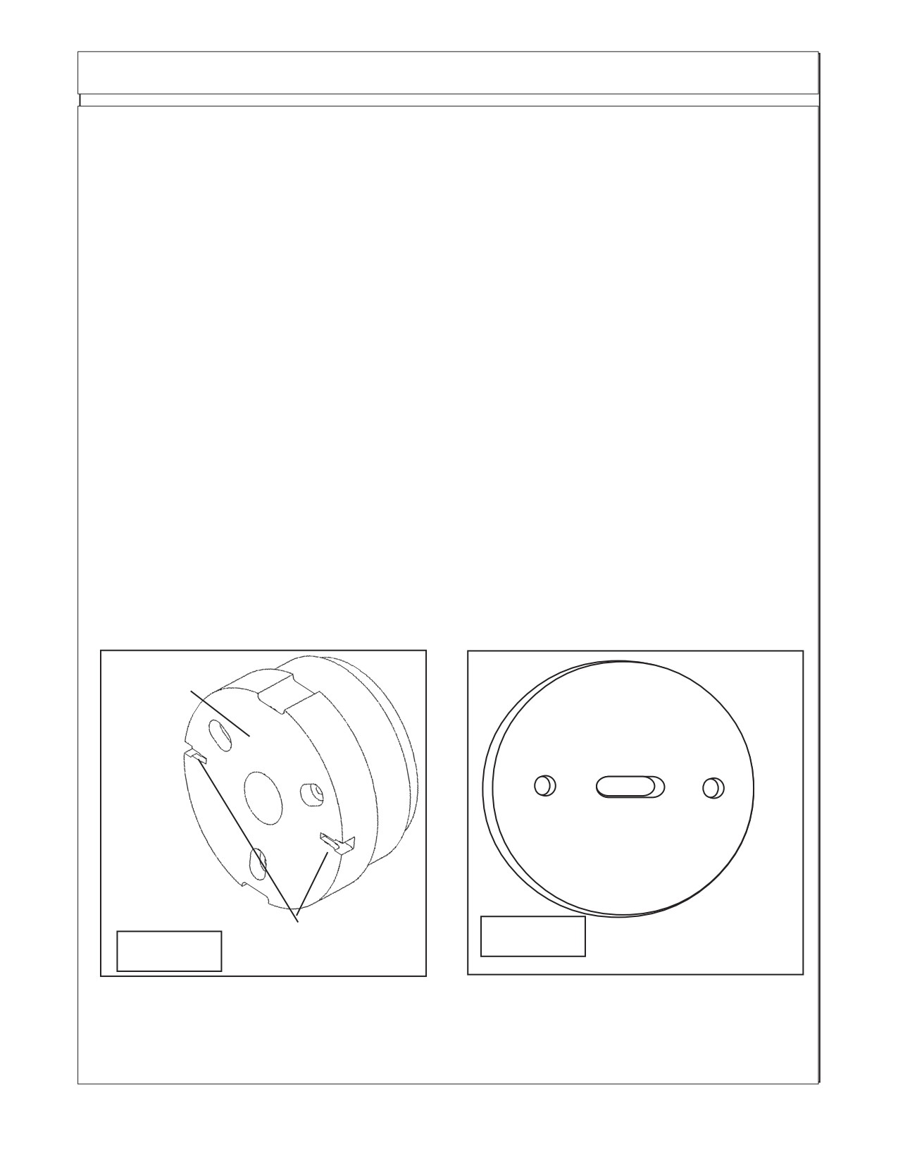
Install Auxiliary Wheel Weights. The Auxiliary Wheel Weight bolt to the larger 1400 lb. wheel
weight. There are two slots in the large weight that the 7/8" bolt heads will slide into. It is recommended
that the tractor wheel is in position so these two slots has one facing front and one to the rear. Slide the
two 7/8" bolts into the slots, the slots will prevent the heads of the bolts from turning. The Bolts in the
large wheel weight will have to be aligned to the proper distance apart, to match the distance of the holes
in the auxiliary weights. Slide the auxiliary weight over the two bolts, do this with all three weight for this
kit. Install the lockwashers and hex nuts. Tighten the bolts to required tightness. See bolt torque charts
in tractor preparation section.
Wheel Weight
P/N 02970758
Auxillary Weight
Figure 5
Figure 4
Attaching Stots
Maverick (NH TS-100A,115A, 125A, 135A Asy. Man) 01/05
Section 7 - 4
Section 8
MAVERICK
New Holland Tractor
TS-100A,115A,125A & 135A
Joystick - Wire Harness
& Valve Installation
Maverick (NH TS-100A,115A, 125A, 135A Asy. Man) 01/05
Section 8 - 1
Joystick / Electrical Mounting
Installing Wiring Harness and Joystick:
1.
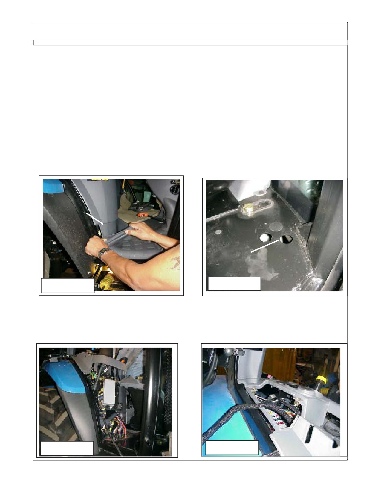
Preparing Tractor Floor Mat. First thing to do is remove the Battery Cables from Battery, Do
Not perform any work on Tractor or Boom Electronics unless this has been done. Raise the Floor Mat
up on the RH Side by the RH Door, You will need to fold it back approx. 12 to 14 inches (See Figure 1
& 2). DO NOT Tear or Cut any Holes in Rubber Floor Mat, as it will NOT be required.
You may find a rubber plug or you may have to cut a hole with a hole saw, this will have to be decided
during installation. If you need to cut a hole, check the under side of cab for any obstruction or any
component that might be damaged before you cut the hole. The hole is going to have to be oblong in
order for the plug to go through it. Measure Wire Harness plug Coded G1 to determine the size hole.
In Figure 2 below the tractor had two holes from the tractor manufacturer, technician removed the
rubber plugs and cut the space between the two holes to open it into one oblong hole. Check to make
certain the installation will not interfere with the operators normal functions.
(See Figure 1 & 2). Floor
mat can be reinstalled by over wire harness with out cutting any holes in floor mat..
Pull Floor Mat
loose here
Cut Hole in flor of
cab if not one
already in it.
FIGURE 2
FIGURE 1
2.
Remove Tractor RH Side Panel. Remove the side panel on the RH side of the cab so the wire
harness can be run down through and under top panel and will be covered when the panel is put back
on (See Figure 3). Isert the end of the interior wire harness with the pug coded G1 down into the panel
from top and out bottom of panel (See Figure 3 & 4).
FIGURE 4
FIGURE 3
Maverick (NH TS-100A,115A , 125A, 135A Asy. Man) 01/05
Section 8 - 2
Joystick / Electrical Mounting
Locating Joystick and electrical components:
1.
Joystick Assembly with Resister Harness. The joystick has the resister wire harness
attached to it when you received the joystick.
2.
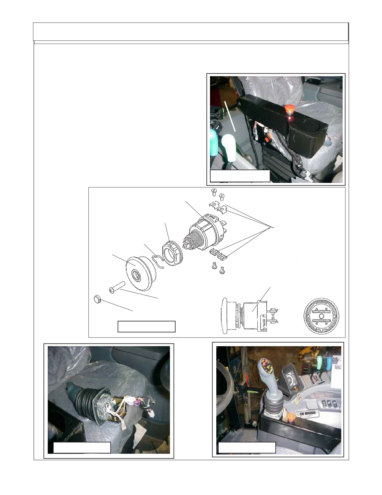
Emergency Stop Switch. The emergency Stop (E-Stop) Switch will be sent with the knob and
mounting nuts installed onto it. These will need to be removed when mounting switch.
3.
Replacement Seat Arm Rest. The Tractor seats Rh arm rest will be replaced with a fabricated
one to mount E-Stop Switch and Joystick.
4.
Wire Harness. The Wire harness is in two piece, The interior harness inside the cab and the
exterior harness connecting to the interior harness and running outside the cab to the pump and tank
area at the front of the tractor.
5.
Wire Harness through Floor of Tractor Cab. Some tractors may have a hole all ready through
the floor of the cab on the RH side. Lift Floor mat and check, if no hole (possible with rubber plug in it)
a hole will need to be cut with a hole saw. If cutting holes in floor of cab always check under side of floor
to make certain there are no components that will be hit and damaged by saw. DO NOT use a torch to
cut holes in cab floor.
6.
Access Panels of Tractor interior. Panels in the cab will need to be loosened and/or removed
to gain access to connections and/or mounting of components. Do not remove any panels until
instructed to do so.
Installing Seat Replacement Arm
Rest:
1.
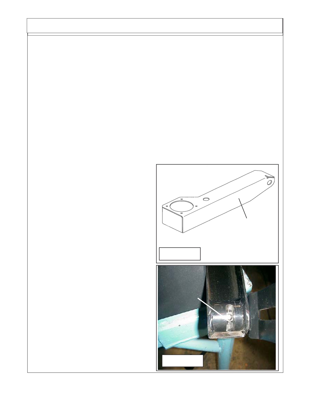
Replace RH Factory Arm Rest. The fac-
tory seat RH arm rest will be replaced with a
weldment designed to serve as the armrest and
mount for the emergency stop switch and the
joystick assembly (See Figure 5, 6 & 7). Unbolt the
Arm Rest Weldment
factory arm rest and bolt on the replacement arm
P/N 02981415
rest. The Arem rest is retained using the same type
method as thr factory arm rest, this is what allows
the arm rest to be raised up and down (See Figure
FIGURE 5
6) See the bottom of the welded replacement arm
rest. It may be required to use a die grinder in slotted
hole th help with alignment of retaining bolt. (See
Figure 6).
Under Side of
2.
Install Emergency Stop Switch. The emer-
Welded Arm
gency Stop (E-Stop) Switch mounts into the arm
Rest with
rest in the smaller of the two holes. The Knob and
Slotted Hole
mounting nut will need to be removed and the
switch installed from the bottom of the arm rest.
Replace mounting nut and knob (See Figure 5 , 7 &
8)
3.
Locate Joystick Assembly. The joystick
assembly has a flange around the bottom, it uses 4
screws to mount joystick to the arm rest. Lower the
wiring of joystick down through hole in arm rest.
Make certain the three plugs are in the hole and not
FIGURE 6
being pinched. (See Figure 9 & 12).
Maverick (NH TS-100A,115A, 125A, 135A Asy. Man) 01/05
Section 8 - 3
Joystick / Electrical Mounting
Resistor Harness
J1
P/N 02981990 Is
Wire Harness Side
7
8
9
attached to the
4
5
6
Joystick when it
1
2
3
is recieved.
Pin Numbers &
Locations
6
3
9
7
8
4
1
5
2
PCB Assembly
P4-1
P4-3
P4-2
P2-2
P3-2
P3-1
P2-1
P3-3
P2-3
Pin Numbers &
Locations
Joystick Side
Z AXIS
Y AXIS
X AXIS
4
3
2
1
4
3
2
1
4
3
2
1
FIGURE 7
P4
P2
P3
Maverick (NH TS-100A,115A , 125A, 135A Asy. Man) 01/05
Section 8 - 4
Joystick / Electrical Mounting
4.
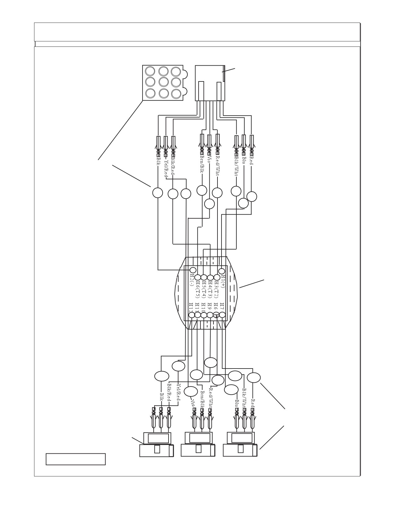
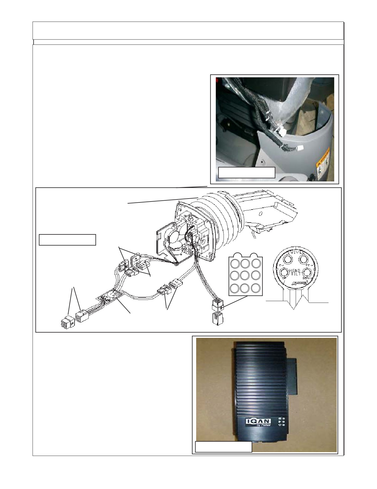
Resister Harness to Joystick. The Joystick will be shipped with the resister Harness
connected to it as an assembly. (See Figure 7 & 8) The Interior wire harness plug has 2 connectors
on it A 9 Pin Connector (labeled J1) and a 6 Pin Connector (labeled P1) . These two connections will
plug into the interior wire harness with the same code
when the interior harness is installed. (See Figure 7 &
Rear
8). The Interior harness is run under the RH side Panel
Panel
and along the rear panel. You will need to cut a notch in
the rear panel to allow the harness to pass between the
two panels where they meet near the bottom.
5.
Interior Wire Harness. The interior wire har-
ness has all the connections needed to connect interior
components. The RH side interior panel of cab will need
to be loosened and/ or removed, this allows mounting of
the XS module (See Figure 6 & Next pages for wiring
schematics) continued in step 6
FIGURE 7A
Switch
Switch Mounting Nut
Wire Fasteners (4)
Depth Control Clip
Knob
Switch Asy Complete
Knob Retaining
Screw
Knob Plug
FIGURE 8
FIGURE 9
FIGURE 10
Maverick (NH TS-100A,115A, 125A, 135A Asy. Man) 01/05
Section 8 - 5
Joystick / Electrical Mounting
6.
Interior Wire Harness (continued). The interior wire harness schematic (See Figure 11 & 12)
shows the wire harness as it is run through the cab. The XS Module will need to be mounted inside the
cab, the best place is behind the RH side panel (See Figure 6, 9 & 12). The wire harness will need it be
put under this panel, also with the connectors in the
appropriate place to connect with the interior components.
The harness to the joys stick will need to be run along the
panel at the back of the cab. CAUTION: The Harness has
two wires that run under the floor mat, the positive
wire MUST connect to the ignition key switch of the
tractor for a power source. DO NOT Connect the
positive wire anywhere else (See Step 9 & Figure 14
wire CC1).. The plug (G1) will need to run through the floor
to the exterior of the cab, it will connect to the plug (G2) of
the exterior harness. (See figure 11, 12, 13 & 14). Secure
wires under arm rest.
FIGURE 11
Joystick P/N 02981347
with Resister Harness
FIGURE 12
P3
To Activate Trigger Push In
3
6
9
P2
2
5
8
J1
1
4
7
P-1
P4
PCB
7.
XS Module P/N 02981533. The XS module
(See Figure 13) mounts in side the tractor cab
behind the right hand side panel (See Figure 13 &
14). The Connections (Three Separate Pugs, Can 1,
Can 2 & D) will be inside the side panel after it is
reinstalled and will not be visible unless you remove
the side panel (See Figure 14 , 16, 17 & 18 ). The XS
Module does not have a mount bracket, it will need to
be mounted by the assembly technician inside
panel where it will be out of the way, not interfere with
any tractor components and be secured. It can be
tied in or bolted. The Only Plugs protruding from
XS Module
behind RH Interior panel shoud be the plugs for the
display control box (See Figure 14, 16, 17 & 18).
FIGURE
13
P/N 02981533
Maverick (NH TS-100A,115A , 125A, 135A Asy. Man) 01/05
Section 8 - 6
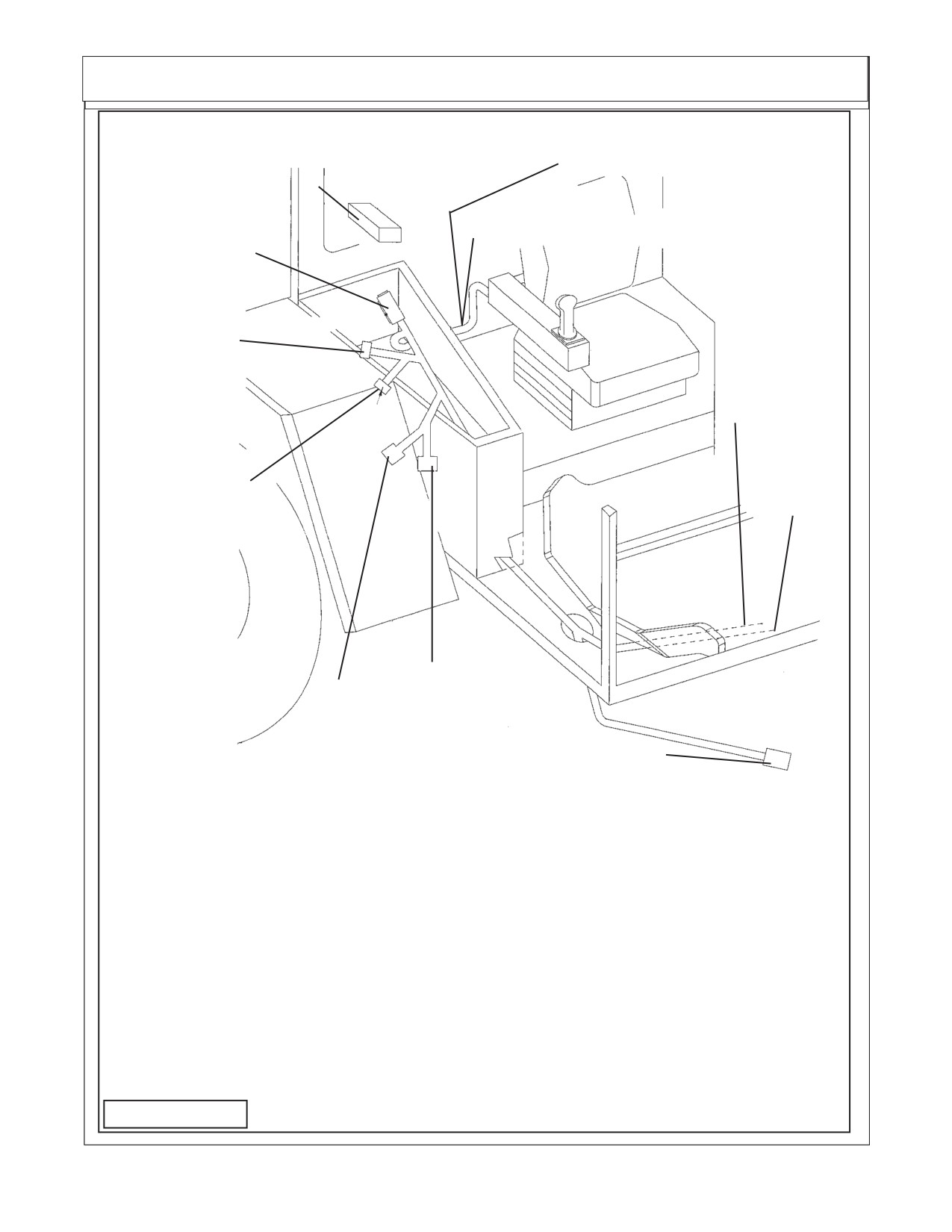
Interior Wire Harness Schematic P/N 02981375B
Remove console cover, tie strap
J1 Joystick Connection (9 Pin)
XS Module P/N 02981533 inside
console
P1 Joystick Connection (6 Pin)
D ( XS Module
Connector)
Can 1 ( XS
Module
Connector)
CC1 +Pos.
Key Switch
Connection
CC2 - Neg.
Can 2 ( XS
Chasis
Module
Ground
Connector)
X1 ( Control
K3 ( Control Box Display
Box Display
Connection
Connection
G1 (Connects to G2 Plug
of Exterior Wire Harness)
Code Connection
Can 1
XS Module Can1 Connection (2 of 3 Connections)
Can 2
XS Module Can 2 Connection (3 of 3 Connections)
CC1
+ Positive Key Switch Connection (MUST Connect to key switch wire)
CC2
- Negative Chasis Ground
D
XS Moudule C1 Connection (1 of 3 Connections)
G1
Exterior Harness G2 Plug (coonnects Interior & exterior Harness)
J1
Joystick Resister Harness (9 Pin Plug)
K3
Control Box Display Connection (1 of 2 Connections)
M1
E-Stop Switch (use A or B of Switch)
M2
E-Stop Switch (use A or B of Switch)
X1
Control Box Display Connection (2 of 2 Connections
FIGURE 14
Maverick (NH TS-100A,115A, 125A, 135A Asy. Man) 01/05
Section 8 - 7
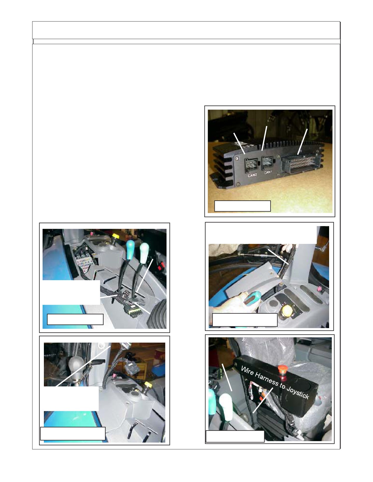
Joystick / Electrical Mounting
8.
Wire Exterior & Interior Harness Schematic. The wire harness schematics and instructions
will need to be used together to install the wire harness. The interior Harness and the exterior harness
will connect together with one plug connection. Figure 14, 16,17, 18 & 19) pertain to the interior harness,
Plugs have codes on them to identify where they connect, the connections will have codes on them to
identify where the connection goes. The code on the plug and the code on the connection may not be the
same, see the code connection listings in the illustrations to identify the connection location.
9.
Plugs for Display Control Box. The wire plugs for
Can1
Can2
C1
the display control box will come up through the small
cover on top of the right hand side panel (See Figure 16,
17, 18 & 19). When the small cover is replaced the plugs
and wires need to be moved to the back of the panel near
the RH rear cab post (See Figure 17 & 18). Cut a notch in
the panel at the rear so the cover will fit down around the
wire harness plugs (See Figure 17 & 18). Also the rear
XS Module
tractor panel will need a notch cut in it to allow the wire
harness to be installed between the side and rear panel.
P/N 02981533
Cut this notch near the bottom of the rear panel (See
Figure 19)
FIGURE 15
Cut Notch in Small cover panel to
allow harness to fit through
K3
Display Control
Box Connections
X1
FIGURE 16
FIGURE 17
Rear
Panel
Display Control
Box Connections
FIGURE 18
FIGURE 19
Maverick (NH TS-100A,115A , 125A, 135A Asy. Man) 01/05
Section 8 - 8
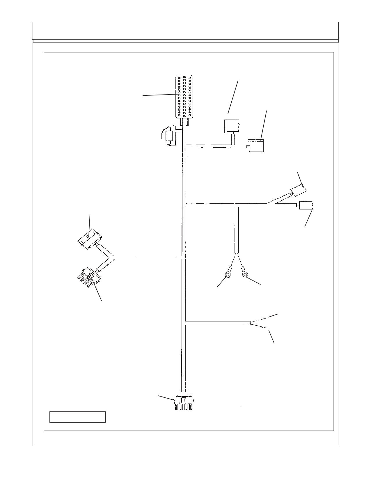
Interior Wire Harness Schematic P/N 02981375B
CAN 1 XS
MODULE
CAN 2
D
XS MODULE
NOTE: See Figure 11 for
J2
listing of Code Locations
K3
P1
M1
M2
X1
CC1 (Must
connect to
Key switch
wire)
CC2
G1
FIGURE 20
Maverick (NH TS-100A,115A, 125A, 135A Asy. Man) 01/05
Section 8 - 9
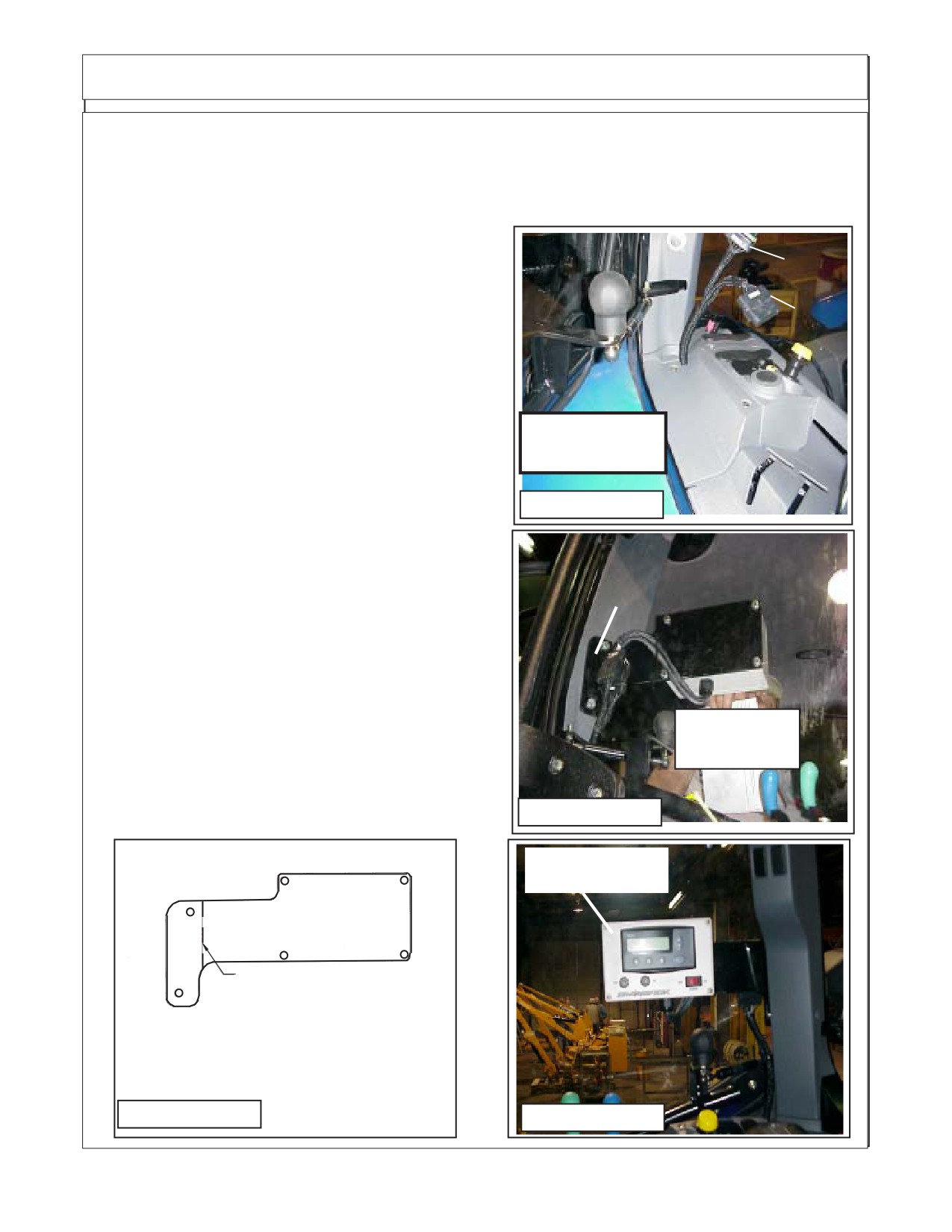
Interior XS Module & Display Control Box
9.
Connect Wires to Key Switch. There are two wires on the interior Harness that connects to the
key switch (Wires CC1 and CC2) these need to be routed under floor mat and in behind dash panels.
CAUTION:The positeve wire (CCI) MUST be connected to the wire from the key ignition switch
of tractor for an electrical power supply. DO NOT connect the power supply wire (CC1) to any
other power supply as it could cause interference with the electronic components due to a
power surge
10.
Tractor RH Side Panel reinstalled. When the
K3
tractor side panel is reinstalled the plugs (2 Plugs K3 &
X1) for the Display control box will be sticking up out from
X1
be hind the panel (See Figure 21), Run the wiring harness
in from behind panel, use caution to not let wire harness
interfere with or be in a position to damage or be damaged
by other tractor components behind panel.
11.
Install Display Control Box Mount Bracket. The
Display Control
display mount control box mount to the Rh rear cab post
Box Connections
(See Figure 22 & 23) . There are two plastic plugs in the
plastic cover over cab post. Remove these two plug to
FIGURE 21
expose two 10 mm bolt holes in cab post. Position the
mounting bracket with the bent end at the post and using
P/N 02982324 Mount
the 10 mm bolts furnished bolt the bracket to the post.
Plate - (Iqan) Display
Control Box Mount
12.
Install Display Control Box. The display control
box will bolt to the mount plate P/N 02982324 that is
mounted to the RH Rear Cab corner post (See Figure 22,
23 & 24). There is a wire setion on disply control box that
will pug into the two plugs on the interior harness plug KS
& X1 (See Figure 21 & 22)
The display control box cannot be tested until the interior
Cab RH Rear
and exterior wiring harness installation has been com-
Corner Post
pleted and all the other installations of unit have been
done. DO NOT reconnect battery cables at this time, the
electrical wiring is NOT done.
FIGURE 22
Display
Control Box
Bend Upward 60° Here
P/N 02982324 Mount
Plate - (Iqan) Display
Control Box Mount
FIGURE 23
FIGURE 24
Maverick (NH TS-100A,115A , 125A, 135A Asy. Man) 01/05
Section 8 - 10
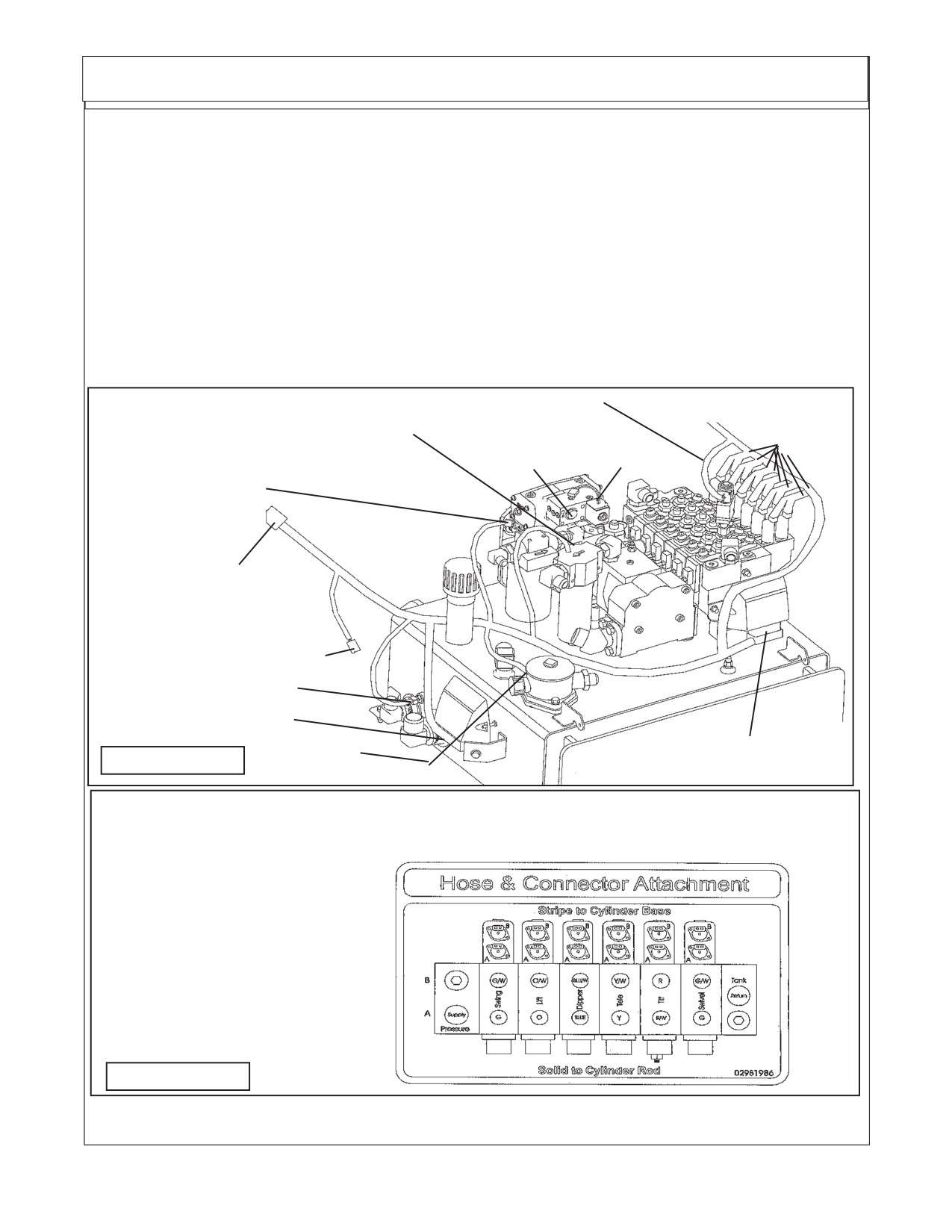
Exterior Wire Harness Schematic P/N 02981375A
13.
Exterior Wire Harness. The exterior wire harness will run from the cab of the tractor to the front.
It will include the wiring for the sensors at the pump. The connections for the valve actuator assemblies.
The electronic modules that are mounted to the right side of the tank and the module on the front of the
valve. The plugs have codes labeled on them, there is a matching code on them where the plugs are
connected. Some plugs have instructions and/or color codes. Read the next pages of this manual to
become familiar with the wire harness connections. There are two electronic modules bolt on the tank
assembly in the front of the tractor. The XT2 module bolted on the right hand side of the tank and the XP2
bolt on the LH side in front of the 6 spool valve. (See Figure 25, 27 & 28). The exterior wiring harness should
be laid out and connections need to be start at the first connection coming from the tractor cab connection,
this allows the harness to be moved around and under components as needed.
NOTE; V1 Pump Solenoid 2 is only used when the Timbercat Head is installed and will be installed into
plug next to Pump solenoid 1 which is used with all heads. Note: Unless the timbercat head is used only
Solenid 1 will be installed which is Plug V1, leave plug T1 tie to othrer plug out of the way.
H1 & H2 ( Lock Valve Connection)
BB (Diverter Valve)
Y1 Connect to White Wire & Y2 Connect
Pump Solenoid
AA (See
to Black Wire ( Valve Filter)
T1 (Sol 2) & V1(Sol1)
Below)
W1 (Charge Filter)
G2 (Plug to Interior
Wire Harness)
R1 (Cooler Fan)
S1 (Temp Sensor)
E (XT2 Module)
X1 & X2
F (XP2 Module)
FIGURE 25
(Return Filter)
Plug Valve
Valve
Decal Below shows the Hose location and Plastic tie color on hose.
Label Function
Label
Also the markings for the wire harness plugs on valve ("A" or "B")
AA1
Swivel
B
See Figure 18 & 18A)
AA2
Swivel
A
AA3
Tilt
A
AA4
Tilt
B
AA5
Telescope
A
AA6
Telescope
B
AA7
Dipper
A
AA8
Dipper
B
AA9
Lift
A
AA10
Lift
B
AA11
Swing / Door
A
AA12
Swing / Door
B
FIGURE 26
NOTE; Decal, Stripes to Base and Solid to Rod end refers to the plastic ties on hoses only &
not electricl connections
Maverick (NH TS-100A,115A, 125A, 135A Asy. Man) 01/05
Section 8 - 11
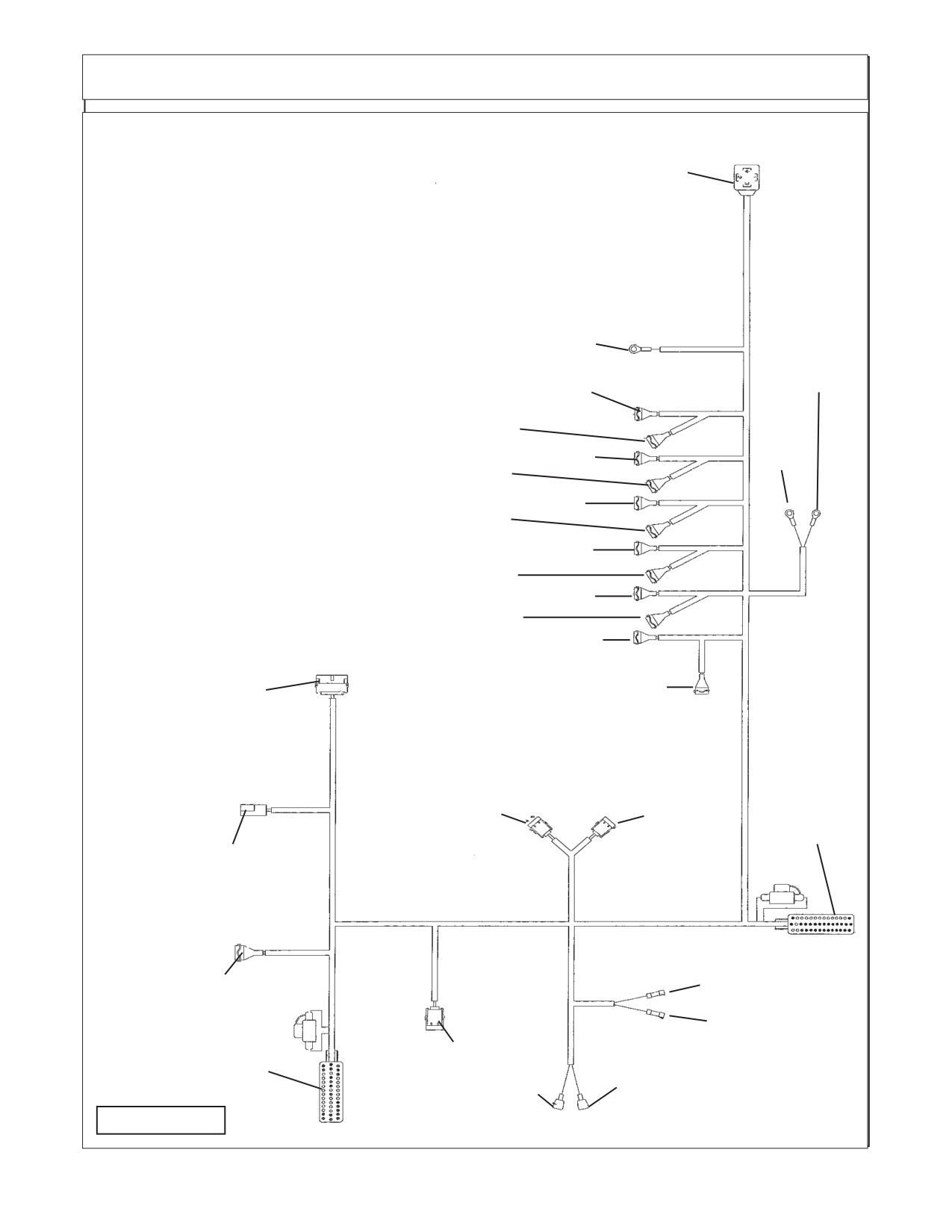
Exterior Wire Harness Schematic P/N 02981375A
AA1
Swivel Cylinder, CCW
Connection Markings on Exterior Wire Harness:
AA2
Swivel Cylinder, CW
AA3
Tilt Cylinder, Down
AA4
Tilt Cylinder, Up
BB
AA5
Telescope Cyl, IN
AA6
Telescope Cylinder, Out
AA7
Dipper Cylinder, Down
AA8
Dipper Cylinder, Up
AA9
Lift Cylinder, Down
AA10
Lift Cylinder, Up
AA11
Swing / Door
AA12
Swing / Door
BB
Solenoid Valve Connection for Diverter Valve
Z1
E
Connector XT2 Module
H2
F
Connector XP2 Module
AA12
G2
Exterior Harness to G1 Interior Harness
H1
Lock Valve Connection
AA11
H2
Lock Valve Connection
R1
Cooler Fan Connection
AA10
H1
S1
Temperature Connection Sensor
AA9
T1
Pump Solenoid 1 Connection
AA8
V1
Pump Solenoid 2 (Only on Timbercat Head)
AA7
W1
Charge Filter connection
X1
Return Filter Connection
AA6
Y1
Common, Connect to White Wire at Filter
AA5
Y2
Signal, Connect to Black Wire at Filter
AA4
Z1
Negative Chasis Ground
AA3
AA2
G2
AA1
V1
T1
F
R1
S1
Y2
Y1
W1
E
X2
X1
FIGURE 27
Maverick (NH TS-100A,115A , 125A, 135A Asy. Man) 01/05
Section 8 - 12
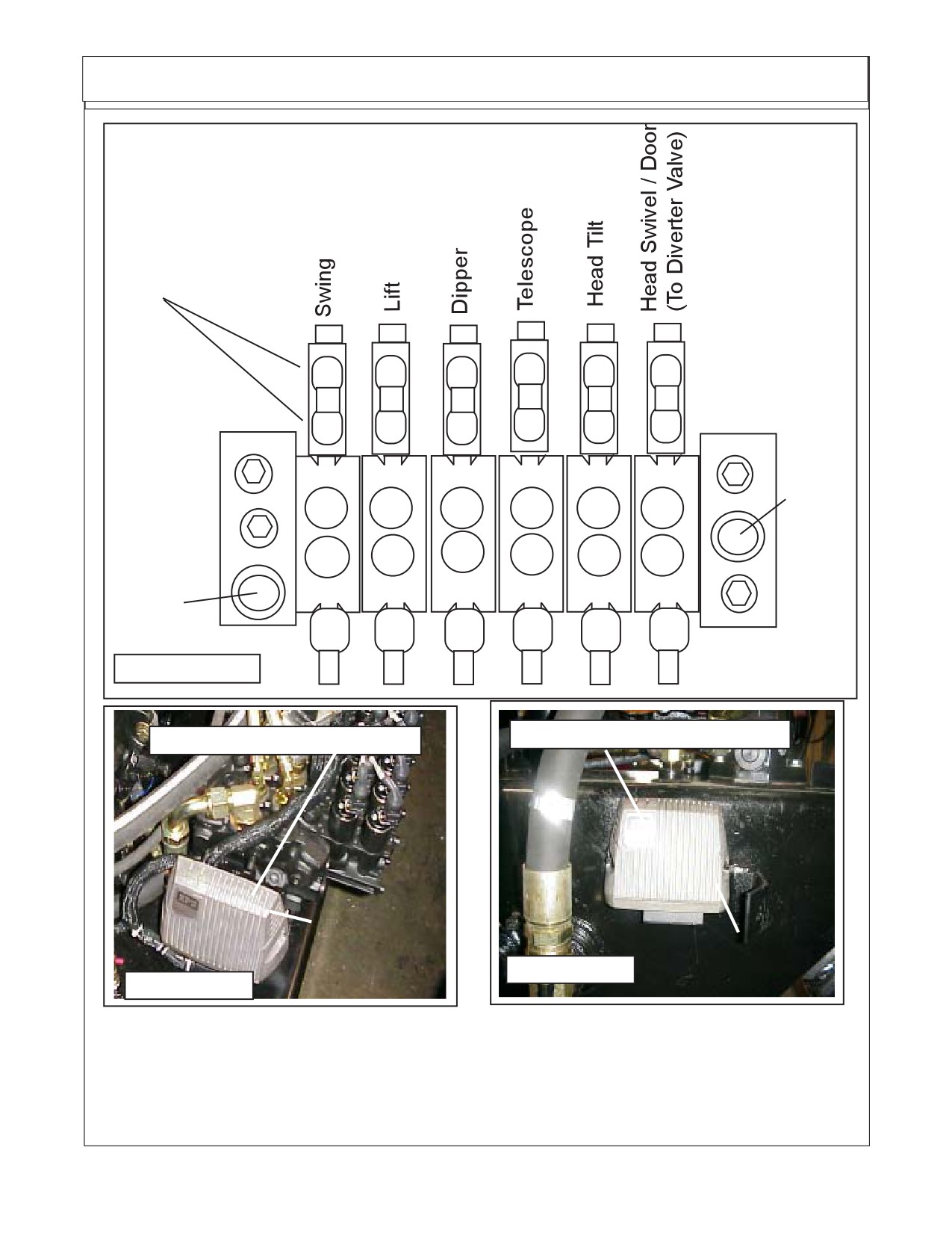
Exterior Wire Harness Schematic P/N 02981375A
Six Spool Control Valve
External Wire Connec-
tions for valve are marked
"A" and "B" on Valve &
AA1 thru AA12 on wire
harness connections
B
B
B
B
B
B
AA
AA
AA
AA
AA
AA
12
10
8
6
4
1
AA
AA
AA
AA
AA
AA
11
9
7
5
3
2
A
A
A
A
A
A
"B"
"B"
"B"
"B"
"B"
"B"
OR/
Return
Y/W
R
G/W
G/W
B/W
W
To Tank
"T"
B
Y
R/W
G
G
OR
Pressure
"A"
"A"
"A"
"A"
"A"
"A"
Supply
Port "P"
FIGURE 28
XT2 (Expansion, Transmission)
XP2 (Expansion, Power)
Bolts on LH side
in front of Valve
Bolts on RH side
FIGURE 30
on side of Tank
FIGURE 29
14.
Diverter Valve Wiring Connection: The plug for the diverter valve is at the end of the exterior
wiring harness and will be marked with code BB. The plug and wire will run down the LH side of tractor
from the front mounted hydraulic pump / Tank. The diverter valve is bolted the the LH front Frame
Mount bracket. The holes are already in the bracket and the diverter valve should have already been
mounted. If valve has not been mounted it can be mounted now (See Figure 27, 28 , 31 & 38).
Maverick (NH TS-100A,115A, 125A, 135A Asy. Man) 01/05
Section 8 - 13
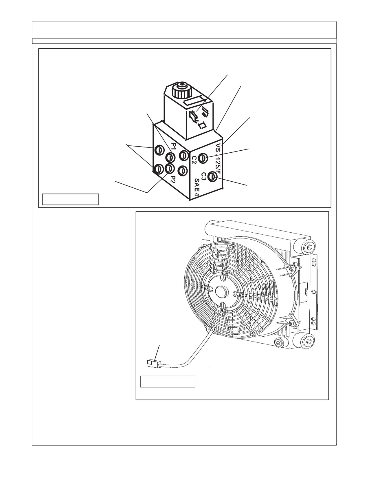
Exterior Wire Harness Schematic P/N 02981375A
Diverter Valve Wire Harness Connection BB of
exterior harness connects here
Diverter Valve
Diverter Valve "C1" Port
to Swivel Cyl Base
End Port (G/W Tie)
Valve "B" Port to
Diverter valve P1 Port
Diverter Valve "C4" Port
(G/W Tie)
to Swivel Cyl Rod End
Port (G Tie)
4 Through holes are
Diverter Valve "C2" Port
mounting holes
to Door Cyl Base End
Port (Y/W Tie)
Valve "A" Port to
Diverter valve P2 Port
(G Tie)
Diverter Valve "C3" Port
to Door Cyl Rod End
FIGURE 31
Port (Y Tie)
Connecting Oil Cooler
And Fan Assembly to Ex-
terior Wire Harness
15.
Oil Cooler / Fan As-
sembly. The Oil cooler / fan
assembly is for cooling the oil
being returned from the Motor
Case Drain. The fan is con-
nected to the control box and
is turned on & off automati-
cally. It set to run on a program
that will run the fan in the cool-
Exterior wire
harness connec-
ing rotation for a designated
tion marked R1
time, then stop, reverse the
connects here
rotation (cycle to clean debris
off of cooler, then stop and
reverse the fan again and be-
gin the cycle all over again.
The connection to the
FIGURE 32
cooler on the exterior wire har-
ness is marked with code R1.
The connection from the fan
will have two wires, a Blue (+
connection) and a black (- con-
nection) (See Figure 32).
Maverick (NH TS-100A,115A , 125A, 135A Asy. Man) 01/05
Section 8 - 14
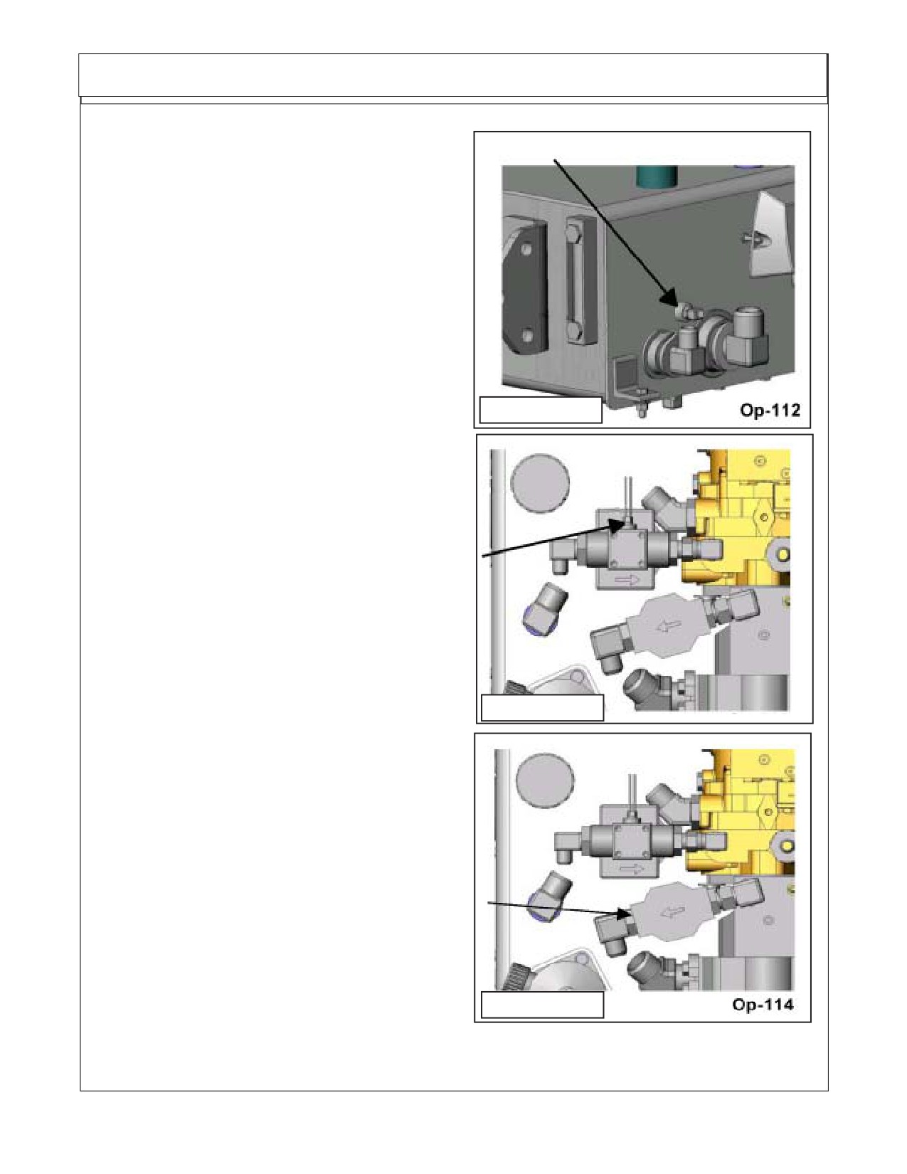
Exterior Wire Harness Schematic P/N 02981375A
Maverick Sensor Connections:
1.
Instrumentation The Maverick Boom utilizes
instrumentation for certain decision making activi-
ties. Listed below are the sensors included on this
unit. Tank Temperature Sensor, Charge Pressure
Filter Switch, Valve Pressure Filter Switch and Re-
turn Filter Switch.
2.
Tank Temperature Sensor. The tank tem-
perature sensor monitors the fluid temperature in
the area of the pump suction screens. the tempera-
ture is real time and is used on the network to
accomplish certain objectives. The first, is to display
FIGURE 33
on the interface while the cutter circuit is operating.
The second, is to be used to control the electric fan
on the hydraulic cooler. At any time the fluid level
reaches 150° F. the fan is activated and remains
activated until fluid temperature drops to or below
the desired temperature (See Figure 33).
3.
The Charge Pressure Filter Switch The
charge filter pressure switch has three wire coming
out of it, a white , black and Blue wire. The Blue wire
will not be used and will be cut off. The charge
pressure filter switch is located at the filter in the
charge loop on the hydrostatic pump (See Figure
34). The sensor monitors the back pressure created
by the filter element when in use. When the back
FIGURE
34
pressure reaches a setting of 50 psi the switch will
trigger and prompt the operator for a filter element
change of filter element.
4.
The Valve Pressure Filter Switch The Valve
pressure filter switch is located at the pressure filter
in the valve pressure circuit, between the closed
center load sense pump and the control valve (See
Figure 35). The sensor monitors the back pressure
created by the filter element when in use. When the
back pressure reaches a setting of 50 psi the switch
will trigger and prompt the operator for a filter
element change.
WARNING! This filter does not have a by-
pass. The element must be changed at the appropri-
FIGURE
35
ate time to avoid element damage and system
contamination.
Maverick (NH TS-100A,115A, 125A, 135A Asy. Man) 01/05
Section 8 - 15
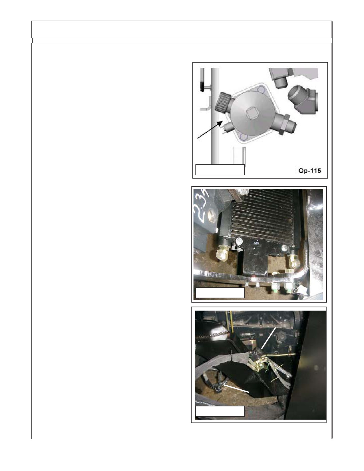
Exterior Wire Harness Schematic P/N 02981375A
5.
The Return Filter Switch. The return filter
switch is located at the return filter mounted on to the
tank top. The fluid returning from the cylinder control
valve is filtered before returning to tank at this loca-
tion (See Figure 36). The sensor monitors back
pressure created by the filter assembly while cylin-
der circuit is in operation. When the back pressure
reaches 25 psi the switch will trigger and prompt the
operator for a filter element change.
WARNING! This filter does not have a by-
pass. The element must be changed at the appropri-
ate time to avoid element damage and system
contamination.
6.
Oil Cooler & Fan Assembly. The oil cooler /
fan assembly bolts to the tank rail mount bracket
FIGURE
36
between tractor front axle and hydraulic tank. The
mounting holes are in the tank rail mounting brack-
ets (See Figure 37). There will be two hose con-
nected to the cooler, one from the motod case drain
to the cooler and one from the cooler to the tank
return, These hose will have blue plastic ties on
them.
FIGURE 37
Diverter Valve
Diverter Valve Plug
FIGURE 38
Maverick (NH TS-100A,115A , 125A, 135A Asy. Man) 01/05
Section 8 - 16
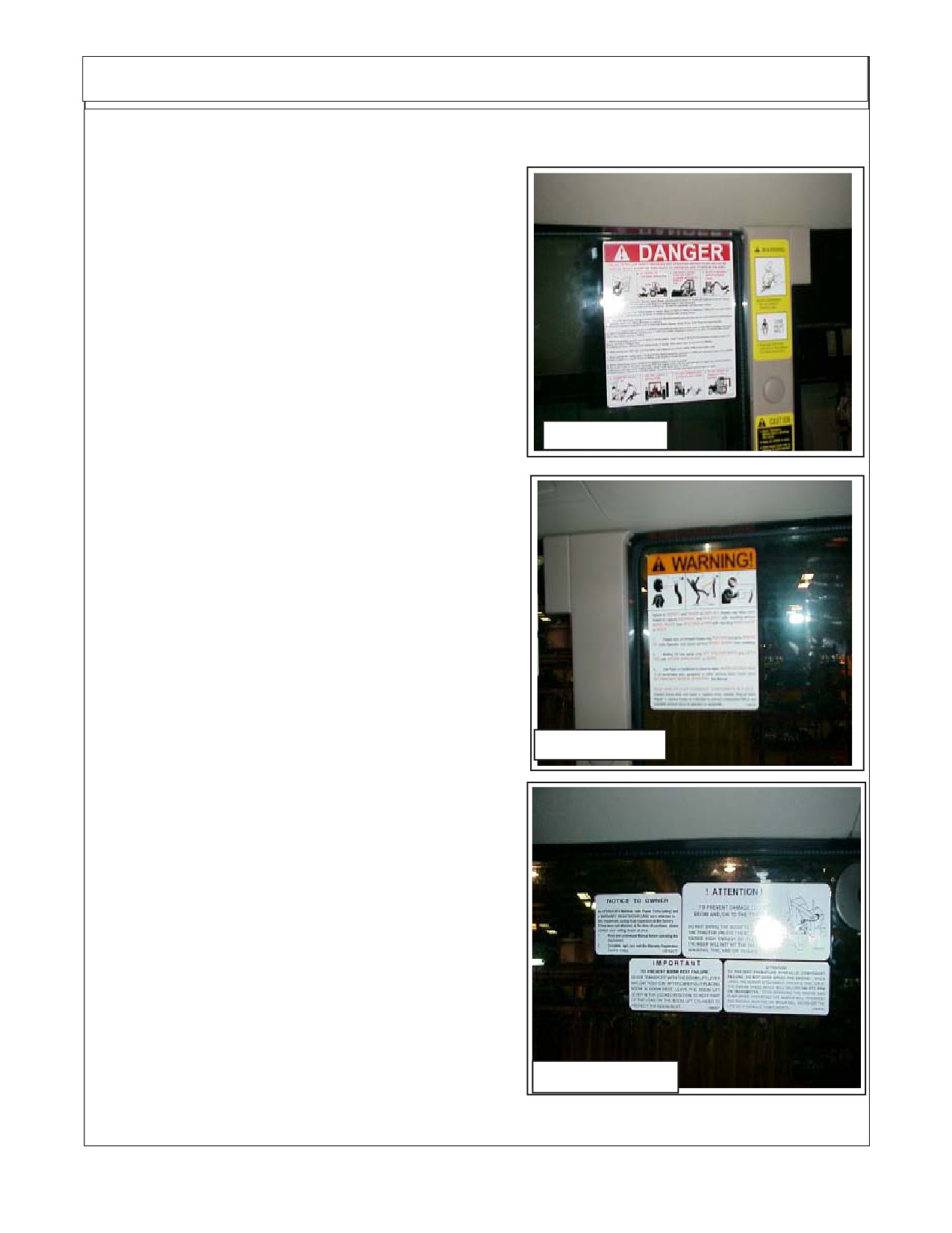
Decal Mounting
Installing Warning and
Instruction Decals:
1.
Always clean windows before installing
decals. Windows must be dry and free of any oil,
after cleaning do not touch windows before decals
are installed. Take precaution to make sure decals
are right side up and straight when installing them,
they cannot be taken off and redone.
2.
Identify Decals. Lay all the Decals out and ID
each one so you will know which is installed where.
The Decals will have the Part Number on them in the
lower corners.
02967827
Decal No. Description
00763977
Notice to Owner
FIGURE
39
02964677
Important - Boom Rest
02963524
Attention - Boom Swing
02965093
Proper Engine Operating
02965262
Warning - Hose Burst
02967827
Multi - Hazard
3.
Multi-Hazard - Danger Decal. This is in-
stalled on the Left Side Window of Cab on the inside
to Drivers Left. P/N 02967827 (See Figure 39)
4.
Warning Hose Burst Decal. This installs on
the Right Side Window of Cab on the Inside to
Drivers Right P/N 02965262 . (See Figure 40)
02965262
FIGURE 40
5.
Notice To Owner Decal. This installs on the
inside top rear of Right Door Glass P/N 02964677 (See
Figure 41)
6.
Attention Boom Swing Decal. This installs on the
inside top rear of Right Door Glass P/N 02963524 (See
02963524
Figure 41)
00763977
7.
Important Boom Rest Decal. This installs on the
inside top rear of Right Door Glass P/N 02964677 (See
Figure 41)
8.
Proper Engine Operating Decal. This installs on
the inside top rear of Right Door Glass P/N 02965093 (See
02964677
02965093
Figure 41)
FIGURE 41
Maverick (NH TS-100A,115A, 125A, 135A Asy. Man) 01/05
Section 8 - 17