New Holland. Cab 2 WD / 4 WD TS-100A, TS-115A, TS-125A, TS-135A. ASSEMBLY MANUAL - page 1
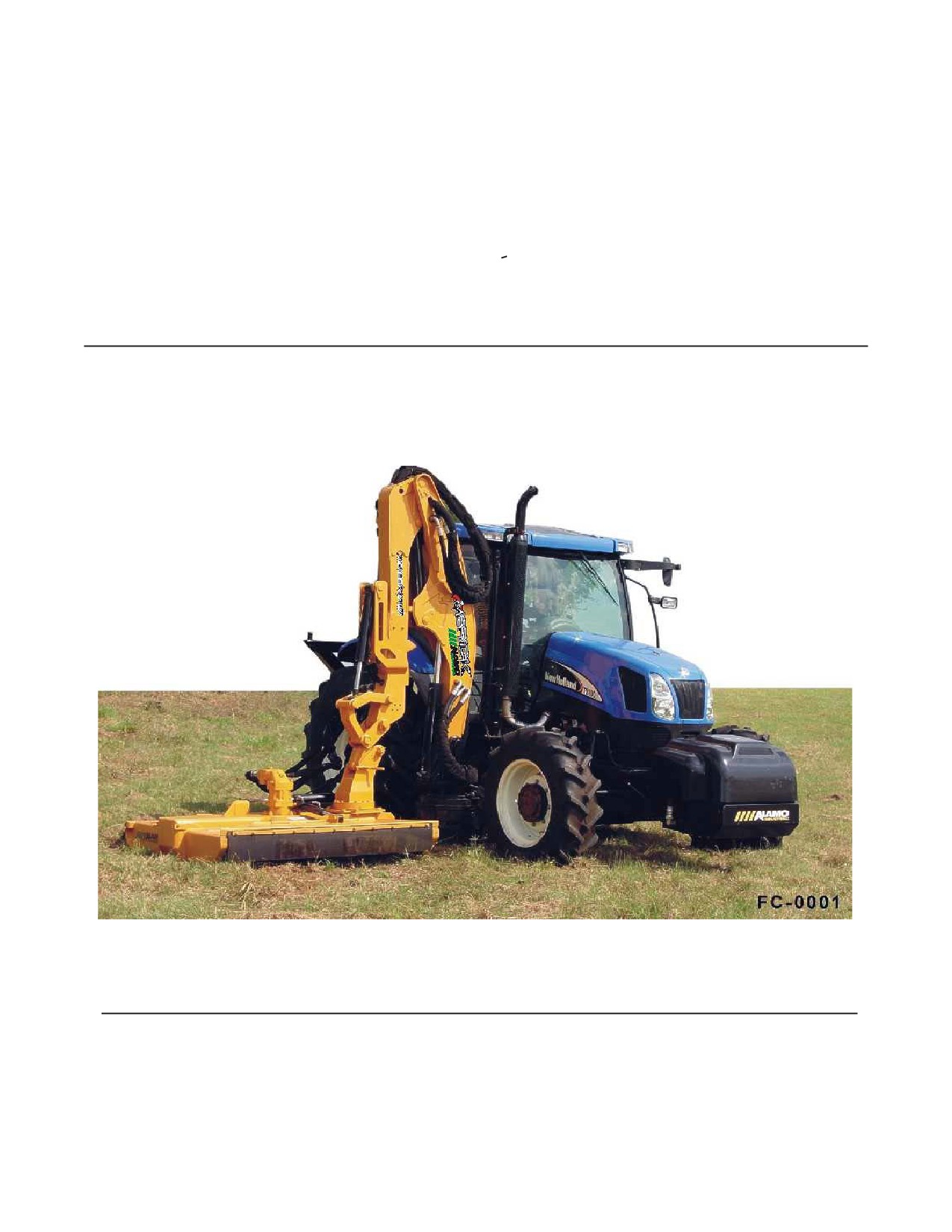
BOOM ARM MOWER
Assembly Instruction Manual
New Holland - Cab 2 WD / 4 WD
TS-100A, TS-115A, TS-125A, TS-135A
Published 01-05
Part No. 02982279
ASSEMBLY MANUAL
Tractors equipped with additional options, special equipment, tractor manufacturer modifications,
new tractor models, or Customer alterations may prevent this Mount Kit from being properly
mounted to the tractor. Alamo Group is not responsible for modifications to the MountKit to
accommodate these differences.
ALAMO INDUSTRIAL
1502 E. Walnut
Seguin, Texas 78155
210-379-1480
TO THE OWNER/OPERATOR/DEALER
All implements with moving parts are potentially hazardous. There is no substitute for a cautious, safe-minded operator who
recognizes the potential hazards and follows reasonable safety practices. The manufacturer has designed this implement to
be used with all its safety equipment properly attached to minimize the chance of accidents.
BEFORE YOU START!! Read the safety messages on the implement and shown in your manual.
Observe the rules of safety and common sense!
WARRANTY INFORMATION:
Read and understand the complete Warranty Statement found in this Manual. Fill out the Warranty Registration Form
in full and return it within 30 Days. Make certain the Serial Number of the Machine is recorded on the Warranty Card
and on the Warranty Form that you retain. The use of "will-fit" parts will void your warranty and can cause catastrophic
failure with possible injury or death.
INTRODUCTION
ABOUT THIS MANUAL:
The intent of this publication to provide the competent technician with the information necessary
to perform the CORRECT Assembly to the Alamo Industrial Product. This will, in turn provide for
complete customer satisfaction
It is hoped that the information contained in this and other Manuals will provide enough detail to
eliminate the need for contact of the Alamo Industrial Technical Service Dept. However, it should be
understood that many instances may arrive where correspondence with the Manufacturer is neces-
sary.
CONTACTING MANUFACTURER: (Please help us Help You! Before You Call! )
Alamo Industrial Service Staff Members are dedicated to helping you solve your problem, or
your customer’s service problem as quickly and efficiently as possible. Unfortunately, we receive
entirely to many calls with only a minimum amount of information. In some cases, the correspondent
has never gone out to look at the equipment and merely calls inquiring of the problems described to him
by the operator or customer.
Most calls received by Alamo Industrial Service can be classified into approx. 6 general categories.
1.
Hydraulic or Mechanical Trouble Shooting.
2.
Request for Technical Information or Specifications.
3.
Mounting or Fitting Problem.
4.
Special Service Problem.
5.
Equipment Application Problems.
6.
Tractor Problem Inquiries.
HOW YOU CAN HELP:
Make sure the call is necessary! Most of the calls received may not be necessary if the Dealer
Service Technician would do the following.
1.
Check the Service Information at your Dealership provided by Alamo Industrial, This
would include, Service Bulletins, Information Bulletins, Parts Manuals, Operators Manuals, Assembly
Manual or Service Manual, many of these are available via the Alamo Industrial Internet site (www.Alamo-
Industrial.Com). Attempt to diagnose or repair problem before calling.
2.
If a call to Alamo Industrial is needed, Certain Information should be available and ready
for the Alamo Industrial Service Staff. Such information as, Machine Model, Serial Number, Your Dealer
Name, Your Account Number and Any other information that will be useful. This information is vital for
the development of a prompt and correct solution to the problem. This will also help to develop a
database of problems and related solutions, which will expedite a solution to future problems of a similar
nature.
3.
The technician may be asked to provide detailed information about the problem
including the results of any required trouble shooting techniques. If the information is not available, The
technician may be asked to get the information and call back. Most recommendations for repairs will
be based on the procedures listed in the Service Manual / Trouble Shooting Guide and Information
provided by customer.
CONTACT ALAMO INDUSTRIAL:
Alamo Industrial, 1502 E. Walnut St. Seguin TX. 78155, Technical Service Dept. PH: 830-379-1480
Maverick (NH TS-100A,115A, 125A, 135A, Asy. Man) 01/05
Index -1
INDEX - ASSEMBLY INSTRUCTION
Page
Introduction
Manual Introduction
Index-1
Section 1 - Model Specifications
DO NOT DO LIST (IMPORTANT)
1-2
Maverick Boom Specifications
1-3 to 1-6
Hose Fitting Torque Chart
1-6
Bolt Torque Chart
1-7
Section 2 - Tractor Preparation
General Information
2-2 to 2-8
Section 3 - Pump & Driveshaft Installation
Remove Engine Guards for Access to engine compartment
3-2
Pulley Adapter Installation
3-2
Install Shaft Half of Driveshaft
3-3
Install Tank Mount Rails
3-4
Install Pump
3-4 to 3-7
Reinstall Engine Guards & Covers
3-8
Section 4 - Hydraulic Tank & Control Valve Installation
Install Hydraulic Tank to Tank Mount Rails
4-2
Tank Hose Routing
4-2 to 4-3
Control Valve Fitting Identification
4-4 to 4-5
Head Tilt Lock Valve
4-5
Valve Hose Marking Codes
4-6
Diverter Valve
4-6 to 4-8
Oil Cooler & Cooling Fan Assembly
4-9
Section 5 - Battery, Exhaust, Fuel Tank Modification & Main Frame Installation
Battery Relocation / Modification
5-2
Exhaust relocation / Modification
5-3
Fuel Tank Installation / Modification
5-4 to 5-5
Under Mount Component Information
5-6 to 5-7
Frame Installation
5-8 to 5-11
Boom Rest Installation
5-11
Frame Counter Weight Installation
5-12
Boom Turret Assembly Installation
5-13 to 5-14
Front Axle Stabilizer Kit
5-15
Maverick (NH TS-100A,115A, 125A, 135A, Asy. Man) 01/05
Index -2
INDEX - ASSEMBLY INSTRUCTION
Page
Section 6 - Lexan Door Installation
Lexan Door Installation
6-2 to 6-4
Section 7 - LH Wheel Weights
Standard Wheel Weight
7-2 to 7-3
Auxiliary Wheel Weight
7-4
Section 8 - Joystick / Wire Harness / Valve Installation
Wire Harness tractor Preparation
8-2
Replace Tractor Seat Arm Rest
8-3
"E"-Stop Switch Installation
8-4
Joystick Installation
8-4 to 8-6
XS Module Installation
8-6 to 8-8
Interior Wire Harness Installation
8-7 to 8-10
Exterior Wire Harness Installation
8-11 to 8-13
Diverter Valve Harness Connections
8-14 to 8-16
Cab Decals
8-17
Section 9 - Boom / Head Installation
Boom Mounting
9-2 to 9-5
Boom Lift Cylinder Pin Installation
9-2 to 9-3
Boom Cylinder Schematic
9-6
Valve Hose Schematic
9-6
Hose Routing and Connecting
9-2 to 9-12
Hydraulic Hose Color Identification Codes
9-8 to 9-12
Tank Hose to Boom Connections
9-10 to 9-12
Tank Hose Schematic / Routing
9-11 to 9-12
Section 10 - Fill Oil Tank / Setting Electronic Display Controls
Fill Unit with Oil
10-2 to 10-3
Prime Pump
10-3
Setting Electric Display Control Box
10-4 to 10-11
Joystick Operation
10-12
front Pump & Tank Cover Installation
10-13
Section 11 - Mounting Specification / Component Identification
Mount Kit Components
11-2 to 11-37
Component Parts Identification / Descriptions
11-2 to 11-37
Section 12 - Pre-Delivery Inspection Check List
Check List
12-2 to 12-3
Maverick (NH TS-100A,115A, 125A, 135A, Asy. Man) 01/05
Index -3
NOTES
Maverick (NH TS-100A,115A, 125A, 135A, Asy. Man) 01/05
Index -4
Section 1
Model
Specifications
Maverick Boom
24' & 30'
Section 1 - 1
SPECIFICATIONS - MAVERICK
READ THIS BEFORE BEGINNING
ASSEMBLY, REPAIRS OR TESTING:
The Maverick has computerized electronics. The electronic
components can be damaged if care is not taken when performing repairs,
testing and/or during assembly.
DO NOT
1.
DO NOT short any wires across or allow them to be shorted out.
2.
DO NOT attempt to jump across any wires or supply them with alternate power
source.
3.
DO NOT install higher rated fuses than are recommended by manufacturer.
4.
DO NOT do any welding on unit unless the computer modules are unplugged first, this
is to prevent a power surge going into modules (THIS IS VERY IMPORTANT). This could
also apply to the tractor components. Check Tractors repair guide for specific instruction
about tractor model and type.
5.
DO NOT attempt to repair or adjust a component that is not intended to be repaired,
example sealed components as there are no serviceable components inside.
6.
DO NOT let anyone attempt any testing or repairs unless they are an experienced
and qualified technician. Technicians must have proper tools, gauges, meters etc. to
perform proper diagnosis and/or repairs.
7.
DO NOT perform any repairs with dirty tools or in dirty area. When working on hydraulic
components keeping system clean and free of contamination is important.
8.
DO NOT start or engage system if the oil level is not at the proper level or condition. Never
start or run unit low or out of oil.
9.
DO NOT install / add any oil unless you know it is the correct type and the container is
clean. Make certain the oil is not contaminated with dirt or any liquid.
Section 1 - 2
SPECIFICATIONS - MAVERICK
1. CUTTING CIRCUIT SPECIFICATIONS
Hyd. Pump Speed (Front Aux Pump)
1950 RPM
Hyd. Motor Speed
1220 RPM
Hyd. Motor Rated HP
199 HP
Hyd. Motor Rotation (as viewed f/ Top of the Deck)
CW (Clockwise)
Relief Valve Setting At Motor
4000 PSI
Relief Valve Setting At Pump
4500 PSI
Hyd. Pump Flow (Front Pump @ 1950 RPM)
25.3 GPM
Hyd. Oil Operating Temperature @ 100° F Ambient
155 - 165 ° F.
Hyd. Oil Filtration, (Discharge f/ Charge Pump)
10 Micron
Hyd. Tank Capacity
17-1/2 Gal.
Hyd. Motor Start Stop Time (Approximate)
6 Seconds
Cutting Diameter, (Rotary Head)
58 Inch
Spindle
4.5 “ by 9” Heat Treated Alloy
Blade Bar Type
Stacked 3 Leaf
Blade Bar Size
1-1/4” Thick X 5" Wide (Ea. Leaf)
Blade Bar Material
T1 Steel (bottom) & HRFB Steel (top & Middle)
Blade Swing
360 Deg Swing
Blade Material
High Carbon Alloy Steel
Cutter Weight. (Approximate w/ Rotary Head)
950 lbs.
Cutter Deck Opening & Closing
Hyd. Operated Door
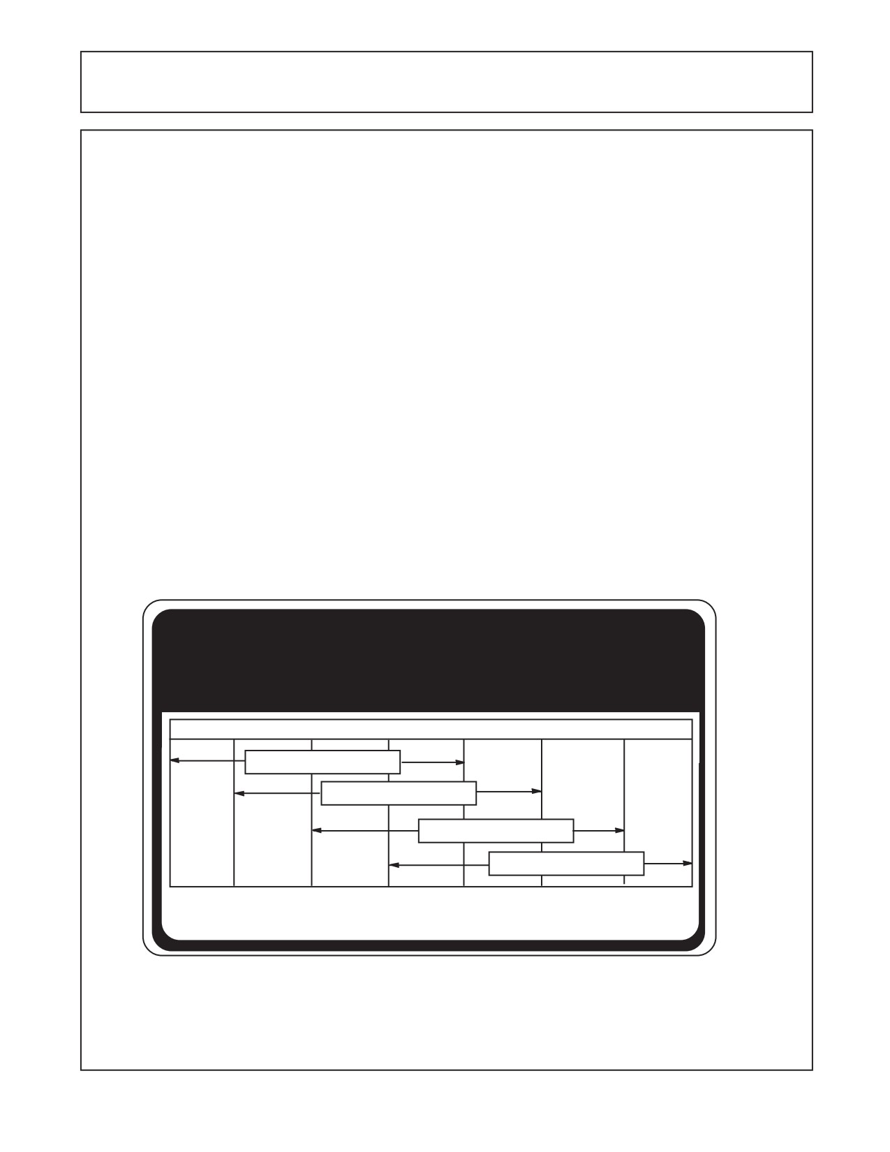
Recommended Hydraulic Oil
ISO AW Hyd. Oil (See decal below)
Fluid Cleanliness level
ISO 16/14/11
ATTENTION
10°F 20°F
30°F
40°F
60°F
70°F
90°F
110°F
AW ISO VG 32
AW ISO VG 46
AW ISO VG 68
AW ISO VG 100
The correct hydraulic fluid is dependent upon ambient
temperature. Refer to chart when selecting proper grade
02982828
Section 1 - 3
SPECIFICATIONS - MAVERICK
2. BOOM SPECIFICATIONS
Boom Reach 24 Foot Boom
Out 24'
Boom Reach 30 Foot Boom
Out 30'
Frame
Manufactured Box Sections
Pins
Chrome Plated Alloy
Bushings
Greasable
Weight, 24' Boom
1250 lbs.
Weight, 30' Boom
1450 lbs
Boom Rest
Tractor Axle Mounted
Boom Mounting
ROPS or CAB Tractor Optional
3. FILTRATION
Control Valve Functions: Control functions include All Hydraulic Cylinders used to manipulate the
Maverick Boom. The boom and frame cylinders are powered by a self contained hydraulic system. The
pump is loctated on the front of the tractor. There is an in-line pressure filter (P/N 02981371) between
the closed center load sense pump and cylinder control valve. There is a return filter (P/N 02981391)
mounted to the tank that filters the fluid returning from the control valve to the tank. Filter change
recommended for every 200 to 250 hours. An electronic monitoring system monitors element back
pressure for indication of clogged filter prior to element change.
Mower Head Functions: Mower Head Functions are operated by Pump, which is mounted to the
front of the Tractor Engine. This will have an in-line Filter installed into hydraulic circuit, This filter should
be changed on a regular maintenance schedule. Filter are rated by Micron size (10 Micron), Filters
should be replaced with original Alamo Industrial Replacement Filters to make certain the correct
rated filter element is installed at all times. (Pressure Filter is P/N 02968922 and Return Filter
Replacement Element is P/N 02968923)
4.
HYDROSTATIC PUMP SPEC'S
Cutter Head Pump Circuit Spec's:
Pump Type
Piston Type
Pump Speed (Front Engine Mounted)
Run Engine to 540 PTO Speed
Relief Setting at the Pump
4500 PSI
Pump Flow (Front Engine Operating Speed)
25.3 GPM
Boom Cylinder Pump Circuit Spe'c's:
Pump Type
Piston Type
Pump Speed
1800 RPM
Pump Flow (Front Engine Operating Speed)
15.6 GPM
Low Pressure Standby
250 PSI
High Pressure Comp
3000 PSI
Horse Power at 1850 RPM (Engine Speed)
28.5 HP
5.
HYDRAULIC HOSE CODES
Hydraulic Hose Band Mark Color Codes:
Hose's and/or fittings are marked with a Color Coded Plastic Band around it. Some Bands
are a solid Color and some have a Colored with a Stripe. The purpose of the colored bands
are to provide a quick reference for hose and port connection. A metal band is also attachted
to the hose, on that band is an Alamo Industrial Part Number for reference if needing a
replacement hose. Always Check Hose Size, Color Code & Part Number
Section 1 - 4
SPECIFICATIONS - MAVERICK
Boom Cylinder Circuit Hoses:
Color Tie
(Code) Hose Size
Hyd. Function
Green
G
SAE # 6
Swing, Back (Rod End)
Green / White
G/W
SAE # 6
Swing, Forward (Base End)
Orange
OR
SAE # 6
Lift, Down (Rod End)
Orange / White
OR/W
SAE # 6
Lift, Up (Base End)
Blue
B
SAE # 6
Dipper, In (Rod End)
Blue / White
B/W
SAE # 6
Dipper, Out (Base End)
Yellow
Y
SAE # 6
Telescope, In (Rod End)
Yellow / White
Y/W
SAE # 6
Telescope, Out (Base End)
Red
R
SAE # 6
Head Tilt, Up (Rod End)
Red / White
R/W
SAE # 6
Head Tilt, Down (Base End)
Green
G
SAE # 4
Swivel, CW (Rod End)
Green / White
G/W
SAE # 4
Swivel, CCW (Base End)
Yellow
Y
SAE # 4
Door, Open (Rod End)
Yellow / White
Y/W
SAE # 4
Door, Closed (Base End)
Motor Circuit Hoses:
Color Tie
(Code) Hose Size
Hyd. Function
Red
R
SAE # 16
Pressure Flow to Motor
Orange
OR
SAE # 16
Return Flow From Motor
Blue
B
SAE # 8
Case Flow From Motor to Boom
Blue
B
SAE # 12
Case Flow at Boom to Tank
6.
HYDRAULIC CYLINDER PRESSURE RATES:
Cylinder Type
Welded Cylinders
Cylinder Working Pressure
3000 PSI
Hydraulic Cylnder Repair Specs:
Cylinder
Cylinder
Piston Nut
Gland
Seal Kit
Part No.
Function
Torque ft. lbs. Torque ft. lbs.
Part No.
02981275
Swing
400-500
80-120 (Head)
02982066
02981278
Lift
(30 ft.)
400-500
80-120 (Head)
02982069
02981279
Lift
(24 ft.)
400-500
80-120 (Head)
02982070
02981277
Dipper
400-500
80-120 (Head)
02982068
02981280
Tilt
400-500
80-120 (Head)
02982071
02961480A
Door (Rotary)
150-250
80-120 (Head)
02975528
02970710A
Door (Flail Axe)
40-60
80-120 (Head)
02975532
02971423
Slide (Timber Cat)
400-500
50-60 (Tie Rod)
02973505
02811000A
Door (Ditcher)
150-250
80-120 (Head)
02975528
02981316
Stabilizer
40-60
80-120 (Head)
02982073
02981315
Swivel (Rotary)
300-400
80-120 (Head)
02982072
02981276
Extension
300-400
80-120 (Head)
02982067
Section 1 - 5
SPECIFICATIONS - MAVERICK
7. VALVE SPECIFICATIONS
Valve Type: Multi-Section, Load Sense, Pressure Compensated, Directional control Valve.
Features electro-hydraulic spool actuators for proportional characteristics.
Valve Construction: Multi-Section, Individual Spool, with electro-hydraulic solenoids. Tie rod
bolt together type.
Valve Controller: Mechanical over Electric. 3-axis, multi-function, lever-type joystick.
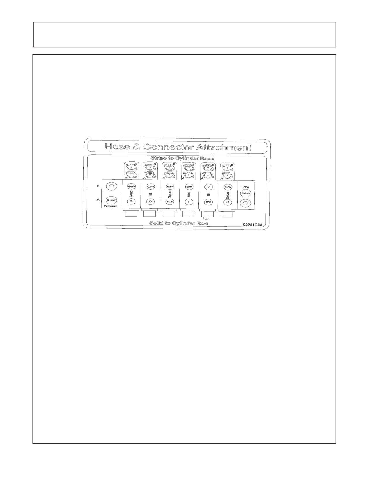
Valve Porting and Hose Connections: Hoses connect to valve as shown by color code. See
Decal P/N 02981986 below, Electrical connections connect as shown, Reference label on
connector and corresponding solenoid.
8. Valve Spool Functions & Spec's (Boom Feature):
Main Relief at Inlet 3335 psi - Valve Spool Functions & Specs:
Band
Spool
Cyl.
Travel
Port
Work Port
Pressure
Color
No.
Function Direction
Relief
Rating
G/W
1
Swing
Forward
B
3045 psi.
2.0
G
1
Swing
Back
A
3045 psi.
2.0
OR
2
Lift
Down
B
1160 psi.
7.92
OR/W
2
Lift
Up
A
Plug
7.92
B/W
3
Dipper
Out
B
Plug
3.17
B
3
Dipper
In
A
1160 psi.
3.17
Y/W
4
Telescope Out
B
2030 psi
3.17
Y
4
Telescope In
A
Plug
3.17
R/W
5
Tilt
Up
A
Plug
3.17
R
5
Tilt
Down
B
2030 psi
3.17
G
6
Swivel
CW (top)
A
2755 psi
6.60
G/W
6
Swivel
CCW (top) B
2755 psi
6.60
Valve Spool Functions & Specs: The Cylinder Cycle has adjustable settings, slow, medium
and fast, Time Cylinder cycle of unit, Time indicates the time for the Cylinder to travel the full amount of
its extension or retraction. The lift times up and down are taken with the dipper fully extended and begin
with the Deck flat on the ground. All Cycle times are measured at the rated Tractor RPM. Test Times
should vary as according to the setting being used.
Valve Leakage: Maximum internal Valve Leakage from the Cylinder. Ports to Tank at any Valve
Segment, Oil Pressure at 1450 PSI and Oil Viscosity at 102 SSU
= 1.25 Cubic Inch / Minute
Standby (Pilot) Pressure: Standby (Pilot) Pressure = 200 to 250 PSI.
Section 1 - 6
SPECIFICATIONS - MAVERICK
9. HOSE END FITTING TORQUE SPECS:
Hose End Type: 37 Degree Angle End Steel Hose End Fittings*
Dash
Nominal Cyl.
Torque
Torque
Size
Size (in.)
in. lbs.
ft .lbs.
-4
1/4"
140
12
-6
3/8"
230
19
-8
1/2"
450
38
-10
5/8"
650
54
-12
3/4"
900
75
-16
1"
1200
100
-20
1-1/4"
1600
133
-24
1-1/2"
2000
167
-32
2"
2800
233
* Straight Threads do not always seal better when higher torques are used. Too much torque causes
distortion and may lead to leakage. DO NOT over torque fittings and DO NOT allow any contaminants
to enter system through fittings when installing them.
10.
Special Torque Specifications (Rotary Heads)
Motor to Spindle Housing
100 ft. lbs.
Spindle to Deck
425 ft. lbs.
Spindle to Adjusting Nut (Bearing Preload)
25 in. lbs. Rolling Torque
Blade Bar Leaf Bolts (
1-1/4" Bolts)
2000 ft. lbs.
Blade Bar to Spindle Bolts
400 ft. lbs.
Blade Bolts
400 ft. lbs.
Motor Plate
See Set Up Instructions
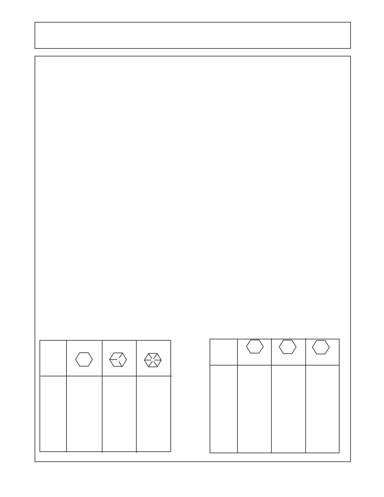
11.TORQUE VALUES - BOLTS: Recommended Torque, Ft. lbs. & (Nm)
IMPORTANT! Listed below IS BOLT TORQUE and NOT APPLICATION TORQUE, Component
Application Torque will vary depending on what is bolted down and the type material (Metal) that is being
bolted together. Thread condition and lubrication will vary Torque settings.
ALWAYS CHECK MARKINGS ON TOP OF BOLT HEAD OR OTHER BOLT DESCRIPTIONS
Inche Sizes
Metric Sizes
2 (B)
5 (D)
8 (F)
Bolt
Bolt
4.8
8.8
10.9
Plain Head
3 Dashes
6 Dashes
Dia.
Dia.
mm
ft. lbs (*N-M)
ft. lbs (*N-M)
ft. lbs (*N-M)
inch
6
5 (*6)
7 (*9)
12 (*16)
ft. lbs (*N-M)
ft. lbs (*N-M)
ft. lbs (*N-M)
8
11 (*15)
20 (*27)
25 (*33)
1/4
Not Used
10 (*14)
14 (*19)
10
20 (*27)
40 (*54)
58 (*78)
5/16
Not Used
20 (*27)
30 (*41)
12
37 (*50)
70 (*95)
105 (*142)
3/8
Not Used
35 (*47)
50 (*68)
14
60 (*81)
100 (*135)
140 (*189)
7/16
35 (*47)
55 (*75)
80 (*108)
16
92 (*124)
155 (*210)
200 (*271)
1/2
55 (*75)
85 (*115)
120 (*163)
18
118 (*159)
216 (*292)
280 (*379)
9/16
75 (*102)
130 (*176)
175 (*230)
20
160 (*217)
270 (*366)
355 (*481)
5/8
105 (*142)
170 (*230)
240 (*325)
22
215 (*291)
330 (*447)
430 (*583)
3/4
185 (*251)
300 (*407)
425 (*576)
24
285 (*386)
500 (*678)
700 (*949)
7/8
160 (*217)
445 (*603)
685 (*929)
27
450 (*610)
875 (*1186)
1000 (*1355)
1
250 (*339)
670 (*908)
1030 (*1396)
30
600 (*813)
1200 (*1627)
1700 (*2304)
1-1/8
330 (*447)
910 (*1234)
1460 (*1979)
33
800 (*1084)
1600 (*2169)
2300 (*3118)
1-1/4
480 (*651)
1250 (*1695)
2060 (*2793)
36
900 (*1220)
2100 (*2847)
3000 (*4067)
Section 1 - 7
NOTES
Section 1 - 8
Section 2
Maverick Boom
New Holland Tractor
TS-100A, 115A, 125A, 135A
Tractor Preperations
Maverick (NH TS-115A, 125A, 135A, Asy. Man) 01/05
Section 2 - 1
General Information / Installation Requirements
GENERAL INFORMATION:
The tools you will need at the assembly site are as follows:
1.
Impact wrench or socket and ratchet set.
2.
Rubber mallet.
3.
Box-end, Allen, and adjustable wrenches.
4.
Alignment pins.
5.
Forklift or hydraulic floor jacks with rolling back boards.
6.
Small chain hoist or block-and-tackle.
7.
Multidirectional Levels.
8.
Hydraulic Filter Buggy or Cart.
9.
Safety shoes, safety glasses, and gloves.
A hard hat should be worn by anyone working under any raised component.
Remember to follow each step closely and cautiously. Be aware of all support personnel at all times.
Keep the assembly area as clean as possible; clean up all spills when they occur. An uncluttered
assembly area and a crew that is sensitive to the hazards involved in putting this implement together
will help prevent accidents. Keep all unauthorized personnel from the area. Do not allow children near
the assembly site nor allow them on or near the tractor after assembly. There is no safe place for
anyone except the operator on the tractor and those assisting with the assembly.
To help you assemble your new Machete Boom and mount it to your tractor, a detailed assembly
instruction Manual is being provided with the mount kit to provide detailed instructions and part
numbers. Please consult this document for specific information. When needed, you can get
additional information or clarification from Your Dealer or Alamo Group Customer Service.
This publication provides general information not specifically for your case or tractor, but, in
connection with the drawings, this publication offers you some valuable assistance - please read
it thoroughly.
These mount kits are made for selected tractors with standard configurations. Only the noted
options and tire sizes listed in the Mounting Specifications will work with these mount kits. Other
options, front axles, or different tire sizes may prevent the mount kit from fitting your nonstandard
tractor. Alamo Group cannot take responsibility for these problems or any modifications made to
the unit.
Throughout these instructions, references are made to right or left directions. Right and left are
determined by sitting on the tractor seat and facing the direction of travel forward always.
This is the Safety-Alert symbol. When you see this symbol on your machine or in
these instructions, be alert to the potential for personal injury. Follow recommended
precautions and safe operating practices.
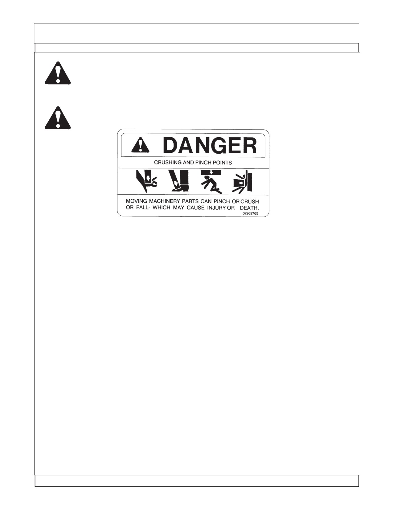
DANGER! A signal word - DANGER, WARNING, or CAUTION - is used with the Safety Alert
symbol. DANGER identifies the most serious hazards.
Maverick (NH TS-100A,115A ,125A,135A Asy. Man) 01/05
Section 2 - 2
General Information / Installation Requirements
WARNING! Safety signs with signal word WARNING are typically used to point out more
serious hazards.
CAUTION! General precautions are listed on CAUTION safety sign. CAUTION also calls
attention to safety messages in these instructions.
GENERAL INFORMATION
The tools you will need at the assembly site are as follows:
1.
Welding equipment (including correct head gear, eye shields, and protective clothing.)
2.
Impact wrench or socket and ratchet set.
3.
Rubber mallet.
4.
Box-end, Allen, and crescent wrenches.
5.
Alignment pins.
6.
Phillips and plain-head screwdrivers.
7.
Forklift or hydraulic floor jacks with rolling back boards.
8.
Over head hoist and floor jacks
9.
Jack Stands and/or other support devices that are strong enough to support tractor and
components
10.
Multidirectional Levels.
11.
Paint Scraper.
12.
Hydraulic Filter Buggy or Cart.
13.
Safety shoes, safety glasses, and gloves. A hard hat should be worn by anyone
working under any raised component.
Remember to follow each step closely and cautiously. Be aware of all support personnel at all times.
Keep the assembly area as clean as possible; clean up all spills when they occur. An uncluttered
assembly area and a crew that is sensitive to the hazards involved in putting this implement together
will help prevent accidents. Keep all unauthorized personnel from the area. Do not allow children near
the assembly site nor allow them on or near the tractor after assembly. There is no safe place for
anyone except the operator on the tractor and those assisting with the assembly.
Maverick (NH TS-100A, 115A, 125A, 135A Asy. Man) 01/05
Section 2 - 3
General Information / Installation Requirements
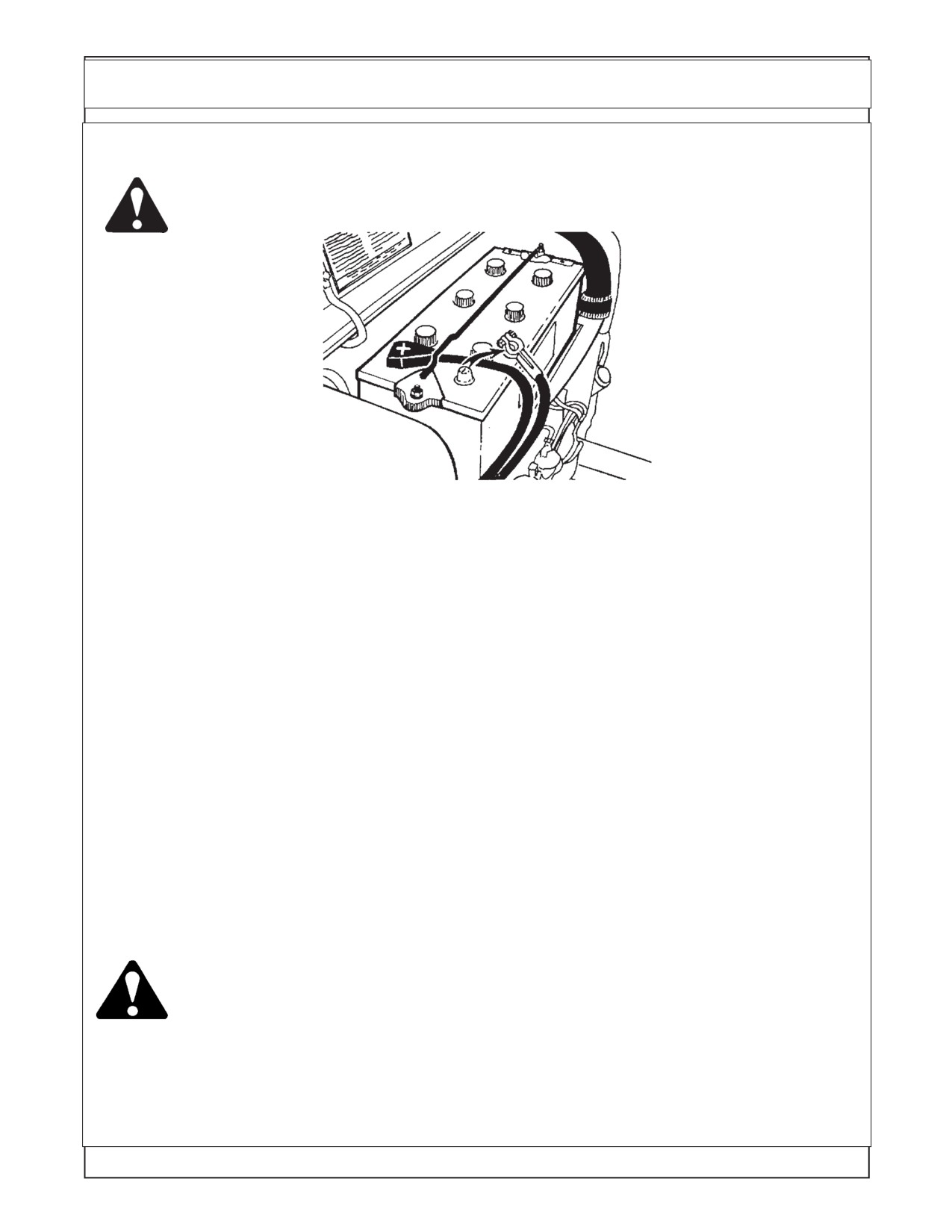
WARNING!
Disconnect the negative lead (ground) from the battery terminal to prevent any
damage to the electrical system.
LEVELING TRACTOR:
TRACTOR MUST be on level ground before assembly is begun. The tractor must be level, All tires
must have the proper amount of air in them as per tire and/or Tractors manufactures recommendations.
DO NOT level tractor by over inflating tires. The tractor can be leveled by jacking it up and putting it on
jack stands if needed.
Replacement Oil Filter
Included in the packing box of this unit is a replacement filter element for filter assembly in the tank.
This Mower unit's hydraulic components have been carefully cleaned and packaged at the factory to
prevent contamination from entering the system. However, dust and dirt particles may enter into the
sealed components through transportation, handling, rain, or just sitting in a dirty or harsh environment.
Therefore to assure that the hydraulic system is properly clean, please prepare the area where the unit
is to be assembled. The area should be on a hard concrete floor that has been swept clean of all dust
and contaminants. Unpacked the Mower unit carefully so that the seals on the hydraulic components
are not broken or pulled off.
WARNING! Before attempting to assemble the mower to the tractor, move the tractor to a clean
solid surface, preferably a concrete shop surface with an over head crane. The crane
should have a rated capacity to lift the heaviest component or assembly. A 5-ton crane
is recommended for the assembly work. If a smaller crane is used, be sure not to
exceed the rated capacity of the crane.
Q Always follow all OSHA crane operating and inspection rules, regulations,
inspection requirements, and recommended practices when using the crane.
Q Never work under any component that is lifted by the crane.
Maverick (NH TS-100A,115A ,125A,135A Asy. Man) 01/05
Section 2 - 4
General Information / Installation Requirements
WARNING!
Wear personal protective equipment when assembling the mower. As a minimum that
should include:
Q Safety Glasses
Q Safety Shoes
Q Gloves
Q Hard Hat
Q Hearing Protection
Q Welding Helmet
Before attempting to assemble ensure that the tractor engine is off and the tractor
WARNING!
transmission is in the park position with the parking brake engaged.
Q Remove the engine key and keep it in your pocket to prevent inadvertent
starting or movement of the tractor.
Q Place wheel blocks in front and behind the tractor wheels to prevent the tractor
from moving.
Q Never attempt to start the tractor unless properly seated in the tractor seat
with the seat belt fastened around you.
Q Never attempt to operate the tractor and mower controls unless seated in
the tractor seat with the seat belt fastened around you.
WARNING!
Securely block up and support the tractor before attempting to loosen and move the
tires. Failure to properly block up the tractor can result in the tractor to suddenly move
or fall, crushing you or another worker.
Q Never work under any raised component or any component that is not
securely blocked up or supported.
WARNING!
Many components of this mower are very heavy and must be handled by proper
material handling equipment. Do not lift components that weight over 50lbs by
yourself.
Q Use an overhead crane, forklift, or other coworkers to lift heavy items. Ensure
lifted components are securely supported.
Q Never walk or work under a lifted component.
WARNING!
Use extreme care when moving, handling or adjusting the tractor tires. The tires are
extremely heavy and could fall and crush you
Q Use an overhead crane or forklift to move the tires.
Q Properly fasten the tires to the material handling equipment to prevent the tire
from falling.
WARNING!
The hydraulic oil is under high pressure and a hydrauli leak can cause oil to be injected
under the skin.
Q Before starting the tractor ensure all hydraulic connections have bee tightened
Q Never check for leaks with your hands. Use a piece of wood or cardboard to
check for the leak making sure your hands and face are kept away from the
leak area.
Q Repair any leaks before operating the equipments
Q Clean up all oil that has leaked according to the requirements of the oil supplier.
Oil residue on the ground can result in unjury from slipping or falling.
Maverick (NH TS-100A, 115A, 125A, 135A Asy. Man) 01/05
Section 2 - 5
General Information / Installation Requirements
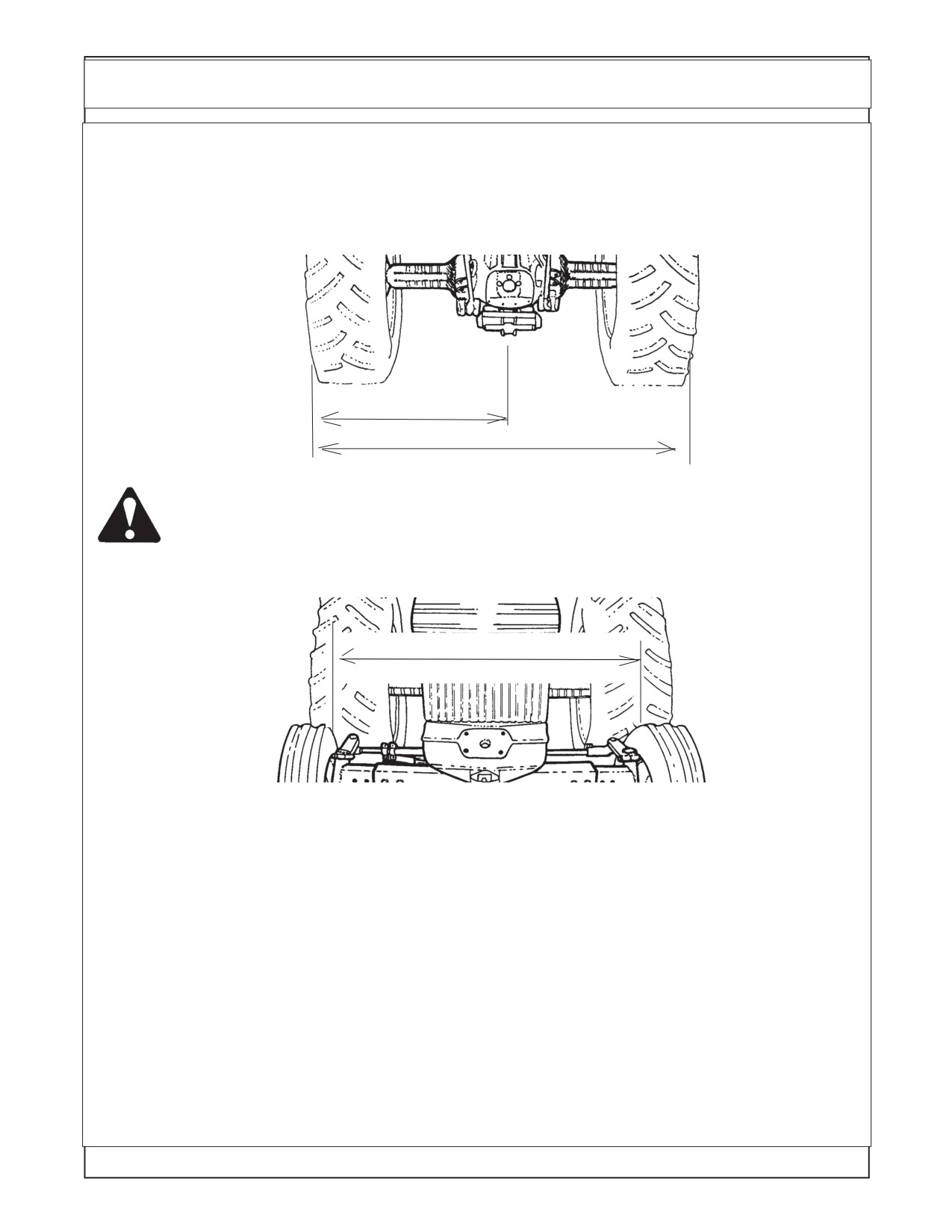
TRACTOR PREPARATION (FIGURE 1 & 2)
1. Temporally remove ROPS and fenders from tractor axle. Move left rear tire out so that it is 50 inches
from the outside of left rear tire to the center of tractor. Then move the right rear tire out so that it is 96
inches between the outside of the left and right rear tires. Refer to your tractor’s Operator’s Manual for
instructions on Rear Wheel Adjustment for your particular tire. FIGURE 1. Hydraflate rear left tire as
much as needed for stability but stay in factory-recommend limit.
FIGURE 1
50"
96"
WARNING: Never operate the tractor with a loose wheel rim or disc. Always tighten nuts
to the specified torque and at the recommended intervals.
2. Extend front wheels out so that it is 55" inches between the inside of the tires. This will allow
no interference between tire and front mount bracket. FIGURE 2.
FIGURE 2
55"
Tractor, Area Cleanliness
The Tractor, all tools and work area must be clean of dirt and debris when assembling any hydraulic
components. DO NOT leave any hydraulic component open to the elements. DO not use any containers
for fluids that are not clean and free of any other liquids. DO NOT use rags/cloth that has lint or fuzz on
them when working on hydraulic components. Keep all hoses capped until you are ready to connect
them.
Maverick Cleaning
The Maverick Components are designed to be water resistant. But the sealing can be damaged by
Pressure Washers, Steam Cleaners, Solvents or any other harsh chemical that would be used to clean
the units components. It is important to keep all electrical connections and components sealed and dry.
When washing and cleaning this unit it should be done with a non corrosive soap and low pressure spray
of water. It is recommended that all exposed electronic components be covered and protected from
excess moisture.
Maverick (NH TS-100A,115A ,125A,135A Asy. Man) 01/05
Section 2 - 6
General Information / Installation Requirements
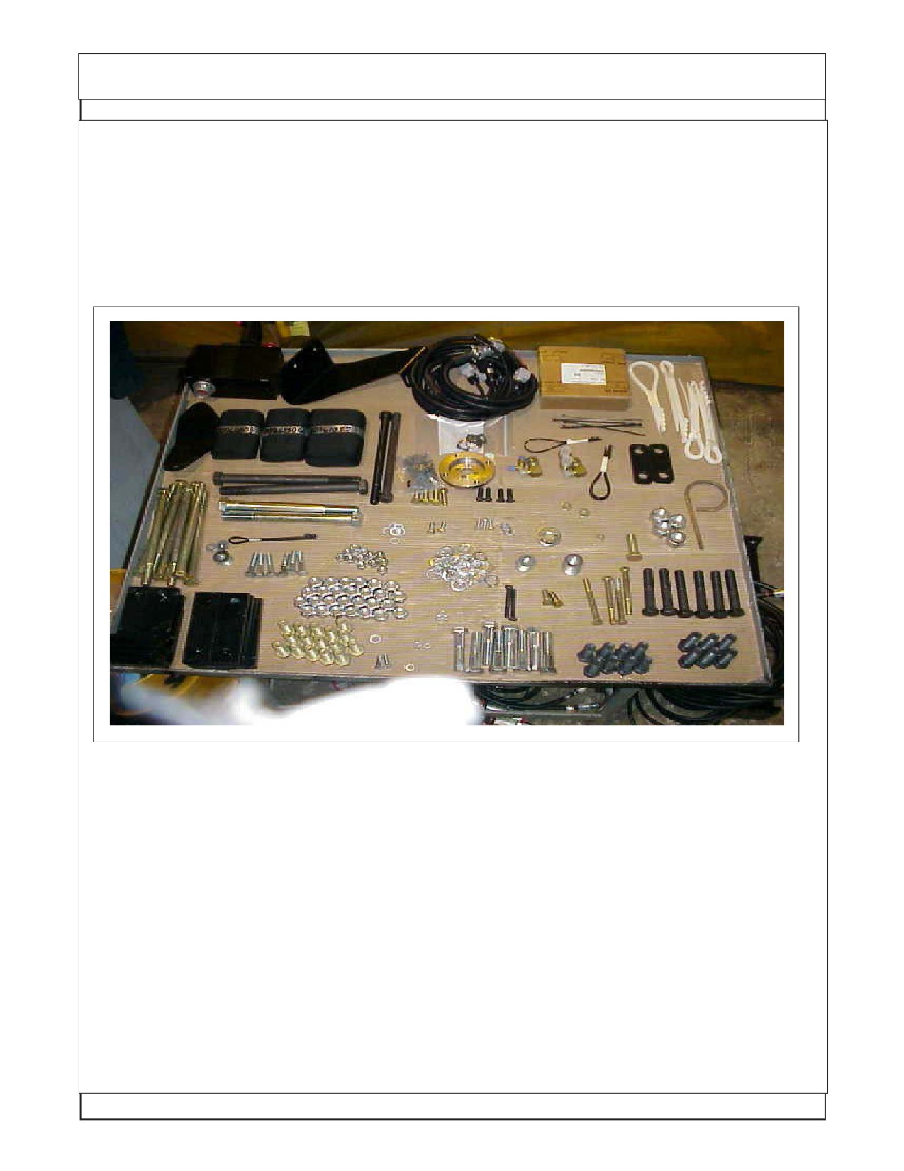
Lay Out Components in Display. It is helpful to lay out the component in as neat a display
as possible. Lay out the Bolts according to size and length. Lay out the Nuts and washer by size. This
will allow you to see how many of each part as you use them and help to identify any missing parts. (See
figure 6) See Mount Kit Specification and Component Identification Section to help ID Components.
All the component that are received should be check and sorted as to what they are.
Shown below is a general example of the components laid out, this is not a lay out of
the components in this mount kit.
WARNING
DO NOT WELD On This Unit During or After Installation:
DO NOT WELD any components or items on this unit after the installation of the
maverick Boom has begun. The Maverick Boom uses electronic modules and compo-
nents that could be damaged by welding. Before doing any welding ALL ELEC-
TRONIC MODULES AND DISPLAY COMPONENTS MUST BE UNPLUGGED. Check
the Tractors Opertion, Repair, Service or any other manual from the tractor manufac-
turer of the tractor to find any special electronic or special proedures about the tractor
electronics. Taking a few minutes to check could save you from a major damage to
the electronics.
Maverick (NH TS-100A, 115A, 125A, 135A Asy. Man) 01/05
Section 2 - 7
NOTES
Maverick (NH TS-100A,115A ,125A,135A Asy. Man) 01/05
Section 2 - 8
Section 3
MAVERICK
New Holland Tractor
TS-100A,115A,125A & 135A
Pump & Driveshaft
Installation
Maverick (NH TS-100A,115A,125A,,135A Asy. Man) 01/05
Section 3 - 1
Pump / Drive Assembly Instructions
Installing Pump, Pump Drive Components and Hydraulic Tank:
This Section covers the installation of Pump Drive Components, Pump Assembly and the
Hydraulic Tank. Some precautions must be followed during the Assembly Process and before unit is
ever started for the first time.
1.
Tractor must be disabled to prevent accidental engine start and prevent damage to components.
2.
All Fittings, Hose, Cylinders, Tank must be kept plugged at all times, No part of the Hydraulic
System can be left open at any time during mounting process, this will keep system clean.
3.
All Tools, Work Area, Components and Workers Hands must remain Clean when working on
any part of the Hydraulic System.
4.
All components should be rechecked for tightness at least twice, Hose routing also double
checked.
Preparing Tractor Front Plate (Bolster) to Slide Driveline in From Engine
Side :
1.
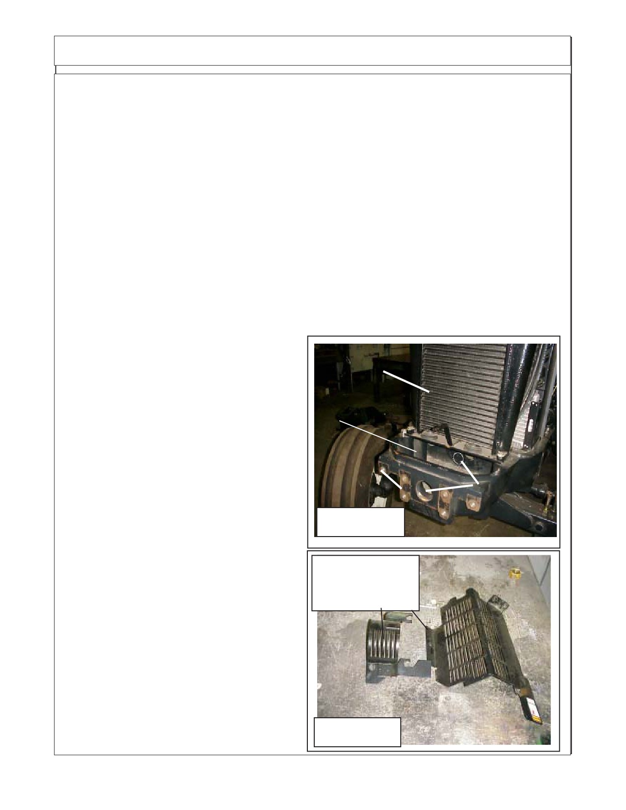
Preparing Tractor, On the Left side of Tractor there are some engine protective shields that will
have to be removed to install pulley adapter and driveshaft half (See Figure 2). The shaft half of driveline
will have to be slid down and through the bolster from the engine side of radiator. The driveshaft has
to slide in from the engine side because the hole (2 holes) in bolster are to small for driveline flange yoke
to slide through. There is a plate that is bolted under the After Cooler that will have to be removed
to gain access to inner hole, when the four bolts
that retain after-cooler are removed the plate will
slide out. While this plate is out check the hoses for
Air After-Cooler
the Oil Cooler and Air Conditioning condenser,
these hoses need to be tied up in such away that
they will not rub on driveshaft after it has is installed.
Cover removed
Installing Pump Drive Components:
1.
With Front Bolster as shown (See Figure
1), Remove any plastic plugs that are located in the
threaded holes in the front and discard them, they
Tractor
Existing Holes
will not be needed. The Casting will have two
Bolster
have rubber
Driveline Hole in it. (See Figure 1).
Plugs in them
Installing Pulley Adapter:
1.
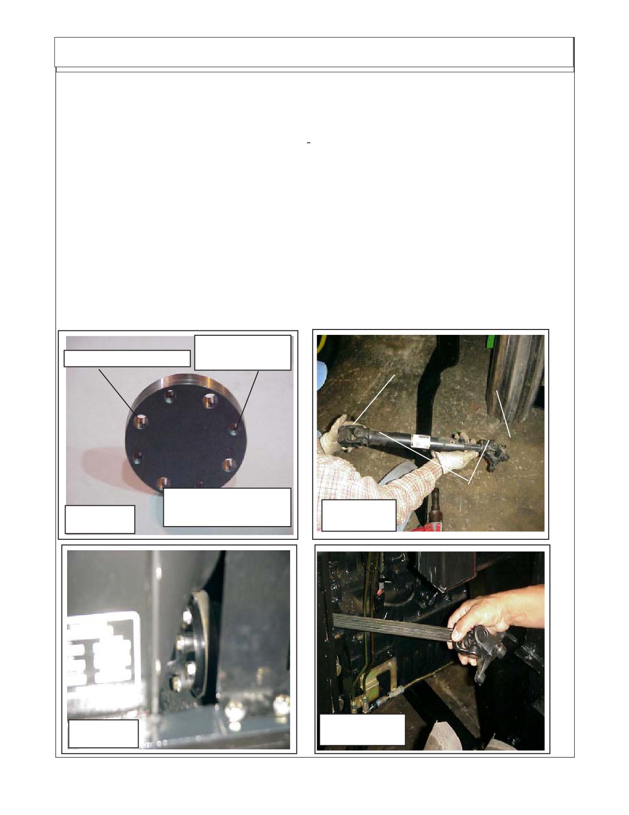
Install Pulley Adapter. The Pulley adapter
Figure 1
(P/N 02980699) is a round plate with 4 threaded
holes and four non-threaded holes in it. Notice this
pulley adapter will not have a center hole in it (See
LH Side Engine
Figure 3). The four non-threaded holes are used
Guards Removed
to mount the Adapter to the Crankshaft Pulley
From Tractor
using bolts (P/N 02980967) 12 mm X 60 mm long
and lockwashers (P/N 00754566) 12 mm that are
supplied in mount kit. The four threaded holes are
used to install the flange yoke of driveline to pulley
adapter Do not use longer bolts to mount Pulley
Adapter to Pulley or Flange yoke to adapter than
are supplied with mounting kit, if longer bolts are
used they could go through adapter and pulley
causing damage. Tighten the four bolts that retain
the pulley adapter to the pulley now, it will be easier
than trying to tighten them later. (See Figure 3 & 3A)
Figure 2
Maverick (NH TS-100A,115A,125A, 135A Asy. Man) 01/05
Section 3 - 2
Pump / Drive Assembly Instructions
2.
Install Shaft Half of Driveline with Flange Yoke. Note the driveline universal joints should be timed
(See Figure 4). Slide the two driveline half assemblies apart and lay the tube half aside for now. Make
certain that the four retaining bolts for the Pulley adapter to the crankshaft pulley have been tightened.
3.
Check the length of the spline shaft of the driveline is a must. The shaft should be 12-1/
2" long (Measure Shaft Only). on some drivelines this shaft will have to be cut. The correct way to cut
this shaft is with a saw, after cutting use a file & grinder to chamfer the cut end and clean the splines.
DO NOT cut shaft with a Torch as this will change the hardness of the shaft.
4.
From the side of the tractor (LH side) slide the Shaft Half of driveline shaft end first down into the
opening below the radiator from engine side, insert it through the existing hole and/or cut hole
combination until the shaft is pointed toward the front of the tractor, and the flange yoke is over far enough
to align with the four threaded pulley adapter holes.
5.
Align the four holes in the flange yoke of driveline with the four threaded holes in the pulley adapter.
Install the four retaining 7/16" X 1-1/4" long bolts (P/N 02976344) and 7/16" lockwasher (P/N 00022200)
into flange yoke into adapter, tighten them at this time. These four bolts can be tightened by using a
long socket extension run through along side the driveline shaft.
6.
Set the tube end of driveshaft aside for now as it will be installed later. But always remember the
driveline universal joint must be aligned (timed) when assembling the driveline halves.
4 Threaded
Splined Clamp Yoke
Holes
4 Non-Threaded Holes
/ Tube End
Flange Yoke
/ Shaft End
Drive Shaft
Pulley Adapter
Assembly
P/N 02980699
Figure 4
Figure 3
Figure 4A
Figure 3A
Maverick (NH TS-100A,115A,125A,,135A Asy. Man) 01/05
Section 3 - 3
Pump / Drive Assembly Instructions
Install Tank Rail Weldments:
123
123
1223
1
12
123
1223
123
1223
1.
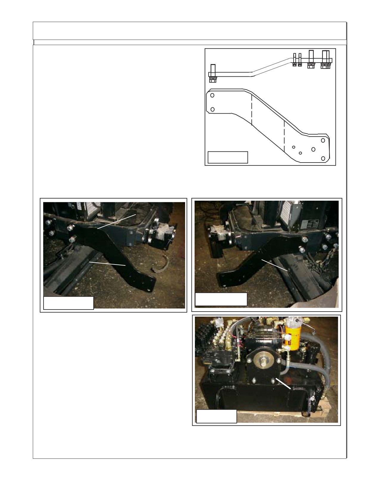
Install Tank Rail Welments. P/N 02981405 LH
123
123
and P/N 02981404 RH. These will bolt on using the two
123
123
holes to the front of the frame rail supports. This will need
RH Side Shown,
Tractor
to be done so the hydraulic tank can be mounted.
tighten these two bolts (two each side) now. NOTE:
There is a left hand and a right hand weldment, the best
way to determine which is LH and RH is theway they fit.
The bend is bolted on to make the distance between the
two tank rails the same as the width of the hyd tank.
Installing Pump Mntg Weldment :
1.
Install Pump Mounting Weldment. The Pump
Mount Weldment (P/N 02980719) bolts to the front
Figure 5
of the tractor bolster using four 20 mm X 45 mm long
bolts (P/N 02975959) and 20 mm lockwashers (P/N 02971158) . Install the Pump Mounting
Weldment (P/N 02980719) with the opening for the driveline cover up. Tighten the four mounting
bolts now. (See Figure 8)
Bolt on Cover on
RH Tank Rail
LH Tank Rail
Figure 7
Figure 6
2.
Remove Bolt on Cover In front of After Cooler.
This is an important step. The Air Conditioner Hoses
and the Oil Cooler Hoses are under this cover (See
Figure 6 & 11). These hoses must be tied and routed
so the driveshaft will not rub them when engine is
running. The hose can be tied with a sturdy plastic
tie or other means sufficient to hold the hoses away
from driveshaft.
3.
Remove Pump Shipping Bracket. The pump
Pump Shipping
is shipped using a bracket that bolts to the pum and
Bracket
the tank assembly. Before pump can be installed it
Figure 8
will have to be unbolted from pump and tank. The
shipping bracket is for shipping only and will not be
used. When unbolting pump from tank assembly there are hoses that will have to be disconnected from
pump as tank to pump hoses (filters are connected when assembly is shipped. Caution must be taken
when disconnecting these fittings and/or hoses to keep the capped to keep contamination out of them.
Maverick (NH TS-100A,115A,125A, 135A Asy. Man) 01/05
Section 3 - 4
Pump / Drive Assembly Instructions
Installing Driveline Half to Pump :
1.
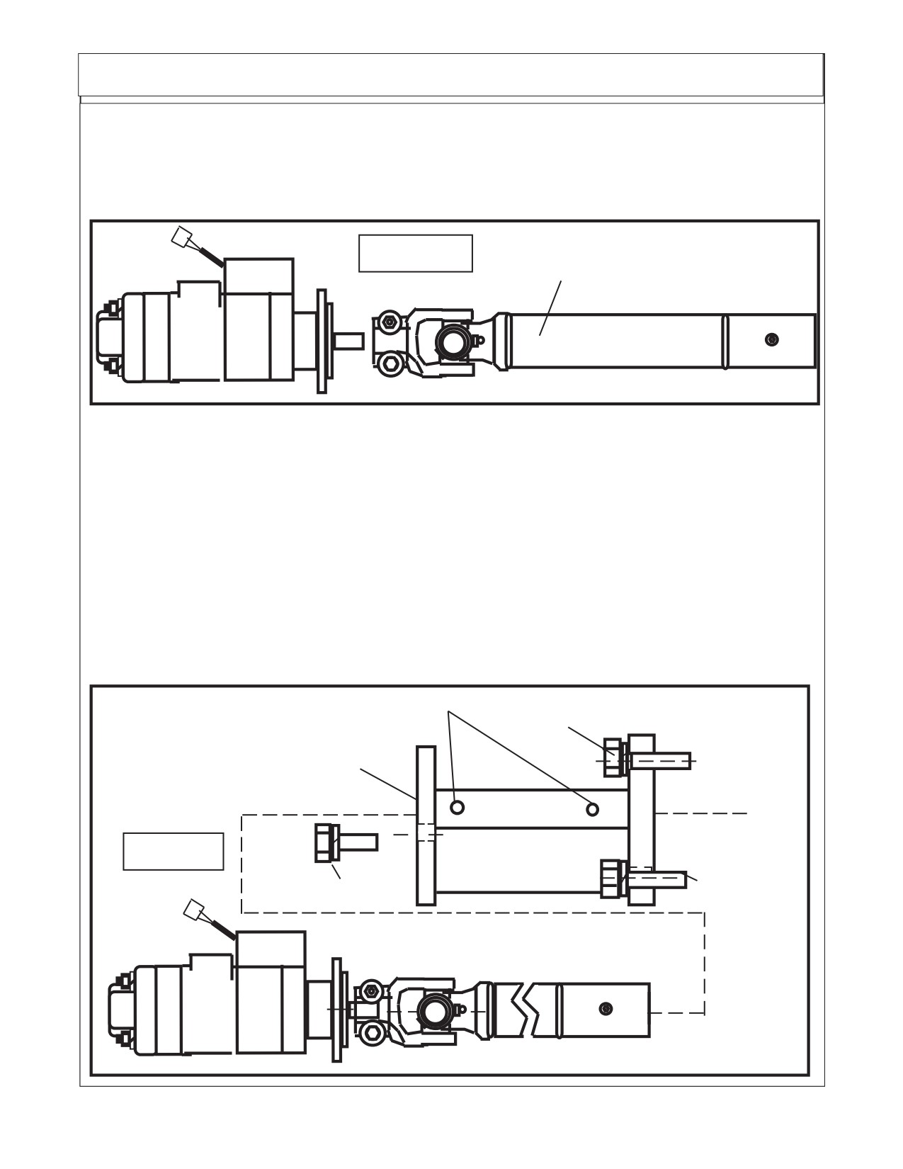
Install Driveline Half to Pump. Install the clamp yoke of the tube half of driveline onto the
pump, slide the clamp yoke on pump shaft until you have about 1/8" to 1/4" gap between yoke
and pump. Do not install yoke so far on pump shaft that yoke will rub against pump in anyway.
Tighten the two bolts and nuts on clamp yoke at this time. (See Figure 9 & 14)
Driveline Tube Half with
Figure 9
Clamp Yoke
1
12
12
12
12
123456
12
12
123456
12
12
123456
12
12
12
12
1
12
12
Installing Pump to Pump Mount Weldment :
1.
Install Pump to Pump Mount Weldment. The Pump has the tube half of driveline attached
and clamp yoke tightened. To install the pump and driveline half it is best to use an assistant or
overhead hoist to help you align the drivelines halves as they are slid together, the Driveline must
be timed (universal joints aligned the same) as shown in the pump & driveline schematic on (See
Figure 10 thru 17). Slide Driveline half and pump together until the shoulder on the pump slide
in the hole on the pump mount weldment.
When installing the pump always keep ports sealed to keep them clean and free of
contamination. The pump MUST be turned correctly. This can be done by making certain that the
pressure filter that is mounted on top of the pump is up.
Install the two 1/2" X 1-1/2" long pump mount bolts (P/N 02892000) and two 1/2"
lockwashers (P/N 00001300). Tighten the two pump mounting bolts.
Install Pump Driveline cover here
Mounting Bolts
12345678901
P/N 02980666 Pump
12345678901
12345678901
Mount Weldment
123456789
Bolts To
123456789
123456789
Figure 10
Tractor Bolster
123456789012
123456789012
123456789012 M
ounting Bolts
Pump Mntg Bolts
1
12
12
12
12
12
1234
12
12
12
12
12
12
12
Maverick (NH TS-100A,115A,125A,,135A Asy. Man) 01/05
Section 3 - 5
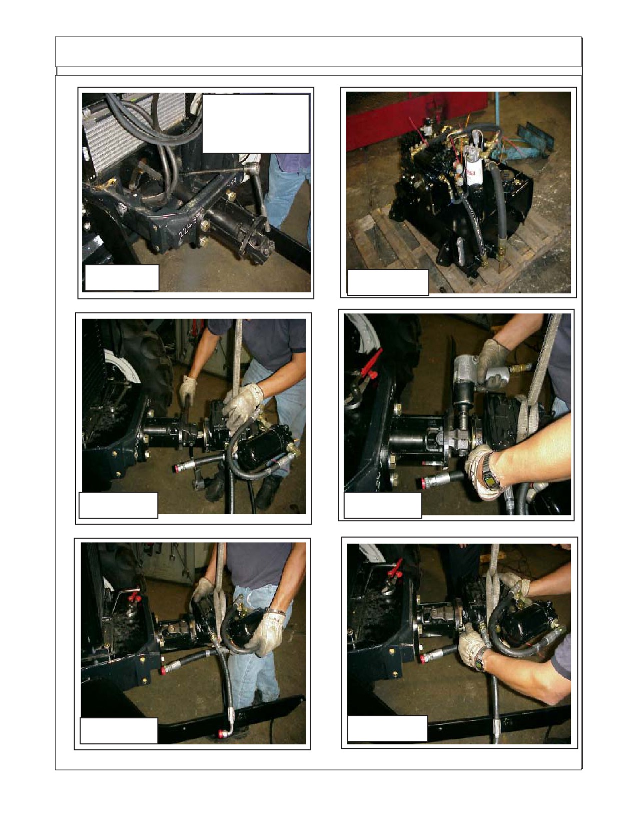
Pump / Drive Assembly Instructions
Driveshaft & Pump
Pump Shipped w/ Hyd. Tank, Valve
Mount Weldment
is bolted to Tank
installed
Figure 11
Figure 12
Tighten Clamp Yoke, leave
Align Splines on Pump Shaft
1/8" to 1/4" gap btween
with Driveshaft clamp yoke.
yoke & pump
Figure 13
Figure 14
Push Pump into Pump
Install Pump
Mount until flush
Mounting Bolts
Figure 16
Figure 15
Maverick (NH TS-100A,115A,125A, 135A Asy. Man) 01/05
Section 3 - 6
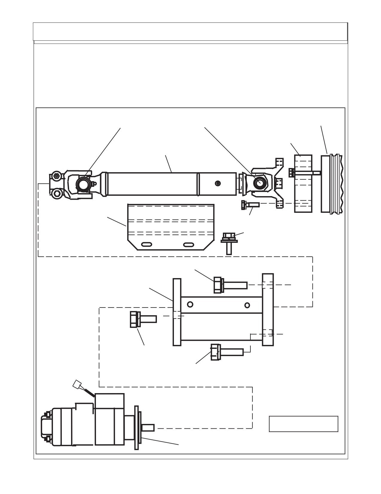
Pump / Drive Assembly Instructions
Installing Pump Driveline Cover :
1.
Install Pump Driveline Cover. The Pump Driveline will have a cover (P/N 02980398) which
retained by four 1/4" X 3/4" bolts (P/N 00021400), four 1/4" flatwashers (P/N 00024100) and four
1/4" lockwashers (P/N 00017000), install and tighten these now (See Figure 6).
Tractor Engine Pulley
Time Universal Joints
Pulley Adpater w/ Mounting
Pump End
Bolts & Washers (4 bolts)
Clamp Yoke
Driveline Asy
1
12
1234
1
12
1
12
1
12
1
12
1
12
1
12
12345
P/N 02980398
4 Driveline Mounting Bolts
Driveline Cover
Driveline Cover Mounting Bolts,
123
Flatwashers & Lockwashers (4)
123
123
123
123
Mounting Bolts
23456789012
P/N 02980666 Pump
23456789012
23456789012
Mount Weldment
123456789
123456789
123456789
Bolts To
Tractor Bolster
12345678901
Pump Mounting
12345678901
12345678901
Bolts
Mounting Bolts
1234
Figure 17
Pump (Reference)
Maverick (NH TS-100A,115A,125A,,135A Asy. Man) 01/05
Section 3 - 7
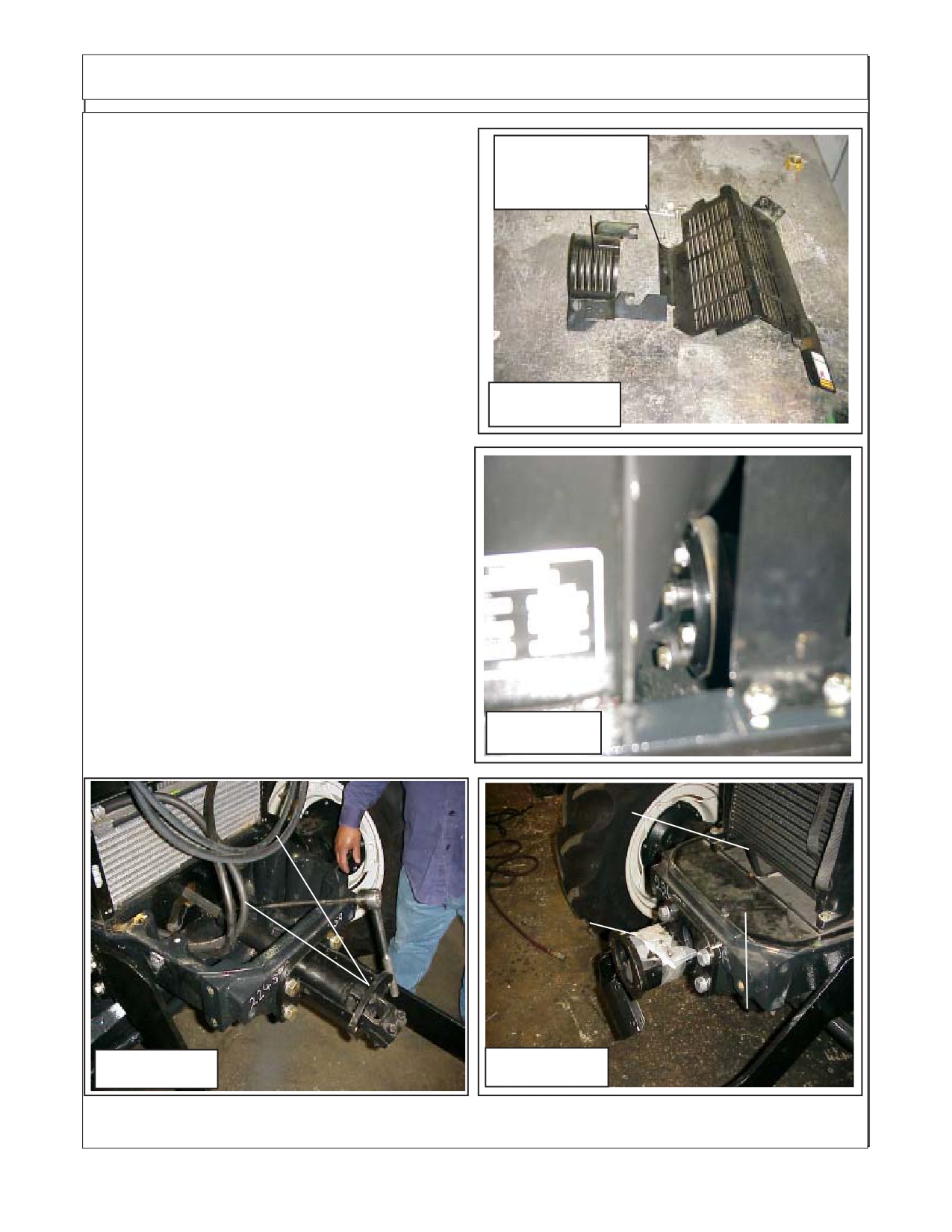
Pump / Drive Assembly Instructions
Install Tractor Guards & Covers:
LH Side Engine
Guards Removed
1.
Reinstall LH Side Engine Guards. The left
From Tractor
hand side engine guards need to be reinstalled
using the original hardware (See Figure 18). These
guard are to gain access so the pulley adapter
could have been installed as shown (See Figure
19).
2.
Reinstall Top Cover. There is a top cover
that bolts onto the front of the tractor that is
removed to make certain that the hoses that run
underneath (See Figure 20) are tied back to
prevent them from rubbing on the driveshaft that
Figure 18
was installed, this is very important to prevent
damage to the hoses (See Figure 21). The front
cover plate will be installed using the original
hardware.
3.
Install Pump Mount Driveshaft Cover. The
Pump Mount has a bolt on cover on top of it (See
Figure 17 & 21). The cover and bolts are furnished
with kit. In figure 21 is shown without pump in-
stalled, this is for illustration only. Do not install
cover before pump is installed.
4.
Review this section and make certain all
components are installed and tightened to speci-
fication (Bolt Toque Chart) and hoses are se-
cured so as not to interfere with another compo-
Figure 19
nent.
Air Conditioner &
Oil Cooler Hoses
Pump
Mount
Cover Bolts
Here
Air Conditioner &
Oil Cooler Hoses
Front Cover
Figure 20
Figure 21
Maverick (NH TS-100A,115A,125A, 135A Asy. Man) 01/05
Section 3 - 8
Section 4
MAVERICK
New Holland Tractor
TS-100A, 115A, 125A, 135A
Hydraulic Tank &
Control Valve
Installation
Maverick (NH TS-100A,115A , 125A, 135A Asy. Manl) 01/05
Section 4 - 1
Hydraulic Tank & Control Valve Installation
Hydraulic Tank and Control Valve installation:
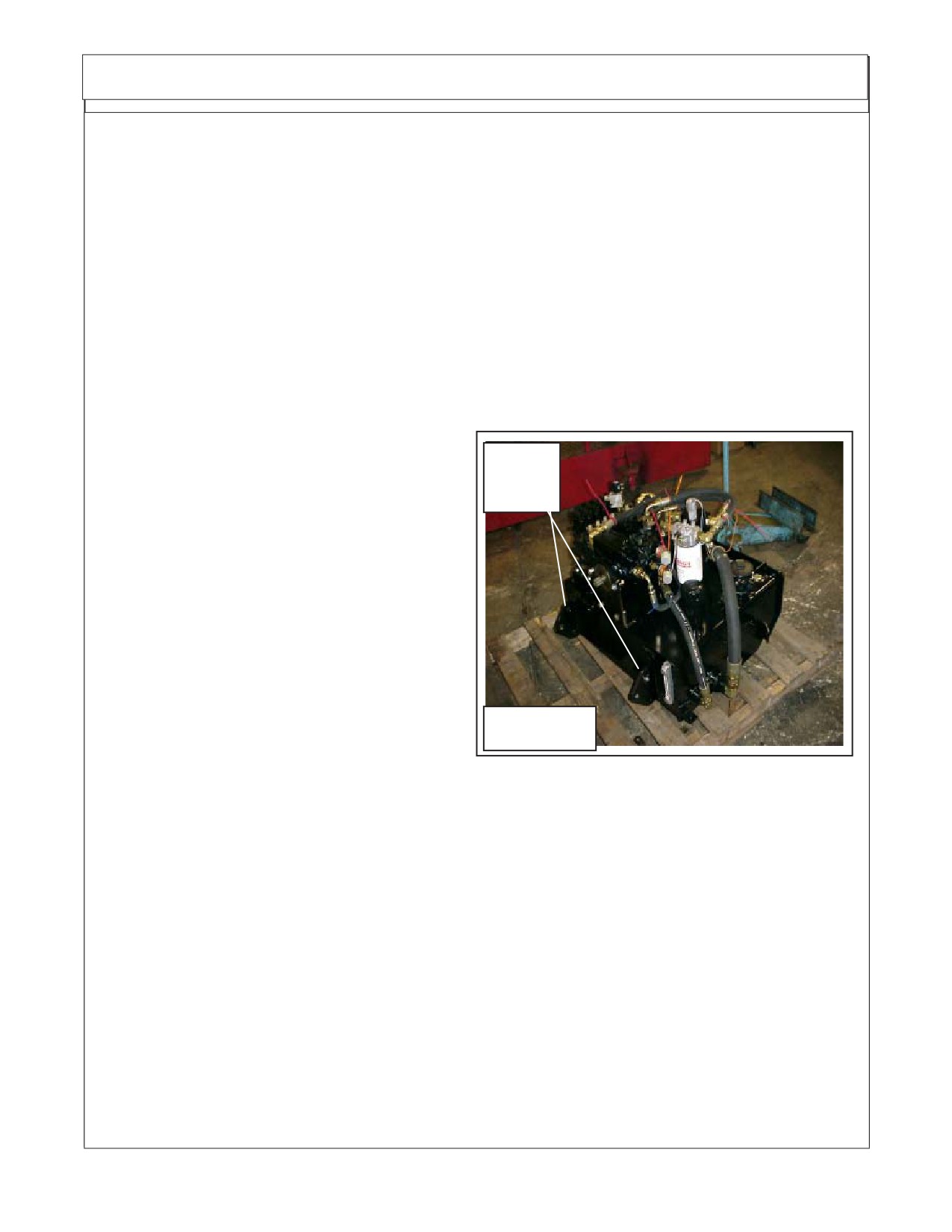
This Section covers the installation of the Hydraulic Tank and Control Valve Assembly. The Tank
and valve are shipped as an assembly.
1. Locate Tank and Valve Asy, this will need to be lifted with a hoist, the front bumper wldmnt
is welded to the front of the tank from the factory.
2. All Tools, Work Area, Components and Workers Hands must remain Clean when working on any
part of the Hydraulic System. All hoses and fittings should remain plugged till ready to install them
to keep them clean.
3. All components should be rechecked for tightness and Hose routing also double checked.
Install Hydraulic Tank to Front of Tractor:
1.
Hydraulic Tank and Valve Assembly, The Hydraulic Tank, Control Valve and Pump are shipped
together (See Figure 1). The Pump should have already been mounted.
2.
Install Hyd. Tank & Control Valve Asy. To
install the tank and valve assembly you should
Inner
use an over head hoist to lift Tank and Valve
Mounting
Assembly, as it is heavy and can be damaged if
Tabs
dropped. The hoist will also assist when aligning
the mounting holes. There are three mounting
tabs in the rear of the tank. Mount the three rear
bolts, Three on each side. The hydraulic tank
slide under pump and between the LH & RH Tank
rails. Do not remove from hoist until tank has been
bolted on and bolts tightened
3.
Rotate Fittings to make better access to
Valve and tank connections, The fittings in the
pump and valve may have to be rotated to make
Figure 1
it more accessable whenconnecting the hoses.
Hose Connections To Pump And Hyd Tank: (See Figure 2)
Item Part No.
Qty. Description
A
02981427
1
Hose, 8FJX - 8FJX 90° - 24" Lg. w/Red Tie (Charge Filter to Pump)
B
02981428
1
Hose, 8FJX - 8FJX 90° - 21" Lg. w/ Blu Tie (Case Drain to Tank)
C
02981429
1
Hose, 12FJX - 12FJX - 23" Lg. (Pump to Suction Filter) hose under
pump and cannot be seen in drawing.
D
02981430
1
Hose, 12FJX - 12FJX - 31" Lg. w/ Red Tie (Pressure Filter to Supply)
E
02981431
1
Hose, 4FJX - 4FJX 90° - 35" Lg. w/ Red Tie (Pump Load Sense to Valve (PX)
Connects to top side of pump as shown.
F
02981432
1
Hose, 4FJX - 4FJX 90° - 20" Lg. w/ Blu Tie (Pump Regulator to Tank)
Connects to bottom side of pump not seen.
F
-------------
1
Hose #4, Connects here w/ Tee Fitting (Connect to Base End Stabilizer Cyl)
G
02981433
1
Hose, 20FJX - 12FJX - 24" Lg. (Pump to Suction Filter)
H
02981462
1
Hose, 12FJX - 12FJX 90° - 20" Lg. w/ Org Tie (Valve Return to Tank)
J
-------------
1
Hose, # 16 w/ Red Tie (Pressure from Pump to Motor) Bottom Port
K
-------------
1
Hose, # 16 w/ Orange Tie (Oil Return from Motor) Top Port
L
-------------
1
Hose. w/ Blue Tie (Oil Return from Oil Cooler to Tank)
Maverick (NH TS-100A,115A, 125A, 135A Asy. Man) 01/05
Section 4 - 2
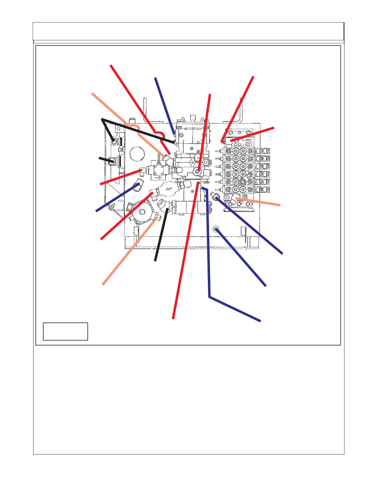
Hydraulic Tank Hose Routing
"J" # 16 Hose
"B" # 8 Hose
(Red Plastic Tie)
(90° Elbow)
"E" # 4 Hose
(Blue Plastic Tie) "A" # 8 Hose
(Red Plastic Tie)
"K" # 16 Hose
(90° Elbow)
(Orange Plastic Tie)
(Red Plastic Tie)
"C" # 12 Hose
Suction Hose
"D" # 12 Hose
(No Plastic Tie)
(Red Plastic Tie)
"G" # 20 Hose
Suction Hose
(No Plastic Tie)
"A" # 8 Hose
(Red Plastic Tie)
"H" # 12 Hose
"L" # Hose
(90° Elbow)
(Blue Plastic Tie)
(Orange Plastic Tie)
"D" # 12 Hose
(Red Plastic Tie)
"B" # 8 Hose
(Blue Plastic Tie)
"G" # 20 Hose
Suction Hose
(No Plastic Tie)
"F" # 4 Hose & Tee
"H" # 12 Hose
Tank Return
(Orange Plastic Tie)
(Blue Plastic Tie)
"F" # 4 Hose
"E" # 4 Hose (90° Elbow)
(90° Elbow)
Figure 2
(Red Plastic Tie)
(Blue Plastic Tie)
NOTE: Hoses are not shown in drawing above, this is for clarity. The hose routing is for the hoses which
connect from one point to the other. Use the instructions and hose description listed to follow hose
routing.
Example: Hose - A connects to one end marked A and the other end of hose connects to the other item
marked A. This is done with the other letters as well, the hose must connect to the same letter markings
on each end as in drawing. Some hose will be marked with a colored plastic tie.
Some hose will have a straight fitting or a 90° fitting. This is to allow hoses to be routed to where they
clear other items, when connecting hose put the end on that has the correct fitting as noted in drawing
with (90°) or the straight fitting if note marked hose routing that is to make hoses clear other items. Do
Not connect hose to different letter items, all hose end must connect to the same letter on both ends.
TO ID HOSES: Always check Size, Length, Fittings and Color Plastic Tie to identify the hoses. Some
hoses will have the same color tie but the size, length or fittings will be different.
Maverick (NH TS-100A,115A , 125A, 135A Asy. Manl) 01/05
Section 4 - 3
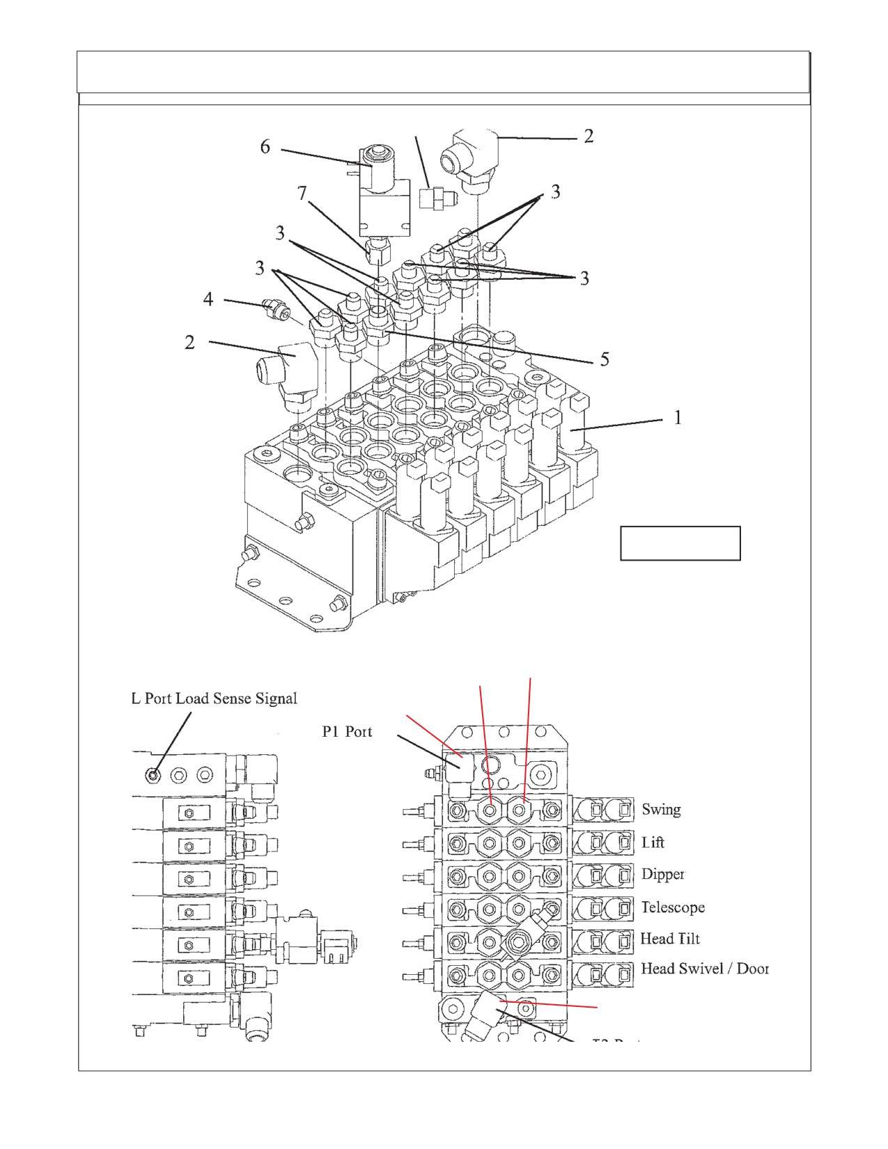
Directional Control Valve Fittings
FIGURE 3
"A"
"B"
Ports Ports
Pump Pressure
Port
Tank Return Port
Maverick (NH TS-100A,115A, 125A, 135A Asy. Man) 01/05
Section 4 - 4
Directional Control Valve Fittings
Valve Fittings and Location: (See Figure 3)
Item Part No.
Qty Description
02981888
--
Valve & Fittings Asy, 6 Spool
1
02981370
1
Valve Asy w/o Fittings
2
02090800
2
Adapter Hyd, Elbow 12MB - 12MJ 90°
3
02972177
11
Adapter Hyd, Straight 10MB - 6MJ
4
03200284
1
Adapter Hyd, Straight 6MB - 4MJ
5
02981889
1
Adapter Hyd, Straight 10MB - 6MJ
6
02972208
1
Valve Solenoid Asy
7
02975438
1
Adapter Hyd, Straight 8MB - 8FJX
8
02981890
1
Adapter Hyd, Straight 8MB - 6MJ
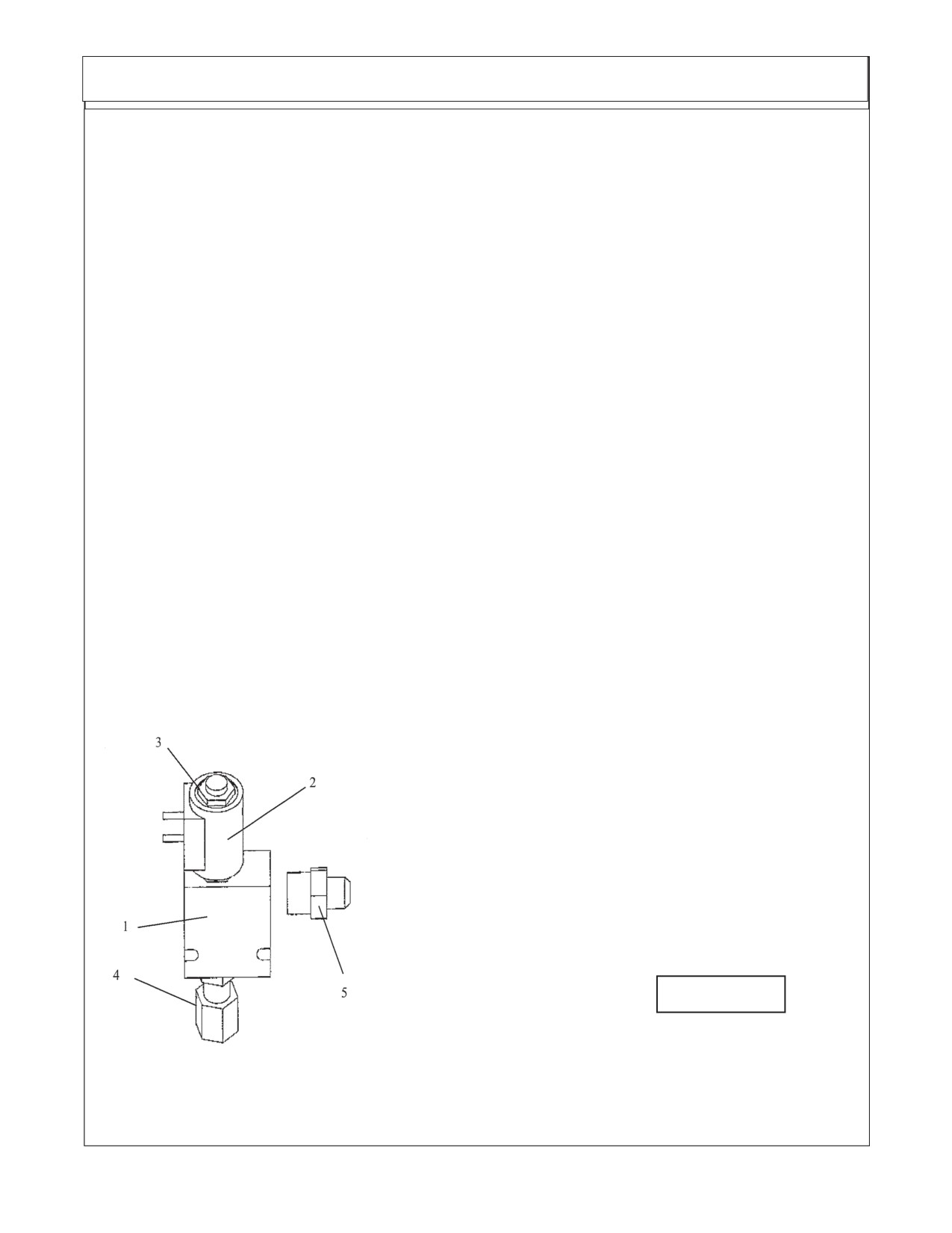
HYDRAULIC LOCK VALVE: (Head Tilt Function)
An Electric Solenoid Operated Hydraulic Lock Valve (Figure 4) is incorporated in the Head Tilt
Function to prevent excessive (Head Lift Cylinder) leak down during storage or transportation.
The Solenoid which operates this valve is normally in the Locked position until Head Lowering
function is actuated at Joystick. When Joystick is actuated to lower Head an electric signal
is sent to solenoid to open Lock valve. When the function to raise the Head is activated there
is no electric signal from Joystick. The pressure against the valve when head is being raised
will force Valve open like a relief Valve allowing Oil to pass through it. If this valve will not open
it could stop head from lifting or dropping. The valve is plumbed into the Hydraulic Circuitry of
the Head Tilt Function and is located near the Control Valve.
Hydraulic Lock Valve
Item Part No.
Qty.
Description
02972208
--
Solenoid Valve Asy
1
02971425
1
Seal Kit, f/ solenoid Valve
2
02975198
1
Coil, 12V- DC w/Dual
8-32NF Studs
3
02975199
1
Cartridge, Solenoid Valve
4
02975438
1
Adapter Hyd, Straight 8MB-6FJX
5
02981890
1
Adapter Hyd, Straight 5MB - 6MJ
FIGURE 4
Maverick (NH TS-100A,115A , 125A, 135A Asy. Manl) 01/05
Section 4 - 5
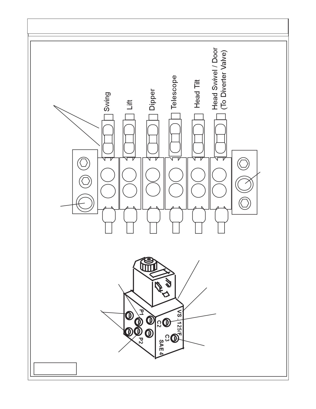
Hydraulic Hose Connections
HYDRAULIC HOSE CODES AT VALVE
Hydraulic Hose Band Mark Color Codes: Hose's and/or fittings are marked with a
Color Coded Plastic Band around it. Some Bands are a solid Color and some are Colored with a
Stripe. The purpose of the colored bands are to provide a quick reference for hose and port
connection. A metal band is also attached to the hose, on that band is an Alamo Industrial Part
Number for reference if needing a replacement hose. Always Check Hose Size, Color Code
& Part Number
(See Figure 5)
Boom Cylinder Circuit Hoses:
Color Tie
(Code) Hose Size Port Diverter Hyd. Function
Green
G
SAE # 6
A
---
Swing, Back (Rod End)
Green / White
G/W
SAE # 6
B
---
Swing, Forward (Base End)
Orange
OR
SAE # 6
A
---
Lift, Down (Rod End)
Orange / White
OR/W
SAE # 6
B
---
Lift, Up (Base End)
Blue
B
SAE # 6
A
---
Dipper, In (Rod End)
Blue / White
B/W
SAE # 6
B
---
Dipper, Out (Base End)
Yellow
Y
SAE # 6
A
---
Telescope, In (Rod End)
Yellow / White
Y/W
SAE # 6
B
---
Telescope, Out (Base End)
Red
R
SAE # 6
B
---
Head Tilt, Up (Rod End)
Red / White
R/W
SAE # 6
A
---
Head Tilt, Down (Base End)
Green
G
SAE # 4
A
P2
Control Valve tor Diverter valve
Green / White
G/W
SAE #4
B
P1
Control Valve to Diverter Valve
Green
G
SAE # 4
---
C4
Swivel, CW (Rod End)
Green / White
G/W
SAE # 4
---
C1
Swivel, CCW (Base End)
Yellow
Y
SAE # 4
---
C3
Door, Open (Rod End)
Yellow / White
Y/W
SAE # 4
--
C2
Door, Closed (Base End)
Orange
OR
SAE#12
T
---
Valve Return To Tank
Red
R
SAE#12
P
--
Pressure to Valve.
Motor Circuit Hoses to Boom Connections: (Listed as reference)
Color Tie
(Code) Hose Size
Hyd. Function
Red
R
SAE # 16
--
Pressure Flow to Motor
Orange
OR
SAE # 16
--
Return Flow From Motor
Blue
B
SAE # 8
--
Case Flow From Motor to Boom
Blue
B
SAE # 12
--
Case Flow at Boom to Tank
Diverter Valve.:
The Diverter Valve bolts onto the front frame mount bracket on the LH side of the tractor, the holes
are in the bracket (See Figure 5 , 6 & 7). The Diverter valve is a electrical operated valve that allows the
hydraulic pressure to be shared to operate two (or more if valves are stacked) functions with a single
pressure supply. This valve is strictly a diverter valve and is designed to direct the pressure, not regulate
the flow or pressure.
The Port openings on this diverter valve are marked with letter number codes which show which
port is connected to which hose and where that hose connect on other end (See Figure 5, 4 & 7))
Port
Function & Connection
P1
Hose Hydraulic Pressure from Door / Swivel (B) Port on Control Valve (G/W Tie)
P2
Hose Hydraulic Return to Door / Swivel (A) Port on Control Valve (G Tie)
C1
Hose to Head Swivel Cylinder Base End (G/W Tie)
C2
Hose to Door Cylinder Base End (Y/W Tie)
C3
Hose to Door Cylinder Rod End (Y Tie)
C4
Hose to Head Swivel Cylinder Rod End (G Tie)
Maverick (NH TS-100A,115A, 125A, 135A Asy. Man) 01/05
Section 4 - 6
Hydraulic Hose Connections
Six Spool Control Valve
External Wire Connec-
tions for valve are marked
"A" and "B" on Valve &
AA1 thru AA12 on wire
harness connections
B
B
B
B
B
B
AA
AA
AA
AA
AA
AA
12
10
8
6
4
1
AA
AA
AA
AA
AA
AA
11
9
7
5
3
2
A
A
A
A
A
A
"B"
"B"
"B"
"B"
"B"
"B"
OR/
Return
Y/W
R
G/W
G/W
B/W
W
To Tank
"T"
B
Y
R/W
G
G
OR
Pressure
"A"
"A"
"A"
"A"
"A"
"A"
Supply
Port "P"
Diverter Valve
Diverter Valve "C1" Port
to Swivel Cyl Base
End Port (G/W Tie)
Valve "B" Port to
Diverter valve P1 Port
Diverter Valve "C4" Port
(G/W Tie)
to Swivel Cyl Rod End
Port (G Tie)
4 Through holes are
Diverter Valve "C2" Port
mounting holes
to Door Cyl Base End
Port (Y/W Tie)
Diverter Valve "C3" Port
Valve "A" Port to
to Door Cyl Rod End
Diverter valve P2 Port
Port (Y Tie)
(G Tie)
FIGURE 5
Maverick (NH TS-100A,115A , 125A, 135A Asy. Manl) 01/05
Section 4 - 7
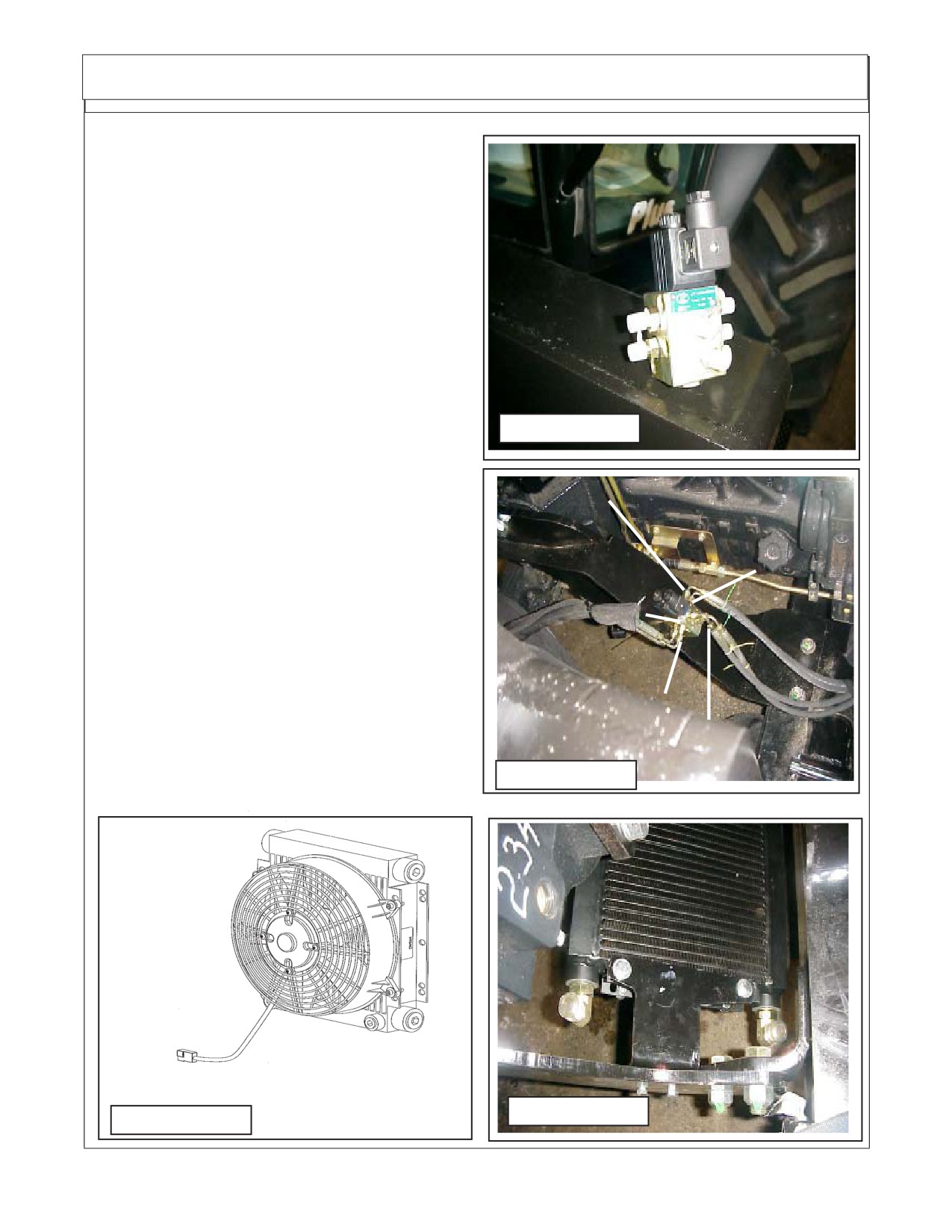
Oil Cooler / Fan Assembly
Connecting Oil Cooler And Fan As-
sembly to Exterior Wire Harness
1.
Oil Cooler / Fan Assembly. The Oil
cooler / fan assembly is for cooling the oil
being returned from the Motor Case Drain.
The fan is connected to the control box and is
turned on & off automatically. It set to run on a
Diverter Valve
program that will run the fan in the cooling
rotation for a designated time, then stop, re-
verse the rotation (cycle to clean debris off of
cooler, then stop and reverse the fan again
and begin the cycle all over again.
The connection to the cooler on the
FIGURE 6
exterior wire harness is marked with code R1.
The connection from the fan will have two
wires, a Blue (+ connection) and a black (-
Swivel Cyl. Base End C1 Port (G/W Tie)
connection) (See Figure 8).
Swivel Cyl. Rod
End C4 Port (G Tie)
From Valve "A"
Port to P1 Diverter
Door Cyl.
Port (G / WTie)
Base End
C2 Port
(Y/W Tie)
Valve "A" Port to
P2 Diverter Port
Door Cyl. Rod End
Port (G Tie)
C3 Port (Y Tie)
FIGURE 7
Exterior wire harness con-
nection marked R1 connects
here
FIGURE 9
FIGURE 8
Maverick (NH TS-100A,115A, 125A, 135A Asy. Man) 01/05
Section 4 - 8
Section 5
Maverick Boom
New Holland Tractor
TS-100A,115A,125A & 135A
Battery Modification
Exhaust Modification
Fuel Tank Modification
Main Frame Installation
Maverick (NH TS-100A,115A,125A,135A Asy. Man) 01/05
Section 5 - 1
//////////////////////////////////////////