New Holland CX720, CX740, CX760, CX780, CX820, CX840, CX860, CX880. Operator's Manual - page 15
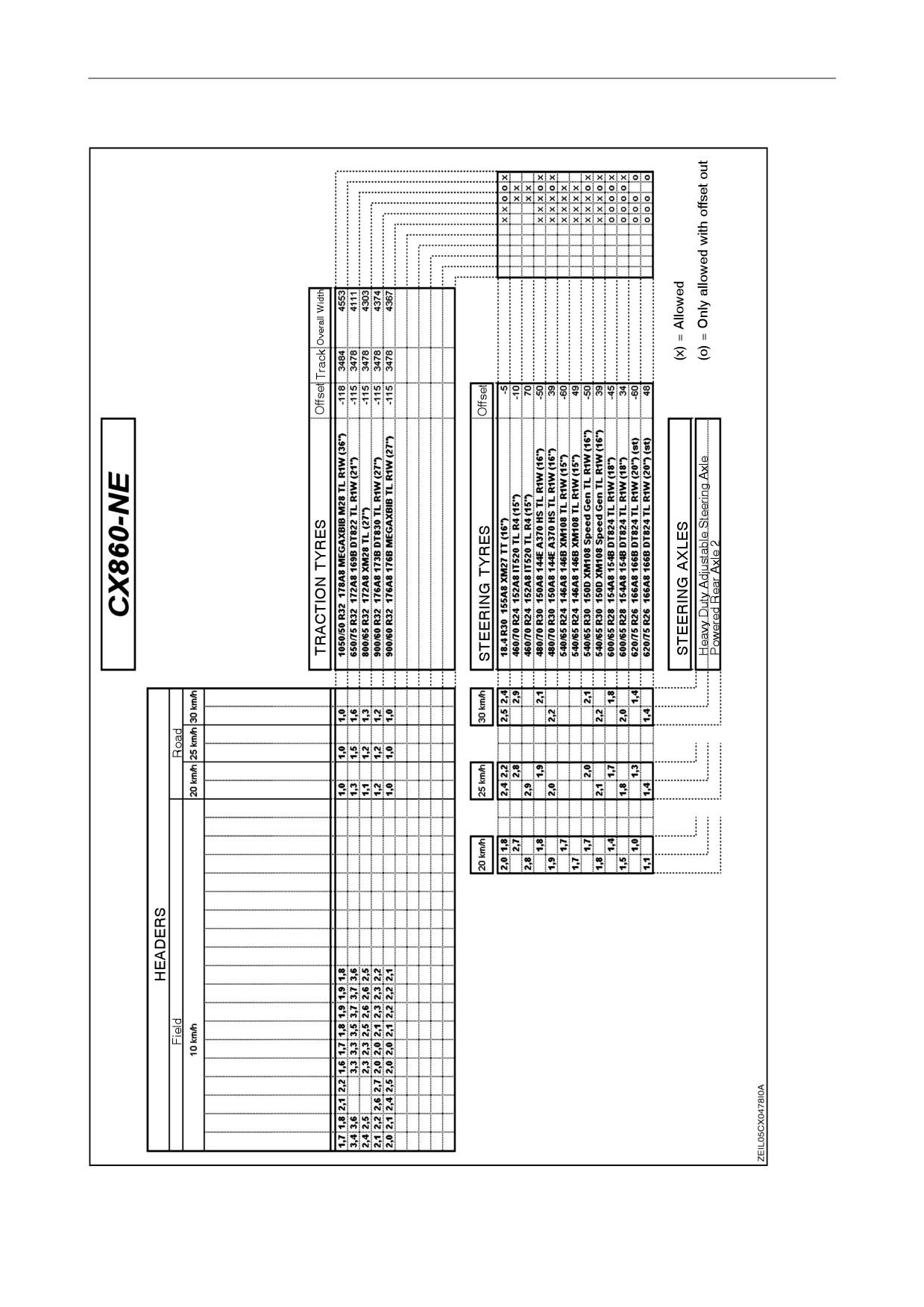
SECTION 8 - SPECIFICATIONS
r edae Noh
r edae Noh
r edae Noh
)
C27 tf
(
0 r edae i Granh3
)
C
47 tf (
0 r edae x Fleh3
)
C
(
89 r edae e i a
h
z
m
3
8 / 6 3
R8
)
C
(
89 r edae e i a
h
z
m0 3
R8
)
C
(
89 r edae e i a
h
z
m
3
8 / 6 3
R6
)
C
(
89 r edae e i a
h
z
m0 3
R6
)
C49 tf 9 r ep r i Granda3(
)
C49 tf 6 r ep r i Granda3(
)
C49 tf 0 r ep r i Granda3(
)
C29 tf
(
5 r ep r e Ricda2
8-28
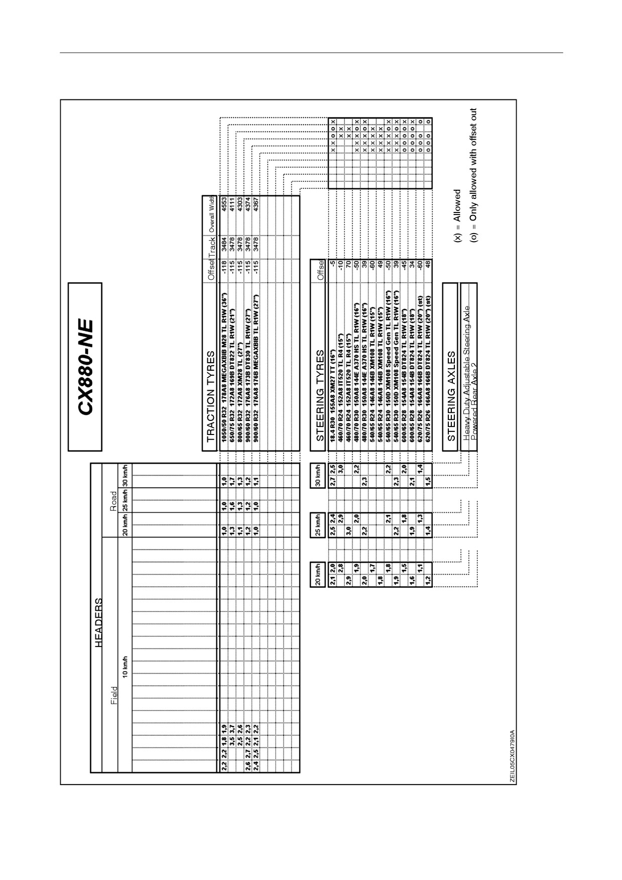
SECTION 8 - SPECIFICATIONS
r edae Noh
r edae Noh
r edae Noh
)
C
(
89 r edae e i a
h
z
m8 / 6
3
3
R8
)
C
(
89 r edae e i a
h
z
m0 3
R8
)
C49 tf 9 r ep r i Granda3(
)
C49 tf 6 r ep r i Granda3(
8-29
SECTION 8 - SPECIFICATIONS
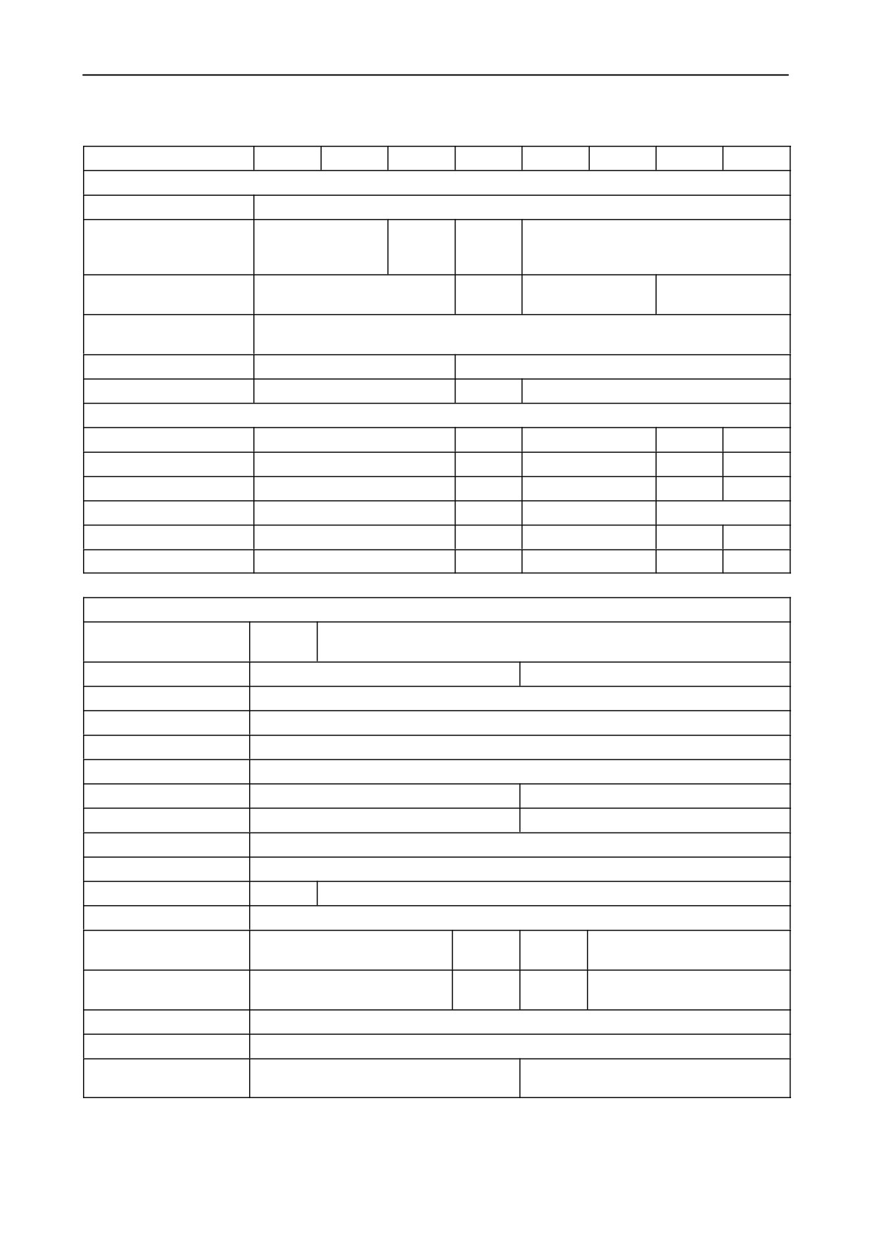
TECHNICAL DATA
CX720
CX740
CX760
CX780
CX820
CX840
CX860
CX880
HEADER (Europe)
Grain header
- High-Capacity
13 - 15 - 17 - 20 ft
13 - 15 -
15 - 17 -
17 - 20 - 24 - 30 ft
17 - 20 -
20 - 24 ft
24 ft
- Extra-Capacity
-
20 - 24 ft
-
20 - 24 - 30 ft
- Varifeedt
Cutting height
- 350 mm / + 1550 mm (-13-3/4”/ + 61-3/128”)
(tyres 800/65 R32)
(with lateral flotation and front face adjustment)
Flex header
19 ft
19 ft - 25 ft
Maize header
5 row (rigid) / 6 row (rigid+flip-up)
All types
6 - 8 row (rigid + flip-up)
HEADER (Australia)
Grain header (72C)
-
25 - 30 ft
-
30 ft
-
Flex header (74C)
-
25 - 30 ft
-
30 ft
-
Maize header (98C)
-
6 - 8 row
-
6 - 8 row
8 row
Windrow pick-up (76C)
-
14 ft
-
14 ft
Grain draper (94C)
-
25 - 30 ft
-
30-36-39ft
36 - 39 ft
Rice draper (92C)
-
21 - 25 ft
-
25 ft
STRAW ELEVATOR
Type
Lateral
Lateral flotation or Lateral flotation with front face adjustment
flotation
Straw elevator width
1314 mm (51-3/4”)
1574 mm (61-31/32”)
Cradle width
1885 mm (74 -1/4”)
Header hooks width
2084 mm (82-3/64”)
Top shaft speed (*)
357 rpm
Lower shaft speed (*)
546 rpm
Number of chains
3
4
Number of slats
30
45
Type of slats
S-slats
Protection
Spring-loaded slip clutch set at 600 Nm (443 ft.lbs)
Drive line (belt)
2 x 2 HB
2 x 2 HB (Grain) / 1 x 4 HB (Maize)
Lateral flotation
3° deg 20’
Header lift cylinders
63 mm
70 mm
63 mm
70 mm
(diameter)
(2-1/2”)
(2-3/4”)
(2-1/2”)
(2-3/4”)
Optional header lift
75 mm
75 mm
cylinders (diameter)
(2-15/16”)
(2-15/16”)
Reverser system
Hydraulic
Stone trap
Pivotable
Intermediate plate covers
2
3
(If equipped)
(*) high idle (no load)
8-30
SECTION 8 - SPECIFICATIONS
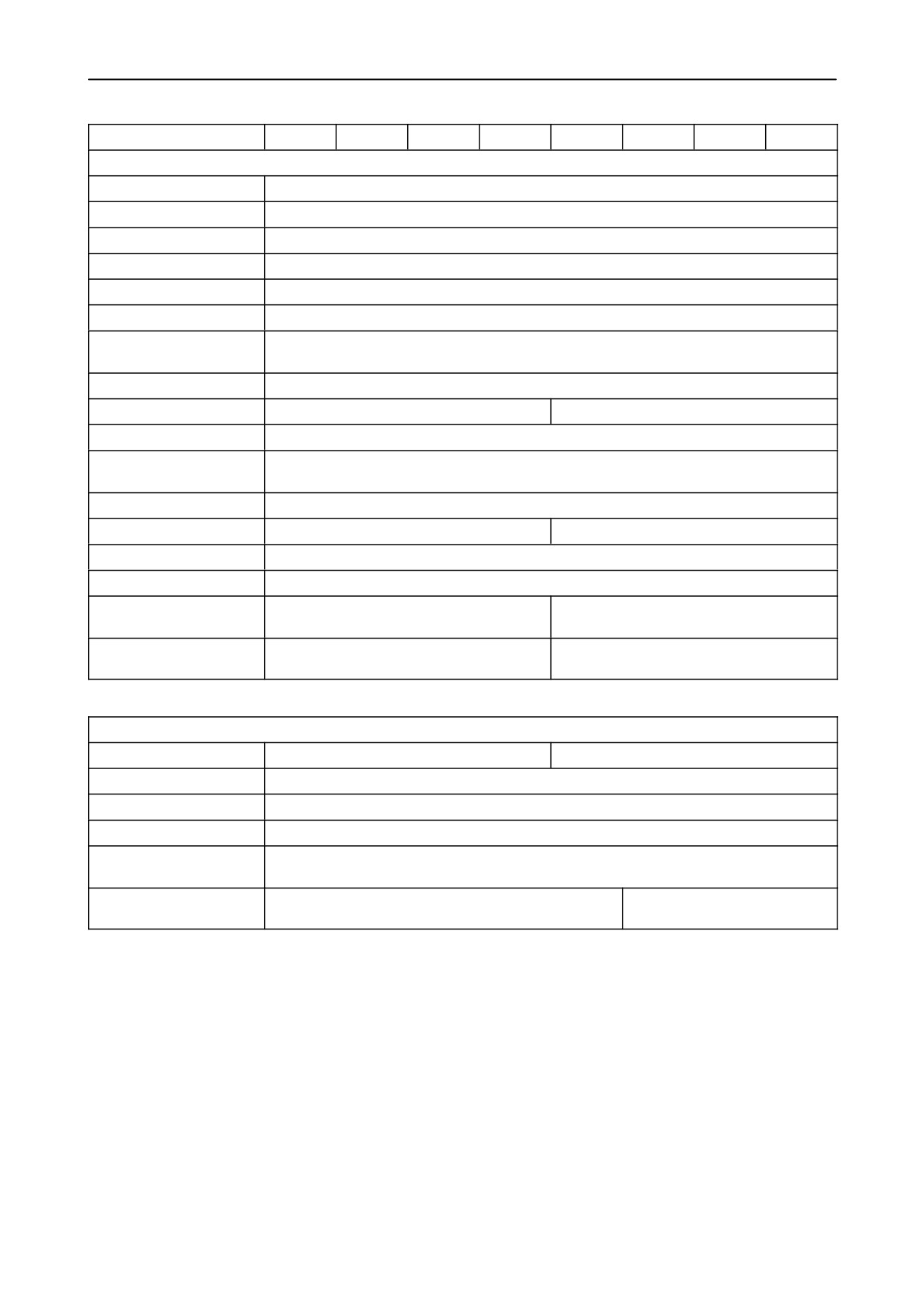
CX720
CX740
CX760
CX780
CX820
CX840
CX860
CX880
THRESHING DRUM
Drum speed (*)
305 rpm to 905 rpm
Speed control
Electrical
Speed read-out
InfoViewt
Drum drive
3 HB
Variator drive
71 x 30 mm (2-51/64” x 1-3/16”)
Drum type
Standard / Universal with bars / Universal with teeth
Standard / Universal
drum with bars
Drum diameter
750 mm (29-17/32”)
Drum width
1300 mm (51-3/16”)
1560 mm (61-1/2”)
Number of bars
5 x 2 = 10
Universal drum with
Access
teeth
Drum diameter
750 mm (29-17/32”)
Drum width
1300 mm (51-3/16”)
1560 mm (61-1/2”)
Number of bars
5 x 2 = 10
Tooth spacing
56 or 84 mm (2-13/64” or 3-5/16”)
Number of teeth: 56 mm
5 x 22 + 5 x 23
10 x 27
(2-13/64”)
Number of teeth: 84 mm
10 x 15
10 x 18
(3-5/16”)
DRUM CONCAVE
Concave width
1320 mm (51-31/32”)
1580 mm (62-13/64”)
Setting
Electrical
Read out
InfoViewt
Fine adjustment
At suspension points
Concave options
Small Grain (SG) / Corn / Rice
(Europe)
Concave options
-
Heavy Duty Moderate / Heavy
(Not for Europe)
Duty Universal / Grass seed
(*) high idle (no load)
8-31
SECTION 8 - SPECIFICATIONS
CX720
CX740
CX760
CX780
CX820
CX840
CX860
CX880
Small grain concave
Wrap angle
111°
Concave area
0.98 m2
1.18 m2
(1519
sq.
in)
(1829
sq.
in)
Number of bars
16
Distance between wires
14 mm (9/16”)
Wire diameter
3.5 mm (9/64”)
De-awning plates
2 (fitted to concave) - adjustment from the inside
Heavy Duty Moderate
Not for Europe
Wrap angle
-
111°
Concave area
-
1.18 m2
(1829
sq.
in)
Number of bars
-
16
Distance between wires
-
14 mm (9/16”)
Wire diameter
-
3.5 mm (9/64”)
Maize concave
Wrap angle
111°
Concave area
0.98 m2
1.18 m2
(1519
sq.
in)
(1829
sq.
in)
Number of bars
12
Distance between wires
26 mm (1-3/128”)
Wire diameter
6 mm (1/4”)
Heavy Duty Universal
Not for Europe
Wrap angle
-
111°
Concave area
-
1.18 m2
(1829
sq.
in)
Number of bars
-
16
Distance between wires
-
14 mm (9/16”)
Wire diameter
-
3.5 mm (9/64”)
Rice concave
Wrap angle
111°
Concave area
0.98 m2
1.18 m2
(1519
sq.
in)
(1829
sq.in)
Number of bars
4
Number of teeth (56mm)
68
81
(2-13/64”)
Number of teeth (84mm)
45
54
( 3-5/16”)
8-32
SECTION 8 - SPECIFICATIONS
CX720
CX740
CX760
CX780
CX820
CX840
CX860
CX880
Grass seed concave
Not for Europe
Wrap angle
-
111°
Concave area
-
1.18 m2
(1829
sq.in)
Number of teeth (56mm)
-
106
(2-13/64”)
BEATER
Drive
1 HC
Speed (*)
Same as drumspeed
Width
1300 mm (51-3/16”)
1560 mm (61-1/2”)
Diameter
475 mm (18-45/64”)
Blades
8
Pins
8 (Optional)
BEATER CONCAVE
Wrap angle
26°
Number of bars
5
Width
1320 mm (51-31/32”)
1580 mm (62-13/64”)
Concave area
0.24 m2
0.29 m2
(372
sq.
in)
(449
sq.
in)
Distance between wires
32 mm (1-1/4”)
Wire diameter
6 mm (1/4”)
Setting
Mechanical (2 settings: up and down)
ROTARY SEPARATOR
Drive
2 HB
Speed (*)
387 or 700 rpm
Width
1300 mm (51-3/16”)
1560 mm (61-1/2”)
Diameter
720 mm (28-11/32”)
Number of teeth
12 x 7
6 x 8 + 6 x 9
(*) high idle (no load)
8-33
SECTION 8 - SPECIFICATIONS
CX720
CX740
CX760
CX780
CX820
CX840
CX860
CX880
ROTARY SEPARATOR CONCAVE
Wrap angle
95.5°
Number of bars
14
Width
1320 mm (51-31/32”)
1580 mm (62-13/64”)
Concave area
0.78 m2
0.93 m2
(1209
sq.
in)
(1442
sq.
in)
Distance between wires
32 mm (1-1/4”)
Wire diameter
6 mm (1/4”)
Setting
Mechanical (2 settings: up and down)
STRAW FLOW BEATER
Drive
4 HB
Speed (*)
1144 rpm
Width
1300 mm (51-3/16”)
1560 mm (61-1/2”)
Diameter
315 mm (12-13/32”)
Number of plates
4
STRAW WALKERS
Drive
1 HB
Speed (*)
215 rpm
Width
1320 mm (51-31/32”)
1580 mm (62-13/64”)
Number
5
6
Number of steps
5
Length
3670 mm (144-1/2”)
Separation area
4.94 m2
5.93 m2
(7657
sq.
in)
(9192
sq.
in)
(*) high idle (no load)
8-34
SECTION 8 - SPECIFICATIONS
CX720
CX740
CX760
CX780
CX820
CX840
CX860
CX880
CLEANING SHOE
Grain pan
Removable or fixed
Frame width
1320 mm (51-31/32”)
1580 mm (62-13/64”)
Cleaning shoe
Self Levelling (SL) or Fixed Shoe (FS)
Drive
1 HC
Speed (*)
513 rpm or 580 rpm
Upper shaker shoe
Horizontal stroke
45 mm (1-3/4”)
Throwing angle
- Front
27°
- Rear
27°
Grain pan width
1320 mm (51-31/32”)
1580 mm (62-13/64”)
Grain pan length
1730 mm (68-1/8”)
Grain pan + rake surface
2.284 m2
2.733 m2
(3540
sq.i
in)
(4236
sq.
in)
Pre-sieve width
1320 mm (51-31/32”)
1580 mm (62-13/64”)
Pre-sieve length
901 mm (35-15/32”)
Pre-sieve area (with rake)
1.190 m2
1.424 m2
(1845
sq.
in)
(2207
sq.
in)
Upper sieve width
1320 mm (51-31/32”)
2 x 790 mm (2 x 31-13/128”)
Upper sieve length
1445 mm (56-7/8”)
Upper sieve area
1.908 m2
2.284 m2
(2957
sq.
in)
(3540
sq.
in)
Upper sieve positions
2
Upper sieve grate surface
0.198 m2
0.237 m2
(307
sq.
in)
(367
sq.
in)
Upper sieve graepel
0.211 m2
0.253 m2
surface
(327
sq.
in)
(392
sq.
in)
Lower shaker shoe
Horizontal stroke
40 mm (1-1/2”)
Throwing angle
15°
Lower sieve length
1445 mm (56-7/8”)
Lower sieve width
1320 mm (51-31/32”)
2 x 790 mm (2 x 31-13/128”)
Lower sieve area
1.908 m2
2.284 m2
(2957
sq.
in)
(3540
sq.
in)
Lower sieve position
1
Total sieve area under
5.4 m2
6.5 m2
(8370
sq.
in)
(10075
sq.in)
wind control
(*) high idle (no load)
8-35
SECTION 8 - SPECIFICATIONS
CX720
CX740
CX760
CX780
CX820
CX840
CX860
CX880
CLEANING FAN
Drive
Variator belt over eccentric shaft
Speed (standard) variator
475 rpm to 900 rpm
(*)
Fan speed reducer (*)
210 rpm to 495 rpm
Speed control
Electric
Read out
InfoViewt
Number of blades
6
RETURN SYSTEM
Return type
Cross auger + roto-thresher
Returns
Single
Double
Cross auger and
760 rpm
roto-thresher (*)
Returns auger speed (*)
570 rpm
GRAIN TANK, UNLOAD
Grain tank capacity with
covers
-Grain tank width: 3 m
7600 litres
9000 litres
-
213 US bu
252 US bu
-Grain tank width: 3.3 m
-
9000 litres
10500 litres
252 US bu
294 US bu
Grain tank capacity with
extensions
-Grain tank width: 3.3 m
-
10220 l
11620 litres
286 US bu
325.4 US bu
Unloading concept
Over the top unloading
Unloading rate
105 litres/s - 3 Bu/s
Unloading tube length
5.5 m (18 ft)
Unloading tube extension
0.9 m (3 ft)
kit
(*) high idle (no load)
8-36
SECTION 8 - SPECIFICATIONS
CX720
CX740
CX760
CX780
CX820
CX840
CX860
CX880
ENGINE
Type
NH675
NH675
NH675
NH675
NH675
NH675
IVECO
IVECO
TA/AG
TA/AH
TA/AJ
TA/AB
TA/AJ
TA/AB
F2B
F3A
Gross power
170 kW
185 kW
207 kW
220 kW
207 kW
220 kW
245 kW
275 kW
(ISO TR14396)
(231 CV)
(252 CV)
(281 CV)
(299 CV)
(281 CV)
(299 CV)
(333 CV)
(374 CV)
Governor
Electronically
Boost
No
20 kW
(27 hp)
Rated speed
2100 rpm
Low idle speed
1300 rpm
High idle speed
2100 rpm
Cylinder displacement
7500 cc
7800 cc
10300 cc
Bore
112 mm
115 mm
125 mm
(4-13/32”)
(4-17/32”)
(4-59/64”)
Stroke
127 mm
125 mm
140 mm
(5”)
(4-59/64”)
(5-1/2”)
Waterpump speed
3859 rpm
3444 rpm
3906 rpm
Ventilator speed
1531 rpm
Crankcase capacity
23 litres
24 litres
29 litres
(with filters)
(6.08 US gal)
6.3 US gal
7.7 US gal
Battery
2 x 12V - 92 Ah
Alternator type
190 Ampère (12 Volt)
Alternator speed
5830 rpm
6090 rpm
6531 rpm
Starter motor
4.2 kW (12 Volt)
4.5 kW (24 Volt)
Air compressor speed
2677 rpm
2373 rpm
2856 rpm
Fuel tank
500 Litres
750 Litres
(130 US gal)
(200 US gal)
Rotary screen speed
282 rpm
Air conditioning
3616 rpm
3150 rpm
3444 rpm
compressor
STRAW CHOPPER & SPREADER
Speed (*)
1200 or 3200 rpm
Chaff blower drive
Hydro
(*) high idle (no load)
8-37
SECTION 8 - SPECIFICATIONS
CX720
CX740
CX760
CX780
CX820
CX840
CX860
CX880
HYDRAULIC SYSTEM
Reservoir capacity
50 litres (13 US gal)
Pump capacity
0 - 114 l/m
Maximum pressure
210 bar (3046 PSI)
Steering valve
Maximum pressure
185 bar (2683 PSI)
Shock valve setting
235 - 255 bar (not for NA) (3409 - 3699 PSI)
HYDROSTATIC SYSTEM
Pump capacity
100 cc
110 cc
130 cc
Motor capacity
100 cc
130 cc
CAB
Operator seat
Standard or air-suspensed seat
Instructional seat
No
Deluxe
No
Deluxe
Storage box
No
Standard
No
Optional
Air conditioning
Manual
Manual /
Manual
Manual / Automatic
Automatic
Heating
Standard (integrated in air conditioning system)
Powered heated mirrors
Standard
Wipers
Big wiper system
TRACTION
Traction gearbox
Medium I
Medium II
High
Transmission
4 speed hydrostatic
Oil capacity
19 litres (5 US gal)
Differential Eur./NA
18/71
16/71
20/61
Ground speed (forward)
(On tyres 800/65 R32-172 A8-DT822)
1st gear (full load)
6.3 km/h (3.9 MPH)
2nd gear (full load)
11.4 km/h (7.1 MPH)
3rd gear (full load)
14.8 km/h (9.2 MPH)
4th gear (full load)
Maximum permissible ground speed
Steering axle
HD fixed / HD adjustable (H.D.A.S.A.) / Powered (P.R.A.)
8-38
SECTION 8 - SPECIFICATIONS
CX720
CX740
CX760
CX780
CX820
CX840
CX860
CX880
FINAL DRIVES
Type
Standard
Heavy Duty
Planetary
Mud seal
No
Optional
No
Optional
Ratio
11/111
1/13.09
Oil capacity
7.2 litres
7.85 litres
6.7 litres
1.9 US gal
2.07 US gal
1.77 US gal
WEIGHT
With grain tank covers (-)
Self levelling clean. shoe
-Fixed steering axle
14300 kg
14600 kg
15300 kg
15400 kg
15800 kg
31525 lbs
32187 lbs
33730 lbs
33950 lbs
34832 lbs
-HDASA
14400 kg
14500 kg
14800 kg
15500 kg
15900 kg
31746 lbs
31966 lbs
32628 lbs
34171 lbs
35053 lbs
-PRA
14700 kg
15000 kg
15700 kg
15800 kg
16200 kg
32407 lbs
33069 lbs
34612 lbs
34832 lbs
35714 lbs
Fixed cleaning shoe
-Fixed steering axle
14200 kg
14500 kg
15200 kg
15300 kg
15700 kg
31305 lbs
31966 lbs
33510 lbs
33730 lbs
34612 lbs
-HDASA
14300 kg
14600 kg
15300 kg
15400 kg
15800 kg
31525 lbs
32187 lbs
33730 lbs
33950 lbs
34832 lbs
-PRA
14600 kg
14900 kg
15600 kg
15700 kg
16100 kg
32187 lbs
32848 lbs
34391 lbs
34612 lbs
35494 lbs
With grain tank extensions (-)
Self levelling clean. shoe
- Fixed steering axle
-
15300 kg
15700 kg
33730 lbs
34612 lbs
- H.D.A.S.A.
-
15400 kg
15500 kg
15800 kg
33950 lbs
34171 lbs
34832 lbs
- P.R.A.
-
15700 kg
16100 kg
34612 lbs
35494 lbs
Fixed cleaning shoe
- Fixed steering axle
-
15100 kg
15200 kg
15500 kg
33289 lbs
33510 lbs
34171 lbs
- H.D.A.S.A.
-
15300 kg
15700 kg
33730 lbs
34612 lbs
- P.R.A.
-
15500 kg
15600 kg
15900 kg
34171 lbs
34391 lbs
35053 lbs
(-): configuration
- Without header
- Empty grain tank
- Without straw chopper
- Traction tyres 800/65R32-172A8-DT822
- Steering tyres 540/65R24-146A8-XM108
- Full fuel tank
8-39
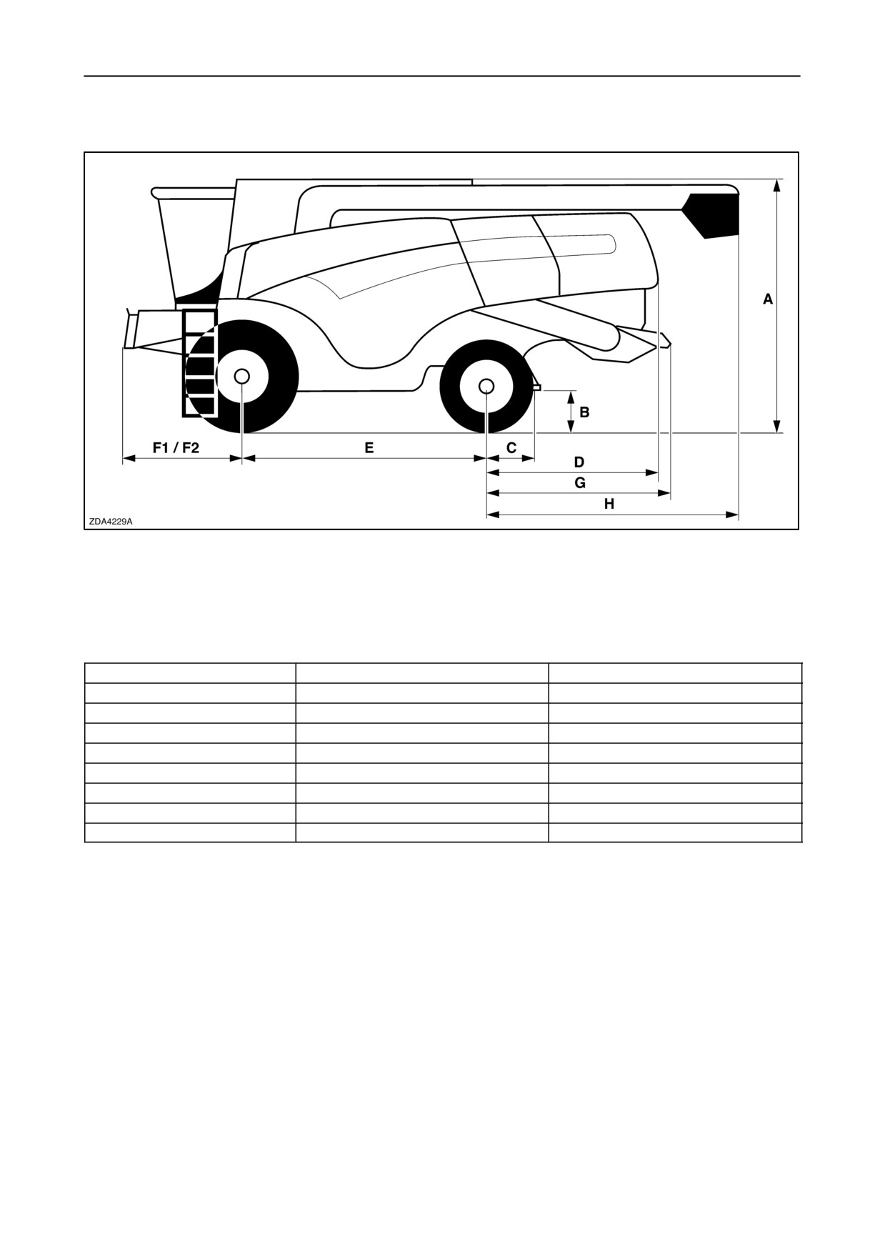
SECTION 8 - SPECIFICATIONS
DIMENSIONS
TRACTION TYRES
A
B
620/75 R34-170A8-DT820
3.93 m (154-3/4”)
0.58 m (23”)
650/75 R32-172A8-DT822
3.92 m (154-21/64”)
0.57 m (22-1/2”)
710/75 R34-178A8-MegaXBib
3.96 m (155-28/64”)
0.61 m (24-1/64”)
800/65 R32-172A8-DT822
3.92 m (154-21/64”)
0.57 m (22-1/2”)
800/65 R32-172A8-XM28
3.92 m (154-21/64”)
0.57 m (22-1/2”)
900/60 R32-176A8-DT830
3.96 m (155-28/64”)
0.61 m (24-1/64”)
1050/50 R32-178A8-MegaXbi
3.98 m (156-11/16”)
0.62 m (24-1/4”)
Tracks
4.07 m (160-1/4”)
0.72 m (28-11/32”)
F1 = Straw elevator with lateral flotation and front face adjustment
F2 = Straw elevator with lateral flotation
B-C = Fixed trailer hitch
H = Unloading tube 5.5 m (18 ft) with extension 0.9 m (3 ft)
8-40
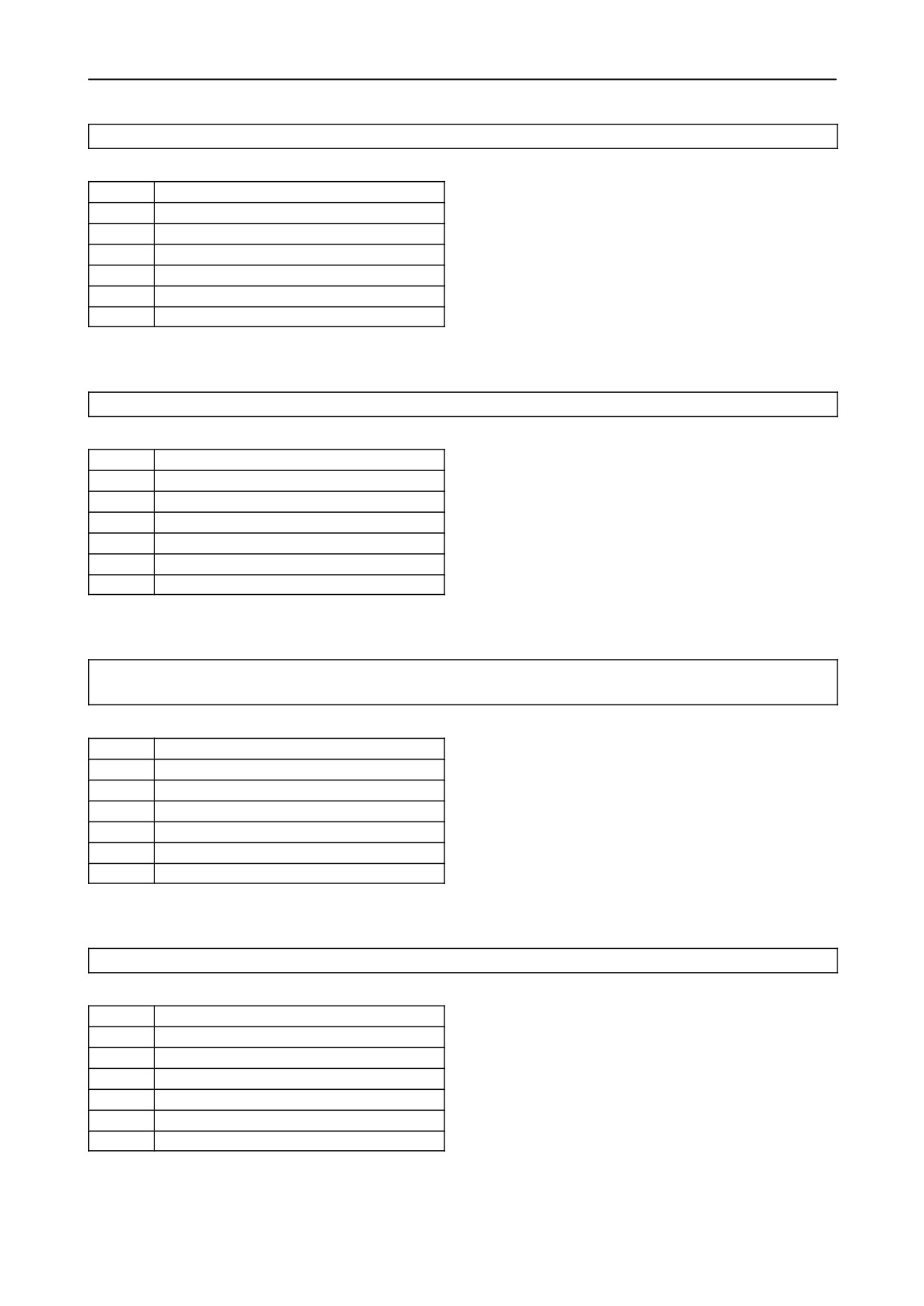
SECTION 8 - SPECIFICATIONS
Powered Rear Axle in the front position
C
0.88 m (34-5/8”)
D
2.70 m (106-19/64”)
E
3.64 m (143-5/16”)
F1
2.55 m (100-3/8”)
F2
2.51 m (98-3/16”)
G
2.86 m (112-19/32”)
H
3.78 m (148-13/16”)
Powered Rear Axle in the rear position
C
0.85 m (33-1/2”)
D
2.66 m (104-3/4”)
E
3.67 m (144-1/2”)
F1
2.55 m (100-3/8”)
F2
2.51 m (98-13/16”)
G
2.82 m (111-3/128”)
H
3.74 m (147-1/4”)
Fixed Steering axle
Heavy Duty Adjustable Steering Axle in the front position
C
0.79 m (31-13/128”)
D
2.6m (102-3/8”)
E
3.73 m (146-109/128”)
F1
2.55 m (100-3/8”)
F2
2.51 m (98-13/16”)
G
2.77 m (109-1/16”)
H
3.69 m (145-1/4”)
Heavy Duty Adjustable Steering Axle in the rear position
C
0.76 m (29-59/64”)
D
2.57m (101-3/16”)
E
3.76 m (148-1/32”)
F1
2.55 m (100-3/8”)
F2
2.51 m (98-13/16”)
G
2.73 m (107-1/2”)
H
3.65 m (143-45/64”)
8-41
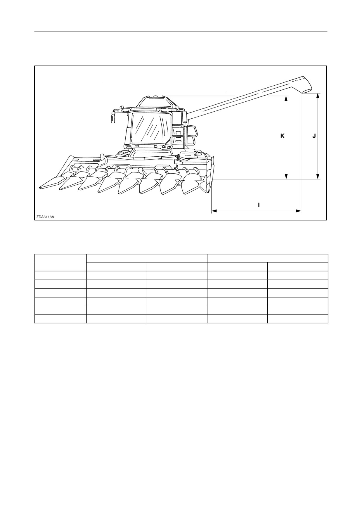
SECTION 8 - SPECIFICATIONS
DIMENSION I (3)
3 m (9.8 ft) grain tank
3.3 m (10.8 ft) grain tank
Header
5.5 m (18 ft)
6.4 m (21 ft)
5.5 m (18 ft)
6.4 m (21 ft)
13 ft
4.01 m (13.1 ft)
4.88 m (16 ft)
4.16 m (13.6 ft)
5.03 m (16.5 ft)
15 ft
3.70 m (12.1 ft)
4.57 m (15 ft)
3.85 m (12.6 ft)
4.72 m (15.5 ft)
17 ft
3.40 m (11.1 ft)
4.27 m (14 ft)
3.55 m (11.6 ft)
4.42 m (14.5 ft)
20 ft
2.94 m (9.6 ft)
3.81 m (12.5 ft)
3.09 m (10.1 ft)
3.96 m (13 ft)
24 ft
2.30 m (7.6 ft)
3.20 m (10.5 ft)
2.48 m (8.1 ft)
3.35 m (11 ft)
30 ft
1.42 m (4.6 ft)
2.28 m (7.5 ft)
1.57 m (5.1 ft)
2.43 m (8 ft)
(3)
Unloading tube maximum open
8-42
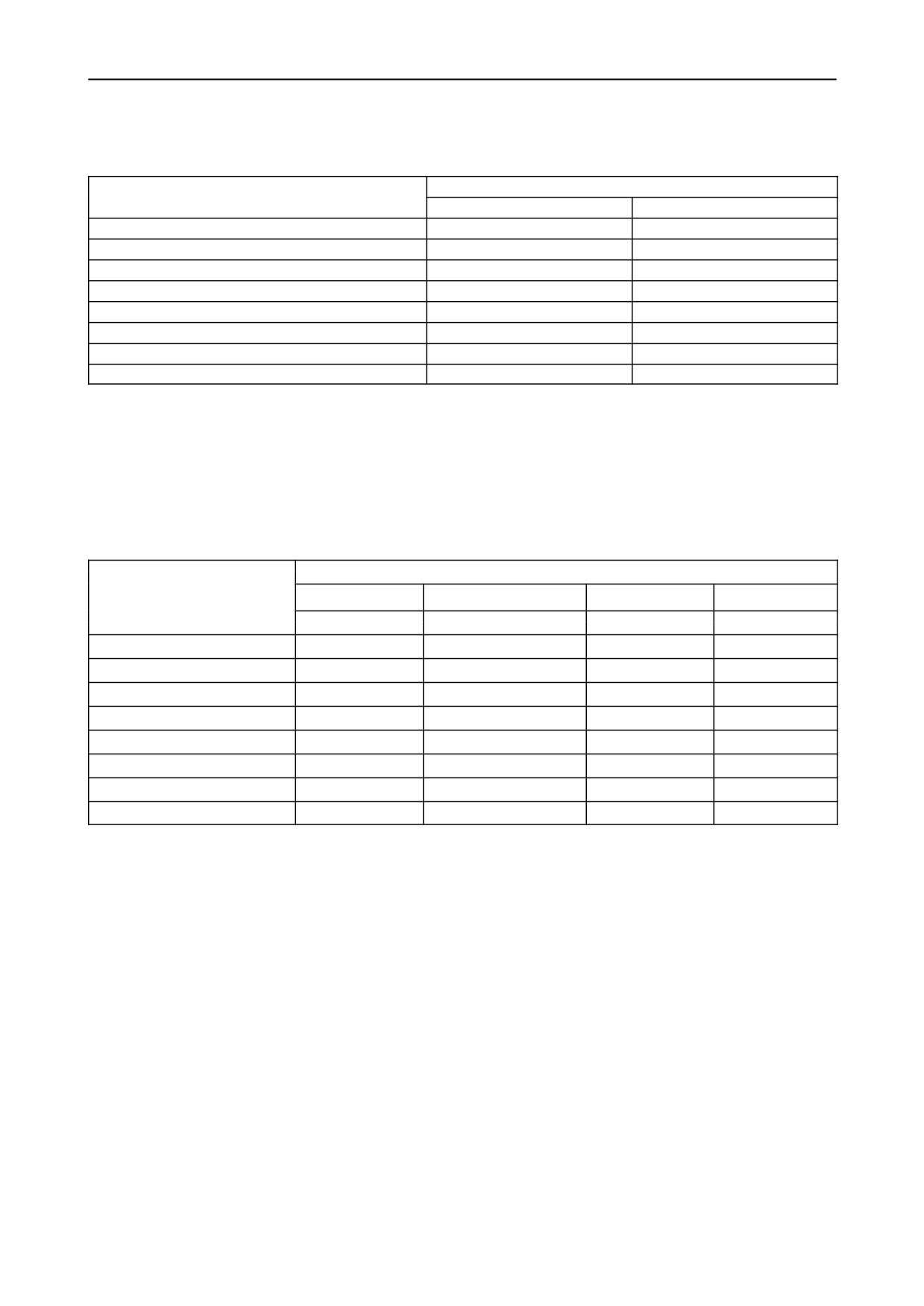
SECTION 8 - SPECIFICATIONS
DIMENSION J (3)
Unloading tube length
TRACTION TYRES
5.5 m (18 ft)
6.4 m (21 ft)
620/75 R34-170A8-DT820
4.37 m (14.3 ft)
4.63 m (15.2 ft)
650/75 R32-172A8-DT822
4.37 m (14.3 ft)
4.62 m (15.2 ft)
710/75 R34-178A8-MegaXBib
4.40 m (14.4 ft)
4.66 m (15.3 ft)
800/65 R32-172A8-DT822
4.36 m (14.3 ft)
4.62 m (15.2 ft)
800/65 R32-172A8-XM28
4.36 m (14.3 ft)
4.62 m (15.2 ft)
900/60 R32-176A8-DT830
4.40 m (14.4 ft)
4.66 m (15.3 ft)
1050/50 R32-178A8-MegaXbi
4.42 m (14.5 ft)
4.68 m (15.3 ft)
Tracks
4.52 m (14.8 ft)
4.78 m (15.7 ft)
(3)
Unloading tube maximum open
DIMENSION K (4)
Grain tank width
3m
3m
3.3m
3.3m
TRACTION TYRES
CX720/740
CX760/780/820/840/860
CX820/840
CX860/880
620/75 R34-170A8-DT820
4.38 m (14.4 ft)
4.64 m (15.2 ft)
4.40 m (14.4 ft)
4.71 m (15.5 ft)
650/75 R32-172A8-DT822
4.37 m (14.3 ft)
4.63 m (15.2 ft)
4.40 m (14.4 ft)
4.70 m (15.4 ft)
710/75 R34-178A8-MegaXBib
4.41 m (14.5 ft)
4.67 m (15.3 ft)
4.45 m (14.6 ft)
4.74 m (15.6 ft)
800/65 R32-172A8-DT822
4.37 m (14.3 ft)
4.63 m (15.2 ft)
4.40 m (14.4 ft)
4.70 m (15.4 ft)
800/65 R32-172A8-XM28
4.37 m (14.3 ft)
4.63 m (15.2 ft)
4.40 m (14.4 ft)
4.70 m (15.4 ft)
900/60 R32-176A8-DT830
4.41 m (14.5 ft)
4.67 m (15.3 ft)
4.45 m (14.6 ft)
4.74 m (15.6 ft)
1050/50 R32-178A8-MegaXbi
4.43 m (14.5 ft)
4.68 m (15.4 ft)
4.45 m (14.6 ft)
4.75 m (15.6 ft)
Tracks
4.52 m (14.8 ft)
4.78 m (14.8 ft)
4.55 m (14.9 ft)
4.85 m (15.9 ft)
(4)
Grain tank covers completely open
8-43
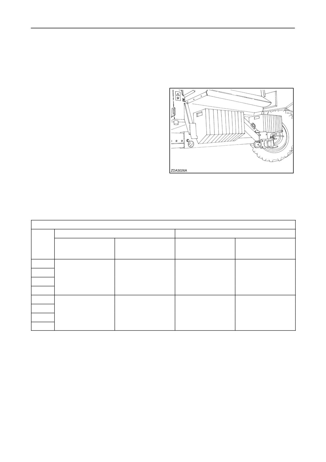
SECTION 8 - SPECIFICATIONS
COUNTERWEIGHTS
For some attachments, counterweights are a legal
requirement to ensure a safe road transport.
Available counterweights (as accessory)
• Frame counterweights (to be attached to the rear
frame): 35 kg/element (77.2 lbs)
1
• Steering wheel counterweights
(to be installed on the steering wheel rim):
20 kg/element (44.1 lbs)
Ballast requirements if a straw chopper is installed
H.D.A.S.A.
Powered Rear Axle
20 ft flip-up grain
8 row flip-up (*)
20 ft flip-up grain
8 row flip-up (*)
header or
header or
6 row flip-up (*)
6 row flip-up (*)
CX880
CX860
No counterweights
16 x 35 kg (560 kg)
No counterweights
10 x 35 kg (350 kg)
CX840
needed
needed
CX820
CX780
CX760
10 x 35 kg (350 kg)
18 x 35 kg+20 x 20 kg
4 x 35 kg (140 kg)
18 x 35 kg+10 x 20 kg
CX740
(1030 kg)
(830 kg)
CX720
(*) : Maize header with stalk chopper
Remark: If other mounted header attachments than
mentioned in the table: Add weights and make always
sure that there is a weight of at least 4700 kg on the
steering axle.
8-44
SECTION 8 - SPECIFICATIONS
Liquid ballast, based on water/calcium chloride
solution up to -15° C . (Not valid for Germany, Italy
nor Scandinavian countries)
CAUTION
Do not use liquid weight (ballast) in wheels as this is
not recommended and forbidden practice in some
countries.
A minimum liquid filling of at least 366 kg is needed,
then other additional ballast weights are not needed
for the following combinations:
• CX720-CX740-CX760-CX780 equipped with
P.R.A. or H.D.A.S.A., straw chopper and with a
6-row flip-up maize header.
• CX820-CX840-CX860-CX880 equipped with
P.R.A., straw chopper and with a 8-row flip-up
maize header.
8-45
SECTION 8 - SPECIFICATIONS
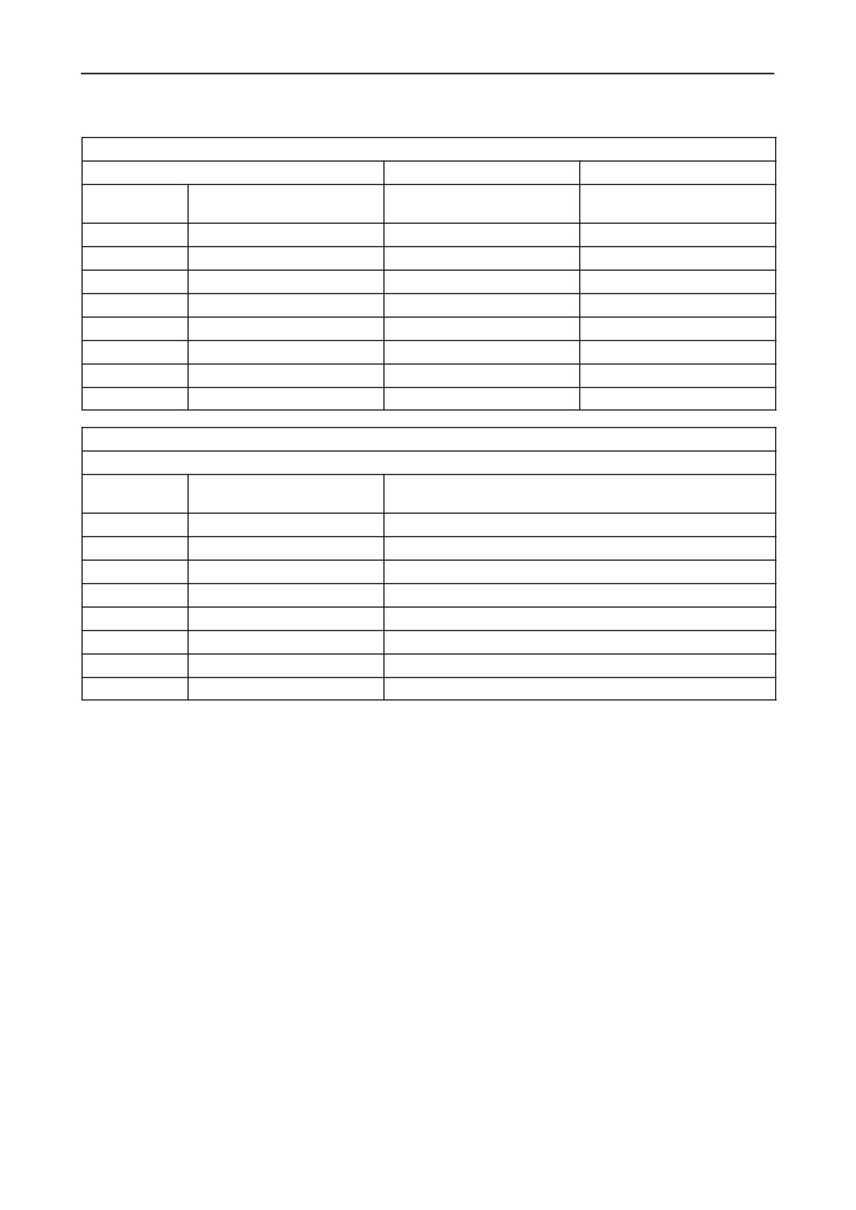
For other combinations, refer to tables below.
CX720-CX740-CX760-CX780 with straw chopper and 8-row flip-up maize header
H.D.A.S.A.
Powered Rear Axle
Steering tyres
Liquid ballast weight per set
Additional weights required
Additional weights required
tyres
(in addition to liquid ballast)
(in addition to liquid ballast)
14.9 x 24
366 kg
8 x 35 kg+20 x 20 kg
8 x 35 kg+6 x 20 kg
460/70 R24
462 kg
4 x 35 kg+20 x 20 kg
4 x 35 kg+20 x 20 kg
540/65 R24
616 kg
2 x 35 kg+20 x 20 kg
2 x 35 kg+20 x 20 kg
480/70 R30
636 kg
2 x 35 kg+20 x 20 kg
2 x 35 kg+20 x 20 kg
540/65 R30
712 kg
20 x 20 kg
8 x 20 kg
600/65 R28
828 kg
16 x 20 kg
4 x 20 kg
18.4 R30
710 kg
20 x 20 kg
8 x 20 kg
620/75 R26
1010 kg
6 x 20 kg
No counter weights needed
CX820-CX840-CX860-CX880 with straw chopper and 8-row flip-up maize header
H.D.A.S.A.
Steering tyres
Liquid ballast weight per set
Additional weights required (in addition to liquid ballast)
tyres
14.9 x 24
366 kg
6 x 35 kg (210 kg)
460/70 R24
462 kg
6 x 35 kg (210 kg)
540/65 R24
616 kg
No counter weights needed
480/70 R30
636 kg
No counter weights needed
540/65 R30
712 kg
No counter weights needed
600/65 R28
828 kg
No counter weights needed
18.4 R30
710 kg
No counter weights needed
620/75 R26
1010 kg
No counter weights needed
Remark: If other mounted header attachments than
mentioned in the tables: Add weights and make
always sure that there is a weight of at least 4700 kg
on the steering axle.
8-46
SECTION 9 - 1ST 50 HOUR SERVICE SHEETS
SECTION 9 - 1ST 50 HOUR SERVICE SHEETS
CHECK AND ADJUST, AS REQUIRED (CUSTOMER COPY)
1. Perform the 50 hour grease zerk service . .. j
12. Check hydraulic/hydrostatic oil level .
j
2. Check wheel nut and torques
j
13. Check all chain and belt tensions
j
3. Check steering ball joints
j
14. Lubricate all chains
j
4. Check and clean air conditioning condensor j
15. Check coolant level (shunt tank)
j
5. Check and clean air conditioning evaporator j
16. Check brake fluid level
j
6. Check air conditioning filter-drier
j
17. Clean cab air filter
j
7. Check tire pressure
j
18. Check fuel level
j
8. Check drum concave setting
j
19. Clean stone trap
j
9. Check electrolyte level in batteries .
j
20. Drain water from fuel system prefilter/
10. Check engine oil level
j
water separator
j
11. Check engine gearbox oil level
j
21. Check the tension of the grain elevator chain j
THE INSPECTION HAS BEEN MADE
COMBINE MODEL NO:
COMBINE SERIAL NO:
SIGNATURE OWNER, DATE:
SIGNATURE DEALER, DATE:
9-1
SECTION 9 - 1ST 50 HOUR SERVICE SHEETS
CHECK AND ADJUST, AS REQUIRED (DEALER COPY)
1. Perform the 50 hour grease zerk service . .. j
12. Check hydraulic/hydrostatic oil level .
j
2. Check wheel nut and torques
j
13. Check all chain and belt tensions
j
3. Check steering ball joints
j
14. Lubricate all chains
j
4. Check and clean air conditioning condensor j
15. Check coolant level (shunt tank)
j
5. Check and clean air conditioning evaporator j
16. Check brake fluid level
j
6. Check air conditioning filter-drier
j
17. Clean cab air filter
j
7. Check tire pressure
j
18. Check fuel level
j
8. Check drum concave setting
j
19. Clean stone trap
j
9. Check electrolyte level in batteries .
j
20. Drain water from fuel system prefilter/
10. Check engine oil level
j
water separator
j
11. Check engine gearbox oil level
j
21. Check the tension of the grain elevator chain j
THE INSPECTION HAS BEEN MADE
COMBINE MODEL NO:
COMBINE SERIAL NO:
SIGNATURE OWNER, DATE:
SIGNATURE DEALER, DATE:
9-3
CNH BELGIUM N.V., Leon Claeystraat 3A, B-8210 ZEDELGEM - Belgium
AFTER SALES - Technical Information
Print No. 604.63.341.00 - 7th Edition - 07 - 2005
PRINTED IN BELGIUM
COPYRIGHT BY CNH BELGIUM N.V.
All rights reserved. No part of the text or illustrations of
this publication may be reproduced.
New Holland policy is one of continuous improvement and the right to change prices, specification or equipment
at any time without notices is reserved.
All data given in this publication is subject to production variations. Dimensions and weight are approximate only
and the illustrations do not necessarily show products in standard condition. For exact information about any
particular product, please consult your New Holland Dealer.

LUBRICANTS TO BE USED
A new line of specially formulated Ambra-NH lubricants, based on own engineering specifications, is available
from your NEW HOLLAND dealer. For this combine we recommend:
ITEM
Servicing
Amount
NEW HOLLAND
NEW
Lubricant
International
interval
unit
brand name
HOLLAND
grade
specification
specification
Grease zerks
10 h - 50 h
AMBRA GR9
NH710A
NLGI 2
M1C 137-A
100 h - 200 h
or
or
AMBRA GR75MD
NH720A
M1C 75-B
Engine (sump
Check daily
with filter)
Change
23 litres
(CNH engine)
- after first 100h
(6.08 US gal)
- every 300h or
annually
AMBRA
NH330H
SAE 15W40
API CH-4
(Iveco engine)
Check daily
CX860
or
-CX860
Change
24 litres
MASTER GOLD
ACEA E3/E5
-CX880
- after first 100h
(6.34 US gal)
HSP
- every 600h or
CX880
annually
29 litres
(7.7 US gal)
Hydraulic and
Check daily
70 litres
AMBRA
NH646H
HV 46
DIN 51524
Change
HYDROSYSTEM
Hydrostatic
(18.5 US gal)
PART 2 HV46
46 HV
system
- after first 100h
ISO VG-46
(oil+filters)
(filters only)
or
or
or
AMBRA
NH410B
M2C 134-D
- every 600h or
MULTI G
annually
(oil+filters)
Engine
Check daily
11 litres
AMBRA
NH646H
HV 46
DIN 51524
Change
(2.9 US gal)
HYDROSYSTEM
gearbox
PART 2 HV46
- after first 100h
46 HV
ISO VG -46
(filter only)
or
or
or
- every 600h or
AMBRA
annually
NH410B
MULTI G
M2C 134-D
(oil+filter)

ITEM
Servicing
Amount
NEW HOLLAND
NEW
Lubricant
International
interval
unit
brand name
HOLLAND
grade
specification
specification
Traction
Change
19 litres
AMBRA
NH520A
SAE 80W90
API GL-5
- after first 100h
(5 US gal)
HYPOIDE 90
gearbox
MIL-L-2105D
- every 600h or
annually
Final drives:
Change
Standard
- after first 100h
7.2 litres
AMBRA
NH520A
SAE 80W90
API GL-5
(1.9 US gal)
HYPOIDE 90
MIL-L-2105D
Heavy duty
- every 600h or
7.85 litres
(2.07 US gal)
Planetary
annually
6.7 litres
(1.77 US gal)
Unloading
Change
- after first 100h
drive gearbox
AMBRA
NH520A
SAE 80W90
API GL-5
0.6 litres
HYPOIDE 90
MIL-L-2105D
– every 600h or
(0.16 US gal)
annually
Unloading
Check only
- after first 100h
tube gearbox
0.3 litres
AMBRA
NH520A
SAE 80W90
API GL-5
– every 600h or
(0.08 US gal)
HYPOIDE 90
MIL-L-2105D
annually
Bubble-up
Change
- after first 100h
gearbox
0.25 litres
AMBRA
NH520A
SAE 80W90
API GL-5
– every 600h or
(0.07 US gal)
HYPOIDE 90
MIL-L-2105D
annually
Chains
100h
AMBRA
NH520A
SAE 80W90
API GL-5
200h
HYPOIDE 90
MIL-L-2105D
Threaded rods
200h
Pivot points
Brake system
Check daily
0.825 litres
AMBRA
NH800A
SAE J 1703
ISO 4925
Change every
(0.21 US gal)
SYNTFLUID 4
or
two years
NHTSA
116-DOT4
Cooling system
Check daily
CNH engine
50% AGRIFLU
NH900A
-
-
40 litres
50% water
- CNH engine
(10.6 US gal)
Change
- Iveco engine
CX860
- every
two
46 litres
years
(12.2 US gal)
CX880
50 litres
(13.2 US gal)
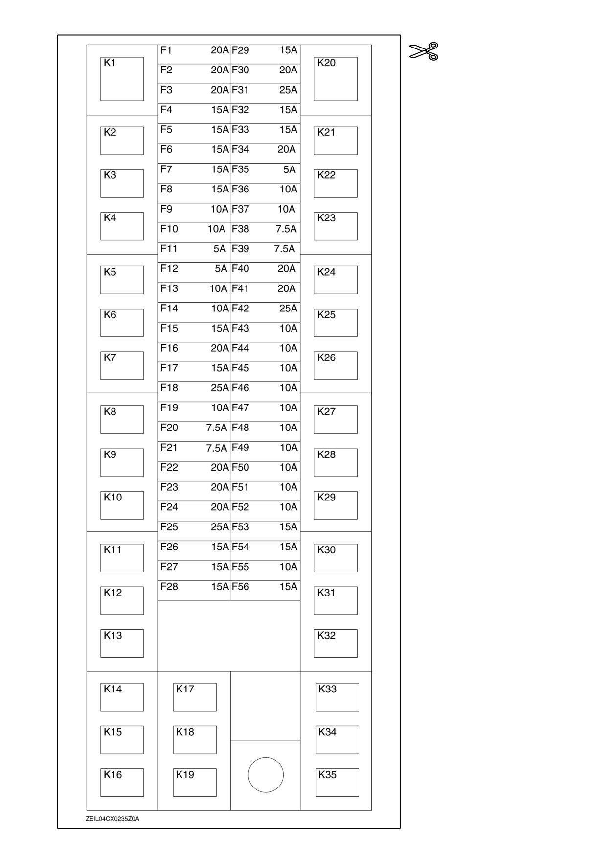
Please cut out this picture and
place it in the pocket adhered
to the inner side of the fuse
and relay panel cover.
Ref. to
Print No.
604.63.341.00
7th Edition
English
07/05
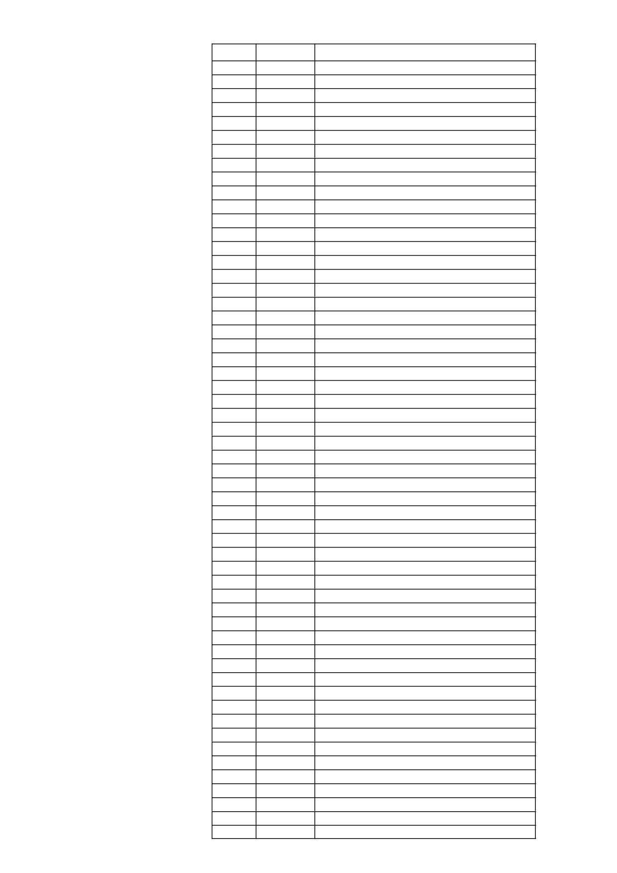
Fuse n_
Amperage
Function
F1
20A
ECU power
F2
20A
Accessory 2
F3
20A
Accessory 1
F4
15A
Wiper
F5
15A
Cigar lighter
F6
15A
Left-hand cab operating lights
F7
15A
Right-hand cab operating lights
F8
15A
Accessory outlet
F9
10A
Washer/Mirror
F10
10A
Accessory socket
F11
5A
Radio
F12
5A
Global Positioning System
F13
10A
Tranceiver
F14
10A
Service lights
F15
15A
Service sockets
F16
20A
Seat pump
F17
15A
Separator blower
F18
25A
Main blower
F19
10A
A/C clutch
F20
7.5A
Left-hand marker lights
F21
7.5A
Right-hand marker lights
F22
20A
Shoe levelling actuator
F23
20A
Throttle/brush/reel variator
F24
20A
Reverser/Fan
F25
25A
Transmission gearshift motor
F26
15A
HGS turntable (SmartSteert)
F27
15A
Sieves/Chopper
F28
15A
Fuel pump
F29
15A
Distance operating lights
F30
20A
Header operating lights
F31
25A
Cab roof operating lights
F32
15A
High beam
F33
15A
Low beam
F34
20A
Under shield lights
F35
5A
Radio
F36
10A
Combine Control Module 2A
F37
10A
Combine Control Module 2B
F38
7.5A
Key switch
F39
7.5A
Memory/ka power
F40
20A
Combine Control Module 1
F41
20A
Combine Control Module 2
F42
25A
Combine Control Module 3/Cab
F43
10A
Combine Control Module 1A
F44
10A
Combine Control Module 1B
F45
10A
Header Height Control power
F46
10A
Hydraulic reel drive
F47
10A
CCM 3 (precision farming/SmartSteert)
F48
10A
Right-hand module
F49
10A
Cab/ HGS sensor (SmartSteert)
F50
10A
Side/Tube lights
F51
10A
Horn/Marker lights
F52
10A
Dome/Brake lights
F53
15A
Revolving flash light(s)
F54
15A
Lower operating lights
F55
10A
Rear operating lights
F56
15A
Hazard lights
REPAIR MANUAL
CX720 , CX740 , CX760 , CX780 , CX820 , CX840 , CX860 , CX880
Contents
INTRODUCTION
DISTRIBUTION SYSTEMS
A
PRIMARY HYDRAULIC POWER SYSTEM
A.10.A
SECONDARY HYDRAULIC POWER SYSTEM
A.12.A
HYDRAULIC COMMAND SYSTEM
A.14.A
PNEUMATIC SYSTEM
A.20.A
ELECTRICAL POWER SYSTEM
A.30.A
LIGHTING SYSTEM
A.40.A
ELECTRONIC SYSTEM
A.50.A
POWER PRODUCTION
B
ENGINE
B.10.A
FUEL AND INJECTION SYSTEM
B.20.A
AIR INTAKE SYSTEM
B.30.A
EXHAUST SYSTEM
B.40.A
ENGINE COOLANT SYSTEM
B.50.A
LUBRICATION SYSTEM
B.60.A
STARTING SYSTEM
B.80.A
POWER TRAIN
C
POWER COUPLING Fixed coupling
C.10.B
TRANSMISSION Mechanical
C.20.B
TRANSMISSION Hydrostatic
C.20.F
PROCESS DRIVE Primary process drive
C.50.B
TRAVELLING
D
FRONT AXLE
D.10.A
REAR AXLE
D.12.A
2WD-4WD SYSTEM Hydrostatic
D.14.E
STEERING Hydraulic
D.20.C
SERVICE BRAKE Hydraulic
D.30.C
2
4/7/2006
PARKING BRAKE Hydraulic
D.32.C
BODY AND STRUCTURE
E
SHIELD
E.20.A
OPERATOR AND SERVICE PLATFORM
E.30.A
USER CONTROLS AND SEAT
E.32.A
USER CONTROLS AND SEAT Operator seat
E.32.C
USER PLATFORM
E.34.A
ENVIRONMENT CONTROL Heating system
E.40.B
ENVIRONMENT CONTROL Air-conditioning system
E.40.C
ENVIRONMENT CONTROL Heating, ventilation and air-conditioning
E.40.D
SAFETY SECURITY ACCESSORIES Safety
E.50.B
TOOL POSITIONING
G
LIFTING
G.10.A
LEVELLING
G.30.A
CROP PROCESSING
K
FEEDING Reel feeding
K.25.B
FEEDING Header feeding
K.25.D
FEEDING Feeder housing
K.25.E
THRESHING Conventional threshing
K.40.B
SEPARATING Beating
K.42.B
SEPARATING Rotary separator
K.42.C
SEPARATING Straw walker
K.42.E
SEPARATING Straw flow beater
K.42.F
STORING AND HANDLING Grain storing
K.60.B
CLEANING Primary cleaning
K.62.B
CLEANING Tailings return system
K.62.C
RESIDUE HANDLING Straw chopper
K.64.C
RESIDUE HANDLING Spreader
K.64.D
RESIDUE HANDLING Chaff blower
K.64.F
2
4/7/2006
Contents
INTRODUCTION
Foreword ( - A.10.A.40)
3
Basic instructions ( - A.90.A.05)
4
Torque ( - A.90.A.10)
7
Conversion factors ( - A.92.A.21)
10
Product identification ( - A.80.A.10)
11
604_34_001_06 2 4/7/2006
2
INTRODUCTION
Foreword ( - A.10.A.40)
IMPORTANT INFORMATION
All repair and maintenance works listed in this manual must be carried out only by staff belonging to the NEW HOL-
LAND Service network, strictly complying with the instructions given and using, whenever required, the special tools.
Anyone who carries out the above operations without complying with the prescriptions shall be responsible for the
subsequent damages.
The manufacturer and all the organizations of its distribution chain, including - without limitation - national, regional or
local dealers, reject any responsibility for damages due to the anomalous behavior of parts and/or components not
approved by the manufacturer himself, including those used for the servicing or repair of the product manufactured
or marketed by the Manufacturer. In any case, no warranty is given or attributed on the product manufactured or
marketed by the Manufacturer in case of damages due to an anomalous behavior of parts and/or components not
approved by the Manufacturer.
No reproduction, though partial of text and illustrations allowed
604_34_001_06 2 4/7/2006
3
INTRODUCTION
Basic instructions ( - A.90.A.05)
SHIMMING
For each adjustment operation, select adjusting shims and measure individually using a micrometer, then add up
the recorded values. Do not rely on measuring the entire shimming set, which may be incorrect, or the rated value
indicated on each shim.
ROTATING SHAFT SEALS
For correct rotating shaft seal installation, proceed as follows:
•
before assembly, allow the seal to soak in the oil it will be sealing for at least thirty minutes
•
thoroughly clean the shaft and check that the working surface on the shaft is not damaged
•
position the sealing lip facing the fluid; with hydrodynamic lips, take into consideration the shaft rotation direction
and position the grooves so that they will deviate the fluid towards the inner side of the seal
•
coat the sealing lip with a thin layer of lubricant (use oil rather than grease) and fill the gap between the sealing
lip and the dust lip on double lip seals with grease
•
insert the seal in its seat and press down using a flat punch, do not tap the seal with a hammer or mallet
•
whilst inserting the seal, check that it is perpendicular to the seat; once settled, make sure that it makes contact
with the thrust element, if required
•
to prevent damaging the seal lip on the shaft, position a protective guard during installation operations
O-RING SEALS
Lubricate the O-RING seals before inserting them in the seats, this will prevent them from overturning and twisting,
which would jeopardise sealing efficiency.
SEALING COMPOUNDS
Apply one of the following sealing compounds on the mating surfaces marked with an X: RTV SILMATE,
RHODORSIL CAF 1 or LOCTITE PLASTIC GASKET. Before applying the sealing compound, prepare the surfaces
as follows:
•
remove any incrustations using a metal brush;
•
thoroughly de-grease the surfaces using one of the following cleaning agents: trichlorethylene, petrol or a water
and soda solution.
COTTER PINS
When fitting split cotter pins, ensure that the pin notch is positioned in the direction of the force required to stress the
pin. Spiral cotter pins do not require special positioning.
604_34_001_06 2 4/7/2006
4
INTRODUCTION
PROTECTING THE ELECTRONIC/ ELECTRICAL SYSTEMS DURING CHARGING OR WELD-
ING
To avoid damage to the electronic/electrical systems, always observe the following:
1.
Never make or break any of the charging circuit connections, including the battery connections, when the engine
is running.
2.
Never short any of the charging components to ground.
3.
Always disconnect the ground cable from the battery before arc welding on the combine or on any header at-
tached to the combine.
•
Position the welder ground clamp as close to the welding area as possible.
•
If welding in close proximity to a computer module, then the module should be removed from the combine.
•
Never allow welding cables to lay on, near or across any electrical wiring or electronic component while
welding is in progress.
4.
Always disconnect the negative cable from the battery when charging the battery in the combine with a battery
charger.
IMPORTANT: If welding must be performed on the unit, either the combine or the header (if it is attached), the battery
ground cable must be disconnected from the combine battery. The electronic monitoring system and charging system
will be damaged if this is not done.
Remove the battery ground cable. Reconnect the cable when welding is completed.
WARNING
Battery acid causes severe burns. Batteries contain sulfuric acid. Avoid contact with skin, eyes or clothing.
Antidote - EXTERNAL: flush with water. INTERNAL: drink large quantities of water or milk. Follow with milk
of magnesia, beaten egg or vegetables oil. Call physician immediately. EYES: flush with water for 15 minutes
and get prompt medical attention. 84-110
604_34_001_06 2 4/7/2006
5

INTRODUCTION
SPARE PARTS
Only use original NEW HOLLAND spare parts bearing the logo shown below.
geninfo_03
1
Only genuine spare parts guarantee the same quality, duration and safety as original parts, as they are the same
parts that are assembled during standard production. Only NEW HOLLAND genuine spare parts can offer this
guarantee. When ordering spare parts, always provide the following information:
•
Machine model (commercial name) and serial number
•
part number of the ordered part, which can be found in the "Microfiches" or the "Spare Parts Catalogue", used
for order processing
TOOLS
The tools that NEW HOLLAND suggests and illustrate in this manual have been:
•
specifically researched and designed for use with NEW HOLLAND machines
•
essential for reliable repair operations
•
accurately built and rigorously tested so as to offer efficient and long-lasting operation
By using these tools, Repair Personnel will benefit from:
•
operating in optimal technical conditions
•
obtaining the best results
•
saving time and effort
•
working in safe conditions
NOTE: Wear limit values indicated for certain parts should be considered to be recommended, but not binding. The
terms "front", "rear", "right-hand" and "left-hand" (when referred to different parts) are determined from the rear, facing
in the direction of travel of the machine during operation.
604_34_001_06 2 4/7/2006
6
INTRODUCTION
Torque ( - A.90.A.10)
Minimum hardware tightening torques Nm lb ft lb in for normal assembly applications un-
less otherwise stated
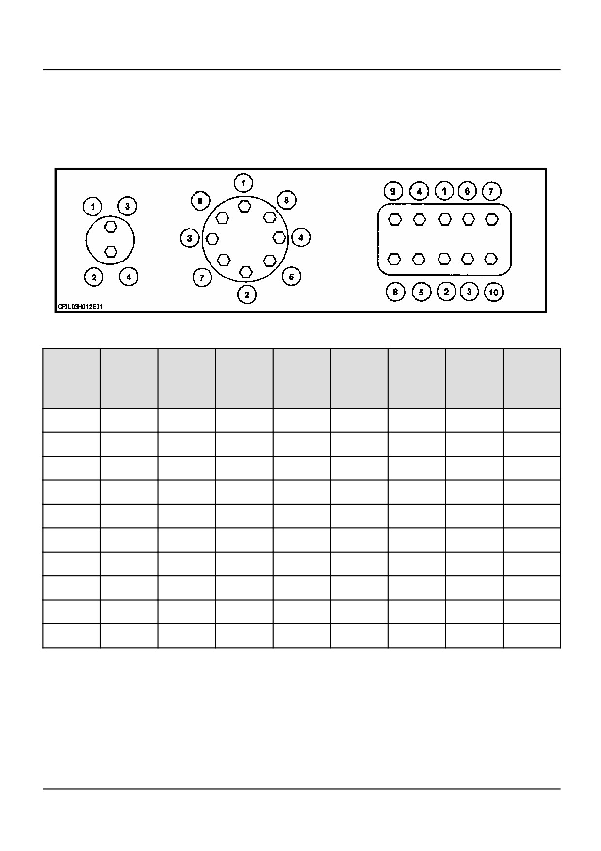
IMPORTANT: Shown below is the suggested initial torque tightening sequences for general applications, tighten in
sequence from item 1 through to the last item of the hardware.
df5019-1
1
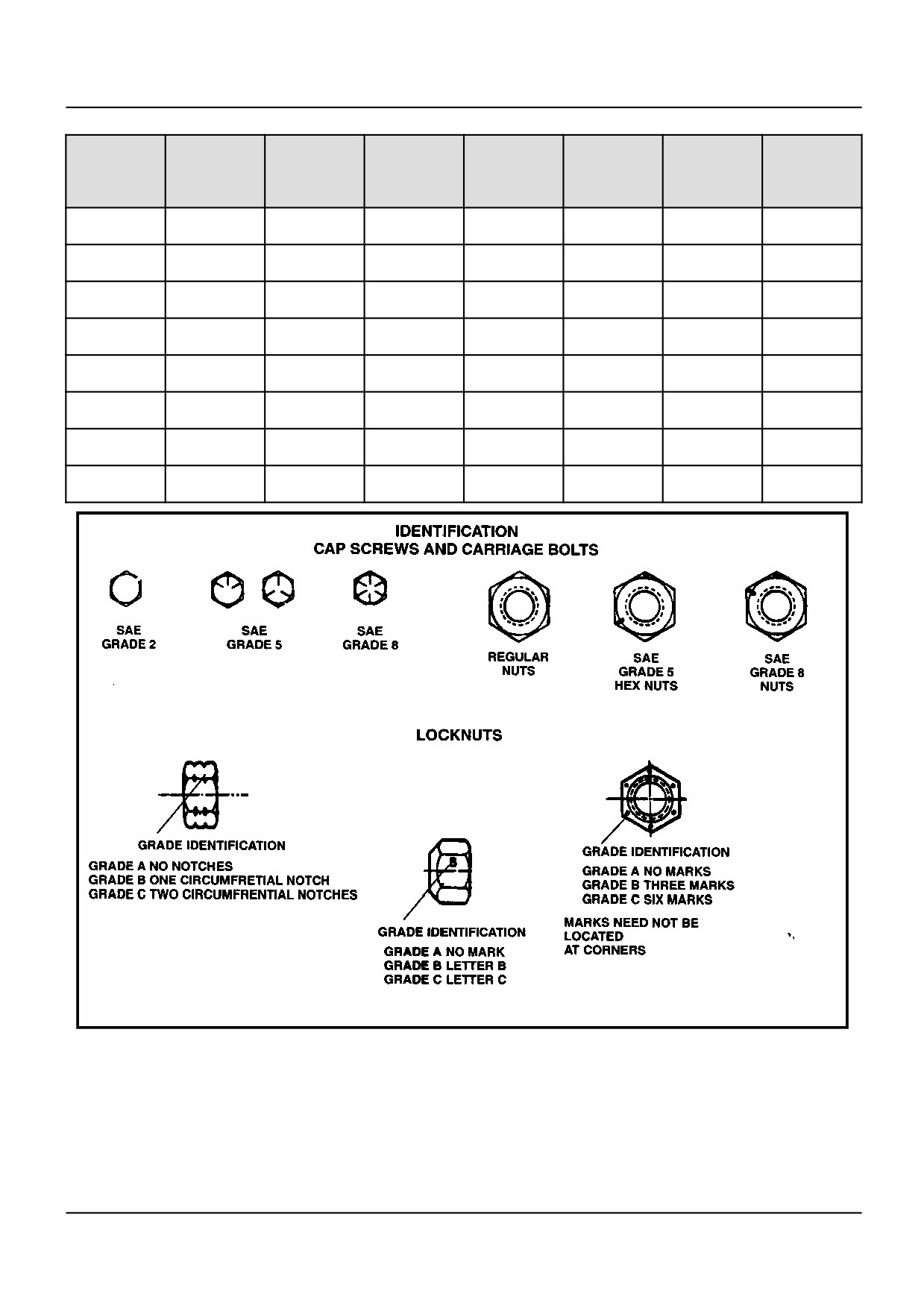
Imperial hardware
Nominal
SAE
SAE
SAE
SAE
SAE
SAE
LOCK-
LOCK-
Size
GRADE 2
GRADE
GRADE 5
GRADE
GRADE
GRADE
NUTS
NUTS
Unplated
2 plated
Unplated
5 plated
8Unplated
8 plated
GR.B
GR.B
or Silver
w/ZnCr
or Silver
w/ZnCr
or Silver
w/ZnCr
w/GR5
w/GR8
plated
GOLD
plated
GOLD
plated
GOLD
BOLT
BOLT
1/4
6.2 Nm
8.1 Nm
9.7 Nm
13 Nm
14 Nm
18 Nm
6.9 Nm
9.8 Nm
55 lb in
72 lb in
86 lb in
112 lb in
121 lb in
157 lb in
61 lb in
86 lb in
5/16
13 Nm
17 Nm
20 Nm
26 Nm
28 Nm
37 Nm
14 Nm
20 Nm
115 lb in
149 lb in
178 lb in
229 lb in
250 lb in
324 lb in
125 lb in
176 lb in
3/8
23 Nm
30 Nm
35 Nm
46 Nm
50 Nm
65 Nm
26 Nm
35 Nm
17 lb ft
22 lb ft
26 lb ft
34 lb ft
37 lb ft
48 lb ft
19 lb ft
26 lb ft
7/16
37 Nm
47 Nm
57 Nm
73 Nm
80 Nm
104 Nm
41 Nm
57 Nm
27 lb ft
35 lb ft
42 lb ft
54 lb ft
59 lb ft
77 lb ft
30 lb ft
42 lb ft
1/2
27 Nm
73 Nm
87 Nm
113 Nm
123 Nm
159 Nm
61 Nm
88 Nm
42 lb ft
54 lb ft
64 lb ft
83 lb ft
91 lb ft
117 lb ft
45 lb ft
64 lb ft
9/16
81 Nm
104 Nm
125 Nm
163 Nm
176 Nm
229 Nm
88 Nm
125 Nm
60 lb ft
77 lb ft
92 lb ft
120 lb ft
130 lb ft
169 lb ft
65 lb ft
92 lb ft
5/8
112 Nm
145 Nm
174 Nm
224 Nm
244 Nm
316 Nm
122 Nm
172 Nm
83 lb ft
107 lb ft
128 lb ft
165 lb ft
180 lb ft
233 lb ft
90 lb ft
127 lb ft
3/4
198 Nm
256 Nm
306 Nm
397 Nm
432 Nm
560 Nm
217 Nm
305 Nm
146 lb ft
189 lb ft
226 lb ft
293 lb ft
319 lb ft
413 lb ft
160 lb ft
226 lb ft
7/8
193 Nm
248 Nm
495 Nm
641 Nm
698 Nm
904 Nm
350 Nm
494 Nm
142 lb ft
183 lb ft
365 lb ft
473 lb ft
515 lb ft
667 lb ft
258 lb ft
364 lb ft
1.0
289 Nm
373 Nm
742 Nm
960 Nm
1048 Nm
1356 Nm
523 Nm
739 Nm
213 lb ft
275 lb ft
547 lb ft
708 lb ft
773 lb ft
1000 lb ft
386 lb ft
545 lb ft
604_34_001_06 2 4/7/2006
7
INTRODUCTION
Metric hardware
Nominal
CLASS 5.8
CLASS 5.8
CLASS 8.8
CLASS 8.8
CLASS 10.9
CLASS 10.9
LOCKNUT
Size
UNPLATED
UNPLATED
UNPLATED
UNPLATED
UNPLATED
UNPLATED
CL.8
w/CL8.8
BOLT
M4
1.7 Nm
2.2 Nm
2.6 Nm
3.4 Nm
3.7 Nm
4.8 Nm
1.8 Nm
15 lb in
19 lb in
23 lb in
30 lb in
33 lb in
42 lb in
16 lb in
M6
5.8 Nm
7.6 Nm
8.9 Nm
12 Nm
13 Nm
17 Nm
6.3 Nm
51 lb in
67 lb in
79 lb in
102 lb in
115 lb in
150 lb in
56 lb in
M8
14 Nm
18 Nm
22 Nm
28 Nm
31 Nm
40 Nm
15 Nm
124 lb in
159 lb in
195 lb in
248 lb in
274 lb in
354 lb in
133 lb in
M10
28 Nm
36 Nm
43 Nm
56 Nm
61 Nm
79 Nm
30 Nm
21 lb ft
27 lb ft
32 lb ft
41 lb ft
45 lb ft
58 lb ft
22 lb ft
M12
49 Nm
63 Nm
75 Nm
97 Nm
107 Nm
138 Nm
53 Nm
36 lb ft
46 lb ft
55 lb ft
72 lb ft
79 lb ft
102 lb ft
39 lb ft
M16
121 Nm
158 Nm
186 Nm
240 Nm
266 Nm
344 Nm
131 Nm
89 lb ft
117 lb ft
137 lb ft
177 lb ft
196 lb ft
254 lb ft
97 lb ft
M20
237 Nm
307 Nm
375 Nm
485 Nm
519 Nm
671 Nm
265 Nm
175 lb ft
107 lb ft
277 lb ft
358 lb ft
383 lb ft
495 lb ft
195 lb ft
M24
411 Nm
531 Nm
648 Nm
839 Nm
897 Nm
1160 Nm
458 Nm
303 lb ft
392 lb ft
478 lb ft
619 lb ft
662 lb ft
855 lb ft
338 lb ft
5057
2
604_34_001_06 2 4/7/2006
8
INTRODUCTION
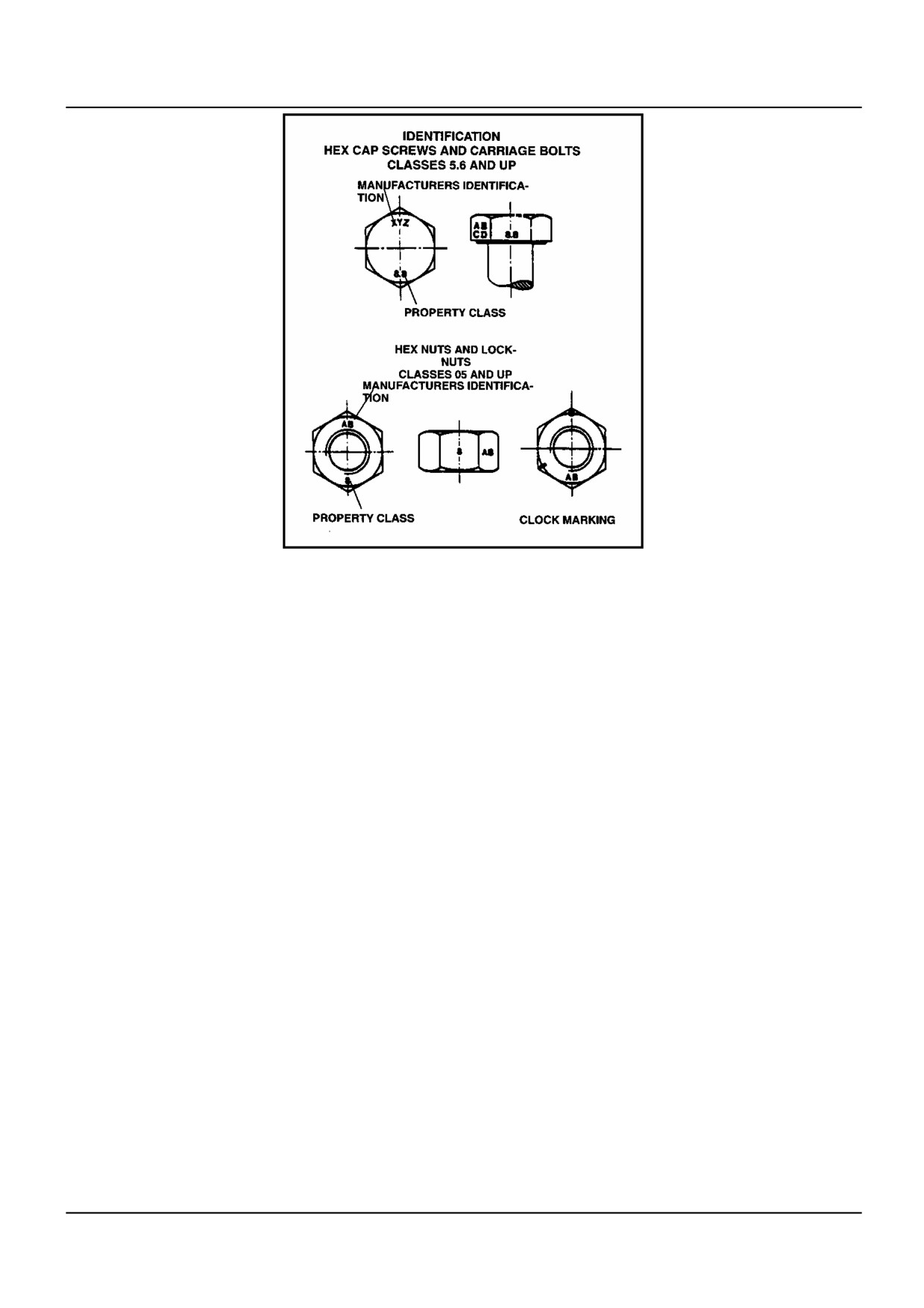
dave5019
3
604_34_001_06 2 4/7/2006
9
INTRODUCTION
Conversion factors ( - A.92.A.21)
Linear
1 mm
=
0.03937 in
1 in
=
25.4 mm
1 Km
=
0.6214 miles
1 mile
=
1.6093 km
1 m
=
3.281 ft
1 ft
=
0.3048 m
Area
1 ha
=
2.471 acre
1 acre
=
0.4047 ha
Volume
1 litre
=
0.0063 barrel
1 barrel
=
158.987 litre
1 litre
=
0.028 US bushel
1 US bushel
=
35.2391 litre
1 litre
=
0.2642 US gal
1 US gal
=
3.7853 litre
1 litre
=
1.057 US quart
1 US quart
=
0.9464 litre
1 mm3
=
0.061 in3
1 in3
=
16387 mm3
Weight
1 kg
=
2.204 pound
1 pound
=
0.4536 kg
Torque
1 Nm
=
0.7376 lbf.ft
1 lbf.ft
=
1.3558 Nm
Power
1 kW
=
1.358 hp
1 hp
=
0.746 kW
Pressure
1 bar
=
14.505 lbf/in2(psi)
1 lbf/in2(psi)
=
0.06894 bar
1 kPa
=
0.145 lbf/in2(psi)
1 lbf/in2(psi)
=
6.894 kPa
1 pa
=
10-5 bar
1 bar
=
100 kPa
Temperature
1 °C
=
((1.8 x ° C) + 32) °F
1 °F
=
(0.56 x (° F -
32)) °F
Flow
1 L/min
=
0.2642 US gpm
1 US gpm
=
3.7853 L/min
604_34_001_06 2 4/7/2006
10
INTRODUCTION
Product identification ( - A.80.A.10)
EXPLANATION OF MACHINE SERIAL NUMBERS
Example : n° 221226001
221226001: The first two digits identify the model within a product line:
CX720 = 20
CX740 = 21
CX760 = 22
CX780 = 23
CX820 = 33
CX840 = 30
CX860 = 31
CX880 = 32
221226001: The third digit indicates the product line. There are 5 product lines in Zedelgem:
CX Combine harvesters:
1
TC/L Combine harvesters:
2
Combine headers:
3
Balers:
4
Forage Harvesters:
5
221226001: These 3 digits indicate the batch in which the machine was made.
221226001: Product line number (1) and batch together form the series number (1226).
221226001: The last 3 digits are a sequential number for each model within a batch.
Summarizing we can say that this machine is the first CX760 of serie 1226.
604_34_001_06 2 4/7/2006
11
REPAIR MANUAL
DISTRIBUTION SYSTEMS
CX720 , CX740 , CX760 , CX780 , CX820 , CX840 , CX860 , CX880
2 4/7/2006
A