New Holland CX720, CX740, CX760, CX780, CX820, CX840, CX860, CX880. Operator's Manual - page 16
Contents
DISTRIBUTION SYSTEMS - A
PRIMARY HYDRAULIC POWER SYSTEM
A.10.A
CX720 , CX740 , CX760 , CX780 , CX820 , CX840 , CX860 , CX880
SECONDARY HYDRAULIC POWER SYSTEM
A.12.A
CX720 , CX740 , CX760 , CX780 , CX820 , CX840 , CX860 , CX880
HYDRAULIC COMMAND SYSTEM
A.14.A
CX720 , CX740 , CX760 , CX780 , CX820 , CX840 , CX860 , CX880
PNEUMATIC SYSTEM
A.20.A
CX720 , CX740 , CX760 , CX780 , CX820 , CX840 , CX860 , CX880
ELECTRICAL POWER SYSTEM
A.30.A
CX720 , CX740 , CX760 , CX780 , CX820 , CX840 , CX860 , CX880
LIGHTING SYSTEM
A.40.A
CX720 , CX740 , CX760 , CX780 , CX820 , CX840 , CX860 , CX880
ELECTRONIC SYSTEM
A.50.A
CX720 , CX740 , CX760 , CX780 , CX820 , CX840 , CX860 , CX880
2 4/7/2006
A
DISTRIBUTION SYSTEMS - A
PRIMARY HYDRAULIC POWER SYSTEM - 10.A
CX720 , CX740 , CX760 , CX780 , CX820 , CX840 , CX860 , CX880
2 4/7/2006
A.10.A / 1
Contents
DISTRIBUTION SYSTEMS - A
PRIMARY HYDRAULIC POWER SYSTEM - 10.A
TECHNICAL DATA
PRIMARY HYDRAULIC POWER SYSTEM
Special tools (A.10.A - D.20.A.40)
4
Hydraulic pump
General specification (A.10.A.20 - D.40.A.10)
5
FUNCTIONAL DATA
PRIMARY HYDRAULIC POWER SYSTEM
Static description (A.10.A - C.30.A.20)
6
Overview (A.10.A - C.40.B.10)
8
Component localisation (A.10.A - C.40.B.20)
11
Hydraulic symbol (A.10.A - C.20.C.20)
21
Hydraulic schema (A.10.A - C.20.B.20)
24
Hydraulic pump
Variable displacement pump - Overview (A.10.A.20.02 - C.40.B.10)
30
Variable displacement pump - Static description (A.10.A.20.02 - C.30.A.20)
31
Variable displacement pump - Dynamic description (A.10.A.20.02 - C.30.A.10)
32
SERVICE
Signal valve
Disassemble (A.10.A.12 - F.10.A.25)
39
Assemble (A.10.A.12 - F.10.A.20)
41
Inspect (A.10.A.12 - F.40.B.01)
42
Stack valve
Disassemble (A.10.A.18 - F.10.A.25)
43
Remove (A.10.A.18 - F.10.A.10)
46
Install (A.10.A.18 - F.10.A.15)
48
Assemble (A.10.A.18 - F.10.A.20)
50
Hydraulic pump
Variable displacement pump - Disassemble (A.10.A.20.02 - F.10.A.25)
53
Variable displacement pump - Remove (A.10.A.20.02 - F.10.A.10)
58
Variable displacement pump - Install (A.10.A.20.02 - F.10.A.15)
60
Variable displacement pump - Assemble (A.10.A.20.02 - F.10.A.20)
62
Variable displacement pump - Inspect (A.10.A.20.02 - F.40.B.01)
66
Variable displacement pump - Test (A.10.A.20.02 - F.40.C.01)
67
DIAGNOSTIC
2 4/7/2006
A.10.A / 2
PRIMARY HYDRAULIC POWER SYSTEM
Troubleshooting (A.10.A - G.40.A.10)
71
Testing (A.10.A - G.40.A.20)
72
Sensing system
E0006-03-Return Filter Bypass Shorted To High Source (A.10.A.95.81 - G.30.B.54)
73
E0024-03-Hydraulic Reservoir Temp Shorted To High Source (A.10.A.95.90 - G.30.B.54)
74
E0024-04-Hydraulic Reservoir Temp Shorted To Low Source (A.10.A.95.90 - G.30.B.53)
75
E0024-05-Hydraulic Reservoir Temp Line Disconnected (A.10.A.95.90 - G.30.B.50)
76
CX720 Series 1206 - 1237, CX740 Series 1206 - 1237, CX760 Series 1206 - 1237, CX780 Series
1206 - 1237, CX820 Series 1206 - 1237, CX840 Series 1206 - 1237, CX860 Series 1206 - 1237,
CX880 Series 1206 - 1237
E0024-05-Hydraulic Reservoir Temp Line Disconnected (A.10.A.95.90 - G.30.B.50)
78
CX720 Series 1238 and above, CX740 Series 1238 and above, CX760 Series 1238 and above,
CX780 Series 1238 and above, CX820 Series 1238 and above, CX840 Series 1238 and above,
CX860 Series 1238 and above, CX880 Series 1238 and above
E0133-03-Hydraulic Reservoir Level Shorted To High Source (A.10.A.95.93 - G.30.B.54)
80
2 4/7/2006
A.10.A / 3
DISTRIBUTION SYSTEMS - PRIMARY HYDRAULIC POWER SYSTEM
PRIMARY HYDRAULIC POWER SYSTEM - Special tools (A.10.A -
D.20.A.40)
DESCRIPTION
NEW HOLLAND
PART NUMBER
(All Markets Except North America)
Blanking Cap 11/16 ORFS
297671
Pressure Gauge 0 - 10 bar (0 - 150 psi)
293241#
Pressure Gauge 0 - 40 bar (0 - 600 psi)
293242#
Pressure Gauge 0 - 250 bar (0 - 5000 psi)
293244#
Remote valve coupling
5101741 or 293449
Quick release adaptor (Female)
291924
Pressure gauge hose
292246#
1/8 NPT fitting to attach hose 292246 to gauge
291927#
Adaptor M10 x 1.0p x 7/16 JIC male (enables use of
297417
gauges with 7/16 JIC hoses if used)
MiniMess (M16x2) Quick attach fitting (procure locally)
Flow Meter 120 ltr/min (0-50 gal/min) minimum (procure
locally)
# Part of hydraulic pressure test kit 292870
O-RING FACE SEAL TUBE ADAPTORS
PARKER HANNIFIN PART NUMBER
Tee Piece (M12x1.5 with 9/16 UNF) - CCLS Pump Load
4M12R870MLOS
sensing
Tee Piece (13/16 UNF fittings) - Steering
8R6MLOS
Elbow (13/16 UNF fittings) - Steering
8ELOS
Quick Release Fitting (9/16 UNF Male) - CCLS Pump
PD34BTL
Load Sensing
Quick Release Fitting (13/16 UNF Male) - Steering
PD38BTL
2 4/7/2006
A.10.A / 4
DISTRIBUTION SYSTEMS - PRIMARY HYDRAULIC POWER SYSTEM
Hydraulic pump - General specification (A.10.A.20 - D.40.A.10)
MAIN HYDRAULIC PUMP
Type
Variable Flow Closed Centre
Load Sensing Piston Pump
Minimum Output @ engine rated speed
114 Ltr/min
30 US gal/min
Standby Pressure
21 bar (305 psi)
Maximum System Pressure
207 bar (3000 psi)
Flow to Steering Motor
36 Ltr/min
9.5 US gal/min
Steering Pressure
186 bar (2700 psi)
2 4/7/2006
A.10.A / 5
DISTRIBUTION SYSTEMS - PRIMARY HYDRAULIC POWER SYSTEM
PRIMARY HYDRAULIC POWER SYSTEM - Static description (A.10.A
- C.30.A.20)
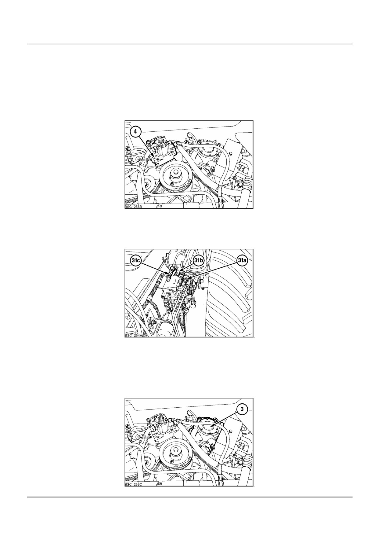
The high pressure circuit operates all of the work hydraulics and steering. The circuit is fed by a closed centre load
sensing variable displacement pump (4). Oil is drawn by the pump, from the main reservoir, shared with the hydro-
static system, through the inline pressure filter to the mainframe valve block.
The oil enters the main frame valve block at the priority valve slice and there the oil is split, dependant on demand, to
the steering valve, which has priority, or to the other hydraulic functions.
The unloading tube control, drum variator control and header height control are served by the main frame stack.
BSC1256B
1
The straw elevator and header reverser, lateral flotation control, reel vertical and horizontal adjustment and reel speed
control are served by the straw elevator stack valve. The straw elevator stack valve is an extension of the main
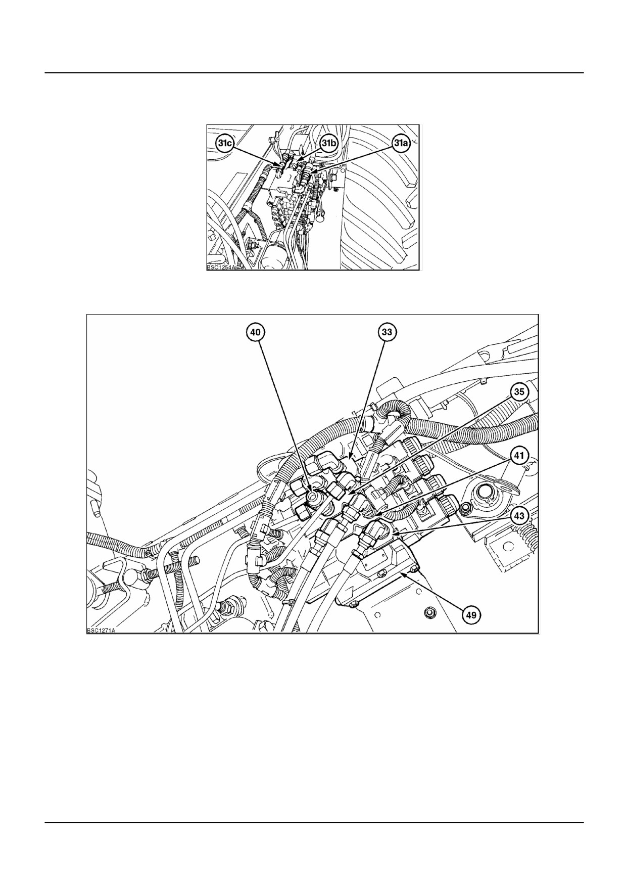
frame stack valve and is connected with pressure (31a), return (31b), and load sensing lines (31c), via quick release
couplings.
BSC1254A
2
The last section of the straw elevator stack valve is a flush valve. This valve allows a very small oil flow through the
stack valves, when no services are being operated, allowing warm oil to bring the stack valve assembly gradually up
to temperature.
The circuit return oil flows through to the return side filter back to the pump or to the reservoir.
The high pressure circuit is linked with the hydrostatic circuit. The hydrostatic pump (3) feeds the hydrostatic circuit.
The charge return and case drain oil flows through to the thermostat and cooler back to the reservoir or high pressure
circuit.
BSC1256C
3
2 4/7/2006
A.10.A / 6
DISTRIBUTION SYSTEMS - PRIMARY HYDRAULIC POWER SYSTEM
The CCLS pump uses the return oil from the hydrostatic system as its charge pressure oil and therefore does not
incorporate a charge pump. The hydrostatic return oil comes into the pump via the oil cooler at the rate of 60 l/min
(63 qts/min). Only when working in high demand conditions does the CCLS pump create an under pressure in the
suction line.
2 4/7/2006
A.10.A / 7
DISTRIBUTION SYSTEMS - PRIMARY HYDRAULIC POWER SYSTEM
PRIMARY HYDRAULIC POWER SYSTEM - Overview (A.10.A -
C.40.B.10)
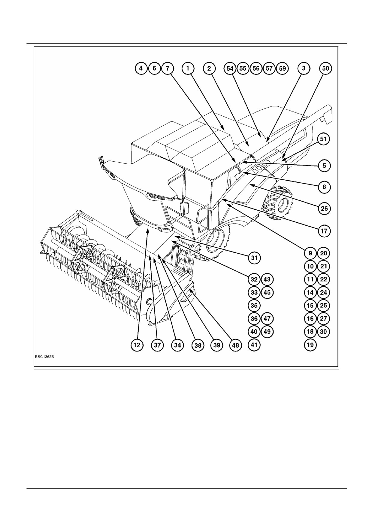
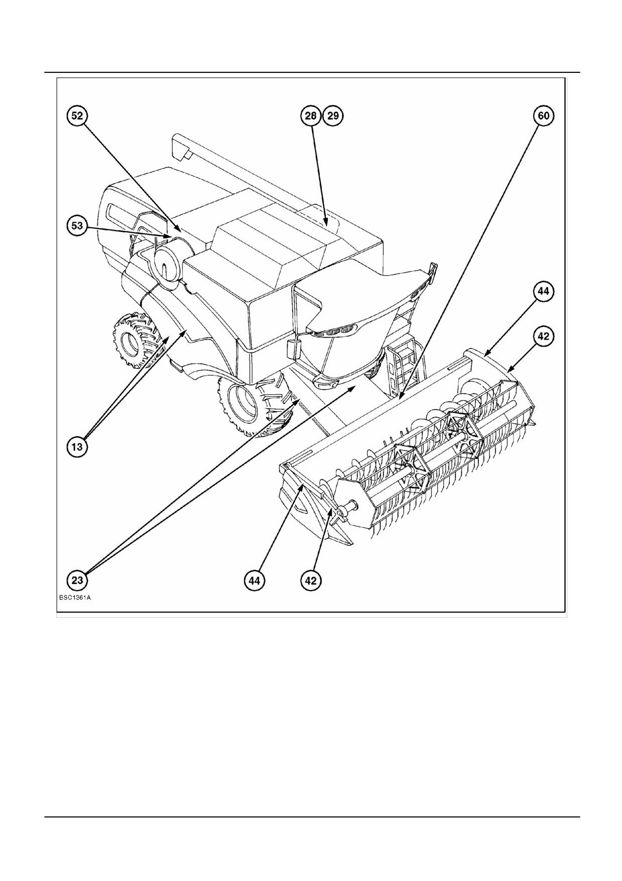
HIGH PRESSURE SYSTEM - COMPONENT LOCATION
1
Engine
2
Gearbox
3
Hydrostatic pump
4
CCLS pump
5
Low pressure gear pump
6
Load sensing valve
7
High pressure relief valve
8
In-line high pressure filter
(197 bar (2856 psi)
9
Priority valve
10
Load sensing lock out valve
11
Load sensing shuttle valve
12
Steering motor
13
Steering cylinders
14
Header height pressure valve
15
High pressure relief valve
16
Accumulator lock out valve
220 bar (3190 psi)
17
Header suspension accumulator
18
Pressure sensor
(70 bar [1015 psi], 0.5 L [17 oz])
19
Header height control valve
20
Header raise valve
21
Header lower valve
22
Header pressure compensation valve
23
Header lift cylinders
24
Electronic control unit
25
Drum variator valve
26
Drum variator adjustment plunger
27
Unloading tube control valve
28
Unloading tube cylinder lock out
29
Unloading tube cylinder
30
Top plate
31
Quick attach couplers
32
Straw elevator stack valve top plate
33
Straw elevator and header reversing valve
34
Straw elevator and header reversing motor
35
Lateral flotation control valve
36
Lateral float pressure compensation valve
37
Lateral flotation cylinder
38
Lateral float accumulator
(80 bar [1160 psi], 0.5 L [17 oz])
39
Lateral float accumulator
40
Lateral float minimum pressure valve
(100 bar [1450 psi], 0.5 L [17 oz])
41
Reel horizontal adjustment valve
42
Reel horizontal adjustment cylinders
43
Reel vertical adjustment valve
44
Reel vertical adjustment cylinders
45
Reel drive / speed adjustment valve
46
(Not used)
47
Reel pressure compensation valve
48
Reel drive motor
49
Flush valve
50
Return filter with by-pass
51
Blocked filter indicator switch
52
Thermostat valve
53
Cooler
54
Suction filter
55
Filler cap with breather
56
Hydraulic oil, minimum level indicator
57
Reservoir
58
Drain hose
59
Temperature sensor
60
Multi-line quick coupler
2 4/7/2006
A.10.A / 8
DISTRIBUTION SYSTEMS - PRIMARY HYDRAULIC POWER SYSTEM
BSC1362B
1
HIGH PRESSURE SYSTEM - COMPONENT LOCATION
2 4/7/2006
A.10.A / 9
DISTRIBUTION SYSTEMS - PRIMARY HYDRAULIC POWER SYSTEM
BSC1361A
2
HIGH PRESSURE SYSTEM - COMPONENT LOCATION
2 4/7/2006
A.10.A / 10
DISTRIBUTION SYSTEMS - PRIMARY HYDRAULIC POWER SYSTEM
PRIMARY HYDRAULIC POWER SYSTEM - Component localisation
(A.10.A - C.40.B.20)
NOTE: The reference numbers used in the illustrations and text relate to the identification numbers used on the High
Pressure Circuit Diagram, PRIMARY HYDRAULIC POWER SYSTEM - Hydraulic schema (A.10.A-C.20.B.20).
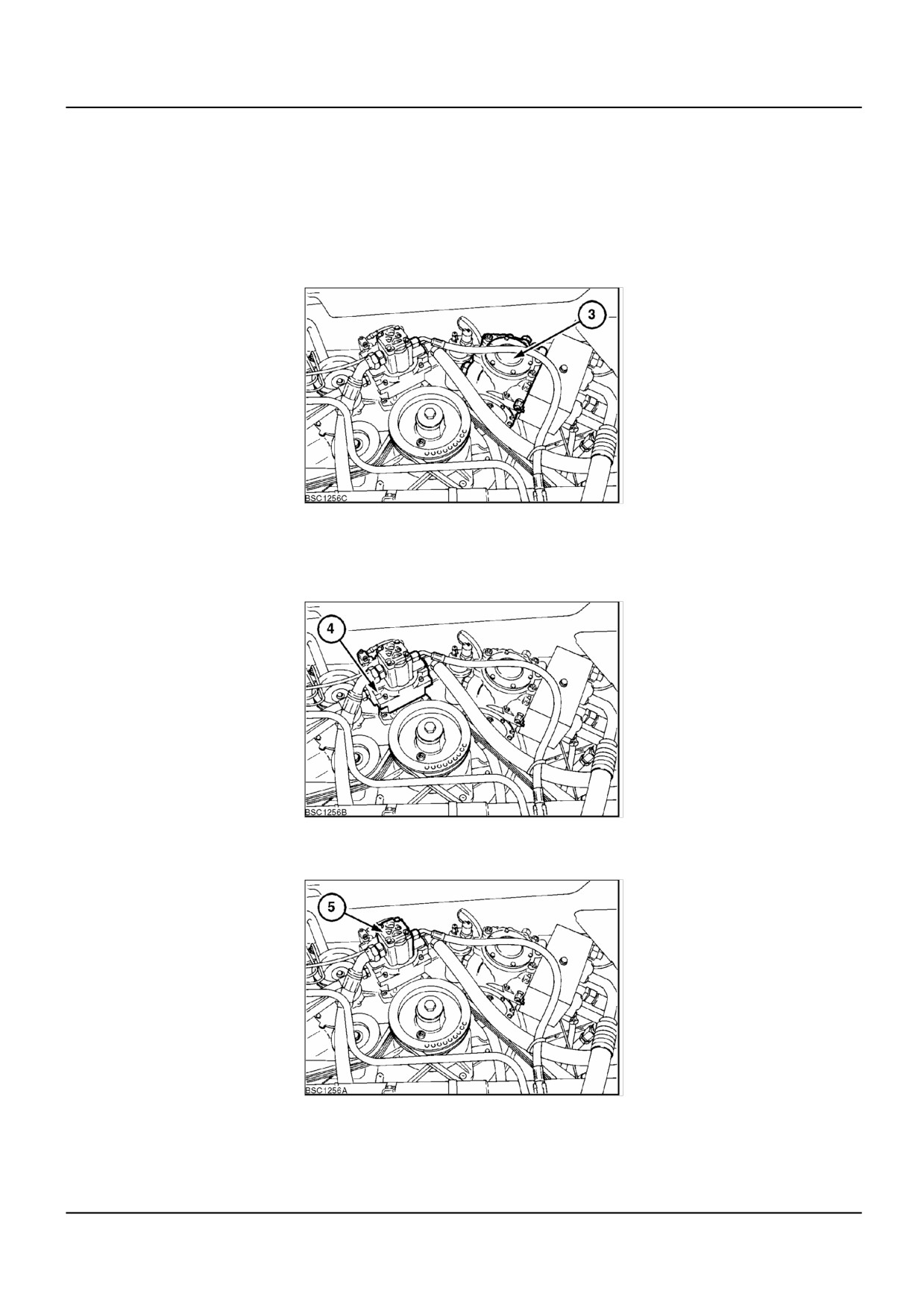
(3) Hydrostatic Pump
Although not part of the high pressure system, the return oil from the hydrostatic motors is used as charge pressure
oil for the high pressure CCLS pump.
BSC1256C
1
(4) Closed Centre Load Sensing (CCLS) Pump
Provides the oil for the high pressure system. Will supply the pressure as demanded by the services in use due to its
load sensing and variable displacement capability. Has the advantage over a fixed pump in that it reduces the engine
power absorbed when maximum pump flow is not required.
BSC1256B
2
(5) Low Pressure Gear Pump
Totally separate from the high pressure system. Mounted on the CCLS pump from where it takes its drive.
BSC1256A
3
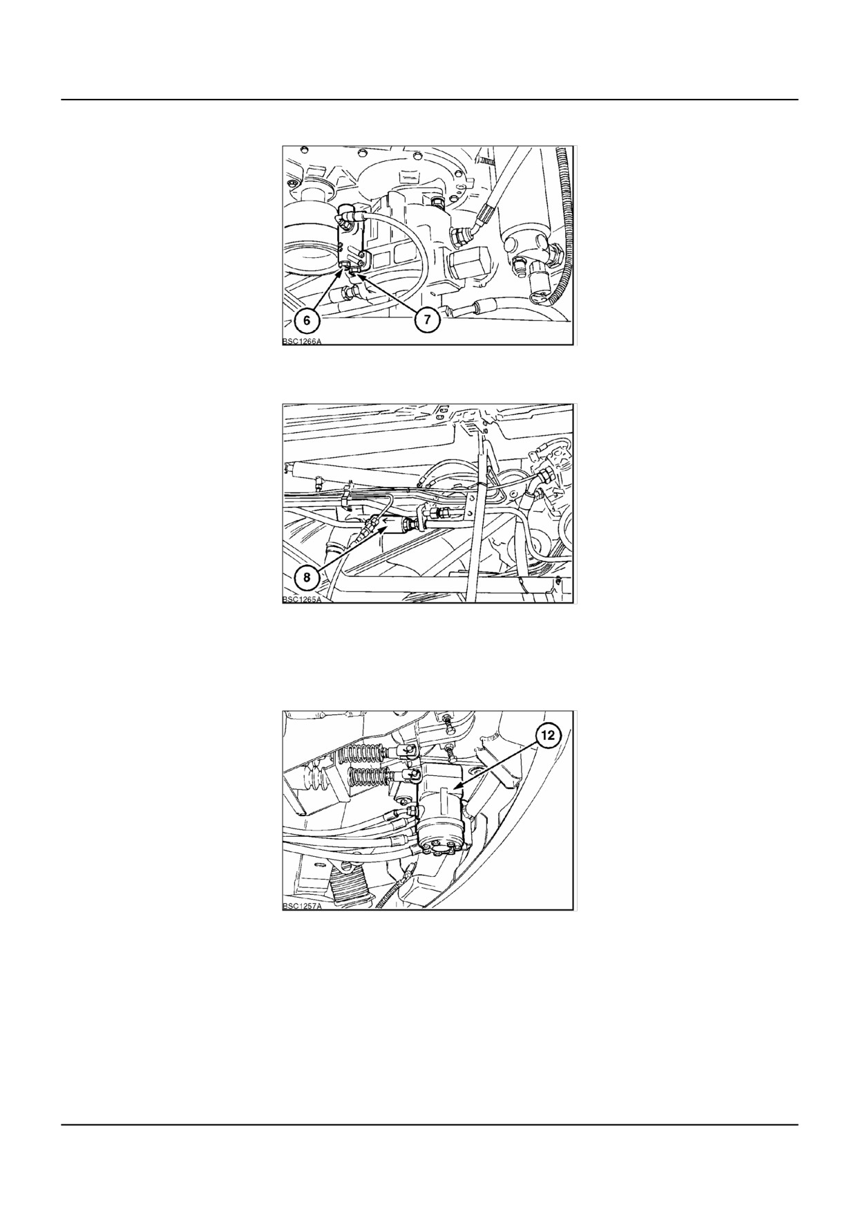
(6) Load Sensing Valve (mounted on CCLS pump)
(7) High Pressure Relief Valve (mounted on CCLS pump)
Output from the CCLS pump is determined by adjusting the angle of the swash plate. The load sensing valve senses
the circuit operating pressure and adjusts the swash plate angle to control pump output. If pump output rises to 197
2 4/7/2006
A.10.A / 11
DISTRIBUTION SYSTEMS - PRIMARY HYDRAULIC POWER SYSTEM
bar (2857 psi) the high pressure relief valve over rides the load sensing valve and adjusts the swash plate angle to
limit maximum system pressure.
BSC1266A
4
(8) In Line High Pressure Filter
A replaceable filter located between the CCLS pump output and the high pressure system priority valve.
BSC1265A
5
(12) Steering Motor
Supplied oil via the priority valve in the main frame stack. The steering motor directs and controls oil to the steering
cylinders, based on input via movement of the steering wheel.
There are 2 different motors available. An OSPF 315 cc load sensing fixed capacity unit for North America only and
an OSPQ 160/320 cc load sensing variable capacity unit for all other locations.
BSC1257A
6
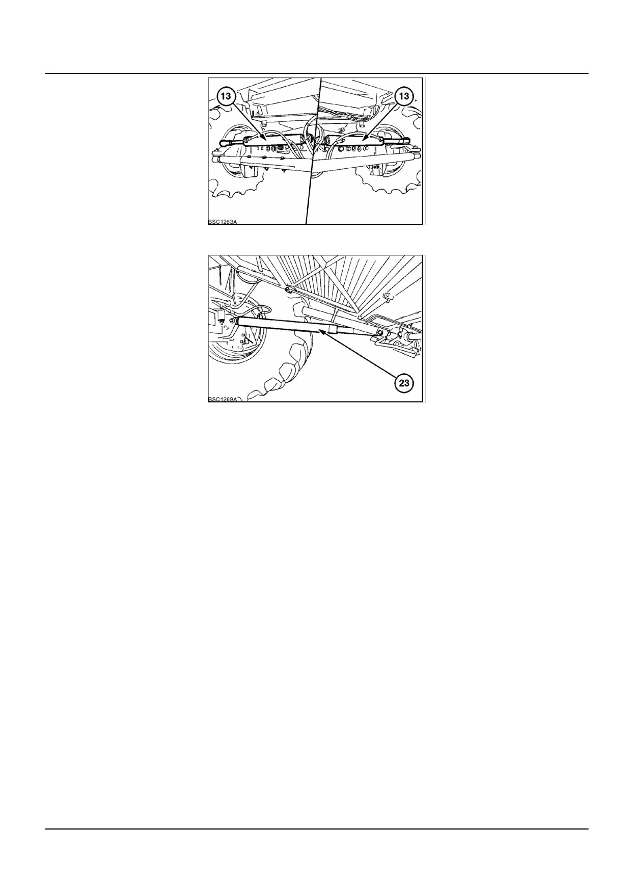
(13) Steering Cylinders
2 4/7/2006
A.10.A / 12
DISTRIBUTION SYSTEMS - PRIMARY HYDRAULIC POWER SYSTEM
BSC1263A
7
(23) Header Lift Cylinder
BSC1269A
8
2 4/7/2006
A.10.A / 13
DISTRIBUTION SYSTEMS - PRIMARY HYDRAULIC POWER SYSTEM
BSC1270A
9
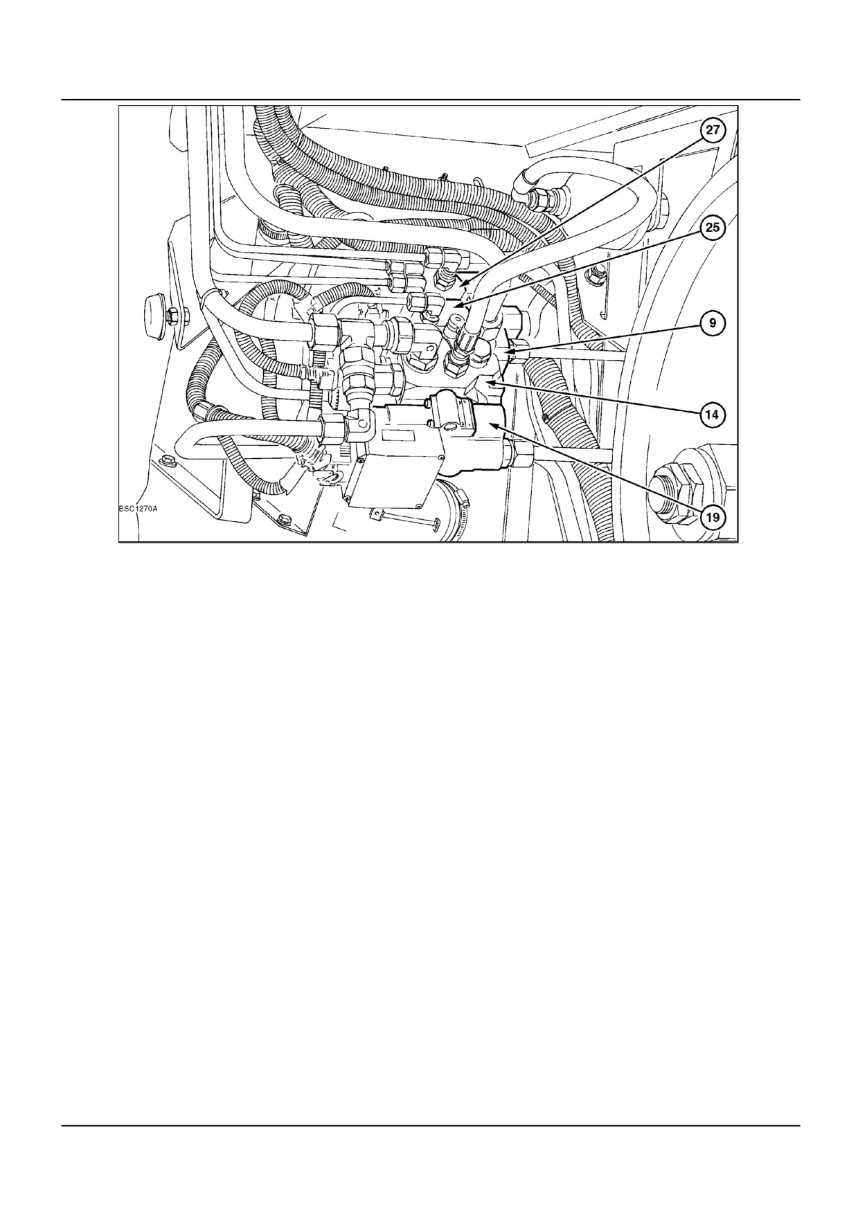
Main Frame Stack Valve Assembly
(9)
Priority Valve
Located in the main frame stack valve, receives the output oil from the CCLS pump and will
provide steering with the priority for oil. Actuated by pressure within the load sense lines.
(10)
Load Sense / Steering Relief Valve
Located in the priority valve. When the pressure in the load sense circuit or steering circuit
exceeds a preset value the relief valve will blow and then maintain a maximum pressure in
the load sense or steering circuits.
(11)
Load Sensing Shuttle Valve
Located in each valve slice. Allows the function with the highest pressure demand to send
sensing pressure to the load sensing valve on the CCLS pump.
(14)
Header Height Pressure Valve
Controls the pressure within the header height cylinders.
Contains the high pressure relief valve (15), accumulator lock out valve (16) and pressure
sensor (18).
(16)
Accumulator Lock Out Valve
Solenoid controlled valve which isolates the accumulator from the raise and lower circuit.
(19)
Header Height Control Valve
Controls the raising and lowering of the header. Contains the PWM raise and lower valves
and compensation valve.
(20)
Header Raise Valve
A PWM controlled valve, allows pressure oil to the raise cylinder.
(21)
Header Lower Valve
A PWM controlled valve, allows oil to be released from the lift cylinders under control.
(22)
Header Pressure Compensation Valve
Ensures that height raise speed is consistent in all operating conditions, provides
compensation to pressure spikes in the system.
2 4/7/2006
A.10.A / 14
DISTRIBUTION SYSTEMS - PRIMARY HYDRAULIC POWER SYSTEM
(25)
Drum Variator Control Valve
Controls the plunger within the variator drum drive unit to provide adjustable variator speed.
Solenoid operated valves either allow pressure oil to provide a speed increase or release
oil pressure to decrease speed.
(27)
Unloading Tube Control Valve
Controls the unloading tube cylinder. Consists of two electrically operated solenoid valves.
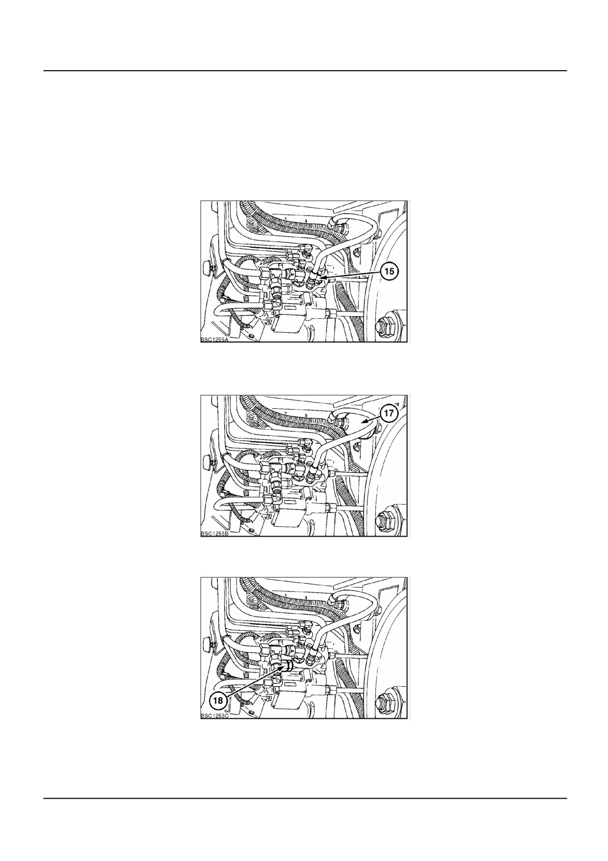
(15) High Pressure Relief Valve
This acts as a shock relief valve for the header. Sudden rises in pressure, as felt at the lift cylinders, are relieved
through this valve.
BSC1255A
10
(17) Header Suspension Accumulator
Absorbs the slight movement to the header encountered during normal operating. The accumulator is rated at 70 bar
pressure with a volume of 0.5 L.
BSC1255B
11
(18) Pressure Sensor
Measures the hydraulic pressure within the header circuit. Sends a signal to the header electronic control unit.
BSC1255C
12
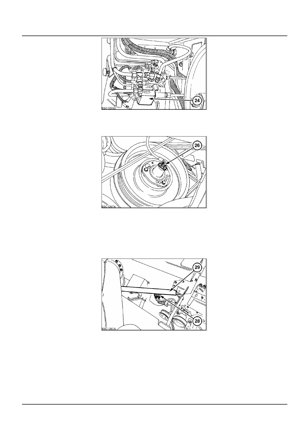
(24) Electronic Control Unit
Controls the header height via the PWM controlled raise and lower solenoids, based on the signal sent by the operator
cab controls.
2 4/7/2006
A.10.A / 15
DISTRIBUTION SYSTEMS - PRIMARY HYDRAULIC POWER SYSTEM
BSC1255D
13
(26) Drum Variator Adjustment Plunger
Operated via the drum variator valve, the plunger is a hydraulic cylinder that operates a floating disc within the variator
assembly to alter variator speed.
BSC1267A
14
(28) Unloading Tube Lockout Block
Isolates the unload cylinder from the control valve and pipework. Ensures that the unload tube will remain in the
required position until the control valve is activated. When pressure oil is applied to the lock out block, a bleed line is
supplied to the opposite side which releases the lock valve and allows oil to escape. When the pressure oil is removed
the lock out valves close and prevent cylinder movement.
(29) Unload Tube Cylinder
Operates the unload arm, controlled by the unload tube control valve and lock out block.
BSC1260A
15
(31) Quick Attach Couplers
Connects the main stack valve block to the header valve block assembly.
(31a) = Pressure supply
(31b) = Return line
(31c) = Load sensing line
2 4/7/2006
A.10.A / 16
DISTRIBUTION SYSTEMS - PRIMARY HYDRAULIC POWER SYSTEM
NOTE: The return line must always be correctly connected. The quick attach coupler of the return line incorporates
check valves allowing flow back to the main frame stack valve. If the engine is started with the return line disconnected
oil will escape from the valve block.
BSC1254A
16
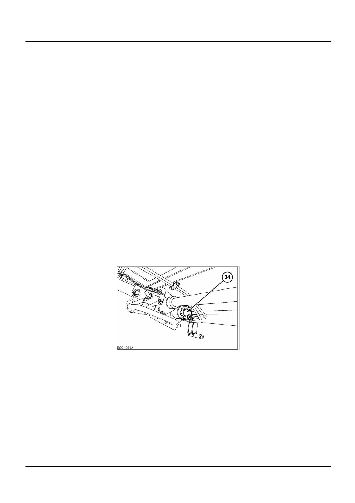
BSC1271A
17
Straw Elevator Valve Stack
(33) Straw Elevator and Header Reversing Valve
Controls the motor for the straw elevator and header reverser. Contains two electrically controlled solenoids which
move a spool to obtain forward, reverse or a float position on the motor.
(35) Lateral Flotation Control Valve
Controls the lateral flotation cylinder. Consists of two electrically controlled solenoids, a pressure compensation valve
and a lock out valve.
2 4/7/2006
A.10.A / 17
DISTRIBUTION SYSTEMS - PRIMARY HYDRAULIC POWER SYSTEM
(36) Lateral Float Pressure Compensation Valve
Ensures that lateral float operation is consistent in all operating conditions, provides compensation to pressure spikes
in the system.
(40) Lateral Float Minimum Pressure Valve
This is a resistant valve and prevents the header from jerky counterclockwise movement and jerky operation when
the cylinder is retracted. This is necessary because of the non-North American header being heavier on the left hand
side. The valve is set at approximately 60 bar (870 psi).
(41) Reel Horizontal Adjustment Valve
(42) Reel Horizontal Adjustment Cylinders
Controls the horizontal position of the reel. The valve consists of two electrically operated solenoids and a lock out
valve.
(43) Reel Vertical Adjustment Valve
Controls the vertical adjustment cylinders. Consists of two electrically operated solenoids and a lock out valve.
(44) Reel Vertical Adjustment Cylinders
Two cylinders, a master and a slave, supplied oil from the vertical adjustment valve (43). The slave is powered by the
rod end oil of the master cylinder.
(49) Flush Valve
When there are no services in use, charge pressure oil is allowed to join the return circuit through the flush valve.
This function allows a flow of oil through the header stack valve thereby circulating warm oil through the valves.
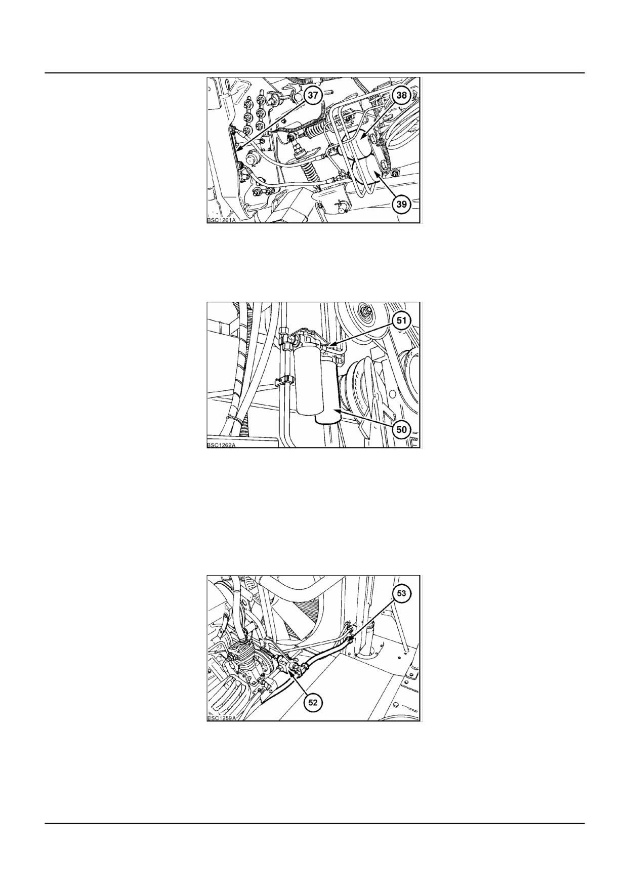
(34) Straw Elevator and Header Reversing Motor
BSC1268A
18
(37) Lateral Flotation Cylinder
Adjusts header angle in relation to the combine.
(38) Lateral Float Accumulator - Lowering side - 50 bar (725 psi)
(39) Lateral Float Accumulator - Raise Side - 75 bar (1088 psi)
2 4/7/2006
A.10.A / 18
DISTRIBUTION SYSTEMS - PRIMARY HYDRAULIC POWER SYSTEM
BSC1261A
19
(50) Return Filter with Bypass
(51) Return Filter Element Differential Drop Indicator.
Electrical switch to indicate pressure differential as the filter becomes clogged during service.
BSC1262A
20
(52) Thermostat Valve
Cooler bypass valve, directs cold oil away from the cooler and back into the return circuit. As the oil progressively
warms up the oil is then allowed, by the thermostat valve, through the cooler. A relief valve is incorporated to allow
direct routing to the return circuit when the pressure is too high for the system to cope with.
(53) Cooler
Hydraulic oil cooler, mounted with the engine cooler on the right hand side of the vehicle.
BSC1259A
21
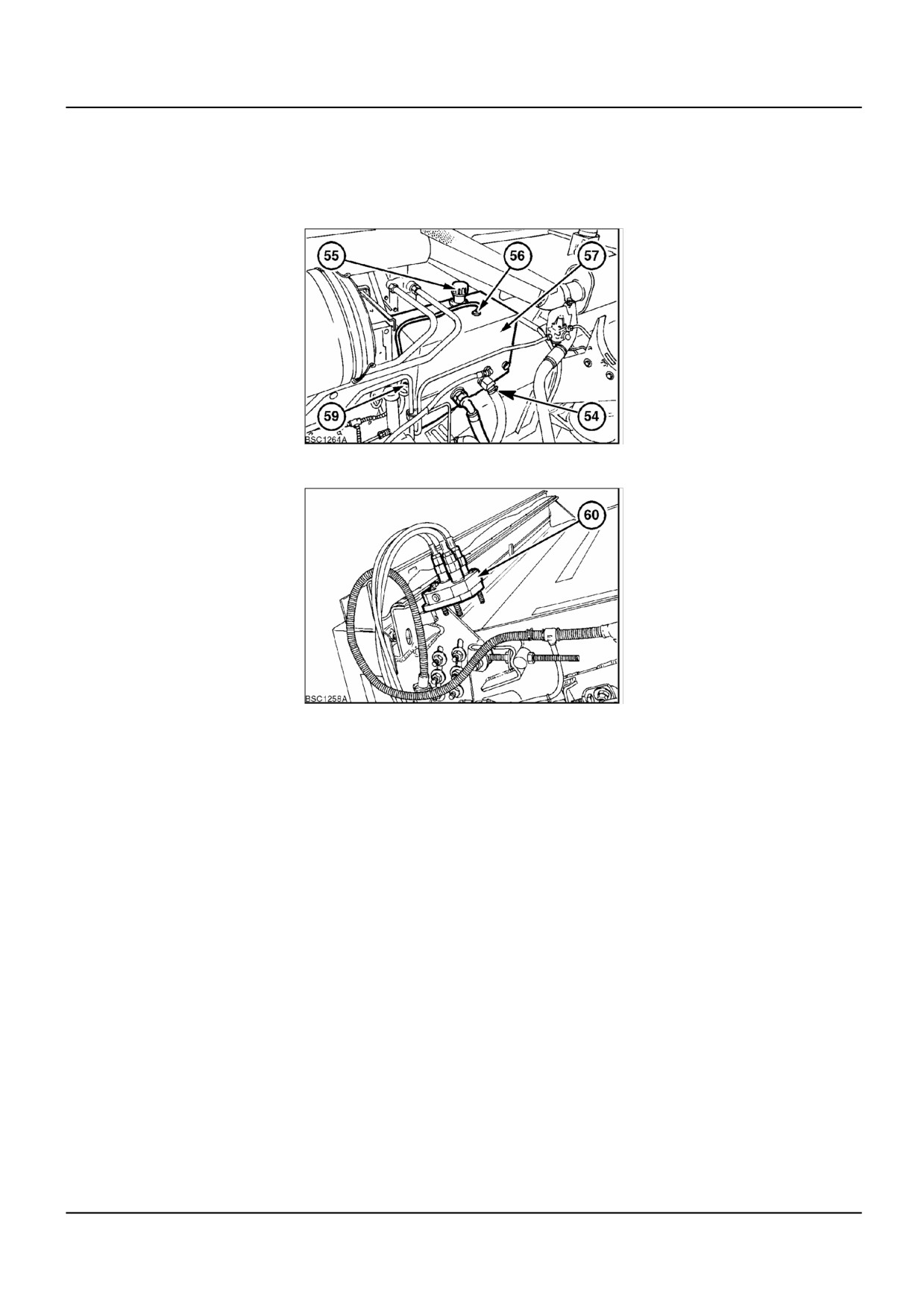
(54) Suction Filter
Located in the base of the reservoir in the suction line supplying the hydrostatic pump.
(55) Filler Cap With Breather
(56) Minimum level electrical switch for hydraulic oil reservoir. (high pressure system and hydrostatic system oil).
2 4/7/2006
A.10.A / 19
DISTRIBUTION SYSTEMS - PRIMARY HYDRAULIC POWER SYSTEM
(57) Hydraulic Oil Reservoir (high pressure system and hydrostatic system oil).
(59) Temperature Sensor
Measures hydraulic oil temperature, high oil temperature indicated at 85 °C (185 °F).
BSC1264A
22
(60) Header Hoses Quick Release Coupling.
BSC1258A
23
2 4/7/2006
A.10.A / 20
DISTRIBUTION SYSTEMS - PRIMARY HYDRAULIC POWER SYSTEM
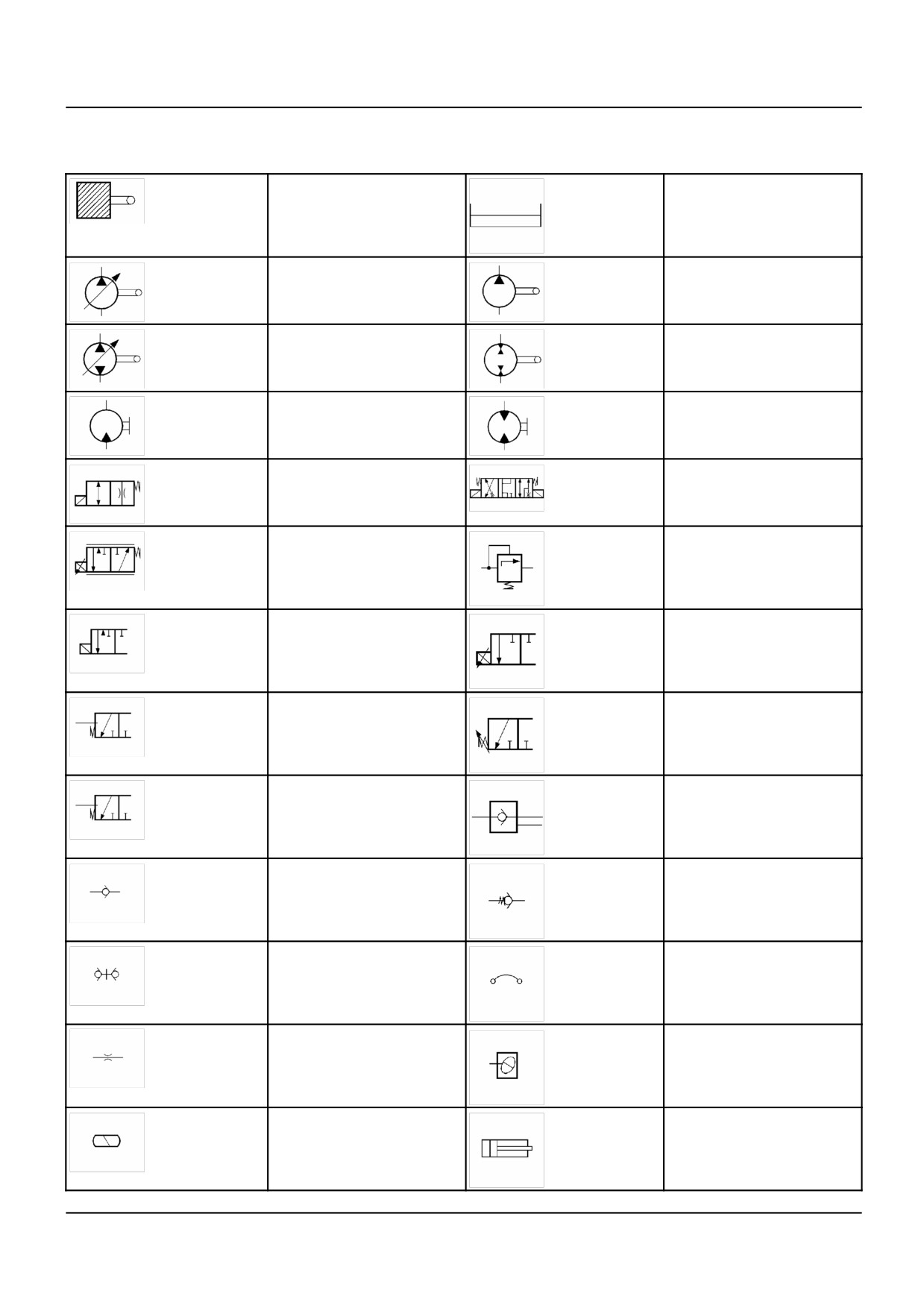
PRIMARY HYDRAULIC POWER SYSTEM - Hydraulic symbol (A.10.A
- C.20.C.20)
Engine
Reservoir
Hydraulic pump, direction
Hydraulic pump single
with variable displacement
direction fixed displacement
Hydraulic pump, directional
Steering motor
with displacement
(bi-directional)
Motor, single direction fixed
Motor bi-directional fixed
displacement
displacement
2 position valve
3 position valve
Proportional (PWM) valve
Pressure relief valve
Solenoid controlled
Proportional solenoid
movement
movement (Pulse Width
Modulation)
Movement by or against
Movement by or against
spring tension
adjustable spring tension
Movement by or against oil
Lock-out valve
pressure
Non return valve
Non return valve, pressure
controlled
Quick coupler with non
Flexible hose
return valve
Restrictor
Thermostat
Hydro-pneumatic
Cylinder
accumulator
2 4/7/2006
A.10.A / 21
DISTRIBUTION SYSTEMS - PRIMARY HYDRAULIC POWER SYSTEM
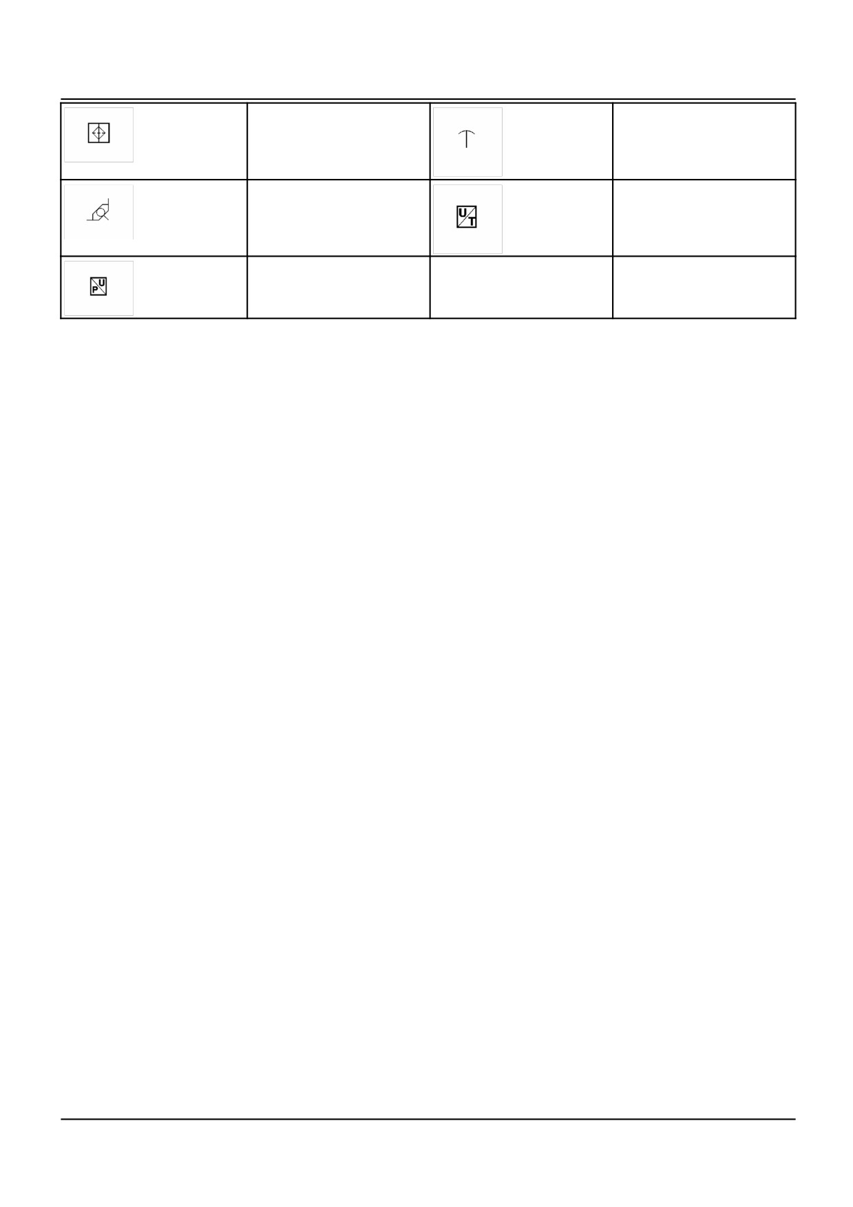
Filter
Filter opening
Shuttle valve
Temperature sender
Pressure sensor
2 4/7/2006
A.10.A / 22
DISTRIBUTION SYSTEMS - PRIMARY HYDRAULIC POWER SYSTEM
PRIMARY HYDRAULIC POWER SYSTEM - Hydraulic schema
(A.10.A - C.20.B.20)
High Pressure circuit diagram
1a series 1206 - 1479
1
Engine
31
Quick attach couplers
2
Gearbox
32
Straw elevator stack valve top plate
3
Hydrostatic pump
33
Straw elevator and header reversing valve
4
CCLS pump
34
Straw elevator and header reversing motor
5
Low pressure gear pump
35
Lateral flotation control valve
6
Load sensing valve
36
Lateral float pressure compensation valve
7
High pressure relief valve
37
Lateral flotation cylinder
(197 bar (2856 psi)
8
In-line high pressure filter
38
Lateral float accumulator
(80 bar [1160 psi], 0.5 L [17 oz])
9
Priority valve
39
Lateral float accumulator
(100 bar [1450 psi], 0.5 L [17 oz])
10
Load sensing lock out valve
40
Lateral float minimum pressure valve
11
Load sensing shuttle valve
41
Reel horizontal adjustment valve
12
Steering motor
42
Reel horizontal adjustment cylinders
13
Steering cylinders
43
Reel vertical adjustment valve
14
Header height pressure valve
44
Reel vertical adjustment cylinders
15
High pressure relief valve
45
Reel drive / speed adjustment valve
220 bar (3190 psi)
16
Accumulator lock out valve
46
(Not used)
17
Header suspension accumulator
47
Reel pressure compensation valve
(70 bar [1015 psi], 0.5 L [17 oz])
18
Pressure sensor
48
Reel drive motor
19
Header height control valve
49
Flush valve
20
Header raise valve
50
Return filter with by-pass
21
Header lower valve
51
Blocked filter indicator switch
22
Header pressure compensation valve
52
Thermostat valve
23
Header lift cylinders
53
Cooler
24
Electronic control unit
54
Suction filter
25
Drum variator valve
55
Filler cap with breather
26
Drum variator adjustment plunger
56
Hydraulic oil, minimum level indicator
27
Unloading tube control valve
57
Reservoir
28
Unloading tube cylinder lock out
58
Drain hose
29
Unloading tube cylinder
59
Temperature sensor
30
Top plate
60
Multi-line quick coupler
2 4/7/2006
A.10.A / 24