New Holland CX720, CX740, CX760, CX780, CX820, CX840, CX860, CX880. Operator's Manual - page 13
SECTION 4 - LUBRICATION AND MAINTENANCE
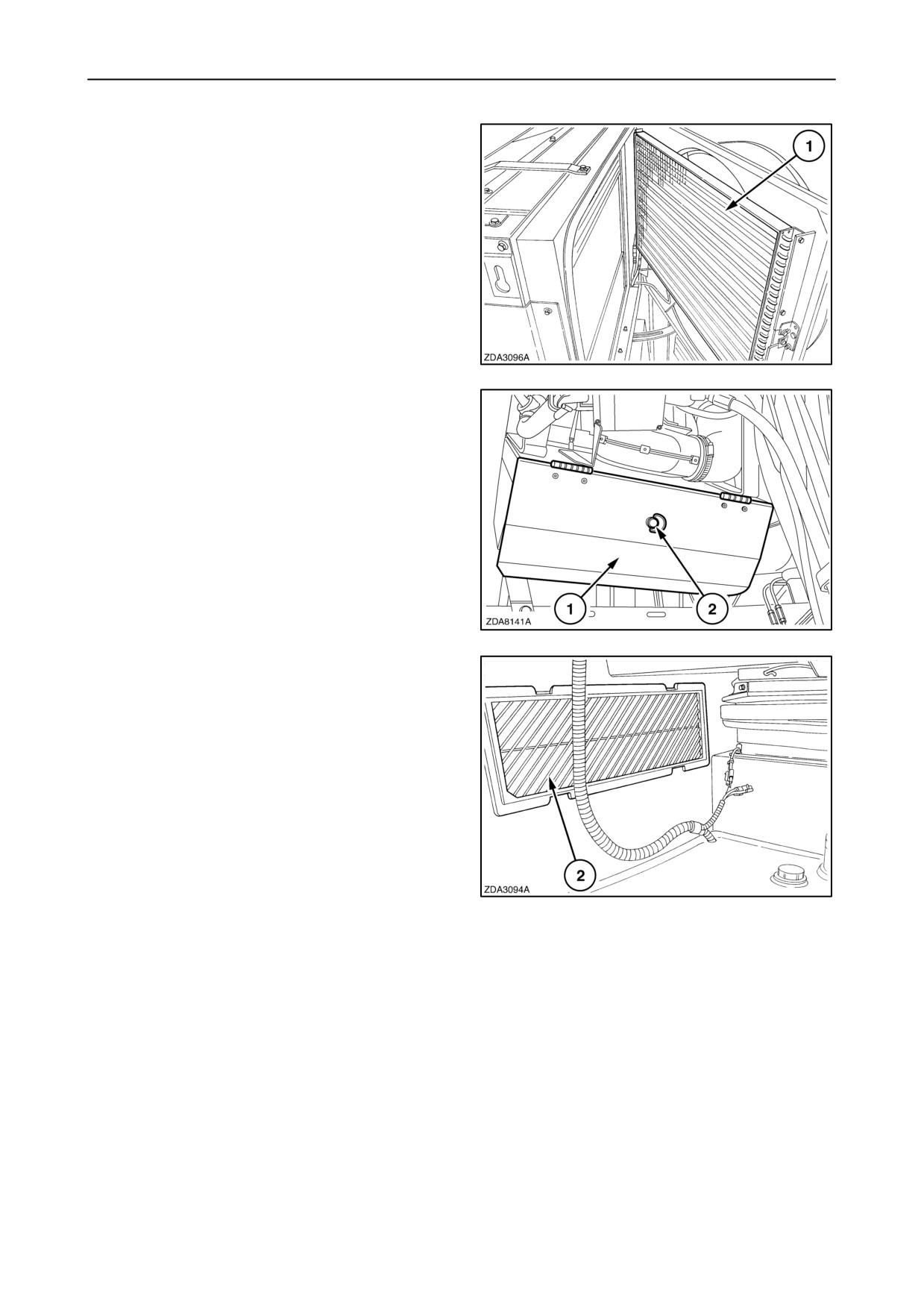
Condenser
Regularly inspect and clean the condenser 1 with
compressed air.
To gain access to clean the condenser: refer to
”Rotary dust screen and cooling system” in this
section.
220
Fresh air intake grill
The fresh air intake grill is located behind the
left-hand front shield.
To clean the dust on the fresh air intake grill, open
door 1 on the fresh air intake box by turning the latch
2.
221
Recirculation filter
The recirculation filter 2 is located in the cab, on the
right-hand side of the operator ’s seat.
Clean the cab air filter regularly and, in extremely
dusty conditions, daily.
To clean remove the recirculation grill.
NOTE: To easily remove, push up the grill and rotate
it out of the opening.
222
4-118
SECTION 4 - LUBRICATION AND MAINTENANCE
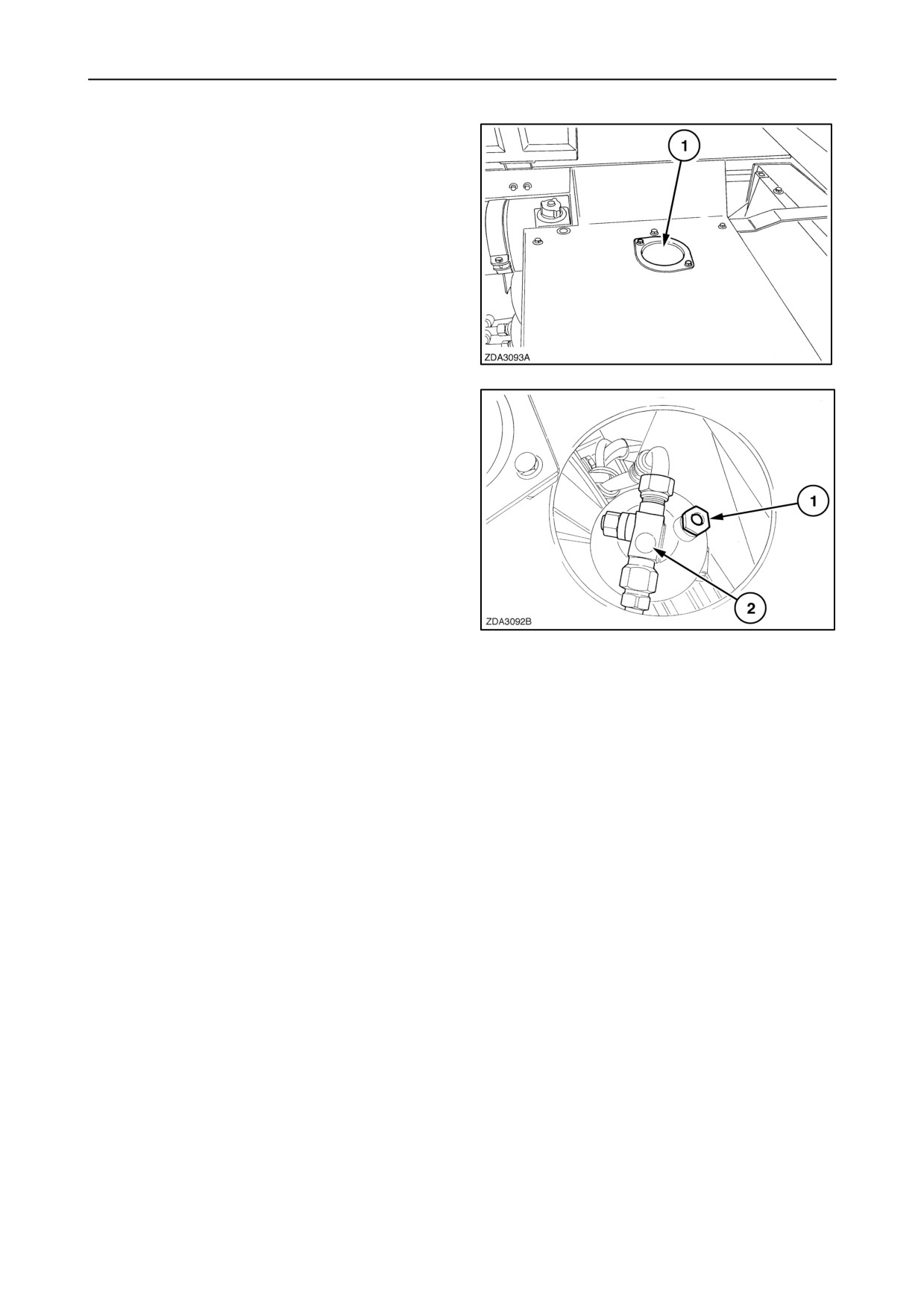
Filter-drier
The filter-drier is located on the right hand side of the
engine cover.
Remove cover 1 (if installed) to view the filter-drier.
223
A sight glass 2 and a ring-shaped moisture indicator
1 serve for determining the condition of the R 134a
gas.
• If the refrigerant is without air bubbles, then the
refrigerant condition is good.
• If the glass shows a milky refrigerant: good
condition in ambient temperature.
• If air bubbles are visible: lack of refrigerant.
• If the moisture indicator is blue: filter and
refrigerant are in good condition.
• If the moisture indicator is red: this is an indication
224
of too much moisture, the filter-drier has to be
replaced.
• If the moisture indicator is brown or black: too
much contamination: filter-drier has to be
replaced.
NOTE: The filter-drier must always be replaced when
the air circuit has been opened.
If the filter-drier needs to be replaced, or if the air
conditioning system needs repair, contact your local
dealer.
4-119
SECTION 4 - LUBRICATION AND MAINTENANCE
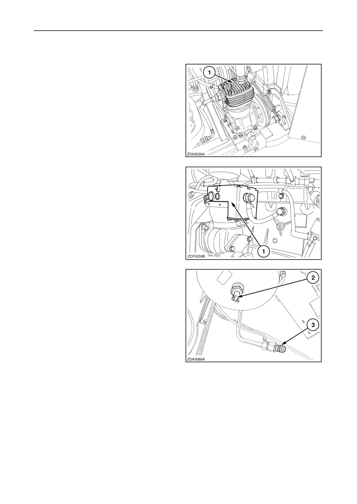
AIR COMPRESSOR (IF INSTALLED)
• CNH engine:
The air compressor 1 is installed near the engine and
needs no further maintenance.
225
• Iveco engine:
The air compressor 1 is installed onto the engine and
needs no further maintenance.
226
Every 50 operating hours, drain the condensated
water from the air reservoir through cock 2.
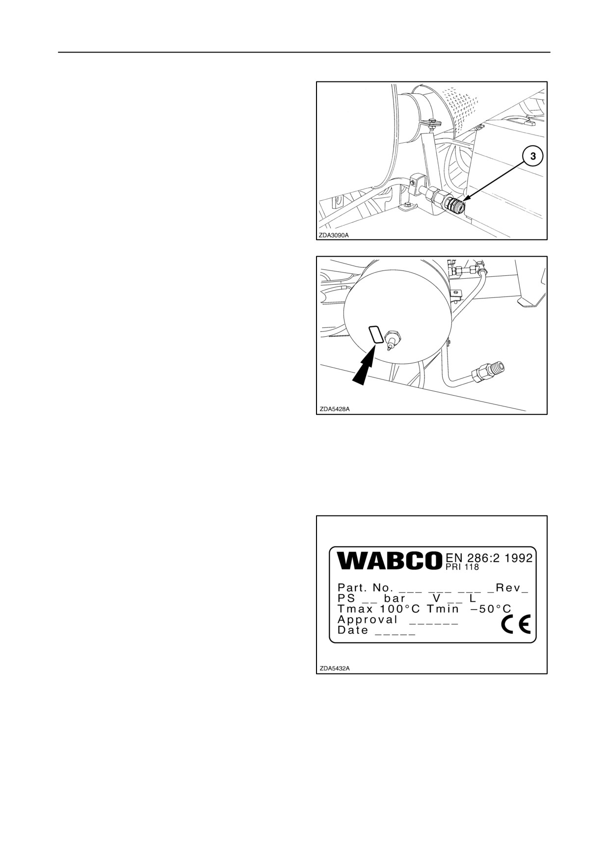
Two unions 3 are installed to attach pneumatic ser-
vice tools and for cleaning purposes.
The inner thread of the union is 1/2 GAZ CYL.
One is located under the air reservoir.
227
4-120
SECTION 4 - LUBRICATION AND MAINTENANCE
A second is located at the top of the straw hood near
the oil reservoir.
228
Air reservoir specification
(according to European Directive 87/404/EEC)
• Trade mark: Wabco
• Type: ”60 l”
• Maximum operating pressure: 10 bar
(145.1 PSI)
• Maximum operating temperature: +100_ C
(212_ F)
229
• Minimum operating temperature: - 50_ C
(-58_ F)
• Capacity: 60 litres (15.85 US gal)
• Approval date: see cold stamping on the air
reservoir.
IMPORTANT: For France, the air reservoir must be
reapproved (technical control) every 5 years.
The owner has to take the necessary actions to have
the reservoir retested before the expiry date which is
the approval date + 5 years.
230
4-121
SECTION 4 - LUBRICATION AND MAINTENANCE
MAINTENANCE SCHEDULE
Service to be performed before the first start-off
Section
1. Check wheel nut torques
SPECIFICATIONS
2. Check all chain and belt tensions
LUBRICATION AND MAINTENANCE
3. Check all tyre pressures
SPECIFICATIONS
4. Check brake fluid level
LUBRICATION AND MAINTENANCE
5. Check engine oil level
LUBRICATION AND MAINTENANCE
6. Check coolant level (shunt tank)
LUBRICATION AND MAINTENANCE
7. Check hydraulic/hydrostatic oil level
LUBRICATION AND MAINTENANCE
8. Check engine gearbox oil level
LUBRICATION AND MAINTENANCE
9. Check fuel level
LUBRICATION AND MAINTENANCE
10. Grease all zerks
LUBRICATION AND MAINTENANCE
Run-in period
Service to be performed
Section
First week: daily
Check wheel nut torques
SPECIFICATIONS
After first 100 hours
Change engine oil+filter
LUBRICATION AND MAINTENANCE
Change hydraulic filter
LUBRICATION AND MAINTENANCE
Change hydrostatic filter
LUBRICATION AND MAINTENANCE
Change engine gearbox filter
LUBRICATION AND MAINTENANCE
Change traction gearbox oil
LUBRICATION AND MAINTENANCE
Change final drives gearbox oil
LUBRICATION AND MAINTENANCE
Change unloading drive gearbox oil
LUBRICATION AND MAINTENANCE
Check unloading tube drive gearbox oil
LUBRICATION AND MAINTENANCE
Change bubble-up gearbox oil
LUBRICATION AND MAINTENANCE
Lubricate all chains
LUBRICATION AND MAINTENANCE
Daily service to be performed
Section
1.
Check engine oil level
LUBRICATION AND MAINTENANCE
2.
Check hydraulic/hydrostatic oil level
LUBRICATION AND MAINTENANCE
3.
Check all chain and belt tensions
LUBRICATION AND MAINTENANCE
4.
Check coolant level (shunt tank)
LUBRICATION AND MAINTENANCE
5.
Clean cab air filter
LUBRICATION AND MAINTENANCE
6.
Check fuel level
LUBRICATION AND MAINTENANCE
7.
Clean stone trap
FIELD AND SITE OPERATIONS
8.
Drain water from fuel system prefilter/water
LUBRICATION AND MAINTENANCE
separator
4-122

SECTION 4 - LUBRICATION AND MAINTENANCE
50 hour service to be performed
Section
1.
Perform the 50 hour grease zerk service
LUBRICATION AND MAINTENANCE
2.
Check wheel nut torques
SPECIFICATIONS
3.
Check steering ball joints
LUBRICATION AND MAINTENANCE
4.
Check and clean air conditioning condenser
LUBRICATION AND MAINTENANCE
5.
Check and clean air conditioning evaporator
LUBRICATION AND MAINTENANCE
6.
Check air conditioning filter-drier
LUBRICATION AND MAINTENANCE
7.
Check tyre pressure
SPECIFICATIONS
8.
Check drum concave setting
FIELD AND SITE OPERATIONS
9.
Check electrolyte level in batteries
LUBRICATION AND MAINTENANCE
10. Check the tension of the grain elevator chain
LUBRICATION AND MAINTENANCE
11. Check the clear bowl of the supply pump
LUBRICATION AND MAINTENANCE
100 hour service to be performed
Section
1.
Perform the 50 hour service (see above)
LUBRICATION AND MAINTENANCE
2.
Perform the 100 hour grease zerk service
LUBRICATION AND MAINTENANCE
200 hour service to be performed
Section
1.
Perform the 50 hour service (see above)
LUBRICATION AND MAINTENANCE
2.
Perform the 100 hour grease zerk service
LUBRICATION AND MAINTENANCE
3.
Perform the 200 hour grease zerk service
LUBRICATION AND MAINTENANCE
4.
Lubricate threaded rods and pivot points
LUBRICATION AND MAINTENANCE
5.
Check steering ball joints, wheel spindles, tie rods
LUBRICATION AND MAINTENANCE
and steering hydraulic components
4-123
SECTION 4 - LUBRICATION AND MAINTENANCE
300 hour service to be performed
Section
1. Perform the 50 hour service (see above)
LUBRICATION AND MAINTENANCE
2. Perform the 100 hour grease zerk service
LUBRICATION AND MAINTENANCE
3. Check and clean foot and parking brake
LUBRICATION AND MAINTENANCE
4. If CNH engine, change engine oil and filters
LUBRICATION AND MAINTENANCE
600 hour service or annually to be performed
Section
1.
Perform the 50 hour service (see above)
LUBRICATION AND MAINTENANCE
2.
Perform the 100 hour grease zerk service
LUBRICATION AND MAINTENANCE
3.
Perform the 200 hour service (see above)
LUBRICATION AND MAINTENANCE
4.
Perform the 300 hour service (see above)
LUBRICATION AND MAINTENANCE
5.
Change hydraulic/hydrostatic oil and filters
LUBRICATION AND MAINTENANCE
6.
Clean hydraulic high pressure filter
LUBRICATION AND MAINTENANCE
7.
Clean oil reservoir filter
LUBRICATION AND MAINTENANCE
8.
Change engine gearbox oil and filter
LUBRICATION AND MAINTENANCE
9.
Change traction gearbox oil
LUBRICATION AND MAINTENANCE
10. Change final drives oil
LUBRICATION AND MAINTENANCE
11. Change unloading drive gearbox oil
LUBRICATION AND MAINTENANCE
12. Change unloading tube gearbox oil
LUBRICATION AND MAINTENANCE
13. Change bubble-up gearbox oil
LUBRICATION AND MAINTENANCE
14. If Iveco engine, change engine oil and filters
LUBRICATION AND MAINTENANCE
15. If CNH engine, clean pre-separator
LUBRICATION AND MAINTENANCE
16. If CNH engine, clean turbocharger compressor
LUBRICATION AND MAINTENANCE
17. If CNH engine, flush aftercooler
LUBRICATION AND MAINTENANCE
18. Change fuel filter
LUBRICATION AND MAINTENANCE
19. Change fuel pre filter (water separator)
LUBRICATION AND MAINTENANCE
20. Change cranckcase breather filter
LUBRICATION AND MAINTENANCE
21. Change cab air filter
LUBRICATION AND MAINTENANCE
22. Change air filter
LUBRICATION AND MAINTENANCE
23. Clean the clear bowl of the supply pump
LUBRICATION AND MAINTENANCE
24. Check clearance of the parking brake
Local Dealer
2 year service to be performed
Section
1.
Perform the 600 hour service (see above)
LUBRICATION AND MAINTENANCE
2.
Change brake fluid
LUBRICATION AND MAINTENANCE
3.
Change coolant
LUBRICATION AND MAINTENANCE
4.
Replace safety element of air intake system
LUBRICATION AND MAINTENANCE
4 to 6 year service to be performed
Section
Replace all hydraulic hoses
LUBRICATION AND MAINTENANCE
4-124
SECTION 5 - FAULT FINDING
SECTION 5 - FAULT FINDING
NOTE: Feeding and operation of the combine can be
difficult in the first half hour of operation in short crops
as new painted parts may cause a lot of friction.
FEEDING AREA
CONCERN
POSSIBLE CAUSE
CORRECTION
Irregular feeding into the straw
Straw elevator chain set too high
Lower straw elevator chain.
elevator.
at the entrance.
The material is backfed to the
Straw elevator chain badly adjus-
Adjust chain tension.
feed auger by the straw eleva-
ted.
tor chain.
Stone trap clogged.
Clean stone trap.
Rasp bars worn.
Replace rasp bars.
THRESHING AREA
CONCERN
POSSIBLE CAUSE
CORRECTION
Grain not properly threshed
Crop not ripe enough.
Wait until crop is in a fit condition
from heads.
to harvest.
Drum speed too slow.
Increase drum speed.
Clearance between drum and
Reduce concave clearance.
concave too wide.
Concave not parallel to drum.
Adjust concave so that it is paral-
lel to the drum.
Not enough material entering
Lower head and/or increase
combine for proper threshing ac-
ground speed.
tion.
Unthreshed heads passing
Close concave de-awning plates
through concave grate.
to blank off front portion of the
concave.
5-1

SECTION 5 - FAULT FINDING
CONCERN
POSSIBLE CAUSE
CORRECTION
Grain not properly threshed
Rasp bars or concave damaged,
Inspect all rasp bars and concave
from heads.
bent or worn excessively.
for excessive wear or damage.
(Cont’d)
Losing rpm because of sluggish or
Fuel injection pump should be
malfunctioning engine governor.
checked by a specialist.
Intermediate shaft speed incor-
Check speed of intermediate
rect.
shaft.
Material wrapping around the
Drum speed too slow.
Increase drum speed.
drum.
Drum rasp bars damaged or worn.
Replace rasp bars.
Crop too wet or insufficiently ripe.
Wait until crop is in a fit condition
to harvest.
Drum blockage.
Irregular feeding.
Adjust head and feeder for opti-
mum feeding.
Drum speed too slow.
Increase drum speed.
Crop too wet or insufficiently ripe.
Wait until crop is in a fit condition
to harvest.
Drum variator drive belt slips.
Check drum variator for deforma-
tion or incorrect adjustment.
Beater drive belt slipping.
Check belt tension and tighten, if
necessary.
5-2

SECTION 5 - FAULT FINDING
THRESHING, SEPARATION AND CLEANING
CONCERN
POSSIBLE CAUSE
CORRECTION
Excessive cracked grain in
Drum speed too high.
Reduce drum speed and/or open
tank.
concave slightly.
Excessive tailings.
See the concern described under
‘‘Excessive tailings’’.
Concave clogged, or openings
Clean concave and open de-awn-
blocked by de-awning plates.
ing plates.
Concave not parallel to drum.
Adjust concave parallel to the
drum.
Roto-thresher concave clearance
Adjust clearance.
too small.
Grain being cracked in elevator.
Adjust grain elevator chain ten-
sion.
Clearance between drum and
Increase concave clearance. Re-
concave too small.
duce drum speed slightly.
Uneven feeding, or wads entering
Adjust straw elevator chain.
drum.
Check feed auger height and re-
tractable finger adjustment.
Not enough material entering
Lower head and increase ground
combine.
speed.
Grain loss over straw walkers
Straw walkers overloaded due to
Reduce ground speed to de-
excessive ground speed.
crease amount of material enter-
ing combine. Raise head. In-
crease concave-to- drum clear-
ance if straw walkers have be-
come clogged due to the straw
being broken up excessively. (It
may be necessary to reduce con-
cave-to-drum clearance if over-
loading is the result of imcomplete
threshing. In this case, it may be
desirable to increase the drum
speed).
5-3

SECTION 5 - FAULT FINDING
CONCERN
POSSIBLE CAUSE
CORRECTION
Grain loss over straw walkers.
Crop too wet or contains exces-
Wait until crop is in a fit condition
(Cont’d)
sive green material.
to harvest.
Straw walker openings blocked so
Clean straw walker openings.
grain cannot drop through.
Concave blocked allowing exces-
Clean concave thoroughly.
sive grain to be thrown onto the
straw walkers.
Grain is not properly cleaned.
Insufficient air blast from cleaning
Increase fan speed to the point
fan.
that grain is being cleaned prop-
erly, but not blown over the rear of
the sieves.
Cleaning fan vari-drive belt slip-
Check fan variator adjustment.
ping.
Intermediate shaft speed incor-
Check speed of intermediate
rect.
shaft. Check also whether the
cleaning shoe drive belt is slip-
ping.
Bottom sieve opening too wide,
Reduce bottom sieve opening.
allowing trash to fall into the clean
grain auger.
Bottom sieve overloaded or
Clean the sieve thoroughly.
blocked.
Top sieve opened too wide, allow-
Close top sieve so that only the
ing excessive trash to fall onto
clean grain falls onto the bottom
bottom sieve.
sieve and most of the trash
moves out over the rear of the top
sieve.
If closed too far, threshed grain
will be lost over the rear of the
sieve.
Drum speed too high, or concave
Readjust drum speed and con-
clearance too small, or a combi-
cave clearance so that threshing
nation of both, resulting in
is carried out properly.
chopped straw overloading the
sieves.
5-4

SECTION 5 - FAULT FINDING
CONCERN
POSSIBLE CAUSE
CORRECTION
Grain loss over the sieves.
Too much air blast from the clean-
Reduce air blast with fan variable
ing fan.
speed control.
Top sieve not opened wide
Open the top sieve so that all the
enough.
clean grain moves to the bottom
sieve.
Top sieve blocked.
Clean top sieve.
Bottom sieve not opened wide
Open the bottom sieve and clean
enough or blocked, causing ex-
if it is blocked.
cessive grain to enter returns and
be rethreshed.
Crop not in a fit condition to har-
Raise head to prevent as much
vest, or contains too much green
green material as possible from
material.
entering combine, or wait until
crop is in a fit condition to harvest.
Grain pan dirty
Clean grain pan.
Sieves overloaded.
See concern described under
‘‘Sieves overloaded’’, below.
Cleaning shoe drive belt slipping.
Adjust cleaning shoe belt tension.
Intermediate shaft speed incor-
Check speed of intermediate
rect.
shaft.
Cleaning shoe not level.
Check electric control. Contact
your local dealer for assistance.
Excessive tailings.
Bottom sieve closed too much, or
Open bottom sieve slightly and
blocked.
clean thoroughly, if blocked.
Insufficient air blast from cleaning
Increase the fan speed.
fan.
Air blast too strong from the
Reduce the fan speed.
cleaning fan.
5-5

SECTION 5 - FAULT FINDING
CONCERN
POSSIBLE CAUSE
CORRECTION
Excessive tailings.
Intermediate shaft speed incor-
Check speed of intermediate
(Cont’d)
rect.
shaft.
Check cleaning shoe drive belt
tension.
Overthreshing.
Reduce drum speed and/or in-
crease drum and concave clear-
ance to prevent straw from being
chopped up excessively.
Sieves overloaded.
Intermediate shaft speed incor-
Check speed of intermediate
rect.
shaft.
Cleaning shoe drive belt slipping.
Check all belt drives and adjust
tension, as required.
Insufficient air blast from the fan.
Increase fan speed.
Top sieve open too wide, or
Close sieve slightly and clean
blocked.
thoroughly, if blocked.
Overthreshing.
Reduce drum speed and/or in-
crease drum and concave clear-
ance to reduce the amount of
short straw on the top sieve.
5-6

SECTION 5 - FAULT FINDING
GENERAL
CONCERN
POSSIBLE CAUSE
CORRECTION
Blockage of machine.
Intermediate shaft speed incor-
Check speed of intermediate
rect.
shaft.
Crop not in a fit condition to har-
Raise head to reduce amount of
vest, or too much green material
green material entering the com-
in crop.
bine, or wait until crop is in a fit
condition to harvest.
Concave incorrectly adjusted.
Increase drum and concave clear-
ance. Ensure concave is parallel
to the drum.
Rasp bars or concave damaged
Inspect all rasp bars and concave
or worn excessively.
for excessive wear or damage.
Replace, if necessary.
Irregular feeding.
Adjust ground speed to permit
even feeding.
Check feeder chain tension.
Belts slipping.
Check all belt drives. Tighten
belts, as required.
Drum vari-drive belt slips.
Check drum variator for deforma-
tion or incorrect adjustment.
Tighten tensioning spring, if nec-
essary.
Belt or chain broken.
Repair broken belt or chain.
5-7

SECTION 5 - FAULT FINDING
ENGINE
CONCERN
POSSIBLE CAUSE
CORRECTION
Engine will not start.
Insufficient fuel in tank.
Fill up fuel tank.
Battery connections dirty or dis-
Connect, clean and coat with
connected.
vaseline the battery connections.
Battery partly run down.
Charge battery.
Restricted fuel filters
Replace fuel filters.
Restricted prefilter/water separa-
Replace element.
tor.
Air in fuel system.
Bleed fuel system.
Polluted fuel.
Drain and clean fuel tank.
Refill with clean fuel.
Engine does not give full pow-
Dirty air cleaner.
Clean air cleaner.
er.
Restricted fuel filters.
Replace fuel filters.
Restricted exhaust pipe.
Clean or replace exhaust pipe.
Vent hole in fuel tank filler cap
Clean vent hole.
clogged.
Polluted fuel.
Drain and clean fuel tank.
Refill with clean fuel.
Engine overheats.
Insufficient coolant.
Add coolant.
Dirty radiator.
Clean radiator.
Fan drive belts slack or broken.
Adjust belt(s) tension, or replace
belt.
Insufficient oil in engine sump.
Add oil.
Engine starts, then stops.
Air in fuel system.
Bleed fuel system.
Fuel filters restricted.
Replace filters.
Insufficient oil pressure.
Insufficient oil.
Add oil.
Sender unit defective.
Replace sender unit.
Oil pressure gauge defective.
Replace oil pressure gauge.
Engine will not idle.
Air in fuel system.
Bleed fuel system.
5-8

SECTION 5 - FAULT FINDING
STRAW CHOPPER
CONCERN
POSSIBLE CAUSE
CORRECTION
Chopper vibrates during opera-
Rotor knife damaged or broken.
Replace damaged or broken rotor
tion.
knife.
Rotor bearing broken.
Contact your local dealer.
Rotor out of balance.
Ensure all knives are swinging
freely, are undamaged and
equally worn. Clean rotor properly.
Poor chop quality, i.e. too long.
Damaged knife or knives on rotor
Replace damaged knives and
and counter knives bar.
sharpen counter knives.
Dull rotor knives and counter
Turn, or replace, rotor knives.
knives.
Sharpen or replace counter
knives.
Counterknives fully disengaged.
Shredbar not installed.
Incorrect rotor speed.
Check rotor speed.
Spreading pattern too wide, or
Adjustment error.
Adjust spreader fins for correct
too narrow.
spread pattern.
Straw chopper gets blocked.
Dull knives.
Sharpen or replace counter
knives. Replace, or turn, rotor
knives.
Belts slack.
Tension belts correctly.
Straw spreader fins incorrectly in-
Install fins correctly, or repair.
stalled, or damaged.
Incorrect belts used.
Use correct belts.
Straw chopper incorrectly ad-
Adjust straw chopper, as de-
justed to the crop being har-
scribed in this manual.
vested.
Chopper will not engage.
Belts not tensioned.
Tension belts.
Coupler not engaged
Engage coupler
Chopper bearings run warm.
Bearings not greased regularly.
Grease bearings every 50 operat-
ing hours, or daily.
Belts flapping.
Belt incorrectly adjusted.
Adjust the belt correctly.
5-9

SECTION 5 - FAULT FINDING
POWERED REAR AXLE
CONCERN
POSSIBLE CAUSE
CORRECTION
Performance sluggish.
Using too low a gear.
Shift into a higher gear.
Weak high pressure relief valve.
Have the system checked by your
local dealer.
Inadequate charge pressure.
Have the system checked by your
local dealer.
System not functioning.
Fuse blown.
Replace fuse.
Defective engaging switch.
Replace switch.
Broken or disconnected wire.
Repair broken wire or reconnect.
Hazardous functioning of sys-
Defective valve.
Have the valve repaired or re-
tem.
placed by your local dealer.
5-10
SECTION 5 - FAULT FINDING
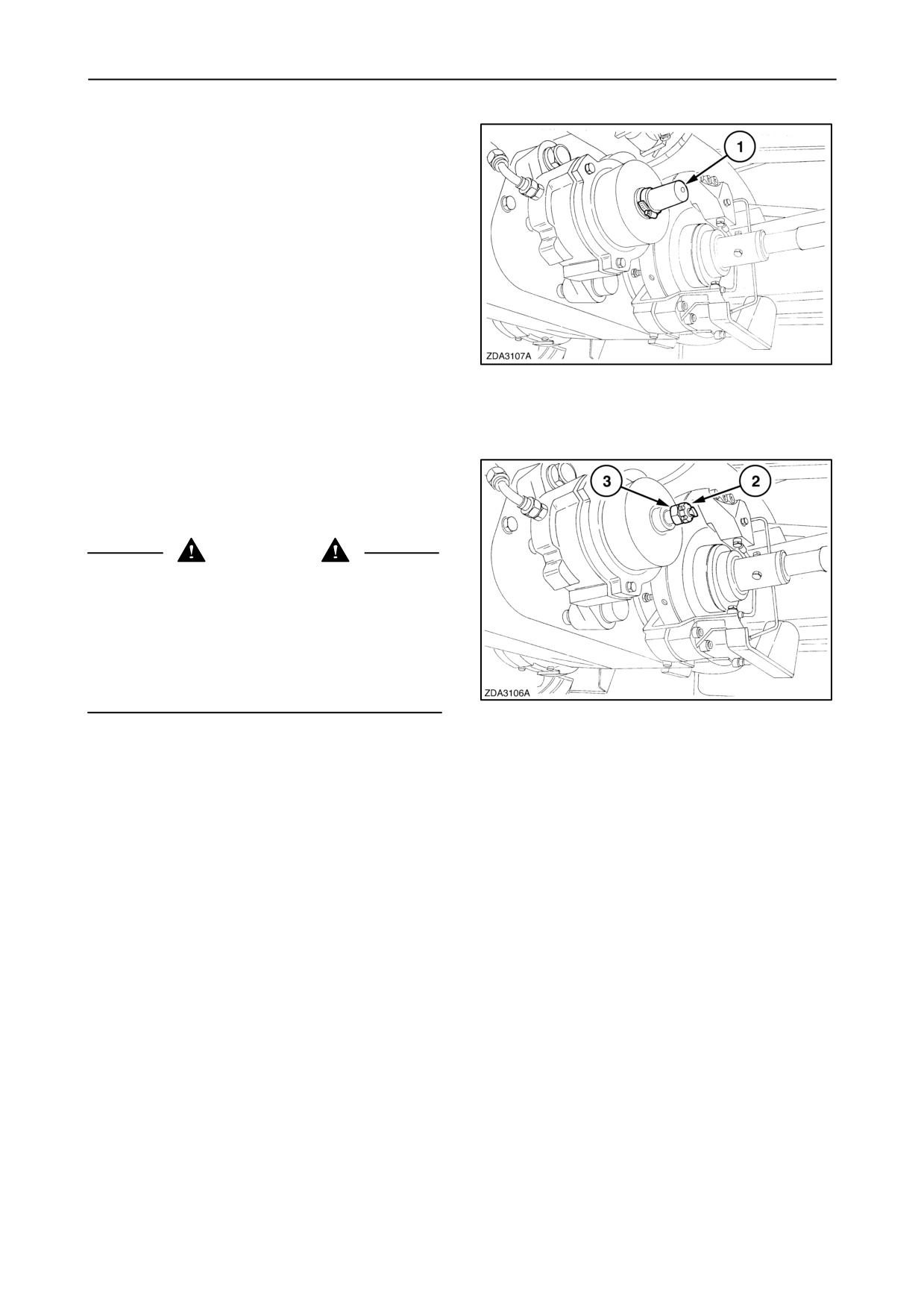
Manual release of the hydraulic parking brake
If it is not possible to release the handbrake
electrically, it can be released manually.
To release the handbrake manually, proceed as
follows:
1. Park the combine level.
2. Raise the header and engage the header safety
latch. Stop the engine.
3. Block the wheels adequately to prevent the
combine from running.
4. Remove rubber cap 1.
1
5. Remove cotter pin 2 and screw on nut 3 until the
handbrake piston is completely pulled backward
to release the pressure on the brake disc.
DANGER
Be aware that the emergency brake does not operate
when the brake is manually disengaged. Repair as
soon as possible to restore correct operation. In the
meantime, use wheel edges to prevent the combine
from running away whenever parked.
2
5-11
SECTION 5 - FAULT FINDING
Gearshifting
If not possible to select gears electronically (gearshift
selector switch from the cab), it can be done
manually, proceeding as follows:
1. Park the combine level (if possible).
2. Raise the header and engage the header safety
latch. Stop the engine.
3. Block the wheels adequately to prevent the
combine from running.
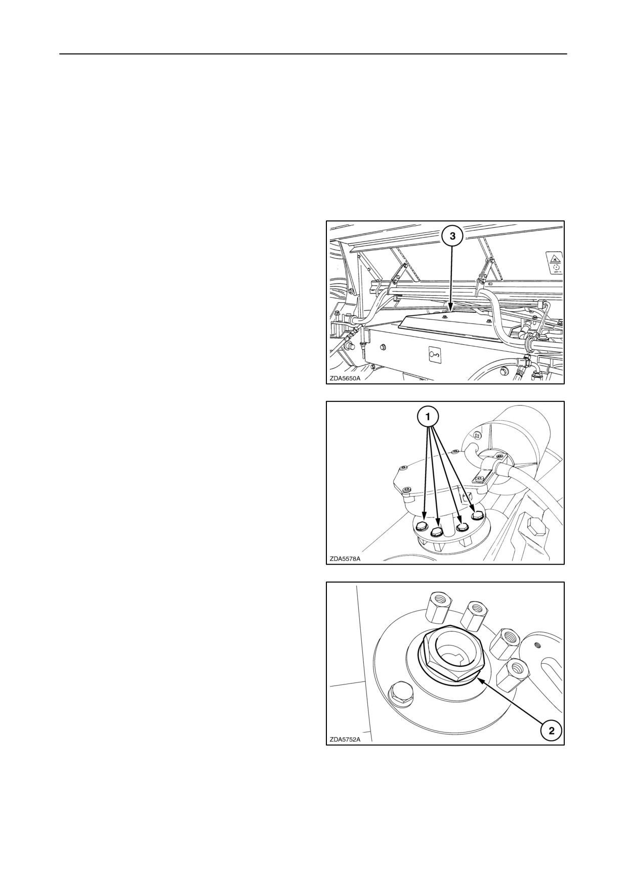
4. Loosen the bolts to remove traction gearbox
cover plate 3.
3
5. Loosen four bolts 1 and remove the electric
motor.
4
6. Use the special tool (located at the left-hand side
of the straw elevator) to turn nut 2 underneath the
electric motor.
5
5-12
SECTION 5 - FAULT FINDING
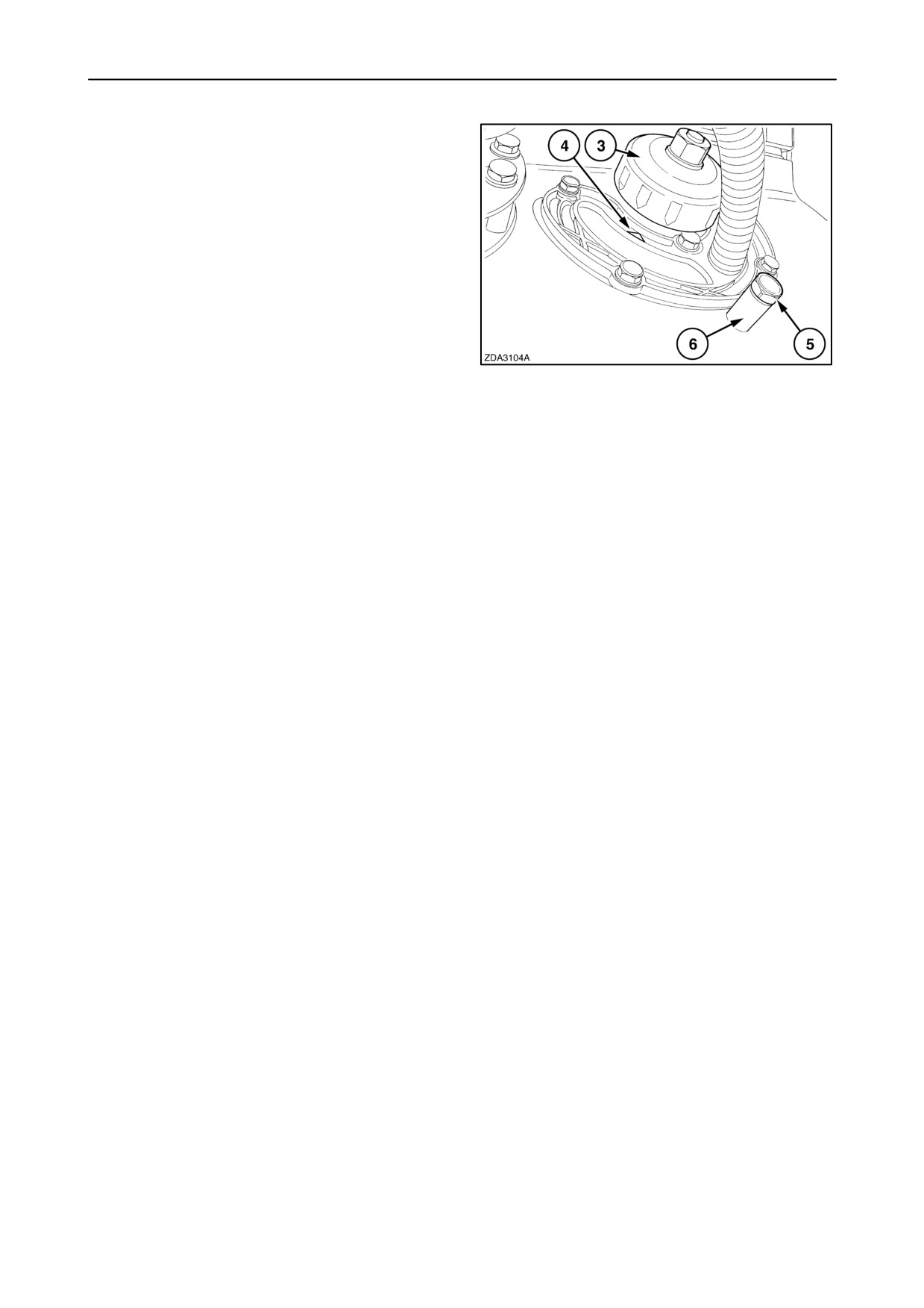
7. To check if a gear is selected, a number of gear
on indicator ring 3 should align with arrow 4 on the
gearshift sensor.
8. To block the manual selected gear, loosen bolt 5
and remove bushing 6.
9. Install bolt 5 (without the bushing), to block the
selected gear (the bolt need to take a hole of the
sheave inside the traction gearbox)
6
NOTE: If the bolt is not easy to turn in the gearbox,
move nut 2 (fig. 5) with the special tool until the bolt
going easy into the gearbox.
5-13
SECTION 5 - FAULT FINDING
HYDRAULIC VALVE ELECTRICS
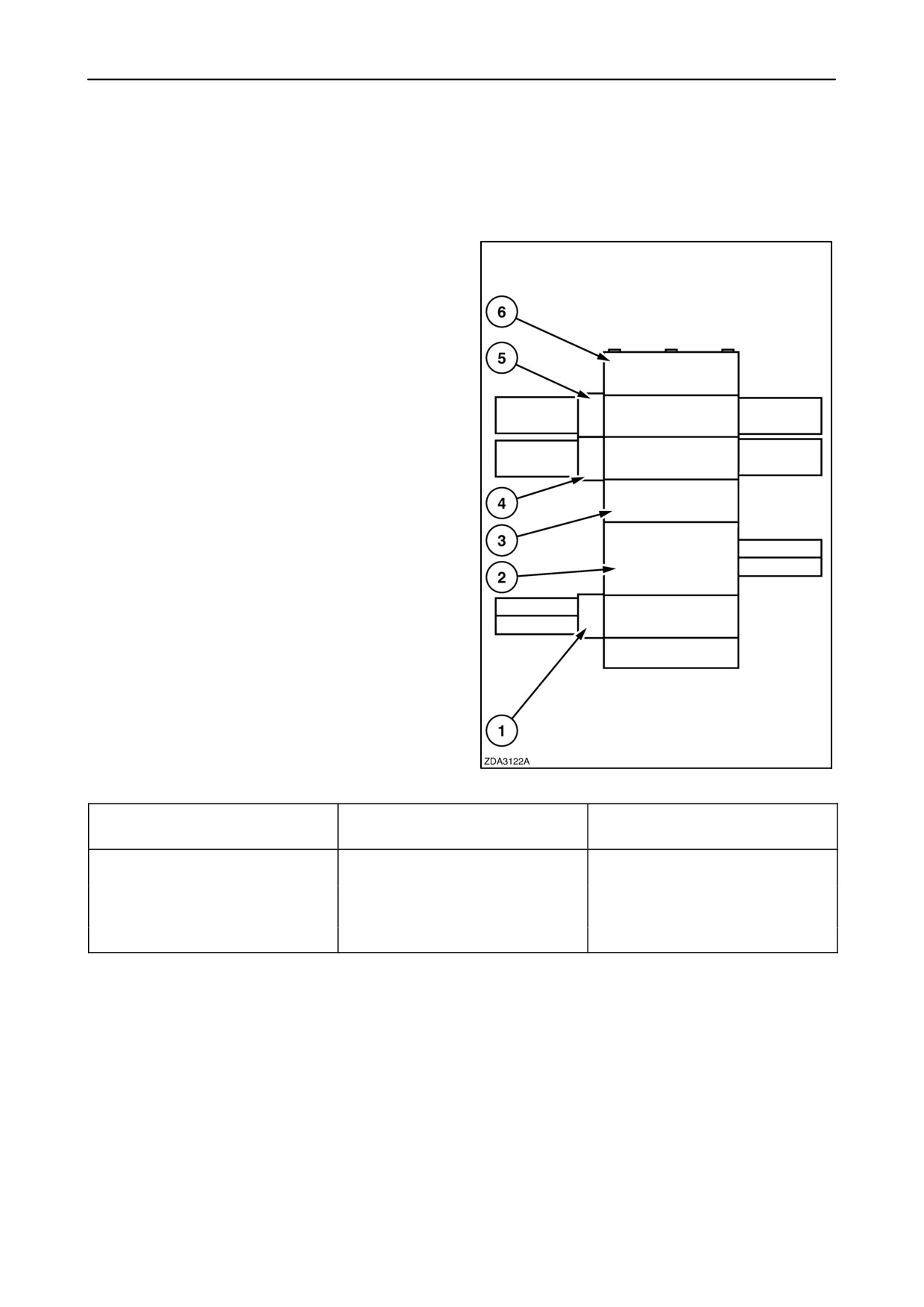
Hydraulic valve located after the left-hand side
behind the steering platform.
1. Header lift
2. Connecting plate with accumulator
3. Priority valve
4. Drum variator
5. Unloading auger swing
6. End plate
7
CONCERN
POSSIBLE CAUSE
CORRECTION
No header height control (1),
No current to spool.
Check fuse and replace, if needed.
No drum variator movement (4),
or no unloading movement
No hydraulic control.
Check oil level and top up, if
control (5)
needed.
Contact your local dealer.
5-14
SECTION 5 - FAULT FINDING
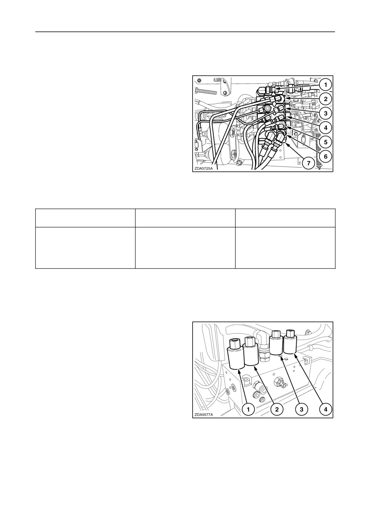
Hydraulic valve located at the left-hand side of the
straw elevator.
1. Connecting plate
2. Reverser
3. Lateral float
4. Reel for/after
5. Reel up/down
6. Reel drive (if installed)
7. End plate
8
CONCERN
POSSIBLE CAUSE
CORRECTION
No reel vertical (5) or horizontal
No current to spool.
Check fuse and replace, if needed.
(4) control, no lateral float (3),
no reversing mechanism (2), or
No hydraulic control.
Check oil level and top up, if
no reel drive (6)
needed.
Contact your local dealer.
Hydraulic low pressure valve located on the engine
gearbox.
1. Main clutch
2. Handbrake
3. Straw elevator clutch
4. Unloading clutch
9
5-15
SECTION 5 - FAULT FINDING
5-16
SECTION 6 - VEHICLE STORAGE
SECTION 6 - VEHICLE STORAGE
Your combine represents an important investment
- Spray under an angle of minimum 25° (do not
and its life depends upon how well you take care of
spray in perpendicular direction).
it.
- Maximum water temperature: 60°C (140°F).
END-OF-SEASON SERVICE
- Maximum water pressure: 60 bar (870 PSI).
Do not use chemicals.
Follow the steps outlined below at the end of each
season’s use or when the machine will not be used for
- Legislation in certain countries and good
an extended period of time. This will ensure the
practice requires special treatment of waste
combine is kept in good condition and ready for the
water through sedimentation and oil
next season.
separation and controlled removal of
residues.
1. Remove the head and the straw elevator to
facilitate cleaning.
3.
Leave covers open at the bottom of the elevators
to allow any moisture to drain out. Leave the
2. Clean the interior and exterior of the combine
unloading auger cleaning doors open.
thoroughly because any chaff and dirt left in the
machine will attract moisture and cause rust.
4.
After cleaning the combine with water, start the
engine and engage the threshing mechanism to
NOTE:
make sure that all water is disappeared out of the
combine.
• Before using pressure washing, clean the
5.
After +/- 15 minutes disengage the threshing and
combine with compressed air.
Clean only when the combine is fully dried.
stop the engine.
6.
Remove the sieves, clean them and coat with oil
• Avoid pressure washing at ambient
or a rust preventative.
temperatures below 105 C (505 F). After cleaning
place the combine in a heated workshop or dry
7.
Remove all chains. Clean and coat the chains
barn for at least 24 hours.
with oil. Reinstall them, then adjust to the correct
tension.
• Avoid to direct water jets onto electric equipment,
bearings, seals, gearbox, oil tank or fuel tank filler
8.
Lubricate the machine thoroughly, as described
caps, into the engine exhaust, engine, cab air
in
“SECTION
4
-
LUBRICATION AND
filters and decals.
MAINTENANCE”.
9.
Coat all bright parts (except the pulley and the
• When using a high pressure washer spray:
variator discs) with paint, a rust preventative, oil
or grease to protect them from rust.
- Keep a minimum distance of 30 cm (11’’)
between the spray gun and the surface to be
10. Retract all hydraulic cylinders and coat exposed
cleaned.
parts of the cylinder rods with grease.
6-1
SECTION 6 - VEHICLE STORAGE
11. Clean all belts, then check belt tension.
23. Switch on the air conditioning while the engine is
Adjust if necessary.
running, only if the ambient temperature is above
15°C
(60°F) minimum. This will ensure
12. Reinstall the straw elevator.
lubrication of the compressor parts. Operate the
air-conditioning system for at least 15 minutes.
13. Clean the air filter element.
24. Reinstall the engine opening seals.
14. Use compressed air, or water under pressure, to
clean out the engine radiator. Use a low-pressure
water jet, or compressed air, to clean the
Periodic checks will help to keep your combine
air-conditioner condenser fins.
maintenance and repairs to a minimum and avoid
costly breakdowns during the season.
15. Check the anti-freeze content in the engine
Therefore, it is good practice to have the
cooling system.
combine inspected at the end of the season. Your
NEW HOLLAND dealer will gladly quote a price
16. Fill the fuel tank completely.
for this work.
17. Store the combine in a dry place, protected from
the weather.
ORDERING PARTS AND/OR
ACCESSORIES
18. Close off all engine openings with plugs or
greaseproof paper.
When preparing the combine for storage, check
19. Support the combine on wooden blocks to relieve
thoroughly for any parts that may have become worn
the weight from the tyres. Leave tyres inflated.
and need replacing.
20. Disconnect the battery cables. Clean and charge
the batteries in situ.
Parts and/or Accessories should be ordered at once
and fitted before the next harvesting season.
IMPORTANT: The batteries should be charged every
8 to 10 weeks with a 5 to 6 amperes current for a
When ordering Parts and/or Accessories, always
period of 24 hours to a minimum of 12.6 volt.
ensure to give your NEW HOLLAND dealer the model
number and serial number of your combine. See the
NOTE: Removing the batteries will not harm the
chapter headed ‘‘Product Identification’’.
storage of information in the InfoViewt monitor.
21. Straw chopper: Remove all knives and bushings,
INSIST ON GENUINE NEW HOLLAND ‘‘QUALITY’’
grease them thoroughly and reinstall them onto
PARTS AS THEY WILL GIVE THE BEST
the rotor.
PERFORMANCE AND ARE COVERED BY OUR
WARRANTY.
22. Every
4 weeks, remove the engine opening
seals, start the engine and run at 3/4 throttle for
1 to 2 hours. Move all the variators from minimum
FOR BEST PERFORMANCE YOUR COMBINE
to maximum, and vice versa, to ensure adequate
SHOULD BE SERVICED BY AN AUTHORISED
lubrication to prevent rust.
NEW HOLLAND DEALER.
6-2
SECTION 6 - VEHICLE STORAGE
PRESEASON SERVICE
7.
Check machine adjustments, as described in
“SECTION
4
-
LUBRICATION AND
MAINTENANCE”.
Follow the steps outlined below at the beginning of
each season to ensure the machine is in good
condition and ready for use.
8.
Remove the engine opening seals. Run the
engine to bring it up to operating temperature,
1.
Remove the wooden blocks supporting the
then drain the rust preventative oil. Replace the
combine.
oil filter(s) and fill with new engine oil.
2.
Check the tyre pressures and wheel nuts torque.
3.
Lubricate the machine, as detailed in the
9.
Run the engine at half speed, engage the
‘‘Lubrication Schedule’’.
threshing mechanism and the head, and check
for problems.
4.
Check all belt and chain tensions (including the
straw elevator and grain elevator chain).
10. Run the engine at full speed and check the speed
5.
Remove the protective oil from the sieves and
on the intermediate shaft with a tachometer.
reinstall them in the machine.
6.
Check the oil level of the following and add oil, if
11. Drive the combine to check the operation of the
needed:
hydraulic equipment and the brakes.
• Traction gearbox
12. Stop the combine and replace the covers of the
• Final drive gearboxes
grain and returns cross auger, the bottom covers
and the cleaning doors of the grain and returns
• Brake fluid reservoir
elevator, and the unloading tube.
• Hydrostatic hydraulic reservoir
13. Lubricate the combine once again, but do not
• Engine gearbox
overgrease.
• Bubble-up gearbox
14. It is recommended to have your NEW HOLLAND
• Unloading drive gearbox
dealer or a refrigerant specialist check the entire
air-conditioning system for leakage at the
• Unloading tube gearbox
beginning of each season.
6-3
SECTION 6 - VEHICLE STORAGE
6-4
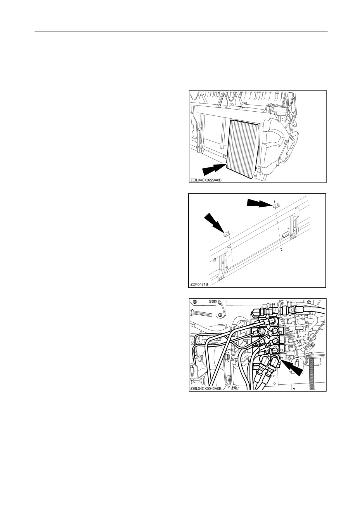
SECTION 7 - ACCESSORIES
SECTION 7 - ACCESSORIES
FEEDING
Side hill weights
This kit can be installed at the rear of the right-hand
side of 15, 17 and 20 ft grain headers when working
on slopes.
1
Crop distribution kit
To improve feeding on 6 straw walker combines, by
moving crop into the centre of the straw elevator.
2
Hydraulic reel rebuild kit
Hydraulic components to allow the operation of
hydraulic reel drive on Extra-Capacity or Varifeedt
grain headers is available.
3
7-1
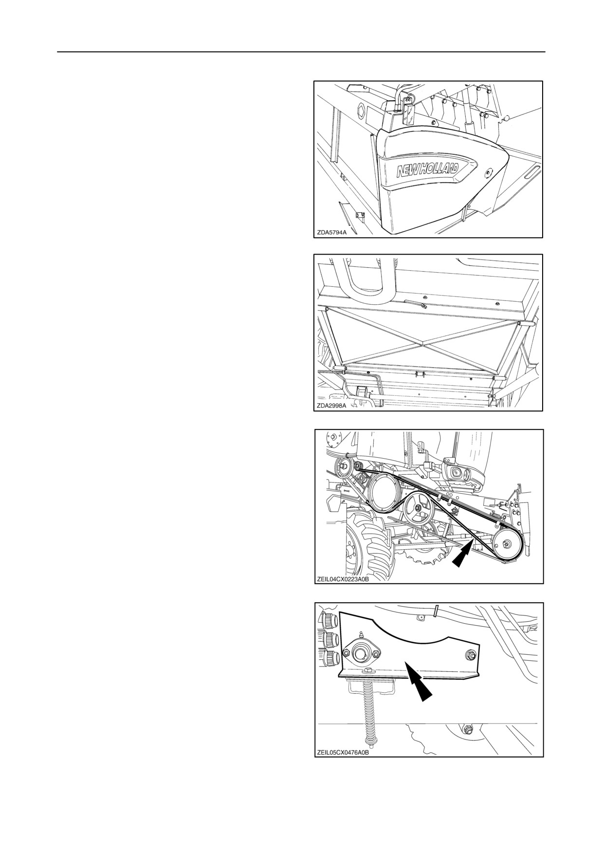
SECTION 7 - ACCESSORIES
Grain header road light kit
For some countries a grain header road light kit is
available.
4
Perforated straw elevator floor section
With this kit, a straw elevator with closed bottom can
be rebuild to a straw elevator with a perforated bottom
door. With the perforated bottom door installed, it is
possible to operate with or without a smooth plate.
The perforated bottom is used to evacuate dirt and
soil when operating in peas, soy, beans, etc.
5
Straw elevator drive
A 4HB straw elevator and header drive belt can be
installed if a maize header or stripper header should
be driven.
6
Intermediate roll
A intermediate roll can be ordered for the models
CX720, CX740, CX760 and CX820.
7
7-2
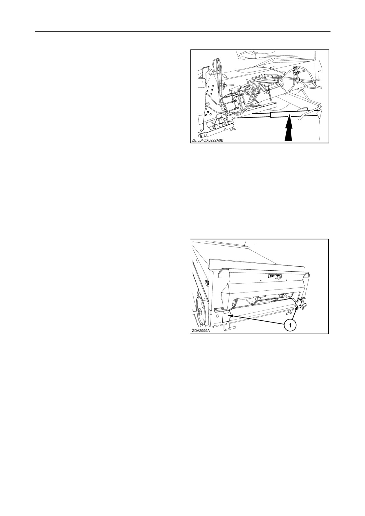
SECTION 7 - ACCESSORIES
Header lift cylinder kit
If working with an 8 row maize header with integrated
stalk chopper, 12 row maize header or 30 ft header
with rape seed extension, it is necessary to install the
cylinder kit.
• diameter 70 mm (2 - 3/4”)
This kit is an accessory for models
CX720, CX740, CX760 and CX820.
• diameter 70 mm (2 - 3/4”) (only Italy)
8
This kit is an accessory for models
CX720, CX740, CX760 and CX820.
• diameter 75 mm (2 - 15/16”)
This kit is an accessory for models
CX780, CX820, CX840, CX860 and CX880.
Narrowing plates
Narrowing plates (1) can be installed to harvest rice
or damp straw conditions.
9
Potentiometer for flex header 19 ft
Includes skid extensions and potentiometers. This
enables the header to be operated, in conjunction
with Autofloatt in small grain crops, in the same way
as a rigid grain header.
7-3
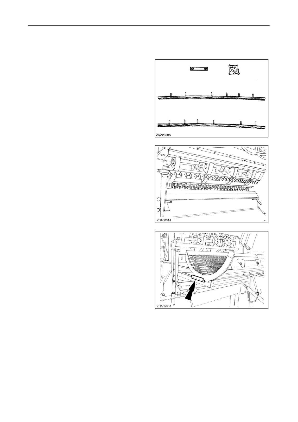
SECTION 7 - ACCESSORIES
THRESHING AND SEPARATION
De-awning slats
Two de-awning slats can be fitted in the front section
of the threshing concave to improve threshing
efficiency in difficult to thresh crops.
10
Rice pins
Rice pins can be installed on a rice concave with a
tooth spacing of 56 mm.
11
Tool to remove the concave
A special tool is available to remove the drum
concave easily.
12
7-4
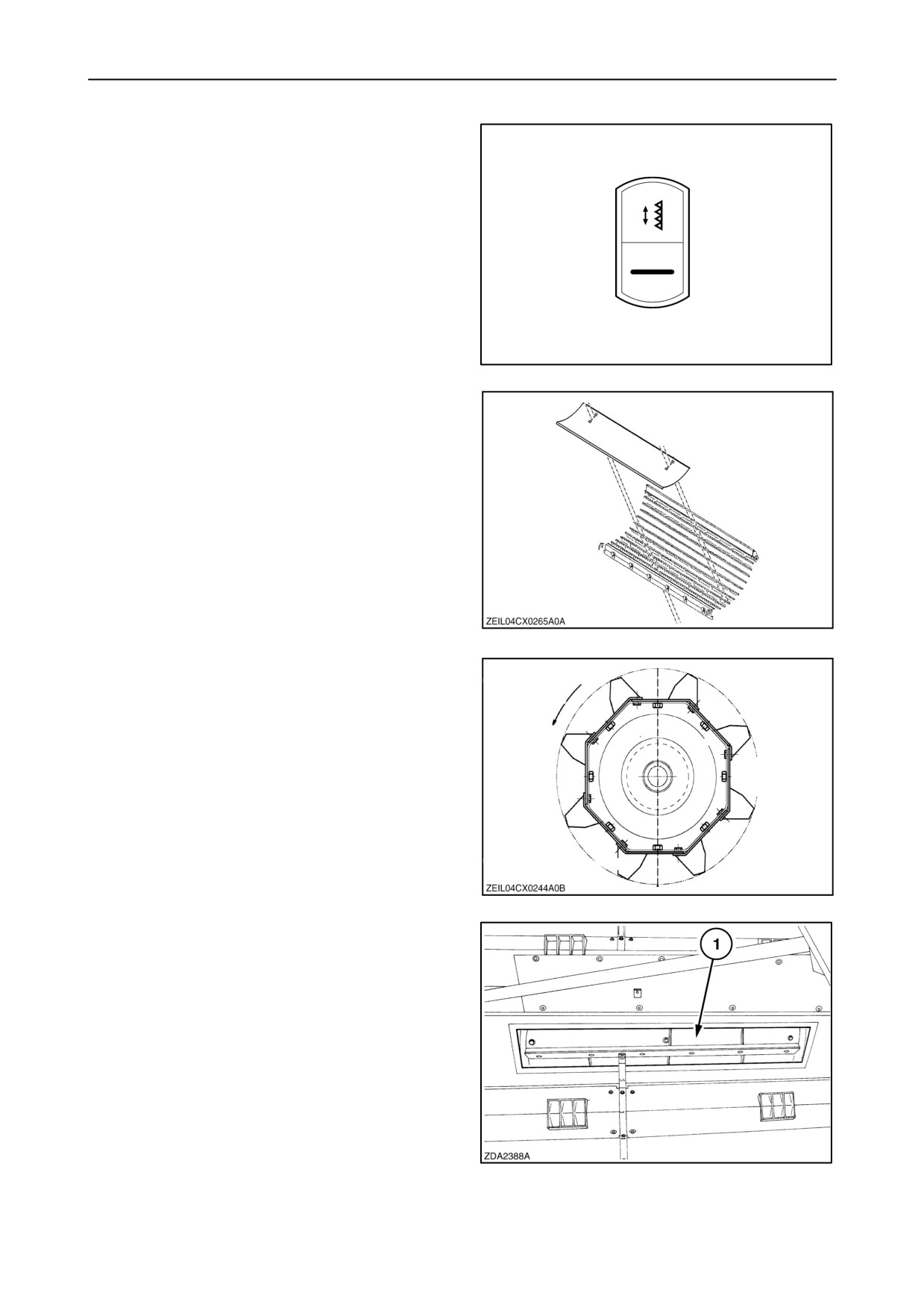
SECTION 7 - ACCESSORIES
Vertical knife electricity kit
A electricity kit with harness and in cab switch is
available to harvest rape seed.
13
Sunflower cover plate
In dry conditions, to reduce load of material on the
cleaning shoe, a plate can be installed in the front of
the drum concave.
14
Beater pins
Toothed bars can be installed instead of the beater
blades for working in difficult, damp or long straw
conditions.
15
Beater blades
Beater blades can be used when working in dry straw
conditions.
Beater wear plates
Wear plates can be added onto the beater blades
when working in abrasive conditions.
16
7-5
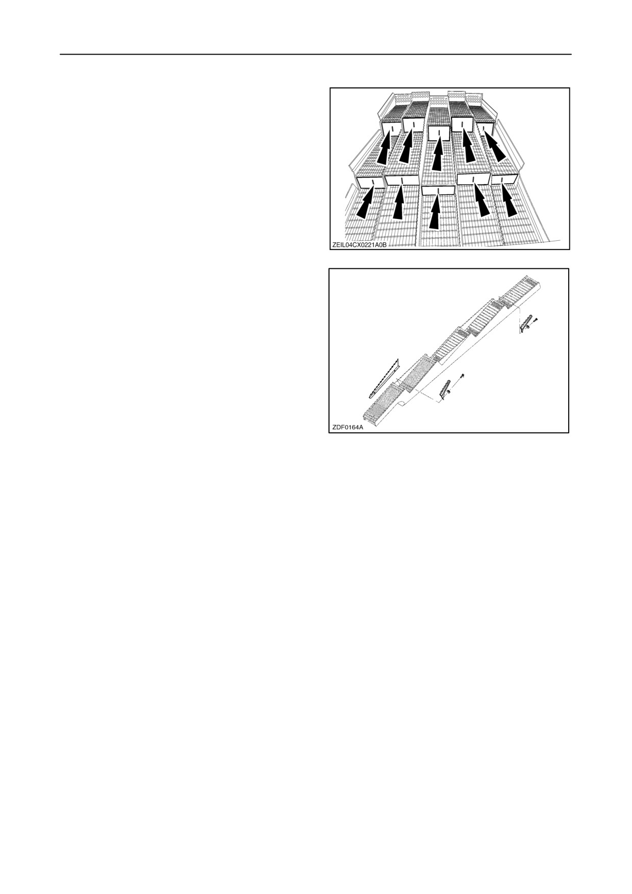
SECTION 7 - ACCESSORIES
Vertical covers on straw walkers
This equipment can be fitted to cover all the vertical
apertures of the straw walkers in order to reduce the
amount of material on the sieves when harvesting
short brittle straw crops.
17
Straw walker raisers
Extra straw walker raisers can be installed when
working in damp straw conditions.
18
Cereals threshing rebuild kit
This equipment can be used to rebuild the combine
from rice version to cereals version.
It consists of:
• Cereals concave
• Standard drum rasp bars for universal drum
7-6
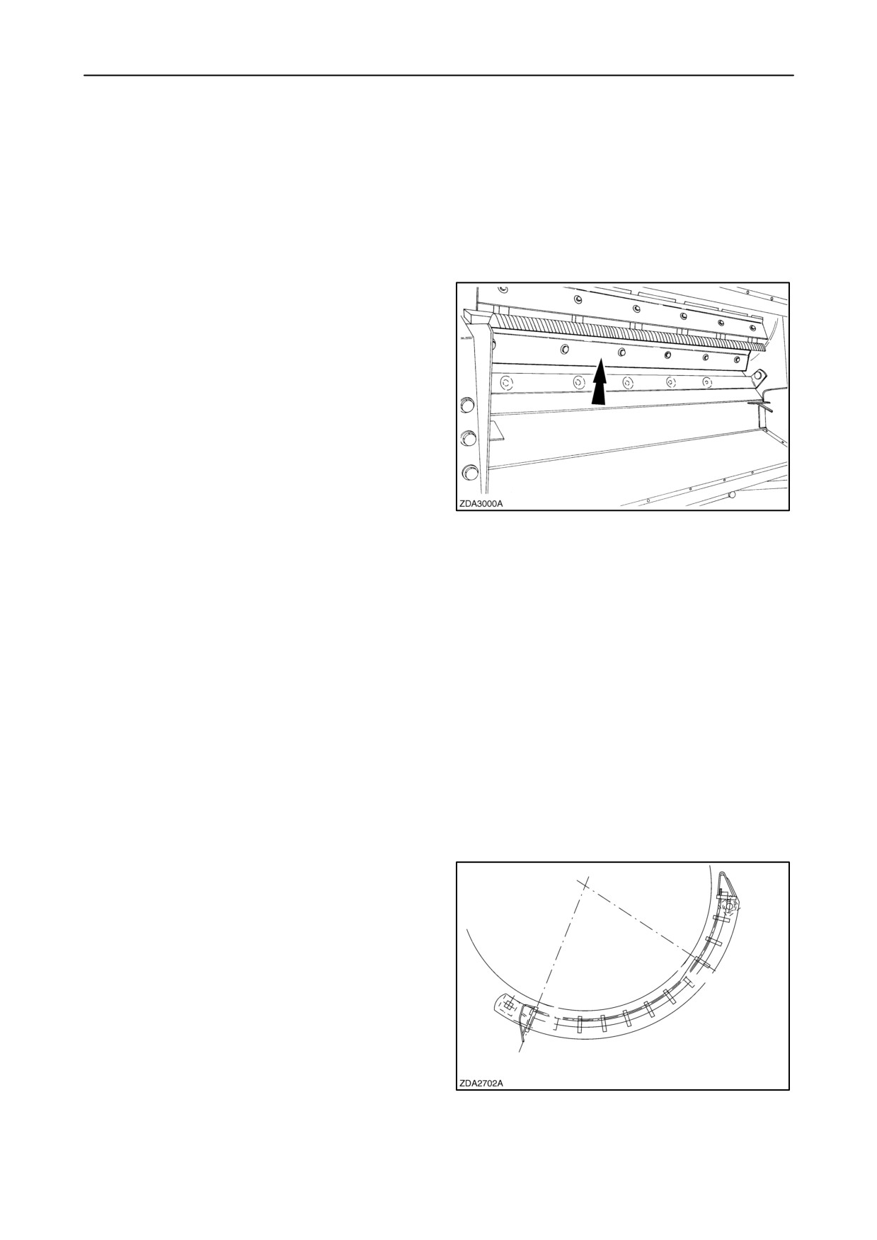
SECTION 7 - ACCESSORIES
Maize threshing rebuild kit
The following equipment to rebuild the combine from
cereals/rice version to maize version is available:
• Maize concave
• Standard rasp bars for universal drum
• Drum cover plates (only with standard drum)
19
• Fan bottom shield (*)
•
4 HB straw elevator and header drive belt
(*) Only needed when rebuilding from cereals version
to maize version.
Rice threshing rebuild kit (if universal drum)
cereals/maize version to rice version is available:
• Peg tooth concave
• Peg bars
• Fan bottom shield (*)
(*) Only needed when rebuilding from cereals version
(with standard drum) to rice version.
Maize concave
A maize concave is available for threshing maize
and/or beans.
20
7-7
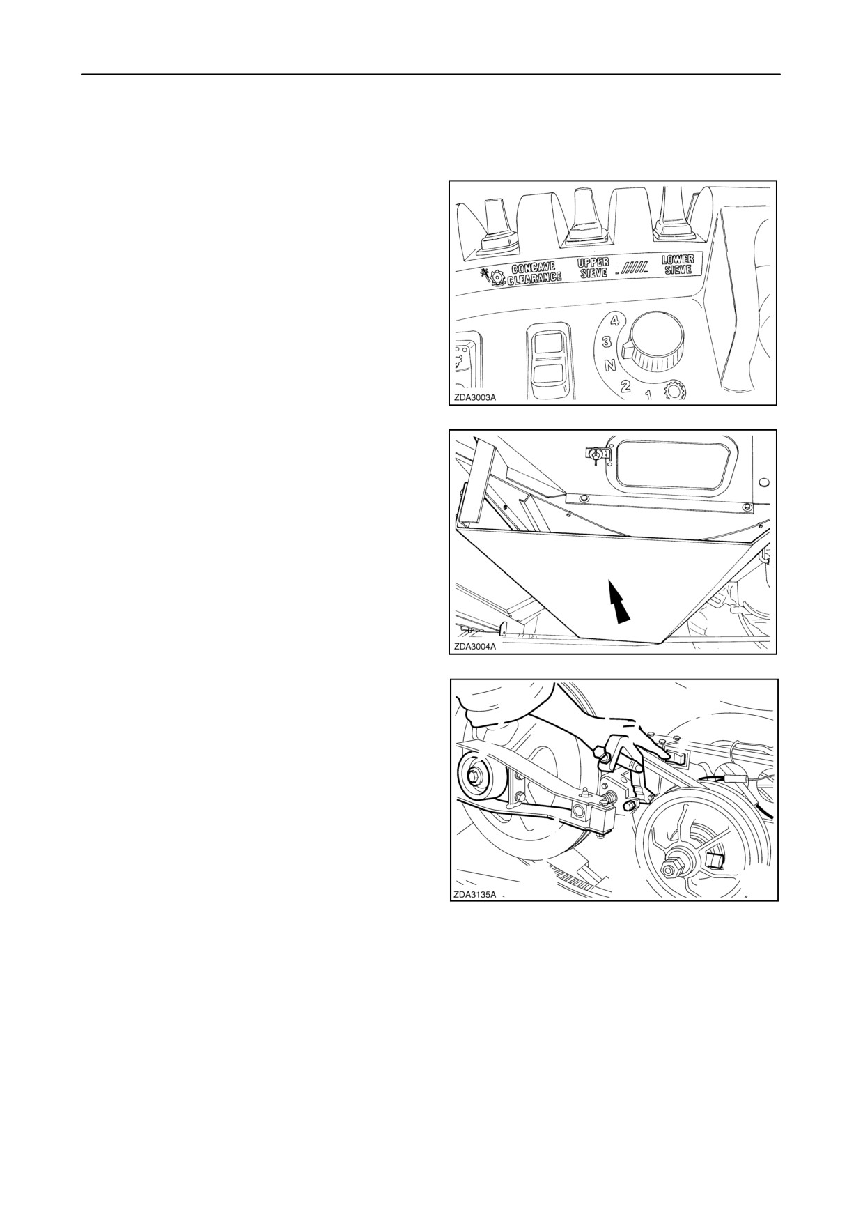
SECTION 7 - ACCESSORIES
CLEANING SYSTEM AND LOWER FRAME
Remote sieve control
This equipment can be installed to adjust the lower
and upper sieve electrically with switches from the
cab and from the inside of the straw hood on the left
side.
21
Fan bottom shield
This guard can be fitted to protect the fan bottom and
shoe levelling box when harvesting maize, sunflower,
soy, beans, rice, etc. or in muddy conditions.
22
Grass seed variator kit
A variator to obtain a lower fan speed adjustment can
be fitted to reduce the wind blow when threshing
small and light seeds (grass seed).
23
7-8
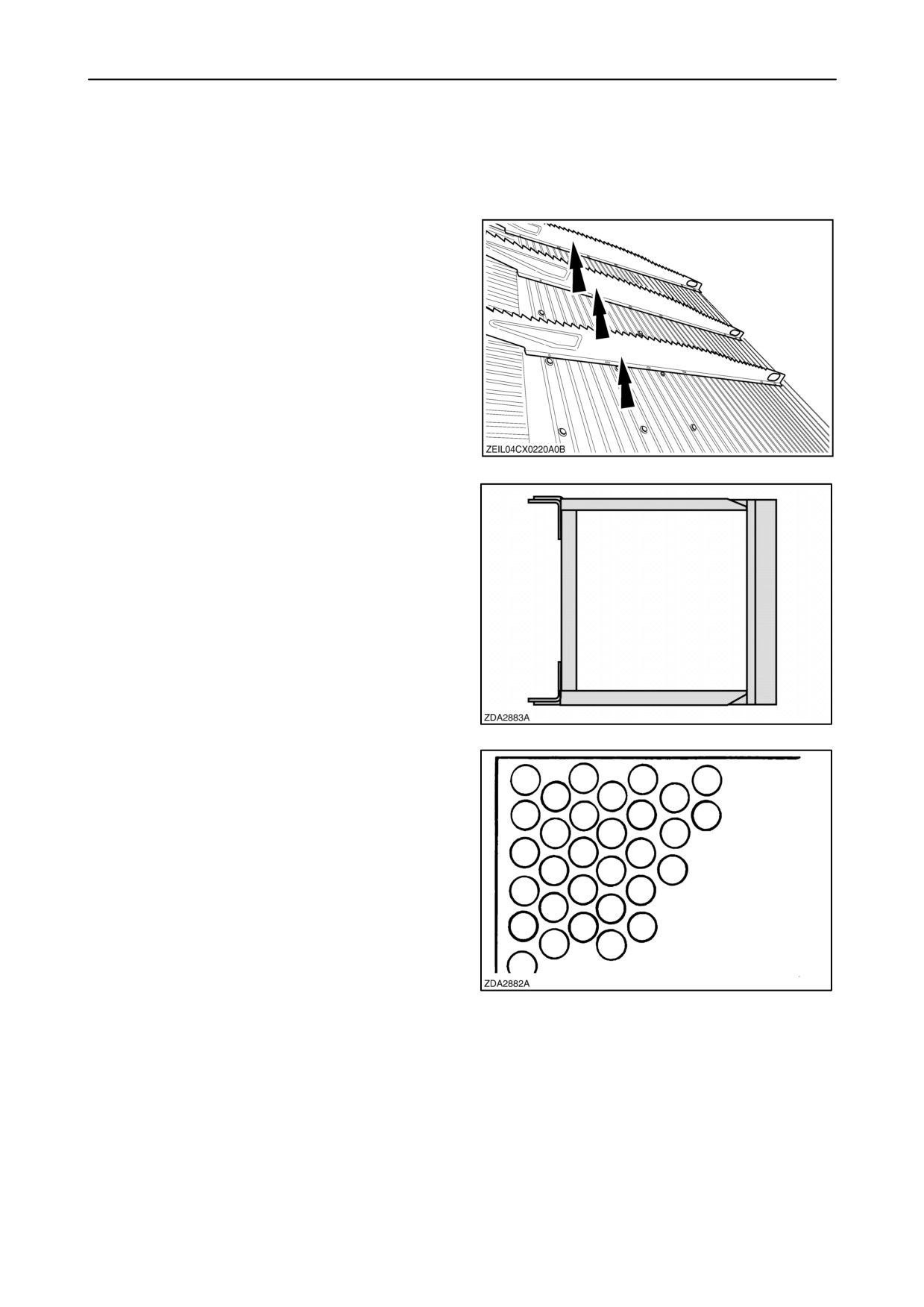
SECTION 7 - ACCESSORIES
Presieve HC 1-5/8”
This sieve can be used when harvesting maize in wet
conditions.
Grain pan divider kit
A grain pan divider kit is available for extreme hilly
conditions. (only for cleaning shoe models without
removable grain pan)
24
Round hole sieve frame
A frame can be obtained to adapt to a round hole
sieve of your preferred hole size.
25
Round hole sieve (16 or 18 mm)
A 16 mm or 18 mm diameter round hole sieve can be
used as an lower sieve in maize when operating in
damp conditions, as this sieve can be easily cleaned.
26
7-9
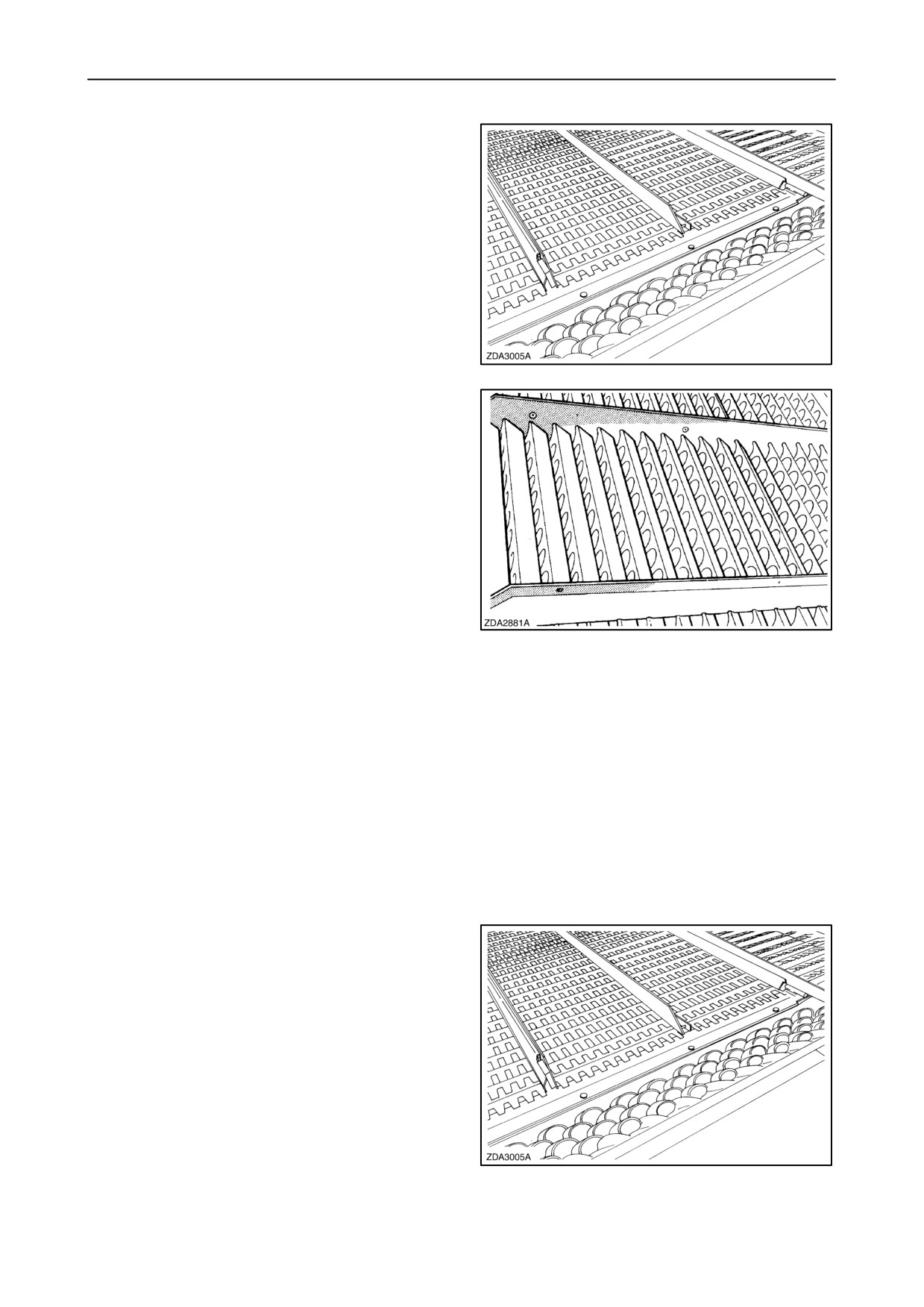
SECTION 7 - ACCESSORIES
Adjustable chaffer 1-5/8” and 1-1/8”
This sieve is recommended as an upper sieve when
harvesting maize.
27
Adjustable upper sieve (Petersen 1-1/8”)
This sieve can be fitted as an upper or lower sieve to
obtain a cleaner sample, especially in oil seed rape.
28
Closz upper sieve
This sieve is available to increase the cleaning
capacity in conditions where excessive amounts of
barley or wheat awns restrict the performance of the
standard 1-1/8” small grain sieve.
Stainless steel curved louver maize upper sieve
This upper sieve with stainless steel curved louvers
is recommended for wet maize conditions.
Graepel sieve extension
This extension can be fitted at the rear of the upper
sieves, in place of the finger rake, to prevent short
straw from passing into the returns auger.
29
7-10
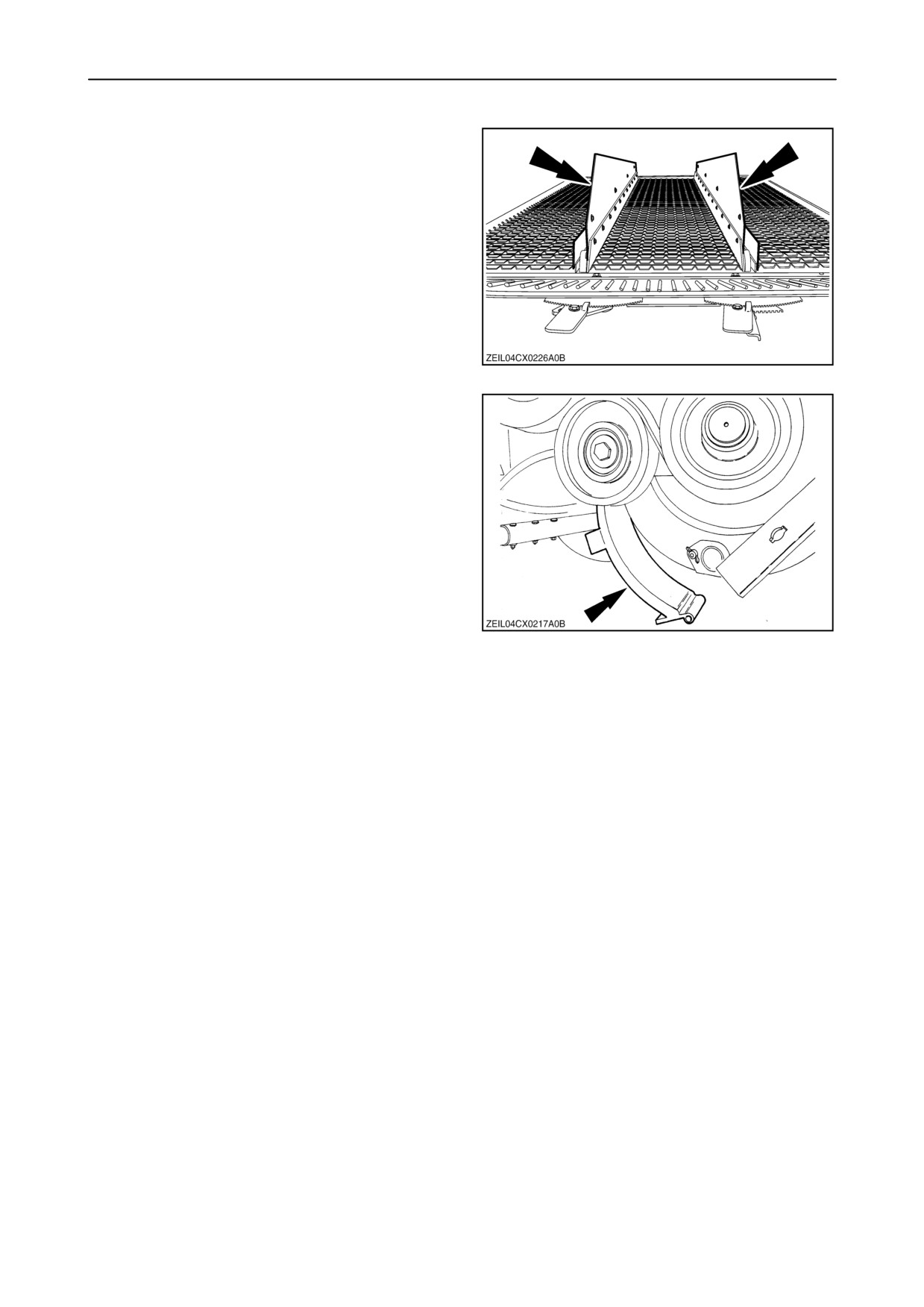
SECTION 7 - ACCESSORIES
Extended sieve dividers
A kit with extended dividers for the pre sieve and
upper sieve is available for extremely hilly conditions.
(only for fixed cleaning shoe models)
30
Smooth rotor thresher covers
When harvesting maize, rape seed and other crops
with large fragile grains
(e.g. beans), smooth
roto-thresher covers should be installed to prevent
grain damage.
31
7-11
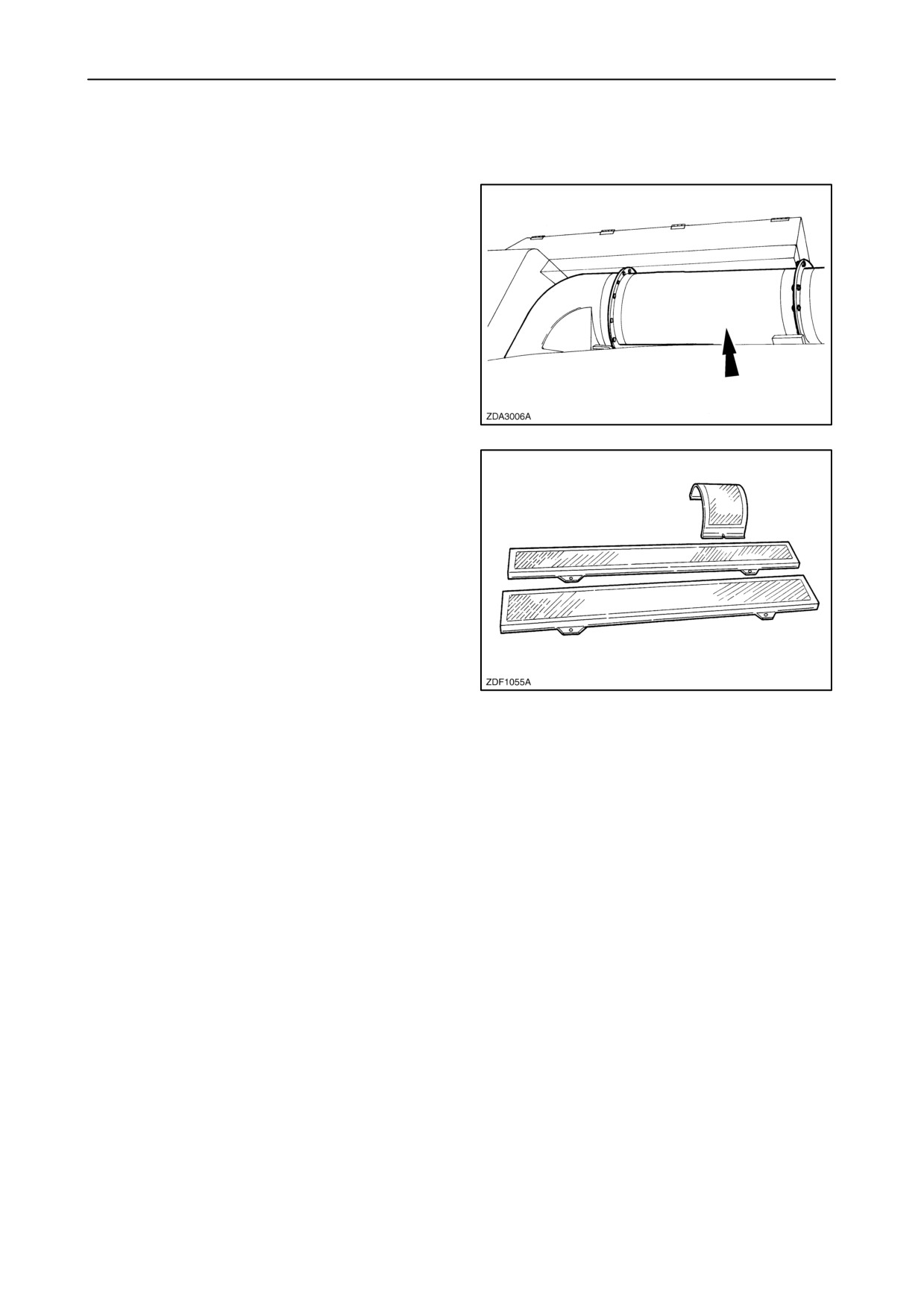
SECTION 7 - ACCESSORIES
CLEAN GRAIN, GRAIN TANK AND UNLOADING
Unloading tube extension kit
An unloading tube extension kit of 0,9 m (3 ft) is
available.
32
Perforated covers: Long or Round
Perforated covers under the clean grain and return
cross auger and the grain elevator can be installed
when threshing beans and peas to obtain a cleaner
grain sample.
33
7-12
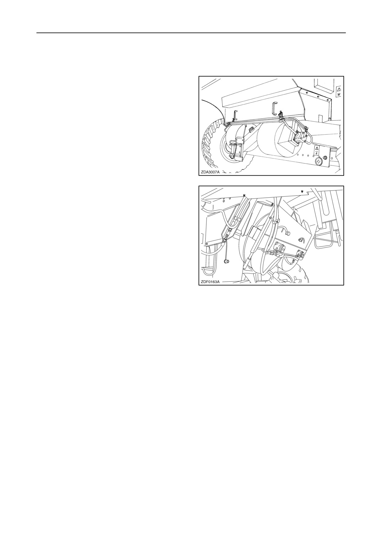
SECTION 7 - ACCESSORIES
STRAW HANDLING
Chaff blower
To avoid a concentrated layer of chaff laying in a
swath behind the combine, a chaff blower can be
installed (in combination with a straw chopper) to
spread the chaff evenly across the full cutting width
of the combine.
34
Chaff spreader
A chaff spreader can be fitted for units without straw
chopper when the chaff from the cleaning shoe is
required to be spread.
35
7-13