New Holland CX720, CX740, CX760, CX780, CX820, CX840, CX860, CX880. Operator's Manual - page 12
SECTION 4 - LUBRICATION AND MAINTENANCE
• The paddle play at the top of the grain
elevator
The functionality of the flow sensor is affected by the
play between the clean grain elevator paddles and
the top of the clean grain elevator. Due to paddle wear
it will be necessary to adjust this distance into the
range of 2 - 3 mm (5/64” - 1/8”).
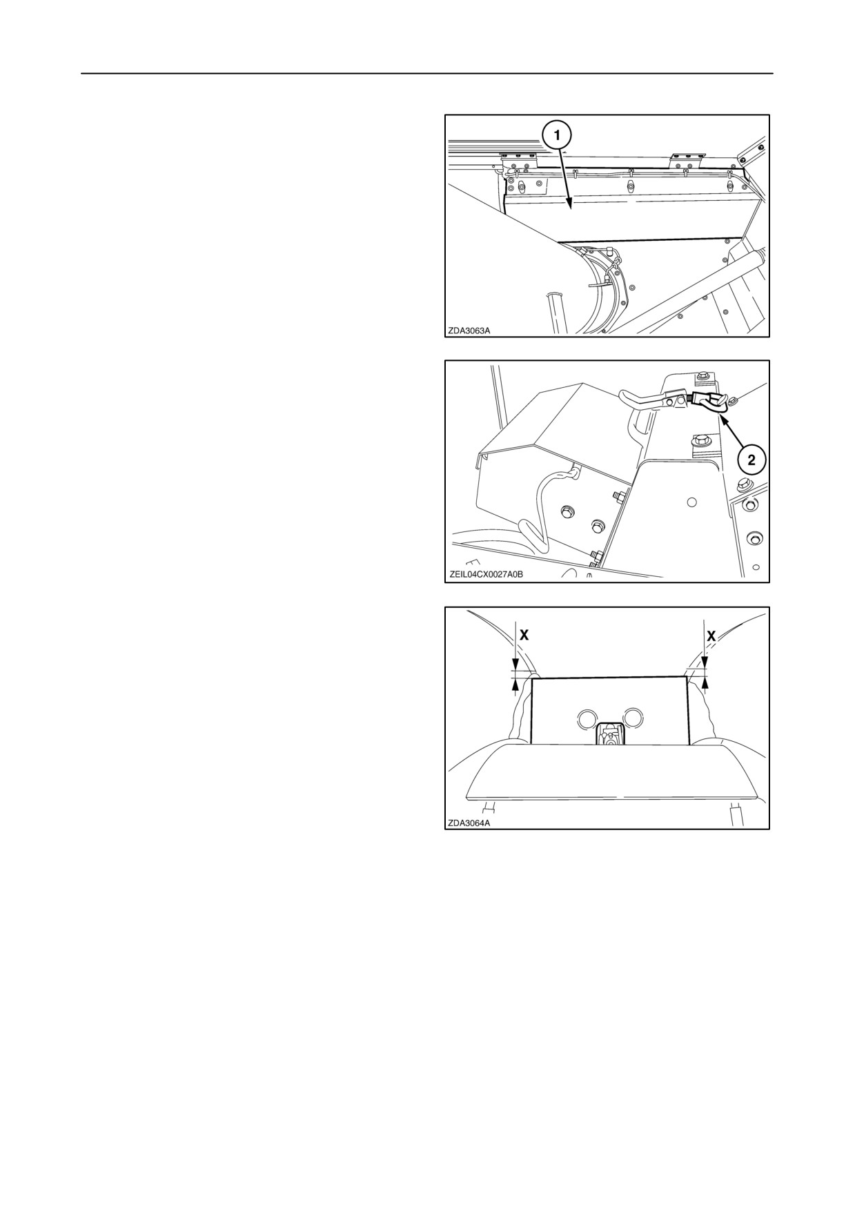
To check paddle tip play, proceed as follows:
1. Open the grain tank covers (if installed)
2. Remove cover 1.
188
3. Open fast coupler 2 on top and swing the sensor
open to the front of the combine.
189
4. Check now distance “X” at position 5 indicated on
the side of the elevator head
(see fig.
187)
between the paddles and top of clean grain
elevator. At the top left and right side of the grain
elevator the distance between paddle tip in its
vertical position with the top edge of the elevator
housing may be not larger than 3 mm (1/8”) but
not smaller than 1 mm (5/128”). Turn the sprocket
by hand to bring the paddle in this position.
IMPORTANT: This job must be checked annually
before the beginning of the season.
5. To adjust paddle tip play. Contact your local
dealer to carry out this job.
190
4-78
SECTION 4 - LUBRICATION AND MAINTENANCE
BRAKES
Fluid change
Foot brakes
The brake fluid has to be changed every two years.
Clean the brakes every 300 hours with compressed
air.
Contact your dealer to carry out this job.
Check the brake linings:
• When the brake warning light illuminates
CAUTION
• In case of leakage or malfunction of the brake
• Every 600 hours in normal conditions
system, immediately contact your New Holland
dealer.
• Every 300 hours in heavy brake conditions (e.g.
”spin turns” in maize, steep hills, ...).
To bleed or to replace the brake linings, contact your
• The seals of the brake slave cylinders contain
local dealer.
fluoroelastomers which, when used under normal
conditions, are perfectly safe.
Parking brake
If however they are exposed to temperatures in
Every 300 operating hours or once a year:
excess of 315° C (599° F), the material will not
burn, but decompose.
• Clean the friction linings with compressed air.
• Check the friction lining wear. The parking brake
linings have to be replaced if the remaining
An extremely corrosive acid is almost impossible
thickness is less than 1 mm (5/128”).
to remove once it has contaminated the skin.
Contact your local dealer to carry out this job.
Every 600 operating hours or once a year a clearance
check and possible adjustment of the parking brake
has to be carried out.
Contact your local dealer to carry out this job.
4-79
SECTION 4 - LUBRICATION AND MAINTENANCE
HYDRAULIC EQUIPMENT
Hydraulic hoses are an important safety element in
modern machinery. However, hose characteristics
alter under pressure, thermal and UV light load over
the years. Therefore, most hoses now have a
production date printed on the metal clamp bushing
which allows to determine the age.
Legislation in certain countries and good practice
require that hydraulic hoses are replaced when they
become 6 years old.
DANGER
Escaping fluid under pressure can penetrate the skin
causing serious injury.
Avoid the hazard by relieving pressure before
disconnecting hydraulic or other lines.
Tighten all connections before applying pressure.
Search for leaks with a piece of cardboard. Protect
hands and body from high pressure fluids.
If an accident occurs, call for a doctor immediately.
Any fluid injected into the skin must be surgically
removed within a few hours. If not, gangrene may
result. Doctors unfamiliar with this type of injury
should refer to a knowledgeable medical source.
IMPORTANT: The hydraulic valves on the right-hand
side can always be operated manually in case of an
electric failure.
Push on the rubber caps of the solenoids to actuate
the hydraulic valve.
4-80
SECTION 4 - LUBRICATION AND MAINTENANCE
TRACKS (IF INSTALLED)
To use the tracks in optimal conditions, proceed as
follows:
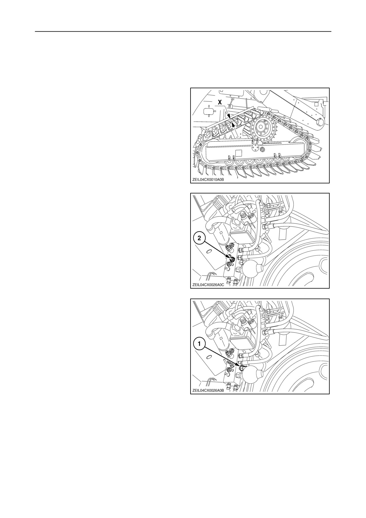
1. Check regulary the hanging down of the chain.
2. Place a straight bar on top at the backside of the
chain as shown.
3. The distance between the bar and the lowest
place of the chain should be between
20 and 35 mm (3/4” and 3/8”).
191
In case of doubt or deviation from the required
tensioning, check and adjust tensioning as follows:
1. If there is no manometer installed, loosen the nut
2 of the valve located under the main valve at the
left-hand side behind the steering platform.
2. Turn the Allen screw counter-clockwise a few
turns to release the pressure.
192
3. Connect a manometer at 1 (1/4”).
4. Close the Allen screw again (clockwise) and
tighten the nut 2 (fig. 192).
5. Activate the unloading tube “swing in” rocker
button while driving a few times forward and
reverse with the combine:
The pressure on the manometer should be read
between 45 and 55 bar (653 and 798 psi).
193
4-81
SECTION 4 - LUBRICATION AND MAINTENANCE
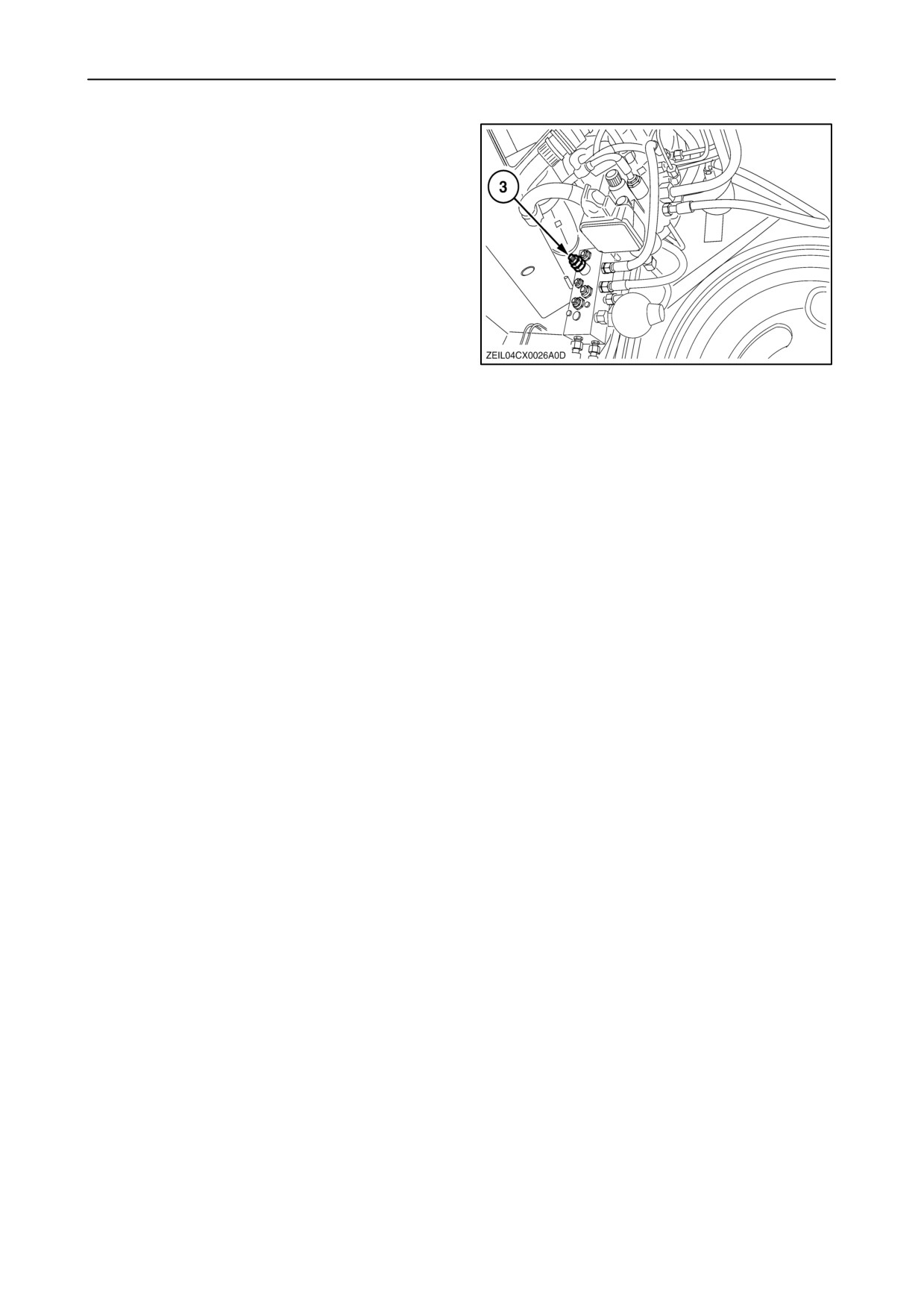
6. If not ok, loosen the nut 3.
7. Turn the Allen screw a quarter by quarter and
repeat the procedure until the pressure is
obtained (45 to 55 bar).
Clockwise to increase the pressure
Counter-clockwise to decrease the pressure
8. After adjusting, tigthen the nut 3.
194
NOTE: To remove the manometer from the valve,
release again the pressure at 2 (fig. 192). Afterwards
activate the unloading tube “swing in” rocker button
while driving a few times forward and reverse with the
combine.
4-82
SECTION 4 - LUBRICATION AND MAINTENANCE
STEERING AXLE
There are three types of steering axles:
• Fixed steering axle
• Heavy Duty Adjustable Steering Axle
(H.D.A.S.A.)
• Power Rear Axle (P.R.A.)
To get a good adjustment of the steering axle, carry
out the following adjustments in these sequence.
1. Steering axle position
2. Axial position of the steering axle
(only H.D.A.S.A. and P.R.A.)
3. Height position (only H.D.A.S.A. and P.R.A.)
4. Track width position (only H.D.A.S.A. and P.R.A.)
5. Toe-in adjustment
6. Steering cylinder adjustment
4-83
SECTION 4 - LUBRICATION AND MAINTENANCE
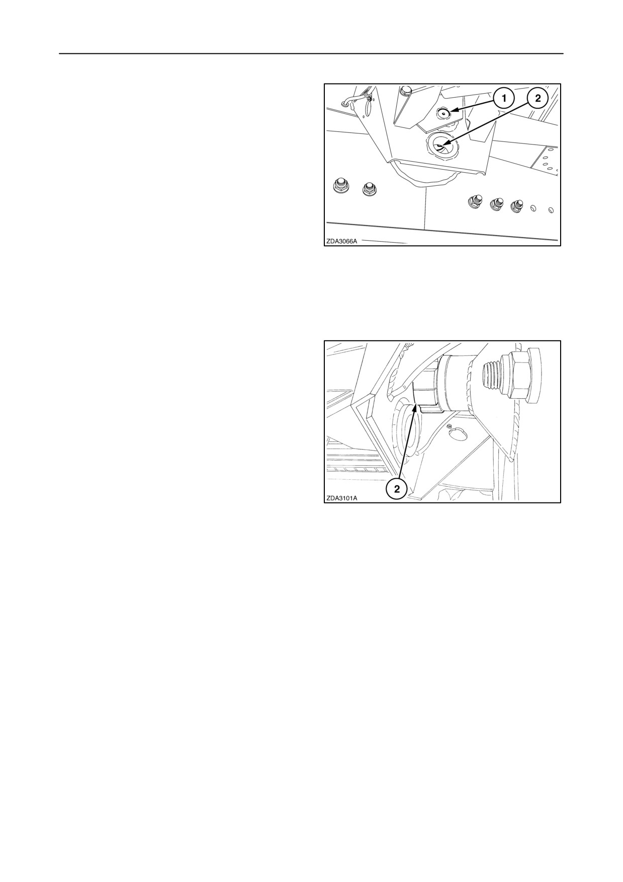
1. Steering axle position
The steering axle should always be installed in the
upper hole 1 in the frame, except when working on
tracks.
When operating on tracks (and rice steering wheels),
the steering axle should be fitted in the lower hole 2
in the frame.
We recommend this job to be carried out by your
New Holland dealer.
195
2. Axial position of the steering axle
The complete steering axle must be axial
repositioned to the frame, depending on the size of
the steering wheels.
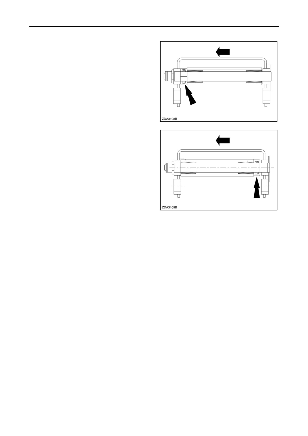
When bushing 2 is fitted at the rear of the steering
axle, then the steering axle is in the front (F) position.
If the bushing is at the front, then the steering axle is
in the rear (R) position.
Figure 197 shows the rear position, figure 198 the
front position.
196
We recommend this job to be carried out by your
New Holland dealer.
4-84
SECTION 4 - LUBRICATION AND MAINTENANCE
Steering axle in the rear (R) position.
(arrow= drive direction)
197
Steering axle in the front (F) position.
(arrow= drive direction)
198
4-85
SECTION 4 - LUBRICATION AND MAINTENANCE
3. Steering axle height position
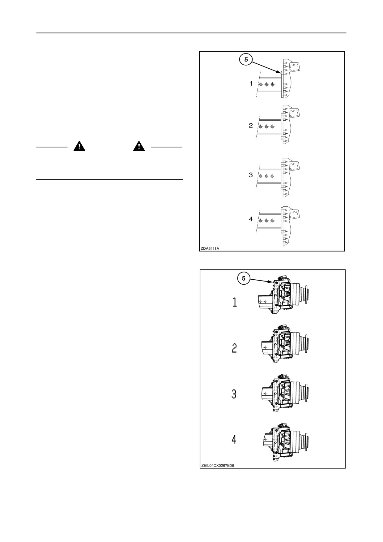
The complete steering wheel (H.D.A.S.A. or P.R.A.)
can be repositioned on the steering axle in order to lift
the machine rear end to a level combine position.
Figures 199 (H.D.A.S.A.) and 200 (P.R.A.) shows
the four different positions.
The height positions are indicated on the steering
wheel hubs on both sides.
CAUTION
Wheel drive assemblies are heavy. Use a lifting
device of adequate capacity. Reposition one side at
a time
H.D.A.S.A.
199
The bolts 5 should be tightened between
780 and 800 Nm (575 and 590 ft.lbs.)
P.R.A.
200
4-86
SECTION 4 - LUBRICATION AND MAINTENANCE
4. Track width position
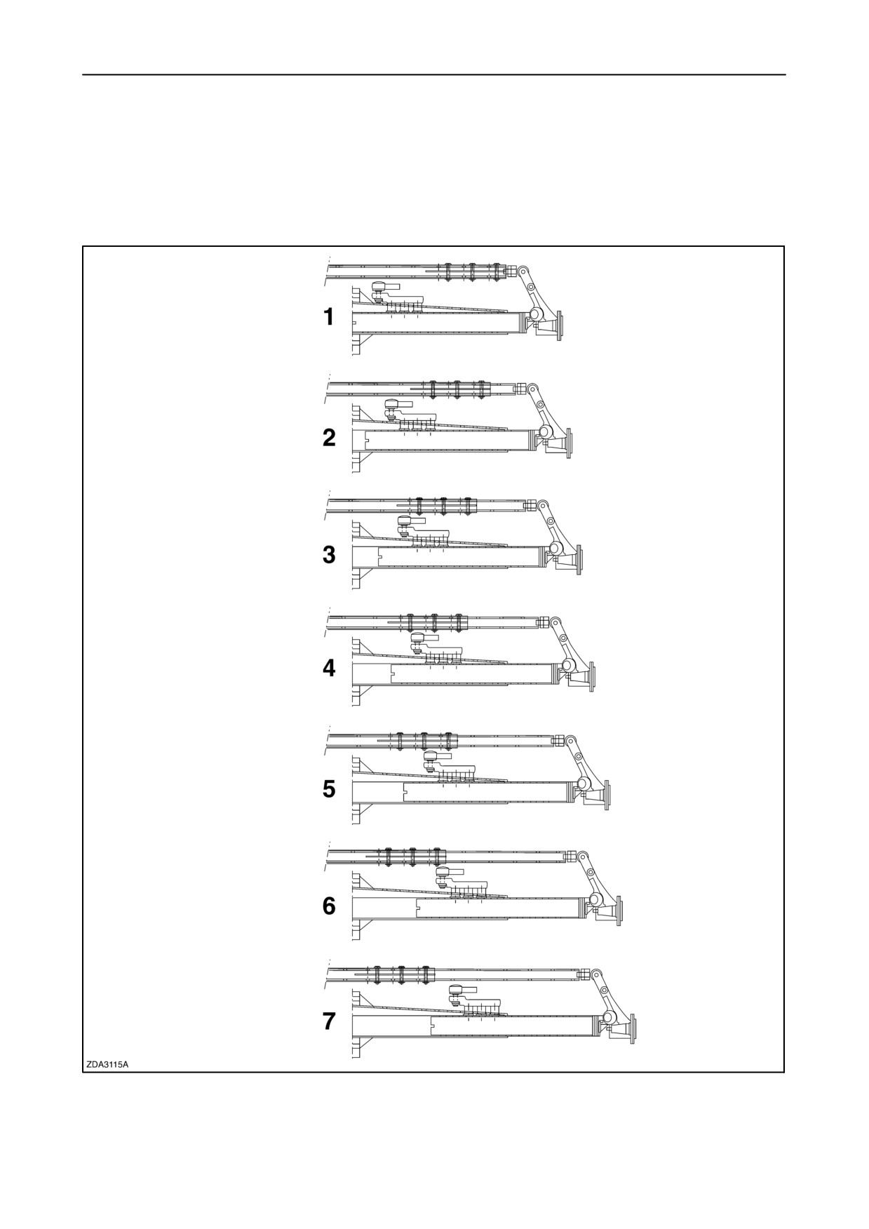
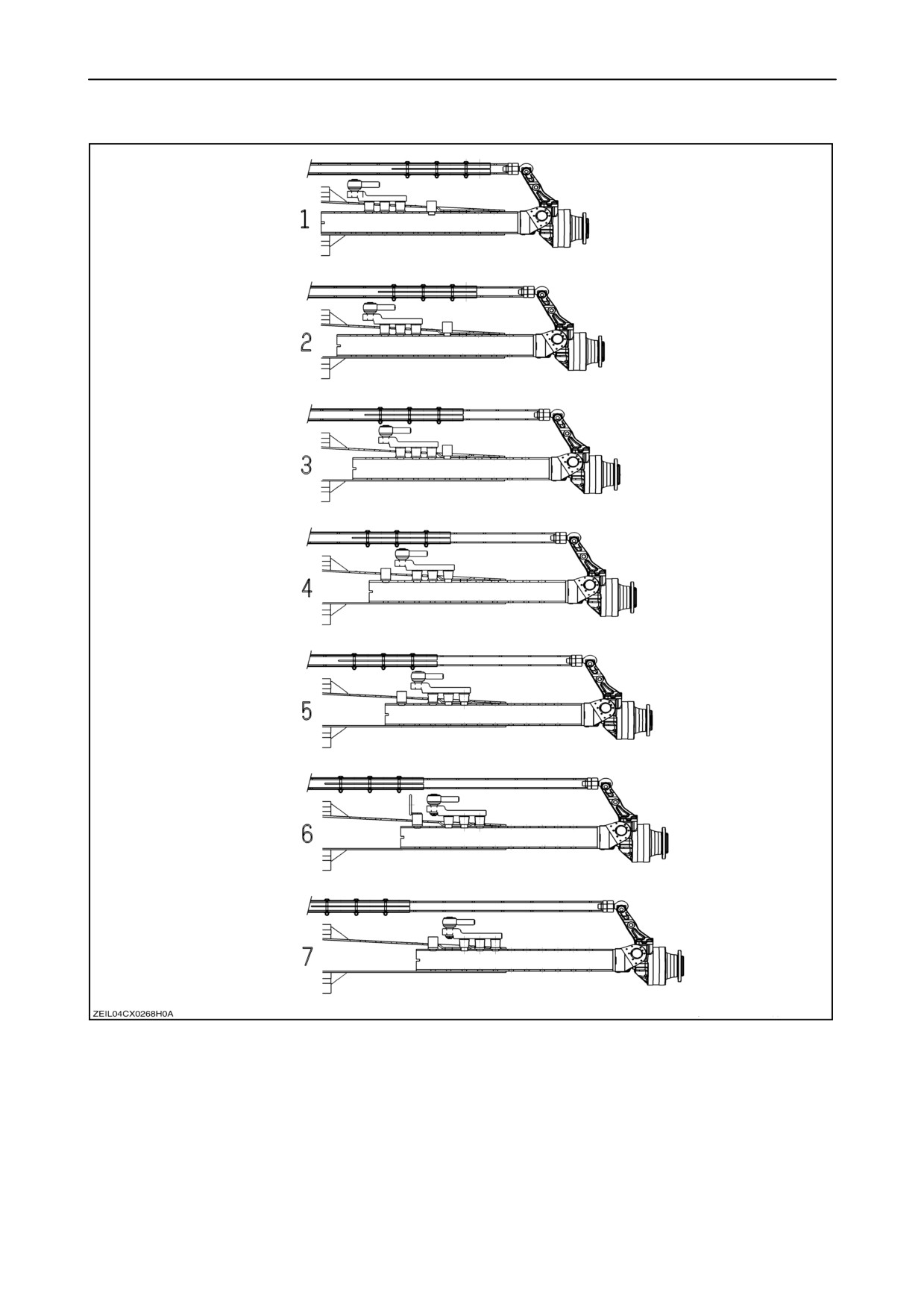
The steering axle has seven track width positions
(H.D.A.S.A. or P.R.A.).
To adjust the track with position, proceed as follows:
1. Apply the parking brake and support the steering
axle so that the steering wheels are clear of the
ground.
CAUTION
Use suitable jack stands, securely positioned
underneath the rear of the machine, before adjusting
the steering axle.
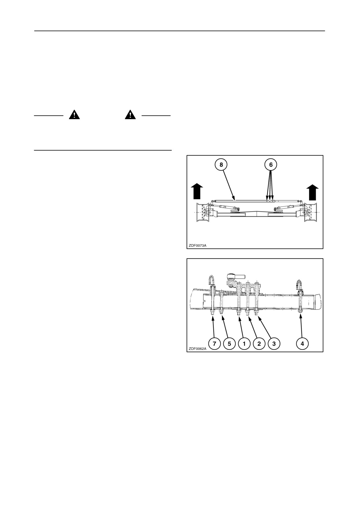
2. Remove the three bolts 6 of the steering rod 8.
201
3. Remove the bolts (1), (2), (3), (4), (5) and (7).
4. Adjust the steering axle to the required width.
In the tables below you can find the different
combinations.
5. After adjusting, install and tighten the bolts (1),
(2), (3), (4), (5) and (7) with a torque between
440 and 460 Nm. (325 and 339 ft.lbs)
IMPORTANT: Check that all the bolts are installed in
the right direction as shown.
202
6. Before install the three bolts 6 in the steering rod
8 (fig. 201), adjust the toe-in, refer to the next step
headed: “5.Toe-in adjustment”
4-87
SECTION 4 - LUBRICATION AND MAINTENANCE
In the following tables you can find the different
tyre combinations and the road speed limitations
(depend the header weight).
Track width position H.D.A.S.A.
203
4-88
SECTION 4 - LUBRICATION AND MAINTENANCE
CX720-740-760: TRACK WIDTH POSITION: H.D.A.S.A. (Europe)
ASSEMBLY POSITION OF STEERING ARM ASSY AND MINIMUM TRACK WIDTH POSITION
STEERING TYRE
Axial position of
F
F
F
F
R
R
F
R
R
the steering axle
Height position
detail nr.
Minimum track
width position
4
620/75R34-170A8-DT820
1
4
4
3
650/75R32-172A8-DT822
1
1
1
4
4
710/75R34-178A8-Megaxbib
1
1
4
3
2
2
1
800/65R32-172A8-DT822
1
1
2
2
4
4
3
2
2
2
900/60R32-176A8-DT830
1
2
2
3
3
3
2
3
2
2
1050/50R32-178A8-MegaXbi
2
2
2
3
4
4
4
4
3
TRACKS INTERTRACTOR
2
2
4
4
“R” : Rear position of the steering axle
“F” : Front position of the steering axle
4-89
SECTION 4 - LUBRICATION AND MAINTENANCE
CX780: TRACK WIDTH POSITION: H.D.A.S.A. (Europe+Not Europe)
ASSEMBLY POSITION OF STEERING ARM ASSY AND MINIMUM TRACK WIDTH POSITION
STEERING TYRE
Axial position of
F
F
F
F
R
R
F
R
R
the steering axle
Height position
detail nr.
Minimum track
width position
4
620/75R34-170A8-DT820
1
4
4
3
650/75R32-172A8-DT822
1
1
1
4
4
710/75R34-178A8-Megaxbib
1
1
4
3
2
2
1
800/65R32-172A8-DT822
1
1
2
2
4
4
3
2
2
2
900/60R32-176A8-DT830
1
2
2
3
3
3
2
3
2
2
1050/50R32-178A8-MegaXbi
2
2
2
3
4
3
3
3
2
900/65R32-172A8-TD8
2
2
3
3
4
4
4
3
TRACKS INTERTRACTOR
2
2
4
4
“R” : Rear position of the steering axle
“F” : Front position of the steering axle
4-90
SECTION 4 - LUBRICATION AND MAINTENANCE
CX820-840-860-880: TRACK WIDTH POSITION: H.D.A.S.A. (Europe)
ASSEMBLY POSITION OF STEERING ARM ASSY AND MINIMUM TRACK WIDTH POSITION
STEERING TYRE
Axial position of
F
F
F
F
R
R
F
R
R
the steering axle
Height position
detail nr.
Minimum track
width position
4
620/75R34-170A8-DT820
3
4
4
3
650/75R32-172A8-DT822
3
3
3
4
4
710/75R34-178A8-Megaxbib
3
3
4
3
2
2
1
800/65R32-172A8-DT822
3
3
4
4
6
4
3
2
2
2
900/60R32-176A8-DT830
3
4
4
5
5
3
2
3
2
2
1050/50R32-178A8-MegaXbi
4
4
4
5
6
4
4
4
3
TRACKS INTERTRACTOR
4
4
6
6
“R” : Rear position of the steering axle
“F” : Front position of the steering axle
4-91
SECTION 4 - LUBRICATION AND MAINTENANCE
CX860-880: TRACK WIDTH POSITION: H.D.A.S.A. (Not Europe)
ASSEMBLY POSITION OF STEERING ARM ASSY AND MINIMUM TRACK WIDTH POSITION
STEERING TYRE
Axial position of
F
F
F
R
R
F
R
R
the steering axle
Height position
detail nr.
Minimum track
width position
4
3
2
2
2
1
650/75R32-172A8-DT822
3
3
4
4
5
6
4
3
2
2
2
1
1
800/65R32-172A8-DT822
3
3
4
4
5
6
6
4
2
3
3
2
2
900/60R32-176A8-DT830
3
4
4
5
5
6
3
2
2
900/65R32-172A8-TD8
5
5
6
3
3
3
2
2
1050/50R32-178A8-MegaXbi
4
4
5
5
6
2
2
2
1
1
1
18.4R42-153A8-RAT23
4
4
5
6
6
7
(duals)
3
3
3
2
2
2
20.8R42-155A8-RAT23
(duals)
4
4
4
5
6
7
2
3
2
2
1
1
420/80R46-159A8-RAT23
(duals)
4
4
5
6
6
7
“R” : Rear position of the steering axle
“F” : Front position of the steering axle
(Only with offset out : bolded)
4-92
SECTION 4 - LUBRICATION AND MAINTENANCE
Track width position P.R.A.
204
4-93
SECTION 4 - LUBRICATION AND MAINTENANCE
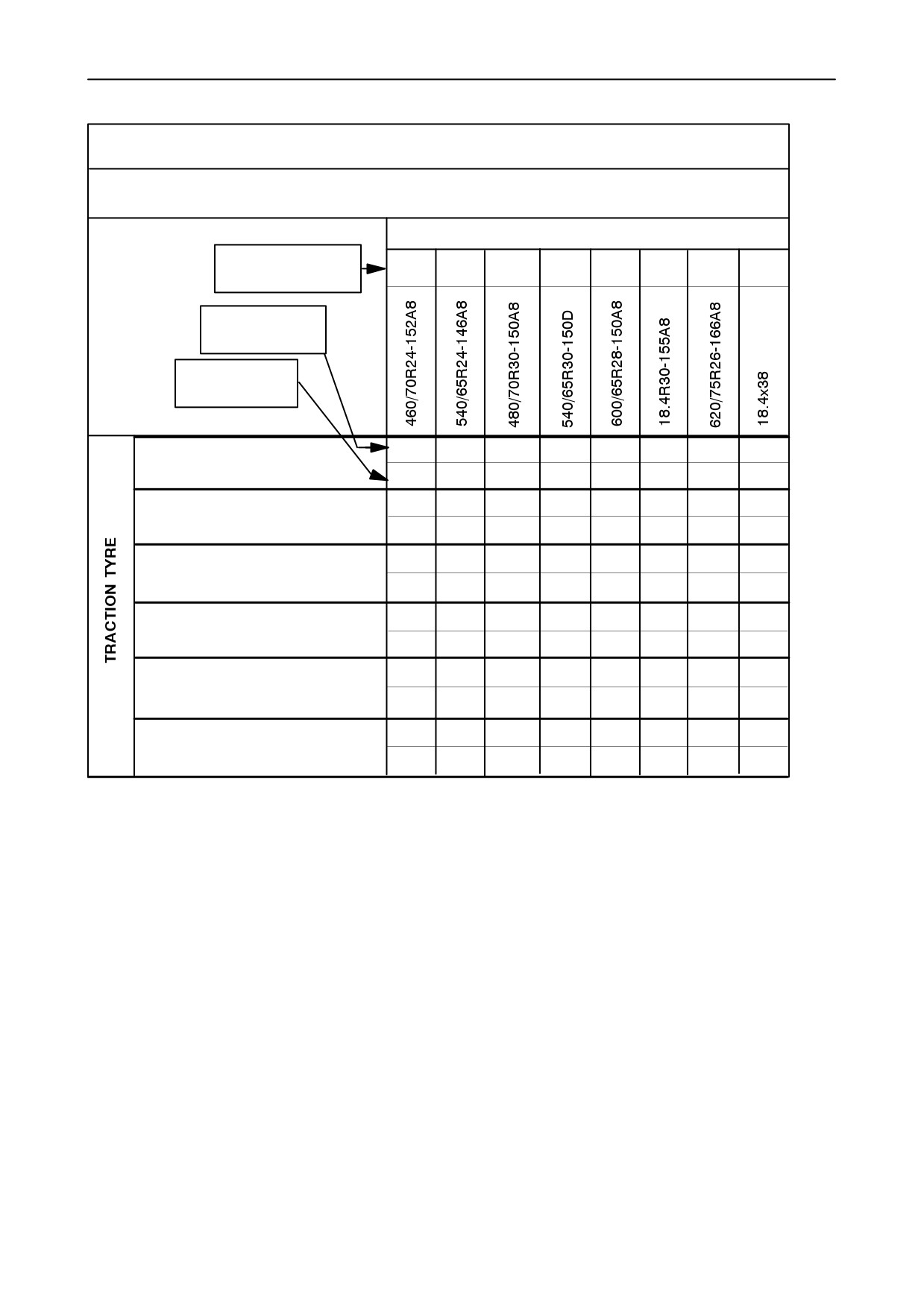
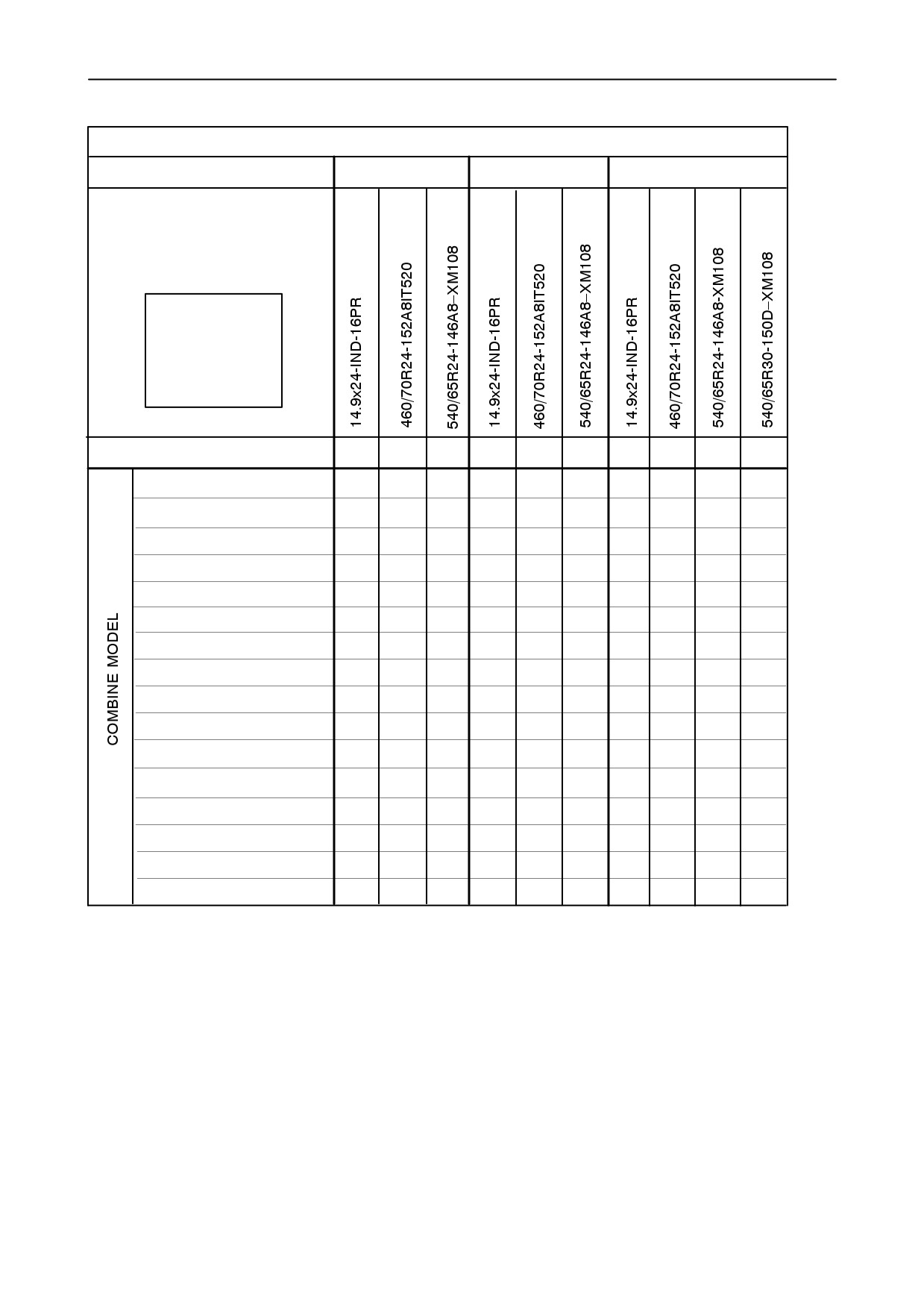
CX720-740-760: TRACK WIDTH POSITION: P.R.A. (Europe)
ASSEMBLY POSITION OF STEERING ARM ASSY AND MINIMUM TRACK WIDTH POSITION
STEERING TYRE
Axial position of
the steering axle
F
F
F
F
F
R
R
R
Height position
detail nr.
Minimum track
width position
4
4
650/75R32-172A8-DT822
1
1
4
710/75R34-178A8-Megaxbib
1
4
4
2
2
800/65R32-172A8-DT822
1
1
2
2
4
3
3
3
2
900/60R32-176A8-DT830
1
2
2
2
2
3
3
3
2
2
1050/50R32-178A8-MegaXbi
2
2
2
2
4
4
4
4
3
TRACKS INTERTRACTOR
3
3
3
4
“R” : Rear position of the steering axle
“F” : Front position of the steering axle
4-94
SECTION 4 - LUBRICATION AND MAINTENANCE
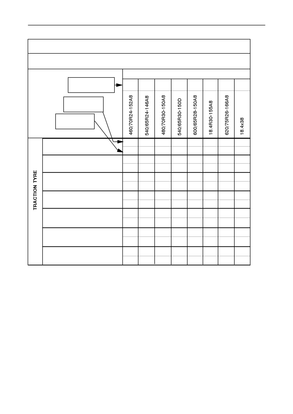
CX780: TRACK WIDTH POSITION: P.R.A. (Europe+Not Europe)
ASSEMBLY POSITION OF STEERING ARM ASSY AND MINIMUM TRACK WIDTH POSITION
STEERING TYRE
Axial position of
F
F
F
F
F
R
R
R
the steering axle
Height position
detail nr.
Minimum track
width position
4
4
650/75R32-172A8-DT822
1
1
4
710/75R34-178A8-Megaxbib
1
4
4
2
2
800/65R32-172A8-DT822
1
1
2
2
4
3
3
3
2
900/60R32-176A8-DT830
1
2
2
2
2
3
3
3
2
2
1050/50R32-178A8-MegaXbi
2
2
2
2
4
3
3
3
3
900/65R32-172A8-TD8
2
2
2
2
4
4
4
3
TRACKS INTERTRACTOR
3
3
3
4
“R” : Rear position of the steering axle
“F” : Front position of the steering axle
4-95
SECTION 4 - LUBRICATION AND MAINTENANCE
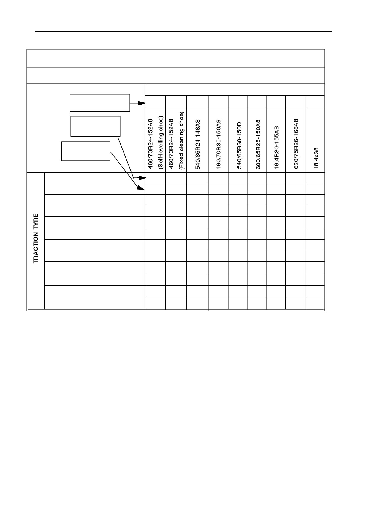
CX820-840-860-880: TRACK WIDTH POSITION: P.R.A. (Europe)
ASSEMBLY POSITION OF STEERING ARM ASSY AND MINIMUM TRACK WIDTH POSITION
STEERING TYRE
Axial position of
F
F
F
F
F
F
R
R
R
the steering axle
Height position
detail nr.
Minimum track
width position
4
4
4
650/75R32-172A8-DT822
3
2
3
4
710/75R34-178A8-Megaxbib
2
4
4
4
2
2
1
800/65R32-172A8-DT822
3
2
3
4
4
4
4
3
3
3
2
900/60R32-176A8-DT830
3
4
4
4
4
3
3
3
2
2
1050/50R32-178A8-MegaXbi
4
4
4
4
6
4
4
4
3
TRACKS INTERTRACTOR
5
5
5
6
“R” : Rear position of the steering axle
“F” : Front position of the steering axle
4-96
SECTION 4 - LUBRICATION AND MAINTENANCE
CX860-880: TRACK WIDTH POSITION: P.R.A. (Not Europe)
ASSEMBLY POSITION OF STEERING ARM ASSY AND MINIMUM TRACK WIDTH POSITION
STEERING TYRE
Axial position of
F
F
F
F
F
F
R
R
R
the steering axle
Height position
detail nr.
Minimum track
width position
4
4
4
2
2
2
1
650/75R32-172A8-DT822
3
2
3
4
4
5
4
4
4
4
2
2
2
1
1
800/65R32-172A8-DT822
3
2
3
4
4
5
4
6
4
4
3
3
3
2
2
900/60R32-176A8-DT830
3
3
4
4
4
4
6
3
3
2
900/65R32-172A8-TD8
4
5
6
3
3
3
2
2
1050/50R32-178A8-MegaXbi
4
4
4
4
6
2
2
2
2
1
1
2x18.4R42-153A8-RAT23
4
4
5
4
6
6
3
3
3
2
2
2
2x20.8R42-155A8-STR
4
4
4
4
6
6
3
3
3
2
2
1
2x20.8R42-155A8-TD8
4
4
4
4
6
6
“R” : Rear position of the steering axle
“F” : Front position of the steering axle
(Only with offset out : bolded)
4-97
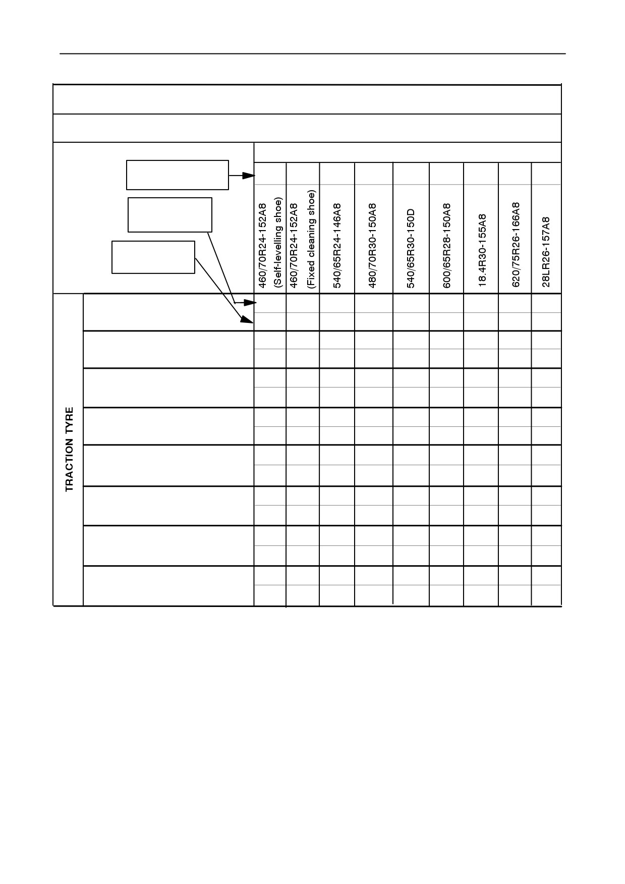
SECTION 4 - LUBRICATION AND MAINTENANCE
ROAD SPEED LIMITATION FOR TRACTION TYRES ON CX720-740-760
TRACTION TYRE
ROAD
TRANSPORT
NOT
ALLOWED
WITH (x)
offset
148
60
-75
38
88
8
-115
-23
-115
-118
III at 0-20km/h
III at 21-25km/h
III at 26-30km/h
III at 31-40km/h
x
x
x
x
x
IV at 0-20km/h
IV at 21-25km/h
IV at 26-30km/h
x
IV at 31-40km/h
x
x
x
x
x
V at 0-20km/h
x
x
x
x
x
x
x
x
x
x
V at 21-25km/h
x
x
x
x
x
x
x
x
x
x
V at 26-30km/h
x
x
x
x
x
x
x
x
x
x
V at 31-40km/h
x
x
x
x
x
x
x
x
x
x
IMPORTANT: All speed values are nominal values
III: header weight between 1850 (4078 lbs) and
2000 kg (4409 lbs)
(6-row rigid with chopper)
HEADER CLASSIFICATION
IV: header weight between 2000 (4409) and 2250 kg
(4960 lbs)
I: maximum header weight = 1500kg (3307 lbs)
(30 ft / 6-row flip-up / 6-row flip-up with chopper)
Up to 20 ft (NH header)
V: header weight between 2250 (4960) and 2750 kg
II: header weight between 1500 (3307) and 1850 kg
(6062 lbs)
(4078 lbs)
36 ft / 30 ft with rape seed extension / 8-row with
(24 ft / 5-row / 5-row with chopper / 6-row rigid)
chopper / 8-row flip-up / 8-row flip-up with chopper)
4-98
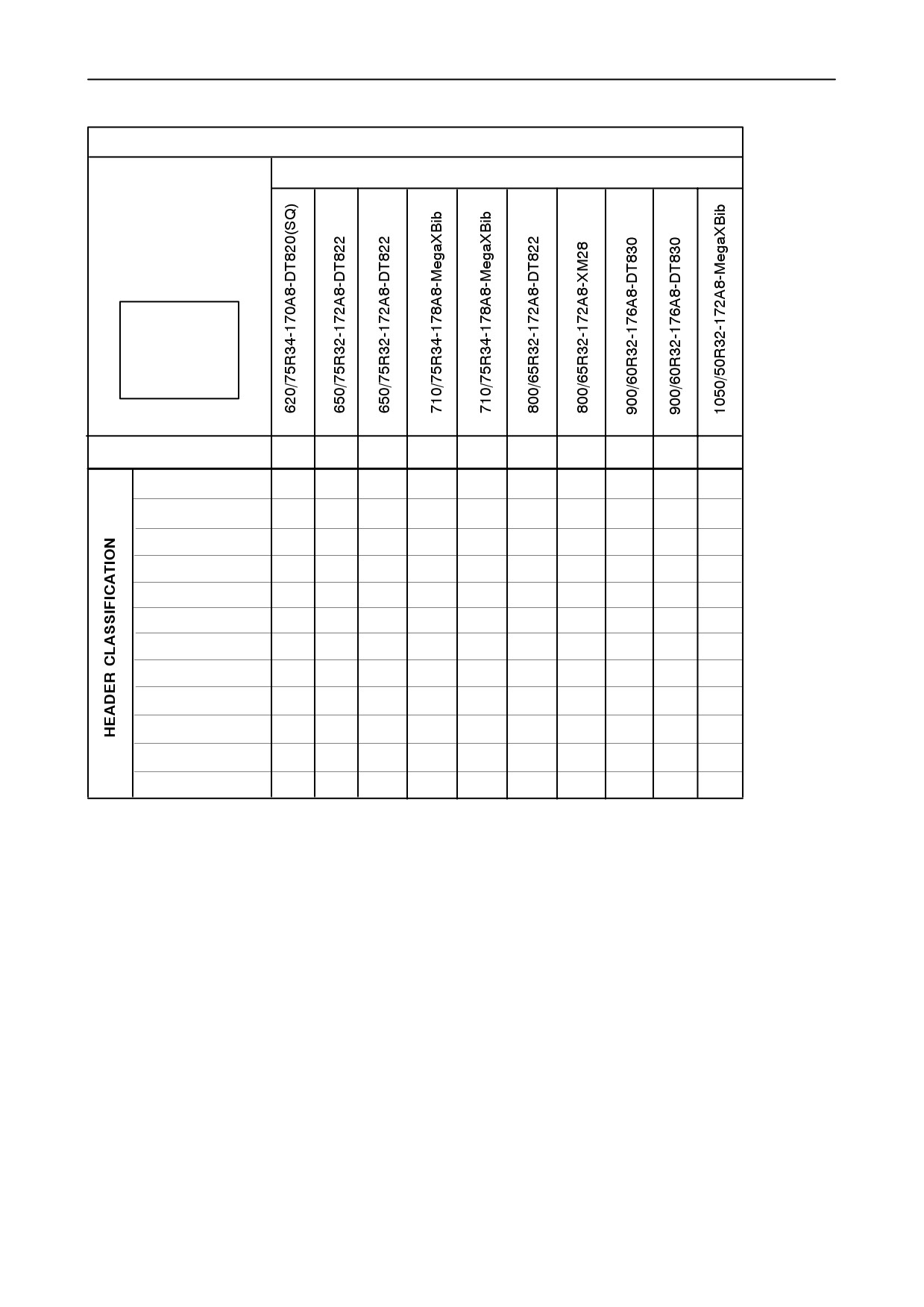
SECTION 4 - LUBRICATION AND MAINTENANCE
ROAD SPEED LIMITATION FOR TRACTION TYRES ON CX780
TRACTION TYRE
ROAD
TRANSPORT
NOT
ALLOWED
WITH (x)
offset
148
60
-75
38
88
8
-115
-23
-115
-118
-115
III at 0-20km/h
III at 21-25km/h
III at 26-30km/h
III at 31-40km/h
x
x
x
x
x
x
IV at 0-20km/h
IV at 21-25km/h
IV at 26-30km/h
x
IV at 31-40km/h
x
x
x
x
x
x
V at 0-20km/h
V at 21-25km/h
x
x
x
x
x
x
V at 26-30km/h
x
x
x
x
x
x
V at 31-40km/h
x
x
x
x
x
x
IMPORTANT: All speed values are nominal values
III: header weight between 1850 (4078 lbs) and
2000 kg (4409 lbs)
(6-row rigid with chopper)
HEADER CLASSIFICATION
IV: header weight between 2000 (4409) and 2250 kg
(4960 lbs)
I: maximum header weight = 1500kg (3307 lbs)
(30 ft / 6-row flip-up / 6-row flip-up with chopper)
Up to 20 ft (NH header)
V: header weight between 2250 (4960) and 2750 kg
II: header weight between 1500 (3307) and 1850 kg
(6062 lbs)
(4078 lbs)
36 ft / 30 ft with rape seed extension / 8-row with
(24 ft / 5-row / 5-row with chopper / 6-row rigid)
chopper / 8-row flip-up / 8-row flip-up with chopper)
4-99
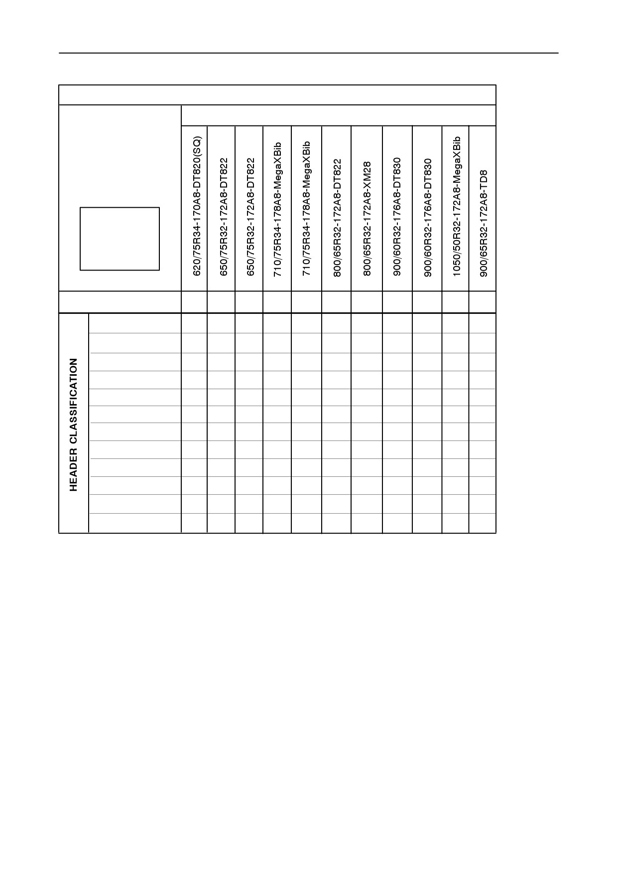
SECTION 4 - LUBRICATION AND MAINTENANCE
ROAD SPEED LIMITATION FOR TRACTION TYRES ON CX820-840
TRACTION TYRE
ROAD
TRANSPORT
NOT
ALLOWED
WITH (x)
offset
118
130
60
-115
58
8
-115
-23
-115
-118
-115
365
381
267
III at 0-20km/h
III at 21-25km/h
III at 26-30km/h
x
III at 31-40km/h
x
x
x
x
x
x
x
x
IV at 0-20km/h
IV at 21-25km/h
x
IV at 26-30km/h
x
x
x
x
x
x
x
IV at 31-40km/h
x
x
x
x
x
x
x
x
V at 0-20km/h
V at 21-25km/h
x
x
x
x
x
x
x
x
V at 26-30km/h
x
x
x
x
x
x
x
x
x
V at 31-40km/h
x
x
x
x
x
x
x
x
x
x
x
x
x
IMPORTANT: All speed values are nominal values
III: header weight between 1850 (4078 lbs) and
2000 kg (4409 lbs)
(6-row rigid with chopper)
HEADER CLASSIFICATION
IV: header weight between 2000 (4409) and 2250 kg
(4960 lbs)
I: maximum header weight = 1500 kg (3307 lbs)
(30 ft / 6-row flip-up / 6-row flip-up with chopper)
Up to 20 ft (NH header)
V: header weight between 2250 (4960) and 2750 kg
II: header weight between 1500 (3307) and 1850 kg
(6062 lbs)
(4078 lbs)
36 ft / 30 ft with rape seed extension / 8-row with
(24 ft / 5-row / 5-row with chopper / 6-row rigid)
chopper / 8-row flip-up / 8-row flip-up with chopper)
4-100
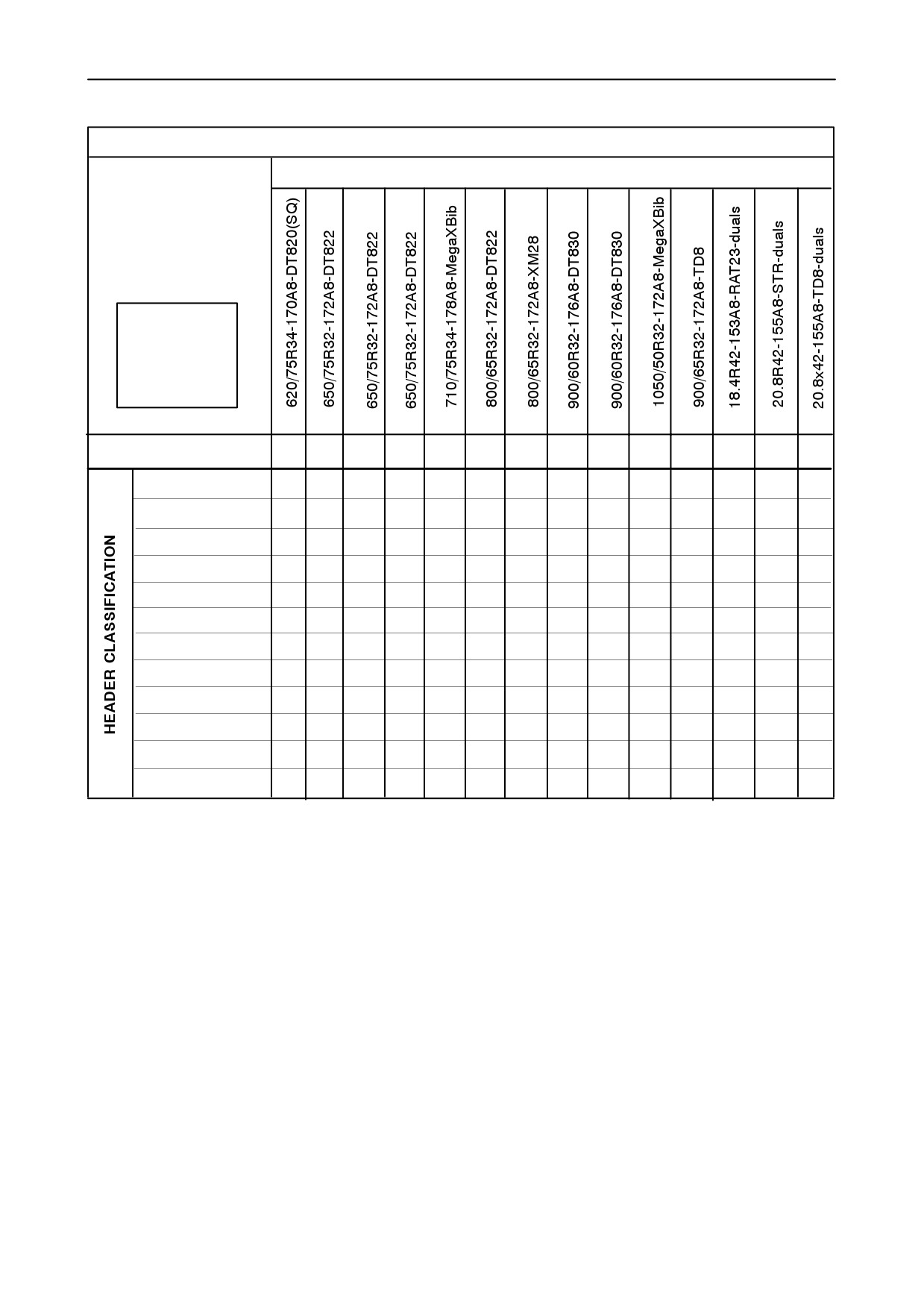
SECTION 4 - LUBRICATION AND MAINTENANCE
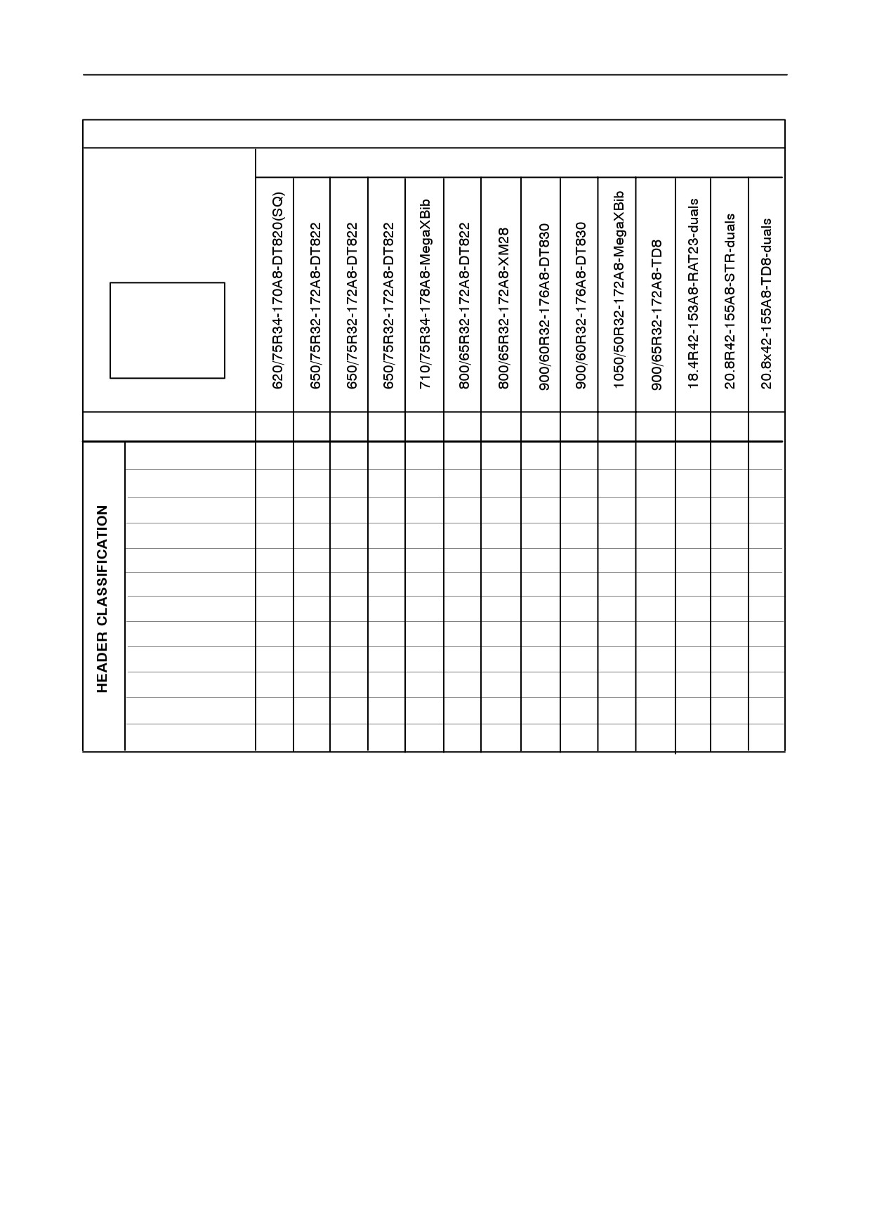
ROAD SPEED LIMITATION FOR TRACTION TYRES ON CX860
TRACTION TYRE
ROAD
TRANSPORT
NOT
ALLOWED
WITH (x)
offset
118
130
60
-115
58
8
-115
-23
-115
-118
-115
365
381
267
III at 0-20km/h
III at 21-25km/h
III at 26-30km/h
x
III at 31-40km/h
x
x
x
x
x
x
x
x
IV at 0-20km/h
IV at 21-25km/h
x
IV at 26-30km/h
x
x
x
x
x
x
x
x
IV at 31-40km/h
x
x
x
x
x
x
x
x
x
V at 0-20km/h
x
V at 21-25km/h
x
x
x
x
x
x
x
x
V at 26-30km/h
x
x
x
x
x
x
x
x
x
x
V at 31-40km/h
x
x
x
x
x
x
x
x
x
x
x
x
x
IMPORTANT: All speed values are nominal values
III: header weight between 1850 (4078 lbs) and
2000 kg (4409 lbs)
(6-row rigid with chopper)
HEADER CLASSIFICATION
IV: header weight between 2000 (4409) and 2250 kg
(4960 lbs)
I: maximum header weight = 1500 kg (3307 lbs)
(30 ft / 6-row flip-up / 6-row flip-up with chopper)
Up to 20 ft (NH header)
V: header weight between 2250 (4960) and 2750 kg
II: header weight between 1500 (3307) and 1850 kg
(6062 lbs)
(4078 lbs)
36 ft / 30 ft with rape seed extension / 8-row with
(24 ft / 5-row / 5-row with chopper / 6-row rigid)
chopper / 8-row flip-up / 8-row flip-up with chopper)
4-101
SECTION 4 - LUBRICATION AND MAINTENANCE
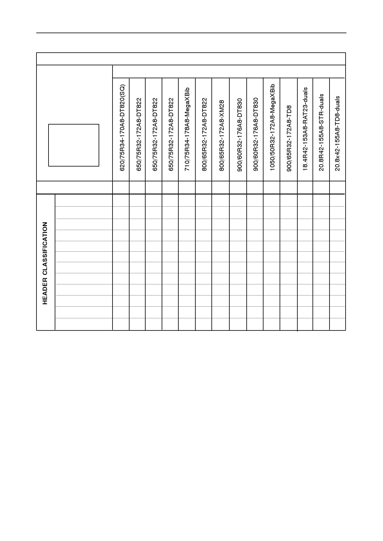
ROAD SPEED LIMITATION FOR TRACTION TYRES ON CX880
TRACTION TYRE
ROAD
TRANSPORT
NOT
ALLOWED
WITH (x)
offset
118
130
60
-115
58
8
-115
-23
-115
-118
-115
365
381
267
III at 0-20km/h
III at 21-25km/h
x
III at 26-30km/h
x
III at 31-40km/h
x
x
x
x
x
x
x
x
IV at 0-20km/h
IV at 21-25km/h
x
IV at 26-30km/h
x
x
x
x
x
x
x
x
IV at 31-40km/h
x
x
x
x
x
x
x
x
x
x
V at 0-20km/h
x
V at 21-25km/h
x
x
x
x
x
x
x
x
V at 26-30km/h
x
x
x
x
x
x
x
x
x
x
V at 31-40km/h
x
x
x
x
x
x
x
x
x
x
x
x
x
IMPORTANT: All speed values are nominal values
III: header weight between 1850 (4078 lbs) and
2000 kg (4409 lbs)
(6-row rigid with chopper)
HEADER CLASSIFICATION
IV: header weight between 2000 (4409) and 2250 kg
(4960 lbs)
I: maximum header weight = 1500 kg (3307 lbs)
(30 ft / 6-row flip-up / 6-row flip-up with chopper)
Up to 20 ft (NH header)
V: header weight between 2250 (4960) and 2750 kg
II: header weight between 1500 (3307) and 1850 kg
(6062 lbs)
(4078 lbs)
36 ft / 30 ft with rape seed extension / 8-row with
(24 ft / 5-row / 5-row with chopper / 6-row rigid)
chopper / 8-row flip-up / 8-row flip-up with chopper)
4-102
SECTION 4 - LUBRICATION AND MAINTENANCE
ROAD SPEED LIMITATION FOR STEERING TYRES
Steering axle
FIXED
H.D.A.S.A.
P.R.A.
ROAD
TRANSPORT
NOT
ALLOWED
WITH (x)
Offset
45
-10
-60
45
-10
-60
45
70
49
39
CX720/740/760
0-20km/h
21-25km/h
26-30km/h
x
CX780
0-20km/h
21-25km/h
x
26-30km/h
x
x
x
CX820/840/860
0-20km/h
x
21-25km/h
x
x
x
x
26-30km/h
x
x
x
x
x
x
x
CX880
0-20km/h
x
21-25km/h
x
x
x
x
26-30km/h
x
x
x
x
x
x
x
4-103
SECTION 4 - LUBRICATION AND MAINTENANCE
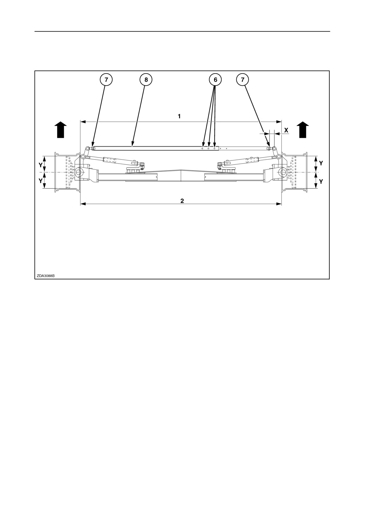
5. Toe-in adjustment
205
The steering wheels should have the correct amount
of toe-in, otherwise premature tyre wear may occur.
The distance between the steering wheels must be
smaller at the front than at the rear.
(facing the direction of travel).
4-104
SECTION 4 - LUBRICATION AND MAINTENANCE
To check and adjust the toe-in, proceed as follows:
1. Apply the parking brake and support the steering
axle so that the steering wheels are clear of the
ground.
CAUTION
Use suitable jack stands, securely positioned
underneath the rear of the machine, before adjusting
the steering axle.
2. Set the steering wheels in the straight-ahead
position.
3. Mark spots at “Y”= 300 mm (11 - 13/16”) from the
centre on the front inside of the wheel rims at the
centre-of-wheel height and measure distance “1”.
4. Turn the steering wheels
180° forward or
rearward until the marks are at the
centre-of-wheel height and measure distance “2”.
Distance “2” must be 8 to 12 mm (5/16” to 15/32”)
bigger than distance “1”.
5. To adjust the toe-in, loosen jam nuts 7 on both
sides and remove the three bolts 6 in the steering
rod 8.
6. Turn the two tubes on their ball joints. The two
tubes must be rotated in opposite directions and
even on both sides.
IMPORTANT: Check that dimension “X” = maximum
80 mm (3 - 1/8”) on both sides of the steering rod.
7. After adjustment, tighten the three bolts 6 with a
torque between 15 and 20 Nm. (11 and 15 ft.lbs)
without deformation of the inner tube.
8. Tighten the both jam nuts 7 with a torque between
290 - 310 Nm (214 - 229ft.lbs.)
4-105
SECTION 4 - LUBRICATION AND MAINTENANCE
6. Steering cylinder adjustment
To adjust the steering cylinders, proceed as follows:
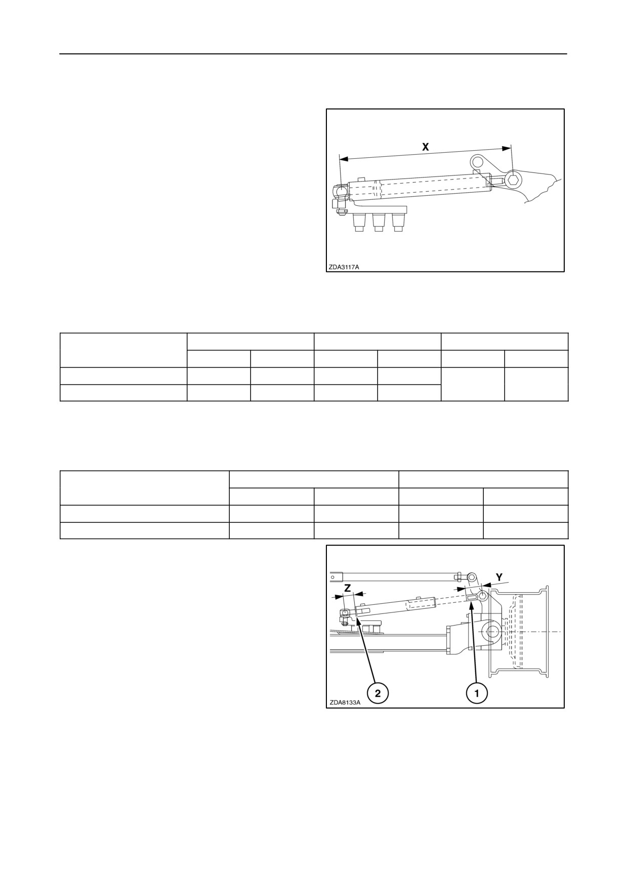
1. After adjusting the toe-in, adjust distance “X” of
the both cylinders. (Distance “X” = centre to
centre balljoint of the cylinder completely
retracted) see table.
206
P.R.A.
H.D.A.S.A.
FIXED
Height position
X (mm)
X (inches)
X (mm)
X (inches)
X (mm)
X (inches)
1
759
29-14/16”
728
28-21/32”
752
29-5/8”
2 3 4
753
29-5/8”
722
28-1/2”
In case a cylinder for SmartSteert system is
installed
P.R.A.
H.D.A.S.A.
Height position
X (mm)
X (inches)
X (mm)
X (inches)
1
769
30-1/4”
738
29-1/16”
2 3 4
763
30
732
28-13/16”
IMPORTANT: Check if:
Distance “Y” maximum = 120 mm (4 - 3/4”)
Distance “Z” minimum
- (H.D.A.S.A) = 50 mm (1- 31/32”)
- (P.R.A) = 70 mm (2 - 3/4”)
Distance “Z” maximum = 80 mm (3 - 1/8”)
2. After adjustment, tighten the nut 1 with a torque
between 190 and 210 Nm (140 and 155 ft.lbs) and
the nut 2 with a torque between 290 and 310 Nm.
(214 and 229 ft.lbs.)
207
4-106
SECTION 4 - LUBRICATION AND MAINTENANCE
ELECTRICAL SYSTEM
Fuses and relays
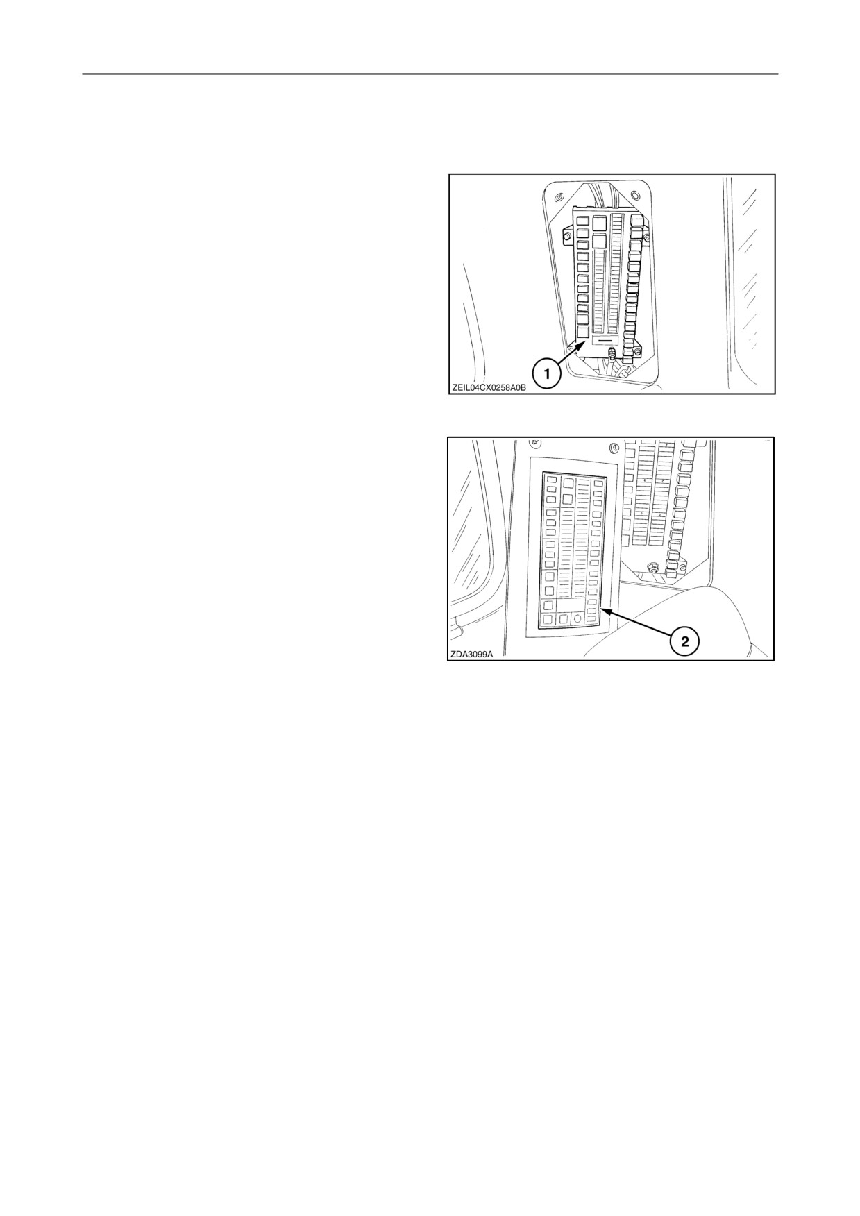
All fuses and relays are situated in the back left corner
of the cab.
IMPORTANT: When replacing a fuse, make sure the
new fuse has the same ampere rating as the fuse
being replaced.
A box 1 is foreseen for spare fuses.
208
IMPORTANT: When replacing a relay, make sure the
new relay has the same ampere rating and the same
structure (visible on the relay housing). Always use
genuine parts.
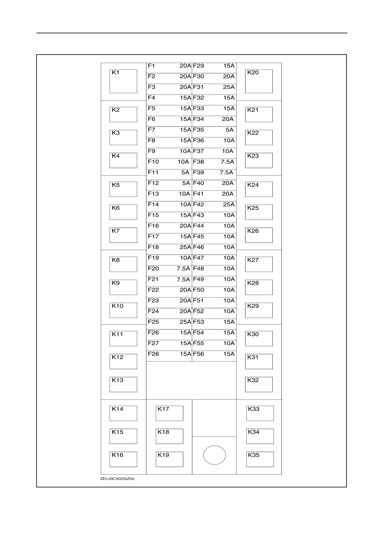
An overview of the fuses and relays (inside the
Operator’s Manual) can be installed on the inside of
cover 2.
209
4-107
SECTION 4 - LUBRICATION AND MAINTENANCE
210
4-108

SECTION 4 - LUBRICATION AND MAINTENANCE
Fuse n_
Amperage
Function
F1
20A
ECU power
F2
20A
Accessory 2
F3
20A
Accessory 1
F4
15A
Wiper
F5
15A
Cigar lighter
F6
15A
Left-hand cab operating lights
F7
15A
Right-hand cab operating lights
F8
15A
Accessory outlet
F9
10A
Washer/Mirror
F10
10A
Accessory socket
F11
5A
Radio
F12
5A
Global Positioning System
F13
10A
Tranceiver
F14
10A
Service lights
F15
15A
Service sockets
F16
20A
Seat pump
F17
15A
Separator blower
F18
25A
Main blower
F19
10A
A/C clutch
F20
7.5A
Left-hand marker lights
F21
7.5A
Right-hand marker lights
F22
20A
Shoe levelling actuator
F23
20A
Throttle/brush/reel variator
F24
20A
Reverser/Fan
F25
25A
Transmission gearshift motor
F26
15A
HGS turntable (SmartSteert)
F27
15A
Sieves/Chopper
F28
15A
Fuel pump
4-109

SECTION 4 - LUBRICATION AND MAINTENANCE
Fuse n_
Amperage
Function
F29
15A
Distance operating lights
F30
20A
Header operating lights
F31
25A
Cab roof operating lights
F32
15A
High beam
F33
15A
Low beam
F34
20A
Under shield lights
F35
5A
Radio
F36
10A
Combine Control Module 2A
F37
10A
Combine Control Module 2B
F38
7.5A
Key switch
F39
7.5A
Memory/ka power
F40
20A
Combine Control Module 1
F41
20A
Combine Control Module 2
F42
25A
Combine Control Module 3/Cab
F43
10A
Combine Control Module 1A
F44
10A
Combine Control Module 1B
F45
10A
Header Height Control power
F46
10A
Hydraulic reel drive
F47
10A
Combine Control Module 3 (precision farming/SmartSteert)
F48
10A
Right-hand module
F49
10A
Cab/HGS sensor (SmartSteert)
F50
10A
Side/Tube lights
F51
10A
Horn/Marker lights
F52
10A
Dome/Brake lights
F53
15A
Revolving flash light(s)
F54
15A
Lower operating lights
F55
10A
Rear operating lights
F56
15A
Hazard lights
4-110

SECTION 4 - LUBRICATION AND MAINTENANCE
Relay n_
Function
K1
Cab roof operating lights
K2
Light control
K3
Accessory 2
K4
High beam
K5
Low beam
K6
Wiper motor
K7
Fuel pump
K8
Accessory 1
K9
Separator blower
K10
A/C clutch
K11
A/C Main blower high
K12
A/C Main blower medium
K13
A/C Main blower low
K14
Engine Control Unit
K15
Start relay
K16
Concave/covers
K17
Fan/reverser
K18
Upper/Lower sieve
K19
Not used
K20
Time delay
K21
Distance operating lights
K22
Header operating lights
K23
Neutral start
K24
Combine Control Module 1
K25
Combine Control Module 2
K26
Combine Control Module 3 / Cab / SmartSteert
K27
Not used
K28
Threshing latching
K29
Revolving flash lights
K30
Lower operating lights
K31
Rear operating lights
K32
Unload tube light
K33
Brake lights
K34
Timed side operating light
K35
Side operating lights
K36
-
K37
Grid heater (CNH engine)
K38
24 Volt start relay (Iveco engine)
K39
Grid heater (Iveco engine)
4-111
SECTION 4 - LUBRICATION AND MAINTENANCE
COMBINE CONTROL MODULE (CCM)
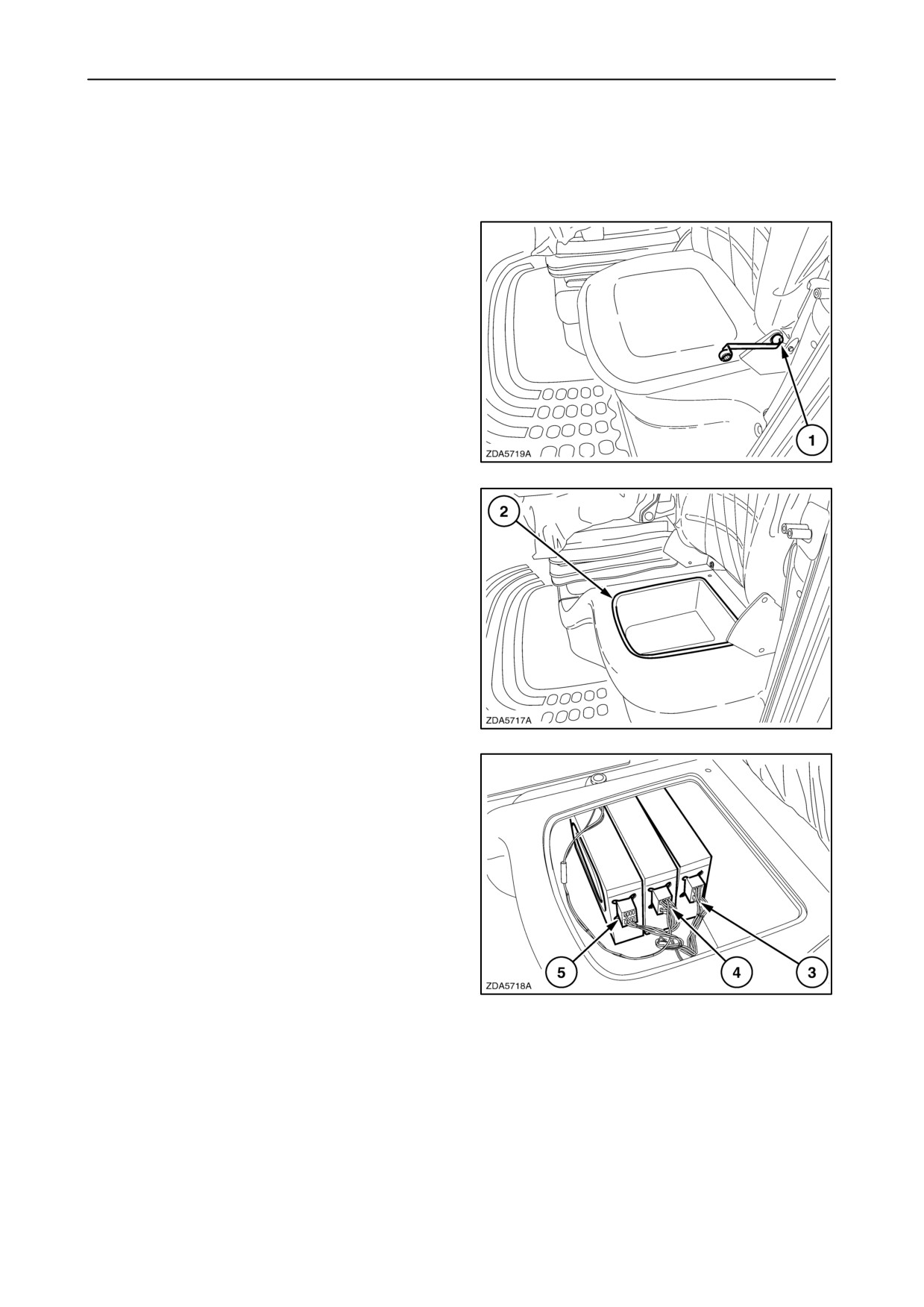
The CCM’s are located under the storage box of the
instructional seat.
To check this, proceed as follows:
1. Remove bolts 1 on both sides of the seat.
(if installed)
211
2. Take out storage box 2.
212
3. CCM 1
4. CCM 2
5. CCM 3 (If installed)
213
4-112
SECTION 4 - LUBRICATION AND MAINTENANCE
BATTERIES
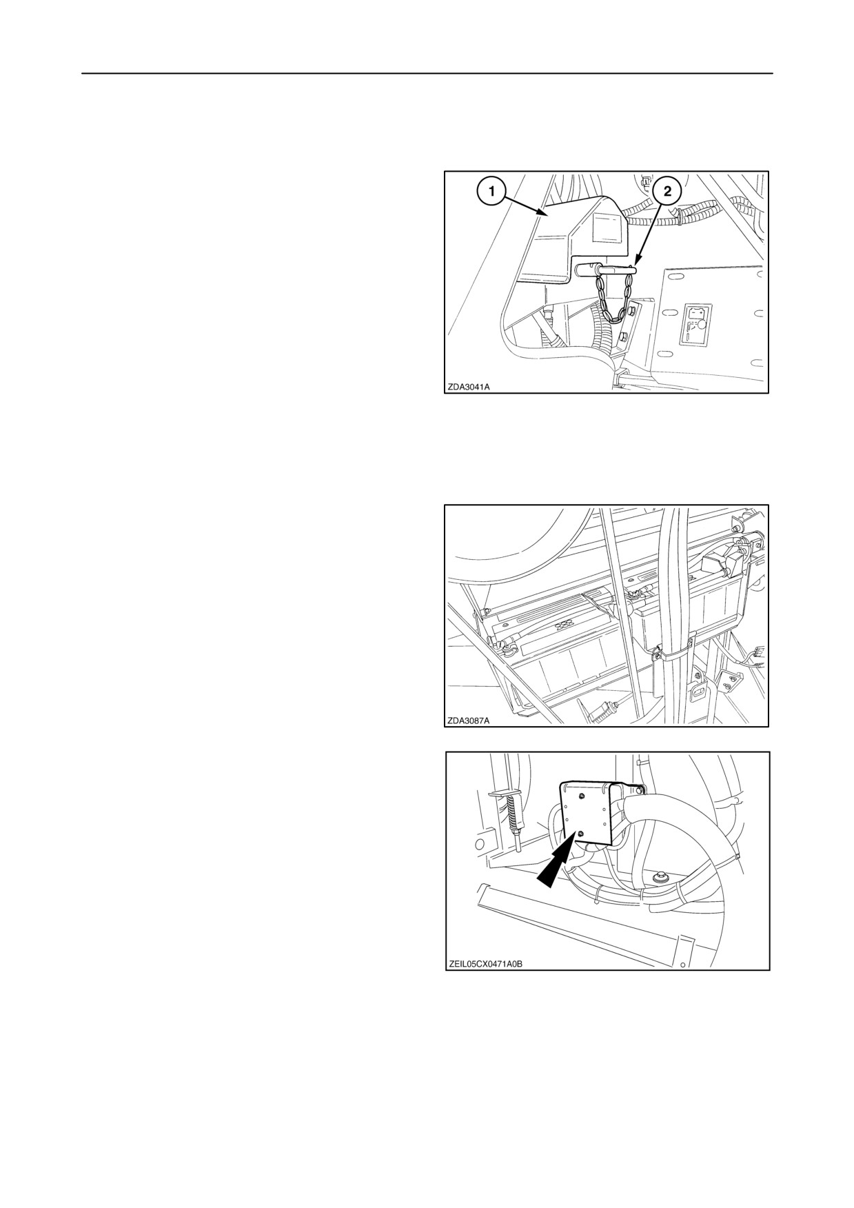
The combine is equipped with two 12 Volt batteries
(92 Ah). These are located at the back of the left-hand
side of the combine. Open cover 1 to have access to
the batteries.
The batteries can be disconnected completely by
means of the main battery switch 2.
IMPORTANT: To avoid loss of harvest data from the
InfoViewt monitor, engine power reduction and/or
permanent InfoViewt monitor damage, it is strongly
recommended not to stop the engine by using the
battery switch. Always use the contact key in this
case.
214
IMPORTANT: It is advisable to disconnect the
batteries at the end of the day using the battery
switch.
The earth cable is connected to the negative (-)
battery terminals.
Check the acid level weekly (every 50 operating
hours), and, if necessary, fill with distilled water until
the separators are covered.
215
NOTE: Models CX860 and CX880 are also equipped
with two 12V batteries (92Ah), connected parallel, but
switching to 24 V during starting.
216
4-113
SECTION 4 - LUBRICATION AND MAINTENANCE
Important tips
1. In cold weather, add water to the batteries just
before starting the engine. By doing this, the
water and the electrolyte will be mixed by the
charging current, thus avoiding freezing.
CAUTION
Keep sparks, lighted matches or an open flame away
from the battery as battery gas can explode.
Never check the battery charge by placing a metal
object across the terminals. Use a voltmeter or a
hydrometer.
2.
If the engine is reluctant to start, do not press the
starter button for longer than 20 seconds, but try
again after a few seconds.
3.
The battery clamps must be cleaned regularly
and covered with a layer of vaseline or petroleum
jelly to prevent corrosion.
4.
Make sure the vents in the filler plugs are kept
clean.
5.
The batteries must never be disconnected while
the engine is running, or permanent damage to
the alternator and the electronic systems may
result.
6.
Never switch off the ignition while the engine is
running on full speed. This is to prevent running
out of the turbocharger propeller without
lubricant.
7.
To safeguard battery life, switch off any lighting,
the heating/Ventilation/AC and the mirror heating
before starting the engine.
8.
Under normal conditions, do not add sulphuric
acid to the batteries.
9.
The batteries should be stored in a fully charged
condition.
10. The batteries should be charged every 8 to 10
weeks with 5 to 6 amperes current for a period of
24 hours.
CAUTION
Do not charge a frozen battery as it may explode!
4-114
SECTION 4 - LUBRICATION AND MAINTENANCE
ALTERNATOR
NOTE: The engine is equipped with an alternator.
Certain precautions must be observed to avoid
serious damage to the alternator, batteries and
wiring.
When carrying out any maintenance work, the
following instructions must be observed:
1. Disconnect the batteries using the battery switch
if any electric welding work is to be carried out on
the combine.
Secure the negative (-) terminal of the welding
apparatus as close as possible to the part to be
welded.
2. The positive (+) lead of the batteries is live at all
times. To prevent damage, always disconnect the
battery earth lead (-) first.
3. Ensure the batteries are connected properly, i.e.
negative (-) lead to the negative (-) terminal and
positive (+) lead to the positive (+) terminal.
4. Always connect a booster battery in parallel, i.e.
negative (-) to negative (-), and positive (+) to
positive (+).
5. Disconnect the batteries using the battery switch
before connecting a battery charger.
Ensure the battery charger is properly
connected.
6. Never run the engine if the wiring between the
alternator and the battery has been
disconnected.
4-115
SECTION 4 - LUBRICATION AND MAINTENANCE
CAB/CLIMATE CONTROL
Cab air filter
The cab air filter is located near the cab door on the
left hand side.
Clean the cab air filter regularly and, in extremely
dusty conditions, daily.
Wear a suitable dust mask!
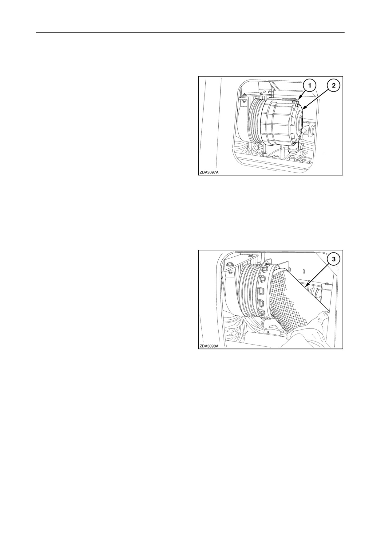
To remove the cab air filter, proceed as follows:
1. Pull yellow slider 1.
2. Cover 2 can be removed with a smooth twist to
the left, and than pulling it towards you.
217
3. Remove filter element 3.
4. Clean with compressed air blown from the inside
towards the outside.
It is advisable to replace the filter elements every
year.
Installation:
1. Install filter element 3 in the housing.
218
4-116
SECTION 4 - LUBRICATION AND MAINTENANCE
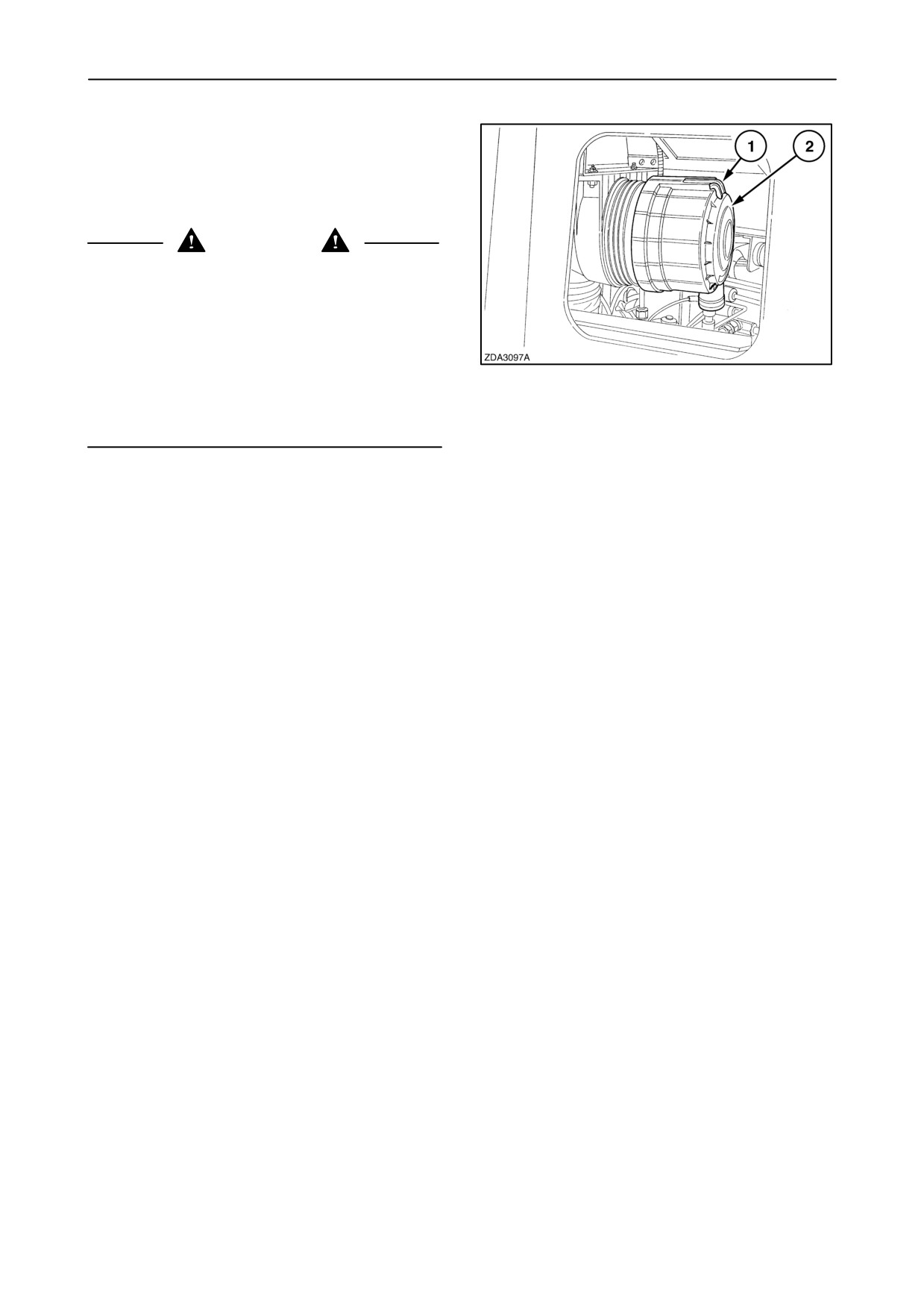
2. Install the cover. The dust outlet on the cover
should be pointed to the floor.
3. To close the housing turn cover 2 to the right till
it locks.
4. Lock the cover with yellow slider 1.
CAUTION
Dust protection: The air filter in the cab does not
protect against all substances
(e.g. chemical
residues on crops). Absolute protection against
specific products can only be obtained when the
nature of these products is known and adequate
measures are purposely designed to counter the
hazard created by these substances. Even the use of
219
carbon filters cannot ensure complete protection. It
goes without saying that correct filter maintenance
and keeping doors and windows closed is essential.
Air conditioning
For a correct use of the air-conditioning system:
• Keep the cab doors closed.
• Use the air conditioning as much as possible.
• Control the desired temperature with the
air-conditioning button (thermostat).
Pay regular attention to the following:
• The status of the sight glass and the moisture
indicator, on the filter drier, located on the engine
fan area.
• The cleanness of the condenser, located on the
engine rotary screen door.
• The cleanness of the cab fresh air filter located
under the left front corner of the grain tank.
• The cleanness of the cab air recirculation filter,
located on the right-hand rear cab wall beside the
operator seat.
• The condensation water flowing from the drain
tubes, check valves in humid conditions.
4-117