New Holland CX720, CX740, CX760, CX780, CX820, CX840, CX860, CX880. Operator's Manual - page 10
Brakes
4-79
Foot brakes
4-79
Parking brake
4-79
Fluid change
4-79
Hydraulic equipment
4-80
Tracks (If installed)
4-81
Steering axle
4-83
1. Steering axle position
4-84
2. Axial position of the steering axle
4-84
3. Steering axle height position
4-86
4. Track width position
4-87
5. Toe-in adjustment
4-104
6. Steering cylinder adjustment
4-106
Electrical system
4-107
Fuses and relays
4-107
Combine Control Module (CCM)
4-112
Batteries
4-113
Alternator
4-115
Cab/Climate control
4-116
Cab air filter
4-116
Air conditioning
4-117
Condenser
4-118
Fresh air intake grill
4-118
Recirculation filter
4-118
Filter-drier
4-119
Air compressor (if installed)
4-120
Air reservoir specification
4-121
SECTION 5 - FAULT FINDING
Feeding area
5-1
Threshing area
5-1
Threshing, Separation and Cleaning
5-3
General
5-7
Engine
5-8
Straw Chopper
5-9
Powered Rear Axle
5-10
Manual release of the hydraulic parking brake
5-11
Gearshifting
5-12
Hydraulic valve electrics
5-14
SECTION 6 - VEHICLE STORAGE
End-Of-Season Service
6-1
Ordering Parts and/or Accessories
6-2
Preseason Service
6-3
SECTION 7 - ACCESSORIES
Feeding
7-1
Side hill weights
7-1
Crop distribution kit
7-1
Hydraulic reel rebuild kit
7-1
Grain header road light kit
7-2
viii
Perforated straw elevator floor section
7-2
Straw elevator drive
7-2
Intermediate roll
7-2
Header lift cylinder kit
7-3
Narrowing plates
7-3
Potentiometer for flex header 19 ft
7-3
Threshing and Separation
7-4
De-awning slats
7-4
Rice pins
7-4
Tool to remove the concave
7-4
Vertical knife electricity kit
7-5
Sunflower cover plate
7-5
Beater pins
7-5
Beater blades
7-5
Beater wear plates
7-5
Vertical covers on straw walkers
7-6
Straw walker raisers
7-6
Cereals threshing rebuild kit
7-6
Maize threshing rebuild kit
7-7
Rice threshing rebuild kit (if universal drum)
7-7
Maize concave
7-7
Cleaning system and lower frame
7-8
Remote sieve control
7-8
Fan bottom shield
7-8
Grass seed variator kit
7-8
Presieve HC 1-5/8”
7-9
Grain pan divider kit
7-9
Round hole sieve frame
7-9
Round hole sieve (16 or 18 mm)
7-9
Adjustable chaffer 1-5/8” and 1-1/8”
7-10
Adjustable upper sieve (Petersen 1-1/8”)
7-10
Closz upper sieve
7-10
Stainless steel curved louver maize upper sieve
7-10
Graepel sieve extension
7-10
Extended sieve dividers
7-11
Smooth rotor thresher covers
7-11
Clean grain, Grain tank and Unloading
7-12
Unloading tube extension kit
7-12
Perforated covers: Long or Round
7-12
Straw handling
7-13
Chaff blower
7-13
Chaff spreader
7-13
Straw chopper
7-14
Remote deflectors control
7-14
Straw chopper kit for maize
7-14
Straw chopper wind knife kit
7-14
Traction and tyres
7-15
Powered Rear Axle (wheel motors)
7-15
Dual speed (Powered Rear Axle II)
7-15
Axle extensions kit
7-15
Pivot plate 127 mm
7-16
Wheel spacer
7-16
Steering platform extensions
7-16
Tracks
7-16
ix
Foldable ladder
7-16
Engine
7-17
Air compressor kit
7-17
Coolant heater
7-17
Rotary dust screen brush
7-17
Fuel cooler
7-17
High fan speed kit
7-17
Cab
7-18
Windscreen washer system
7-18
In cab printer
7-18
Cab heating
7-18
Premium speakers
7-18
Electrical and Electronic
7-19
Flip-up light kit
7-19
Rear revolving flash light
7-19
Revolving flash lights
7-19
Portable work light
7-20
Light extension kit
7-20
Electronic module (CCM3)
7-20
Yield monitoring package
7-21
Yield mapping package
7-22
Yield logging package
7-23
SmartSteert system
7-23
Miscellaneous
7-24
Header trailer hitch
7-24
Counterweights support frame
7-25
Frame counterweights
7-25
Wheel counterweights
7-25
Signal plates
7-25
Signal plates for Italy
7-26
Unload tube signal plate+light
7-26
Fire extinguisher
7-26
Wide fender
7-26
SECTION 8 - SPECIFICATIONS
Wheels and tyres
8-1
Wheel nuts torque
8-1
Technical data
8-30
Dimensions
8-40
Dimension I (3)
8-42
Dimension J (3)
8-43
Dimension K (4)
8-43
Counterweights
8-44
SECTION 9 - 1ST 50 HOUR SERVICE SHEETS
Check and Adjust, as required (Customer copy)
9-1
Check and Adjust, as required (Dealer copy)
9-3
INDEX
x
SECTION 4 - LUBRICATION AND MAINTENANCE
SECTION 4 - LUBRICATION AND MAINTENANCE
GENERAL
Your combine is designed to require minimum
lubrication and maintenance. However, regular
lubrication and maintenance is the best insurance
against delays and repairs and greatly increases the
life of the machine.
Use only top grade lubricants stored in clean vessels.
Recommended lubricants and amounts are
summarized at the end of this section.
CAUTION
Always stop the machine before lubricating and
observe following precautions:
• Disengage all drives.
• Raise the header.
• Engage the header lifter safety latch.
• Engage the parking brake.
• Switch off the combine engine.
• Remove the ignition key before leaving the
operator’s platform.
GREASE FITTINGS AND INTERVALS
Before greasing the machine always wipe any dirt
from the grease fittings.
All points, except those with special notations, should
be lubricated until the grease is forced out around the
bearings and then the excess grease should be wiped
off.
NOTE: After greasing, shift the variators from
minimum to maximum and vice versa to distribute the
grease in the hub.
Grease specification
Use Multipurpose grease AMBRA GR9
(ref. (NH710A) or AMBRA GR75MD (ref. NH720A),
or grease classified under NLGI 2.
4-1
SECTION 4 - LUBRICATION AND MAINTENANCE
1
2
4-2
SECTION 4 - LUBRICATION AND MAINTENANCE
Grease interval
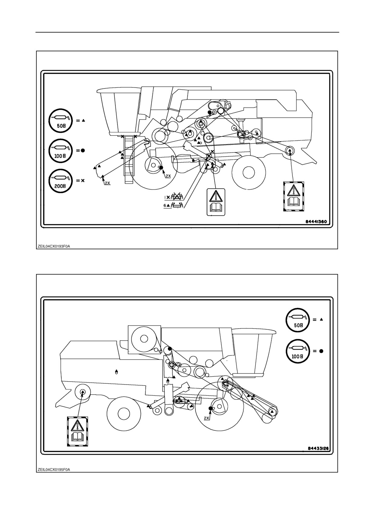
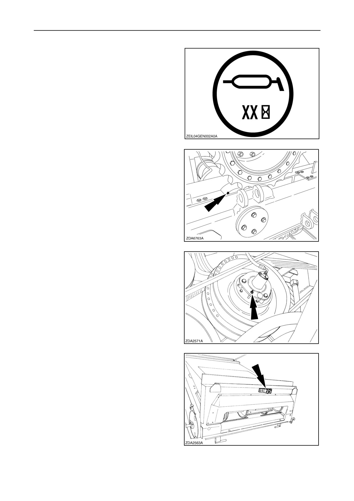
All grease fittings on the machine are indicated with
a grease decal on which the time interval “XX” is
mentioned.
NOTE: There is also a general grease decal foreseen
on both sides of your combine.
(see previous page)
3
10 hours interval
1. Tracks (If installed)
4
50 hours interval - left-hand side
1. Sliding sheave on driver drum variator
NOTE: Minimum 4 gun strokes every time the sheave
is greased.
NOTE: After greasing, shift the variator from
minimum to maximum and vice versa to distribute the
grease in the hub.
5
2. Pivot point lateral float
6
4-3
SECTION 4 - LUBRICATION AND MAINTENANCE
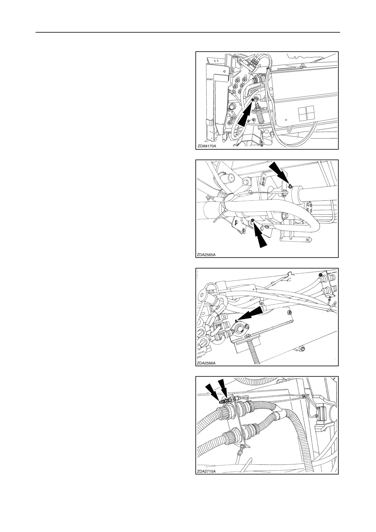
3. Straw elevator bottom shaft bearing
7
4. Sliding shaft reverser
5. Jaw clutch reverser (3x)
NOTE: Three grease zerks are installed to improve
access: Only one has to be greased.
8
6. Straw elevator intermediate roll bearing
(If installed)
9
7. Straw elevator top shaft bearing
8. Straw elevator top shaft bearing housing
10
4-4
SECTION 4 - LUBRICATION AND MAINTENANCE
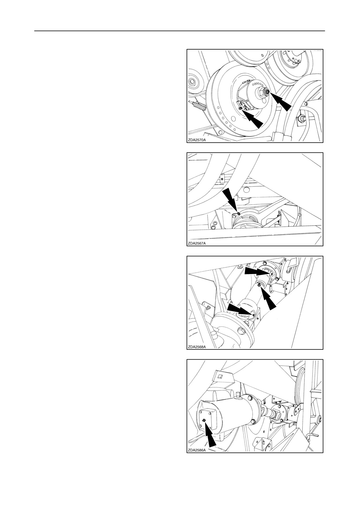
9. Sliding sheave on driven drum variator
NOTE: Minimum 4 gun strokes every time the sheave
is greased.
10. Thrust bearing on driven drum variator
NOTE: After greasing, shift the variator from
minimum to maximum and vice versa to distribute the
grease in the hub.
11
11. Eccentric hub cleaning shoe drive
12
12. P.t.o. (self levelling) cleaning shoe drive bottom
13. P.t.o. (self levelling) cleaning shoe drive top
14. P.t.o. (self levelling) cleaning shoe drive sliding
part
13
15. Cleaning shoe drive top gearbox (self levelling
cleaning shoe)
14
4-5
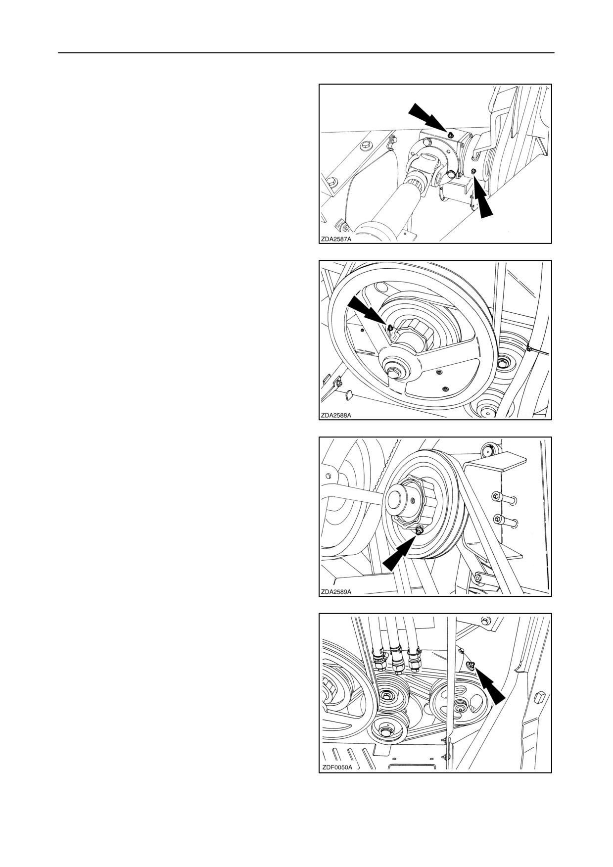
SECTION 4 - LUBRICATION AND MAINTENANCE
16. Cleaning shoe drive bottom gearbox
(self levelling cleaning shoe)
17. Cleaning shoe drive idler arm
15
18. Slip clutch returns drive (self levelling cleaning
shoe models)
NOTE: Maximum 2 gun strokes every time the clutch
is greased.
16
19. Slip clutch returns drive
(fixed cleaning shoe
models)
NOTE: Maximum 2 gun strokes every time the clutch
is greased.
17
20. Returns gearbox
18
4-6
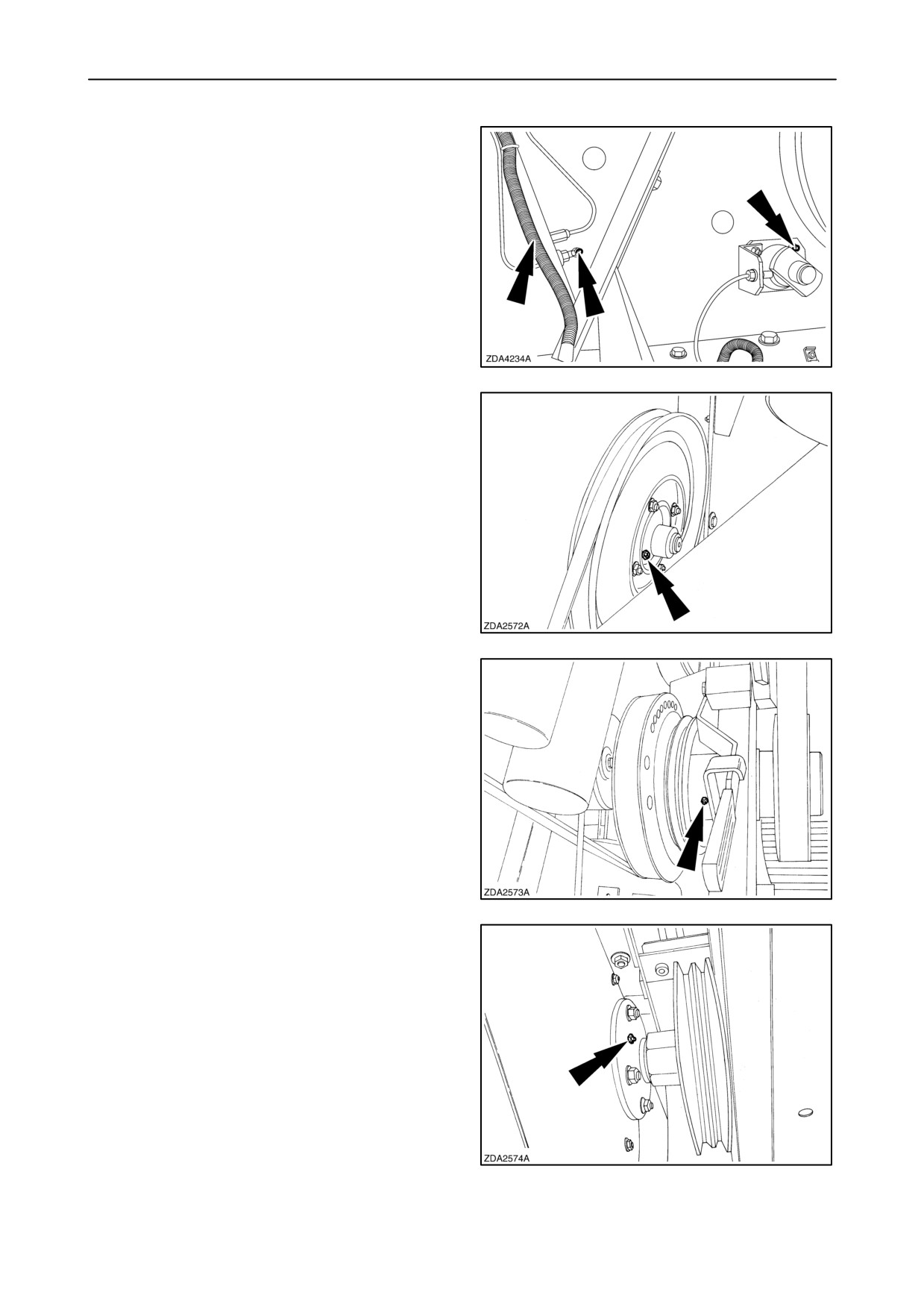
SECTION 4 - LUBRICATION AND MAINTENANCE
21. Straw flow beater shaft bearing
22. Conical bearing set on driven drum variator
23. Straw walker front shaft bearing
19
24. Straw walker rear shaft bearing
20
25. Straw chopper intermediate shaft
21
26. Straw chopper rotor bearing
NOTE: Maximum 2 gun strokes every time the
bearing is greased.
22
4-7
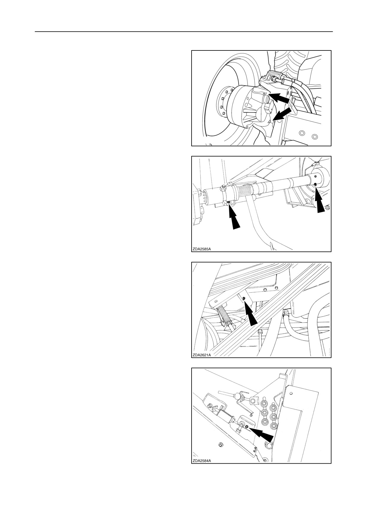
SECTION 4 - LUBRICATION AND MAINTENANCE
27. Powered rear axle upper and lower king pin
bushings. (If installed)
20021843
23
100 hours interval - left-hand side
1. Half shaft couplers traction (2x)
24
2. Pivot point of main drive idler arm
25
50 hours interval - right-hand side
1. Straw elevator bottom shaft bearing
26
4-8
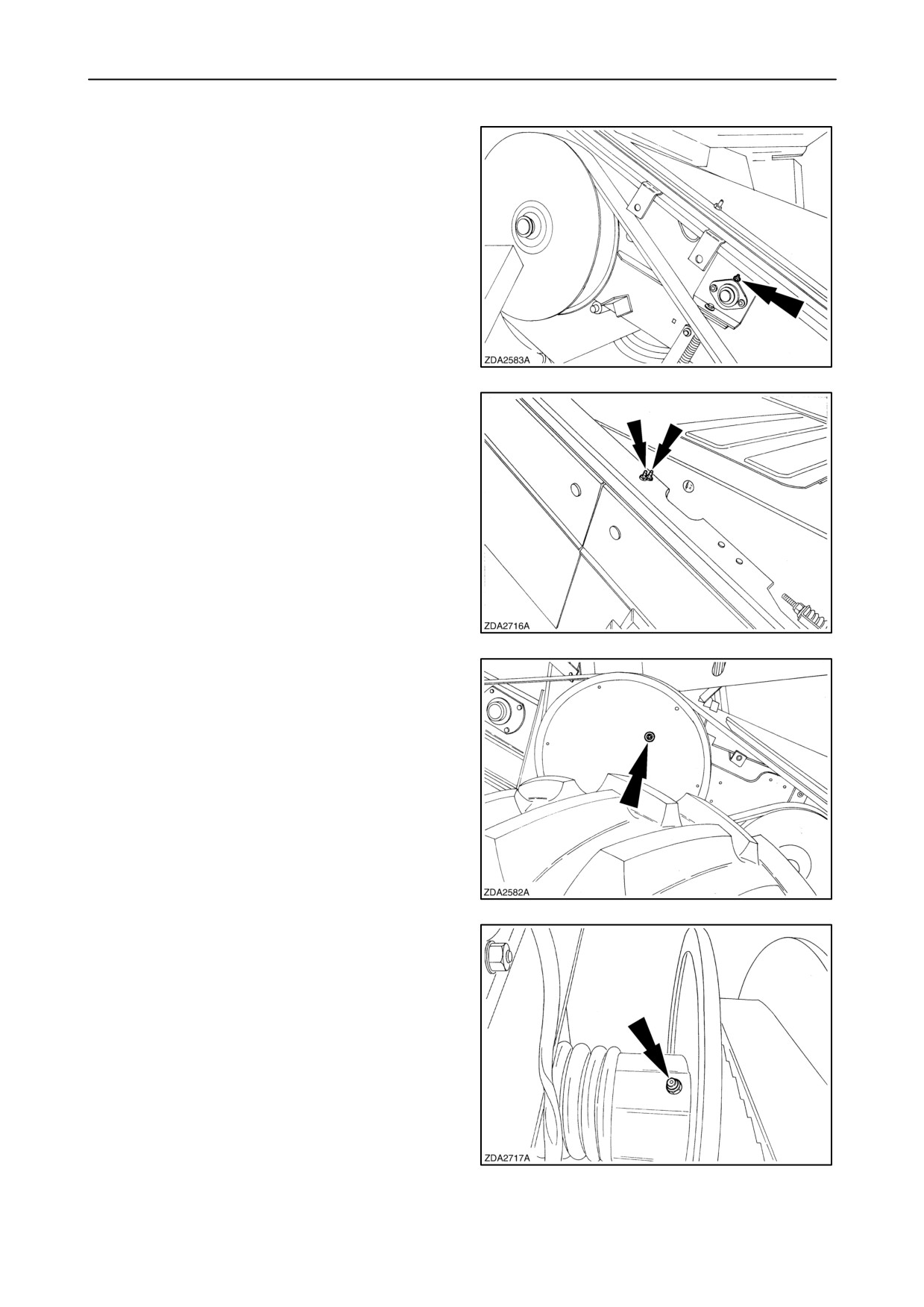
SECTION 4 - LUBRICATION AND MAINTENANCE
2. Straw elevator intermediate roll bearing
(If installed)
27
3. Straw elevator top shaft bearing
4. Straw elevator top shaft bearing housing
28
5. Slip clutch on straw elevator top shaft
29
6. Sliding sheave fan variator driven disc (3 x)
NOTE: Three grease zerks are installed to improve
access: Only one has to be greased.
30
4-9
SECTION 4 - LUBRICATION AND MAINTENANCE
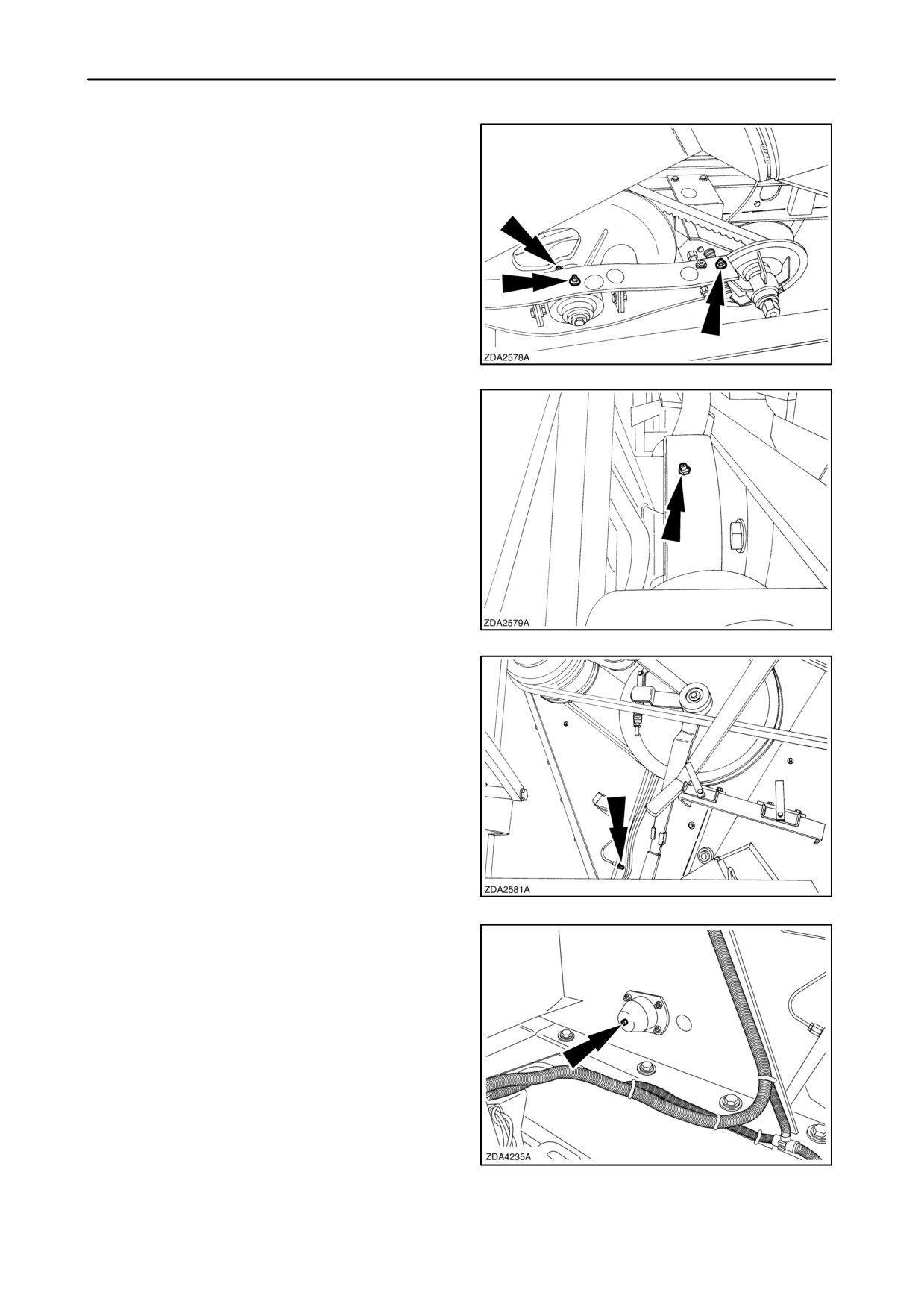
7. Thrust bearing on fan variation
8. Sliding sheave fan variator driver disc (3 x)
9. Hex. nut on fan variator control spindle
NOTE: After greasing, shift the variator from
minimum to maximum and vice versa to distribute the
grease in the hub.
31
10. Eccentric hub cleaning shoe drive
32
11. Straw flow beater shaft bearing
(intermediate shaft)
33
12. Straw walker front shaft bearing
34
4-10
SECTION 4 - LUBRICATION AND MAINTENANCE
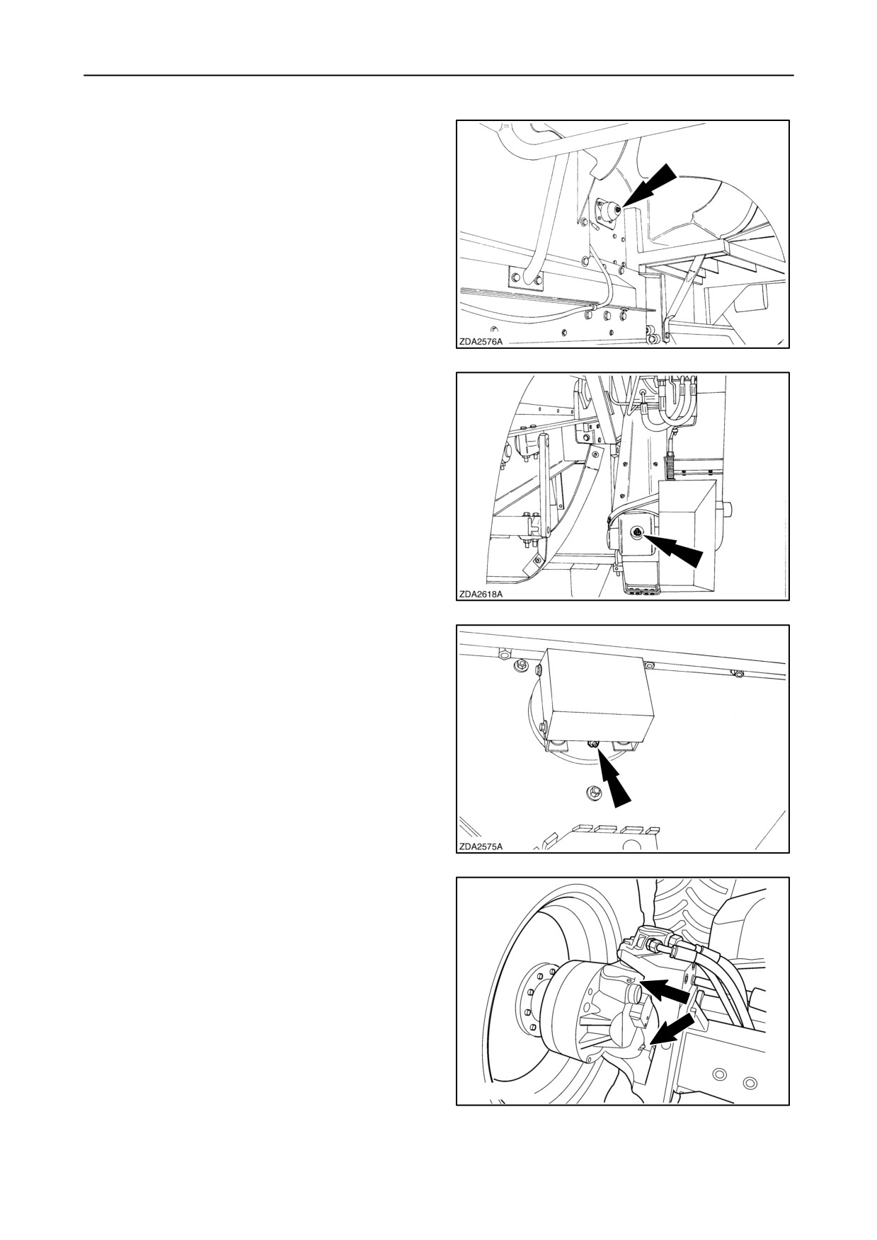
13. Straw walker rear shaft bearing
35
14. Returns gearbox (CX800 models)
36
15. Straw chopper rotor bearing
NOTE: Maximum 2 gun strokes every time the
bearing is greased.
37
16. Powered rear axle upper and lower king pin
bushings. (if installed)
20021843
38
4-11
SECTION 4 - LUBRICATION AND MAINTENANCE
100 hours interval - right-hand side
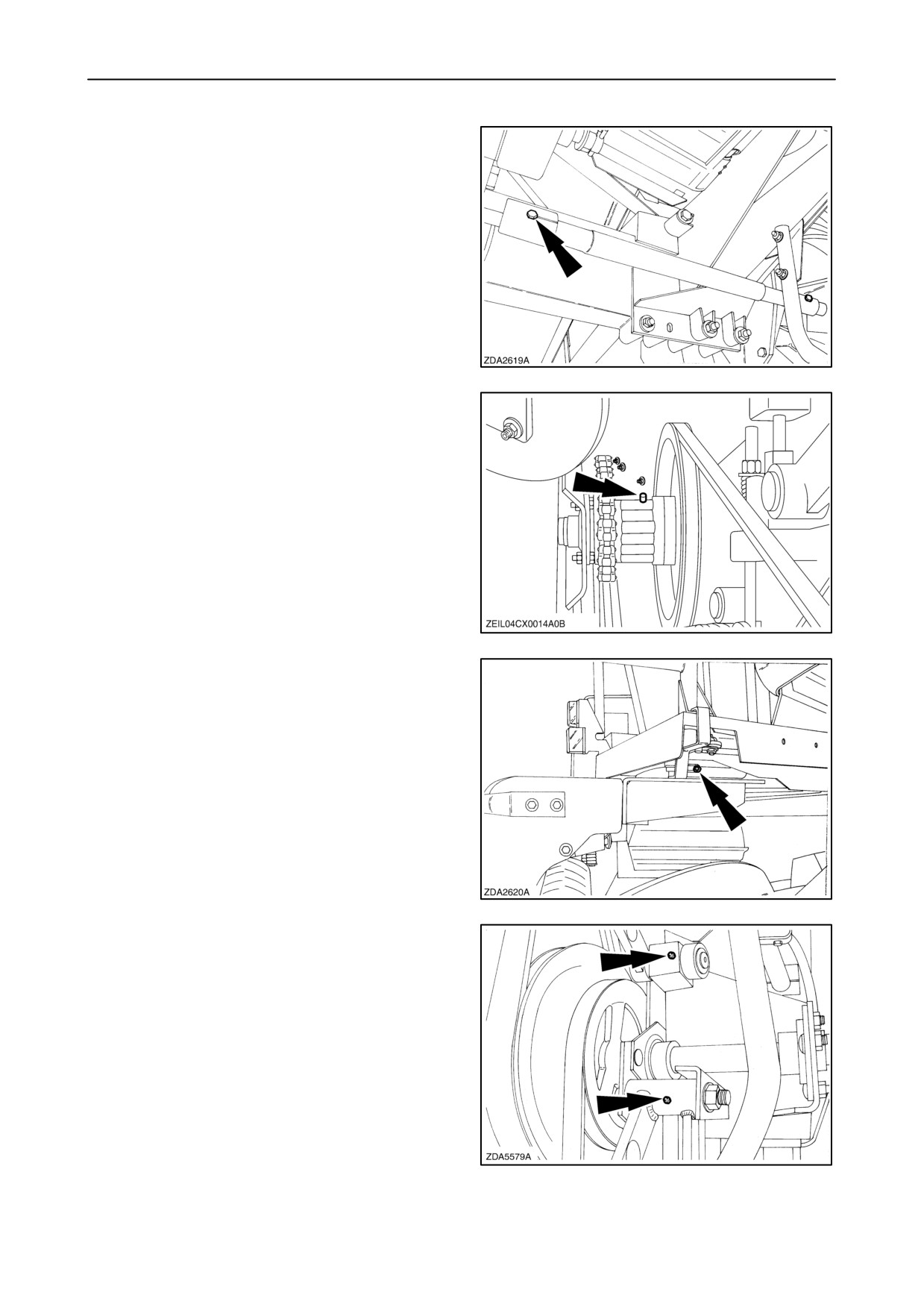
1. Half shaft couplers traction (2x)
39
2. Safety clutch on grain elevator
To easy reach the grease fitting, pull the idler
away and turn the V-pulley by hand.
NOTE: Maximum 2 gun strokes.
40
200 hours interval - left-hand side
1. Pivot ring platform ladder (2x)
41
2. Pivot point idler arm (2x)
(fixed cleaning shoe)
42
4-12
SECTION 4 - LUBRICATION AND MAINTENANCE
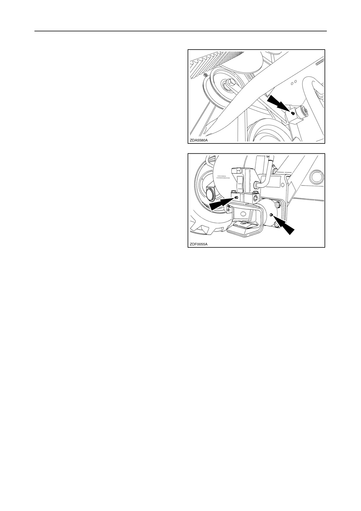
3. Pivot point idler arm
(self levelling cleaning shoe)
43
4. Automatic rotation trailer hitch (If installed)
44
4-13
SECTION 4 - LUBRICATION AND MAINTENANCE
ENGINE
Oil level
Check the engine oil level daily when the combine is
standing on a level surface and after the engine has
been stopped for a minimum of five minutes.
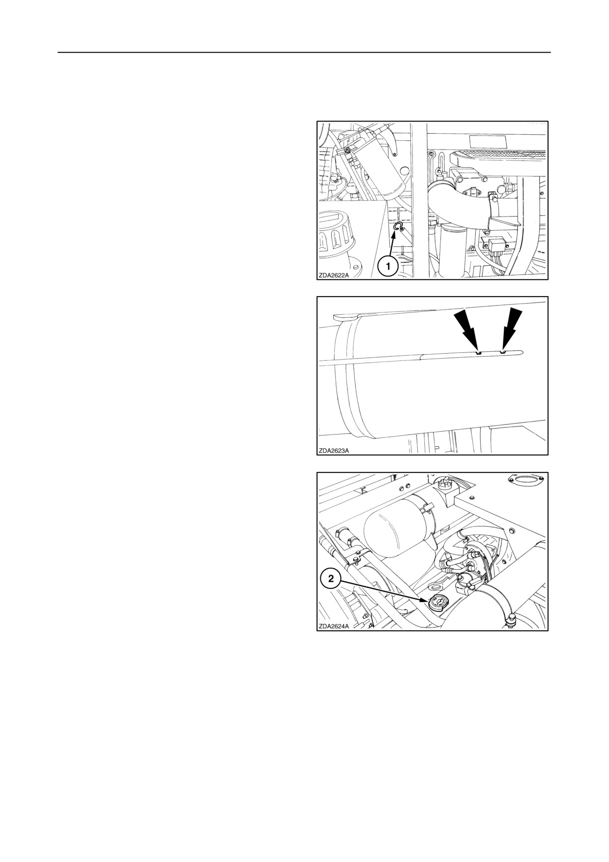
1. Remove the dipstick 1, wipe clean and re-insert
fully.
45
2. Pull the dipstick out again and check the oil level.
The oil level should be between the minimum and
the maximum mark.
IMPORTANT: At no time should the oil level be
allowed to fall below the minimum level.
46
If necessary, add oil through filler hole 2 until the oil
level reaches the maximum mark on dipstick.
IMPORTANT: Do not fill above upper mark on
dipstick. Excess oil will burn off, create smoke and
give a false impression of oil consumption.
47
4-14
SECTION 4 - LUBRICATION AND MAINTENANCE
Oil and filter change intervals
• CX720-740-760-780-820-840
(CNH engine)
After the first 100 operating hours.
NOTE: If necessary to add oil during the first 100
hours of operation, use oil specified in
‘‘Oil specifications’’ in this paragraph.
Every 300 operating hours or annually.
• CX860-880
(Iveco engine)
After the first 100 operating hours.
NOTE: If necessary to add oil during the first 100
hours of operation, use oil specified in
‘‘Oil specifications’’ in this paragraph.
Every 600 operating hours or annually.
The engine oil filter(s) should be changed every
time the oil is changed.
To change oil and filter, proceed as follows:
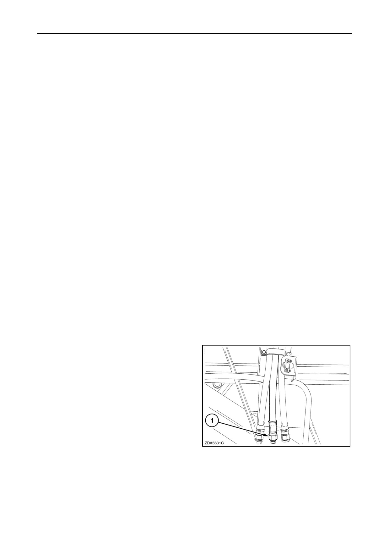
1. Warm the engine to operating temperature. Stop
the engine, drain the oil through hose 1 and catch
the oil in a suitable container.
48
4-15
SECTION 4 - LUBRICATION AND MAINTENANCE
2. The oil filter is accessible by removing the cover
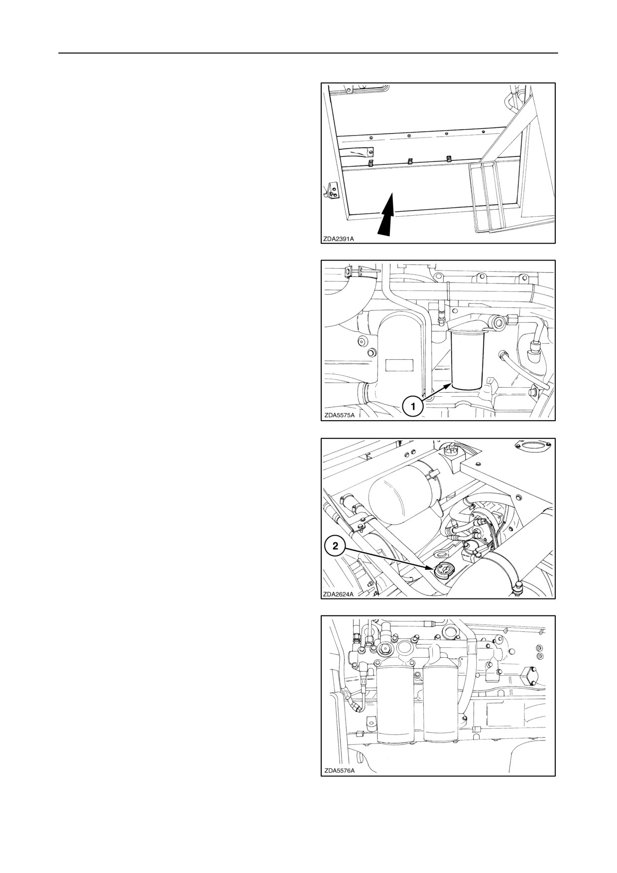
in the grain tank.
49
3. Clean the area round engine oil filter
1 and
remove the ”spin-on” filter using a filter wrench.
4. Fill up a new engine filter 1 with clean oil and apply
a film of oil to the seal ring.
5. Screw on the new filter by hand. Tighten firmly but
do not use tools.
6. Reinstall the plug of drain hose 1 (fig. 48).
50
7. Remove filler cap 2 and refill the engine with clean
oil. Re-install the filler cap.
8. Run the engine at low idle for a minute or so, to
circulate the oil, then stop the engine.
Check the oil filter for leaks.
9. Wait for a short period to allow the oil to drain back
to the sump. Check the oil level on dipstick as
explained in previous paragraph headed ”Oil
level”.
51
NOTE: CX880 is equipped with two engine oil filters.
52
4-16
SECTION 4 - LUBRICATION AND MAINTENANCE
Engine sump and filter capacity (total)
• CNH engine: 23 litres (6.08 US gal)
• Iveco engine:
- CX860 (F2B E0684 A*B002): 24 litres
(6.34 US gal); one oil filter.
- CX880 (F3A E0684 G*B003): 29 litres
(7.66 US gal); two oil filters.
Oil specification
Use AMBRA MASTER GOLD HSP, SAE15W40,
NH330H engine oil or an oil meeting the following
specification:
• API CH-4 or ACEA E3/E5
4-17
SECTION 4 - LUBRICATION AND MAINTENANCE
Crankcase breathing system (Iveco engine)
Replace the closed crankcase filter every
1500
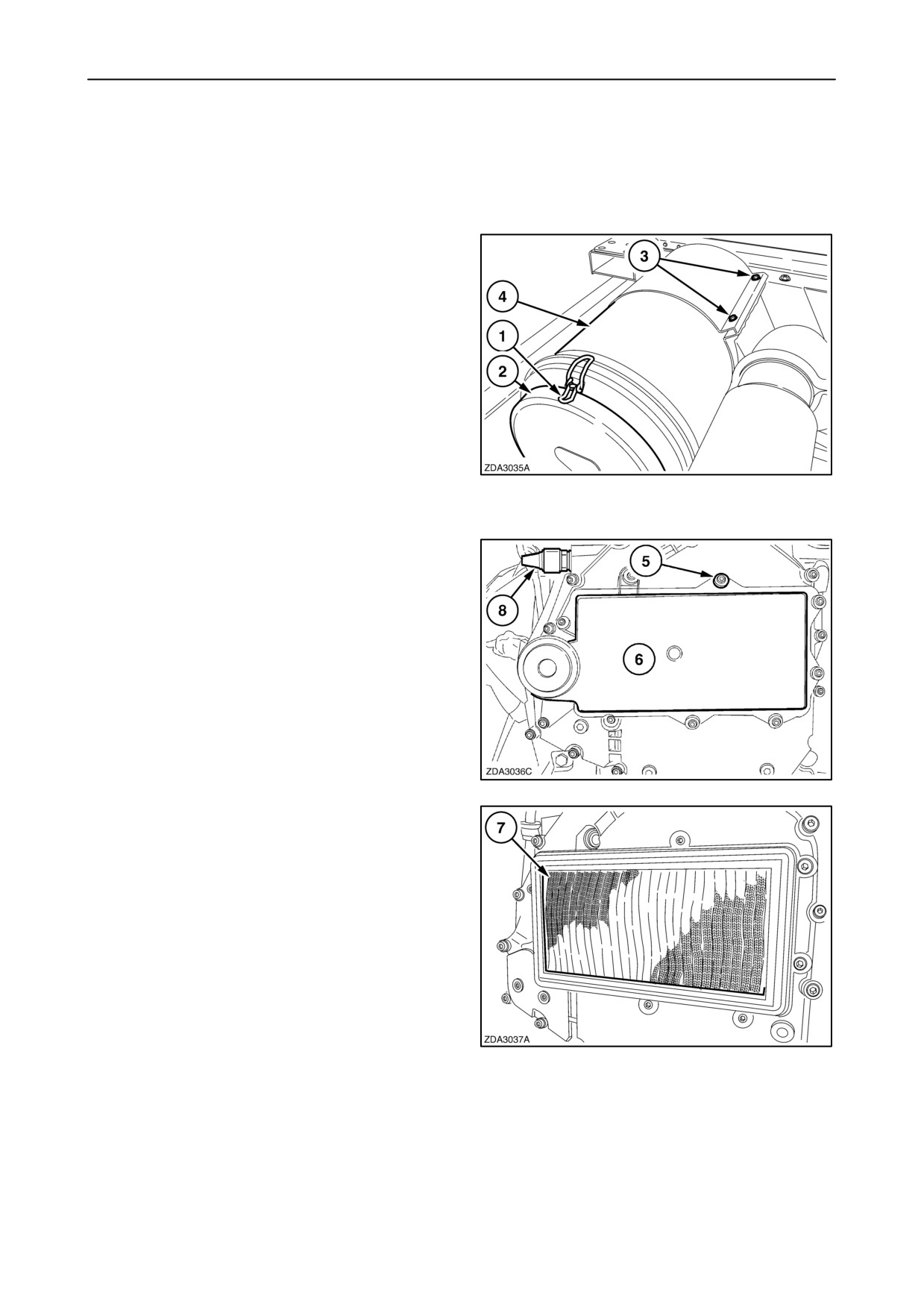
operating hours or if sight glass 8 shows a red pin
(see fig. 54)
To replace, proceed as follows:
1. Remove clamps 1 to remove cover 2.
2. Remove the filter element and the safety
element.
3. Loosen the two hose clamps of the hose to
disconnect the filter housing from the air channel
in the grain tank.
4. Loosen two bolts 3 to remove filter housing 4.
53
5. Remove nine bolts 5 to remove cover 6 of the
crankcase filter.
54
6. Replace crankcase filter 7.
55
4-18
SECTION 4 - LUBRICATION AND MAINTENANCE
7. Install cover 6 and tighten bolts 5.
8. Install filter housing 4 and tighten two bolts 3.
9. Install the two hose clamps of the hose to connect
the filter housing with the air channel in the grain
tank.
10. Install the safety element and the filter element.
11. Close the cover with the clamps 1.
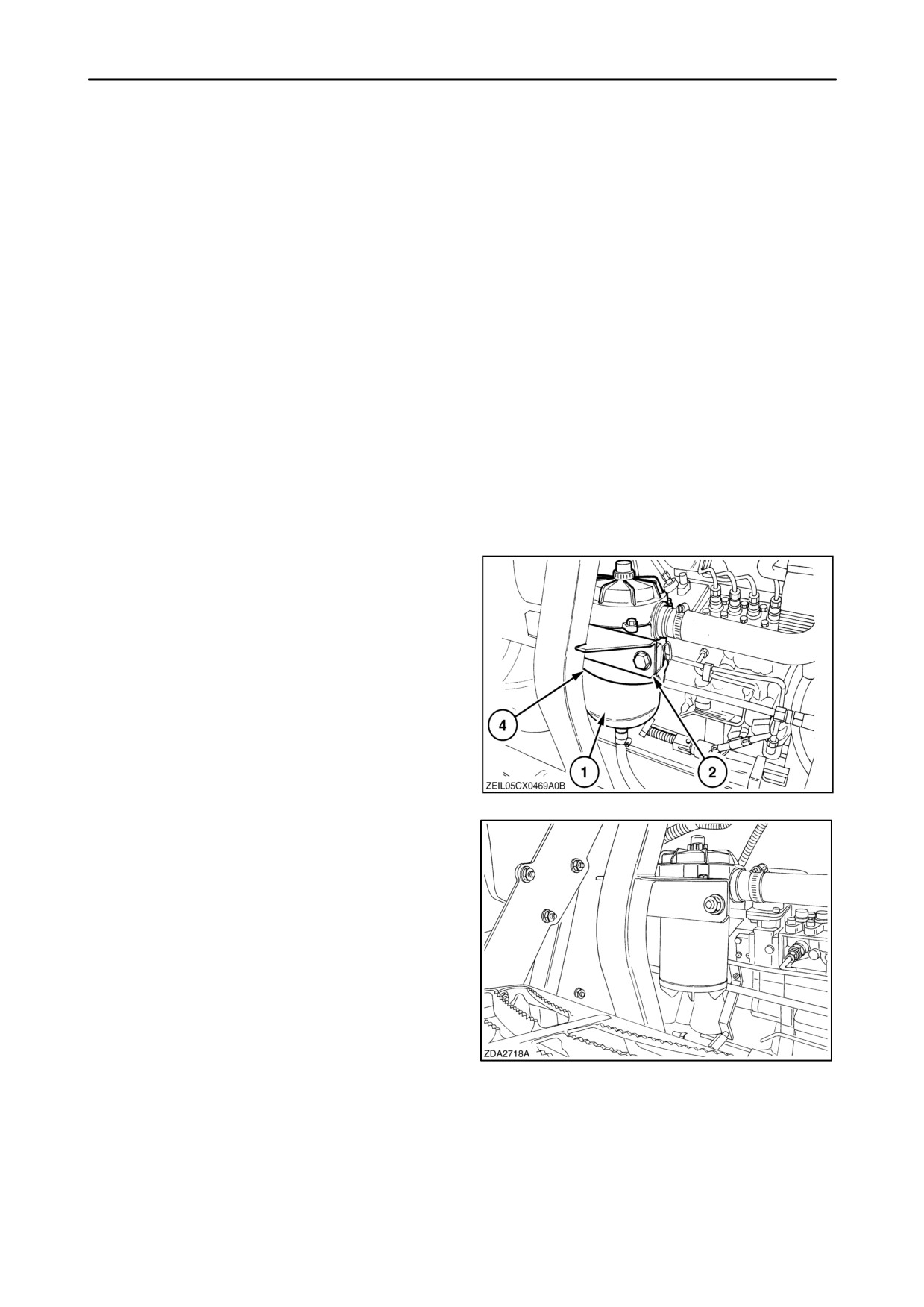
Crankcase breathing system (CNH engine)
The crankcase breathing system exists of two filters:
• Closed crankcase filter.
• Pre-separator on top of the engine.
To service the system, proceed as follows:
• Closed crankcase filter
Replace the filter every 600 operating hours or if the
sight glass shows a red pin.
To change proceed as follows:
1. Remove the wire (4).
2. Remove cover (1) by loosening clamps (2).
56
3. Remove the filter.
4. Clean any oil residue.
5. Install a new filter.
6. Install the cover with the clamps.
7. Install the wire.
57
4-19
SECTION 4 - LUBRICATION AND MAINTENANCE
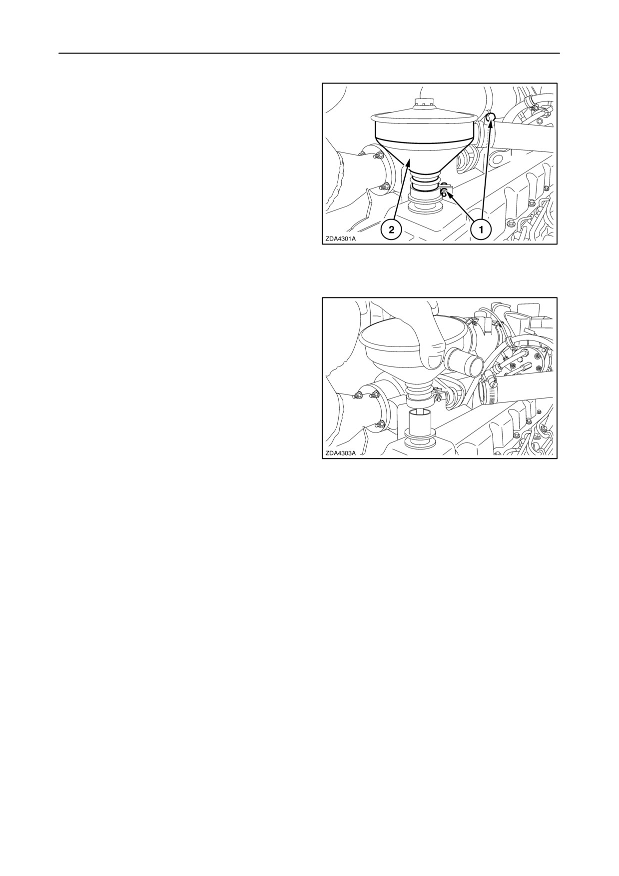
• Pre-separator
Clean the filter every 600 operating hours.
To clean, proceed as follows:
1. Loosen hose clamps 1 and remove filter 2.
58
2. Wash out the filter with kerosene and dry with
compressed air. Ensure no cleaning fluid remains
in the unit.
3. Install the filter and tighten the hose clamps.
59
Turbocharger compressor (CNH engine)
Clean turbocharger wheel and housing every 600
hours. To do this job, contact your local dealer.
Aftercooler (CNH engine)
Flush aftercooler every 600 hours or once a year,
whichever comes first. To do this job, contact your
local dealer.
4-20
SECTION 4 - LUBRICATION AND MAINTENANCE
ENGINE COOLING SYSTEM
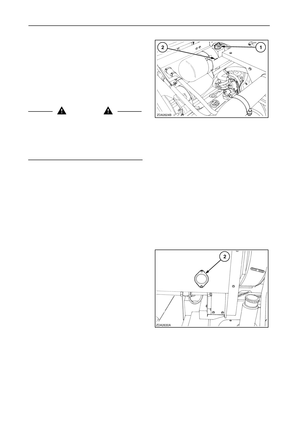
Coolant level
Check the coolant level daily in the shunt tank when
the engine is cold. The coolant level should reach
level indicator 2.
IMPORTANT: Under no circumstances should the
engine be started without coolant in the cooling
system.
WARNING
The cooling system operates under pressure which
60
is controlled by pressure/filler cap 1. Take care if
removing the pressure/filler cap while the system is
hot. Cover the cap using a thick cloth and open the
pressure/filler cap slowly and allow the pressure to
escape before removing the cap completely. Do not
add cold water to a hot shunt tank.
When the coolant level is too low, proceed as follows:
1. Run the engine at low idle.
2. Add coolant to the cooling system through shunt
tank filler opening 1. Never fill when the engine is
hot.
Coolant change
The coolant should be renewed:
• Every 2 years.
When replacing the coolant proceed as follows:
1. Remove cover 2.
61
4-21
SECTION 4 - LUBRICATION AND MAINTENANCE
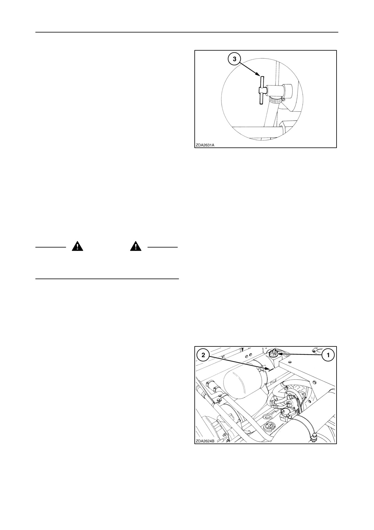
2. Drain the coolant by opening stopcock 3 at the
bottom of the radiator.
3. Flush the cooling system with clean water
(steps 3 to 6).
4. Close stopcock 3 and fill the cooling system with
clean water through shunt tank filler opening 1
(fig. 60).
5. Start the engine and run it at low idle until the
water temperature is at normal operating
temperature.
6. Stop the engine.
62
7. Drain the water by opening stopcock 3.
8. Close stopcock and fill the cooling system with
coolant as specified.
9. Install the cover.
IMPORTANT: Always fill the cooling system with an
approved antifreeze/water mixture. Check the
freezing point of the coolant after each refill.
CAUTION
The engine is hot and so may be the shunt tank.
Extreme care should be taken when filling the cooling
system.
10. Start the engine and run it at 1500 rpm until the
coolant temperature is at normal operating
temperature.
11. Return to low idle and stop the engine after 1
minute (Turbo charger precaution).
12. Fill the shunt tank to level indicator 2 and install
pressure/filler cap 1.
63
4-22
SECTION 4 - LUBRICATION AND MAINTENANCE
Coolant system capacity
• CNH engine: 40 litres (10.6 US gal)
• Iveco engine: CX860 = 46 litres (12.2 US gal)
CX880 = 50 litres (13.2 US gal)
Coolant specification
Use AGRIFLU antifreeze (ref. NH900A)
The coolant is a water/antifreeze mixture containing:
•
50% water
•
50% antifreeze: AGRIFLU (ref. NH900A)
The quality of the water should not exceed following
limits:
• Total hardness: 0.3%
• Chlorides: 0.1%
• Sulphates: 0.1%
FUEL SYSTEM
Fuel level
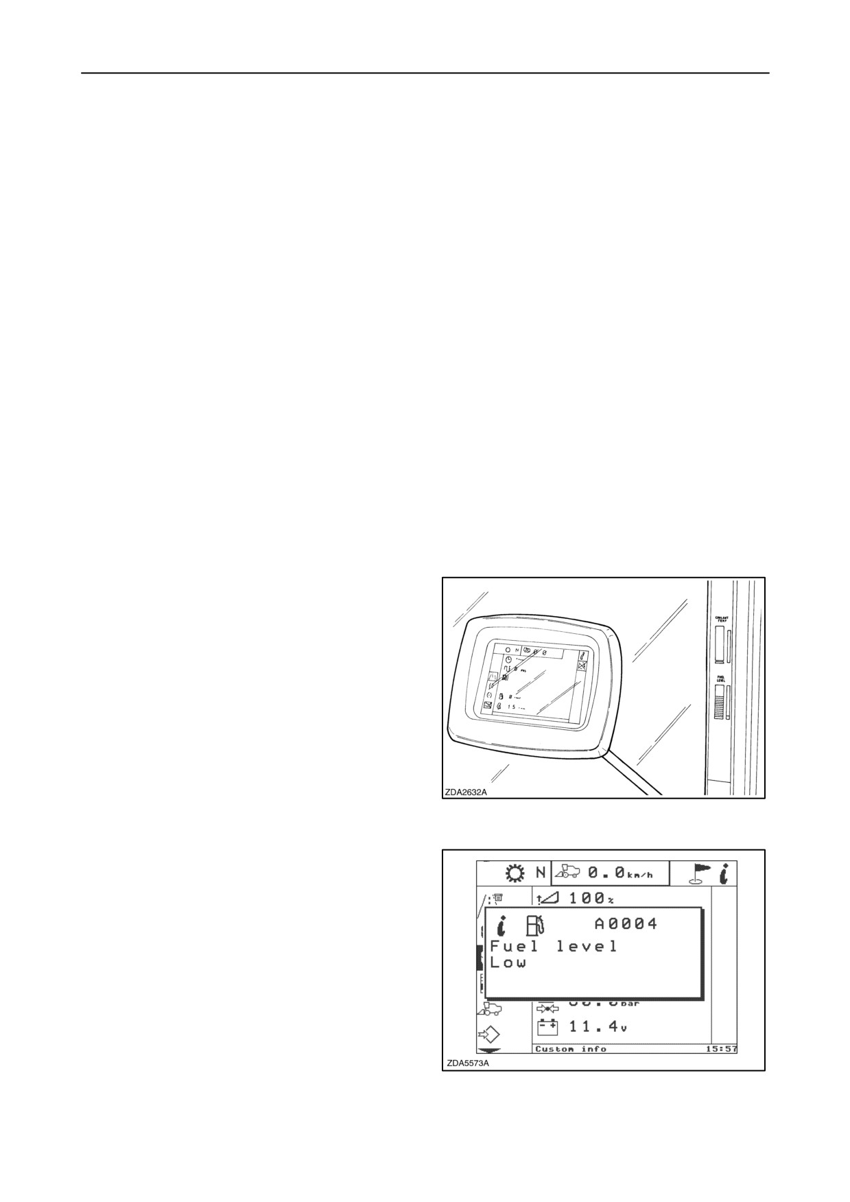
The fuel level can be checked on the bargraph
indicator integrated in the shaft speed monitor.
The fuel level can also be checked on the InfoViewt
monitor, in the diagnostics info screen.
64
When the fuel level is low level a pop-up screen
appears on the InfoViewt monitor.
65
4-23
SECTION 4 - LUBRICATION AND MAINTENANCE
Filling the fuel tank
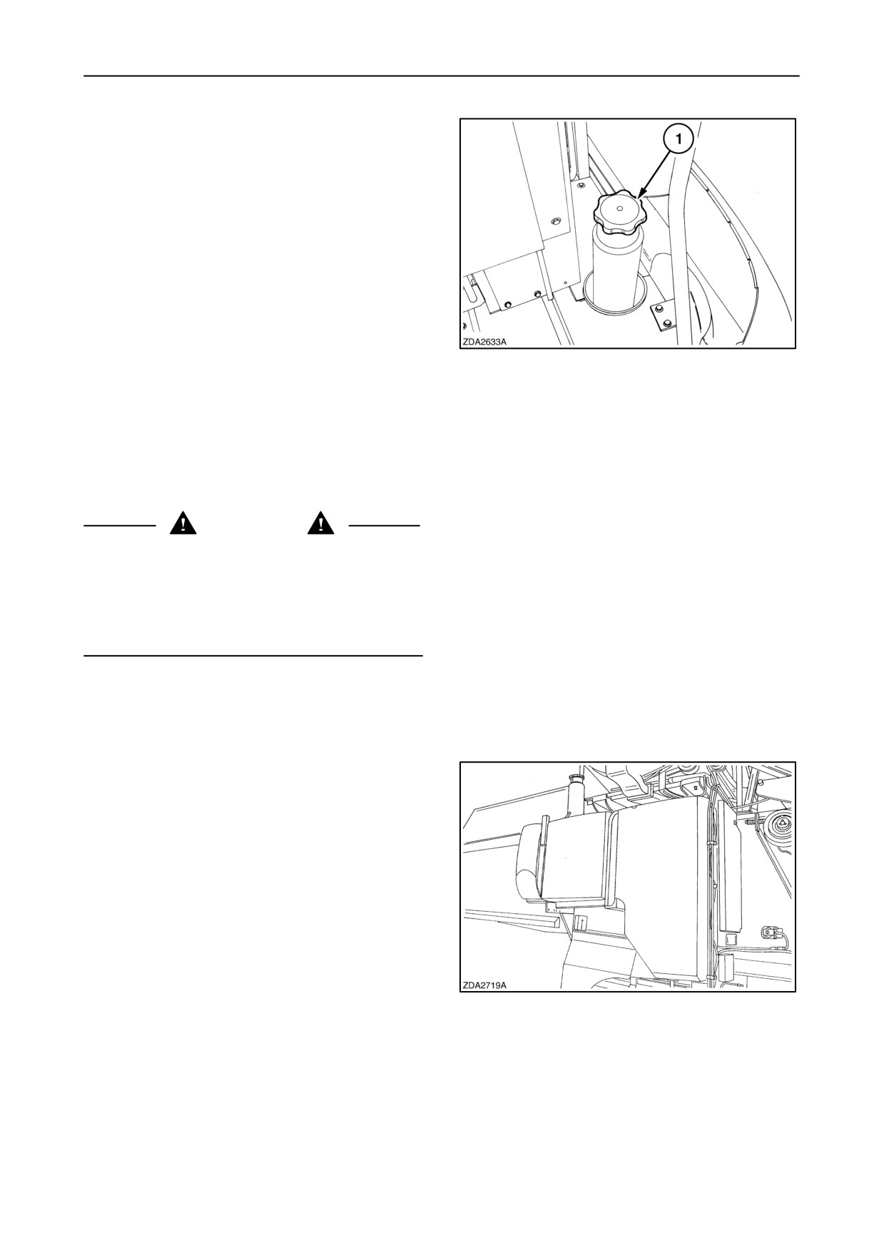
To fill the fuel tank, proceed as follows:
1. Stop the engine and wait until all rotating parts
have come to a complete standstill.
2. Before remove the fuel filler cap 1, clean the area
around the filler cap and the filler neck to prevent
dirt from entering the fuel tank and contaminating
the fuel.
3. Fill the fuel into the tank always trough a fine
gauze filter. Don’t fill the tank to capacity. Allow
room for expansion.
66
IMPORTANT: The best time to fill the tank is at the
end of the day to reduce overnight condensation.
IMPORTANT: If the original fuel tank cap is lost or a
new cap is required, replace it with a genuine original
vented cap.
CAUTION
When handling diesel fuel, observe the following:
• Smoking is strictly prohibited during filling the fuel
tank.
• Never fill the tank when the engine is running.
• Wipe up spilled fuel immediately.
Fuel tank capacity
Model CX720, 740, 760: 500 Litres (130 US gal)
Model CX780, 820, 840, 860, 880: 750 Litres
(200 US gal)
67
4-24

SECTION 4 - LUBRICATION AND MAINTENANCE
Fuel specification
The quality of fuel used is an important factor in
obtaining dependable performance and satisfactory
engine life.
Fuels must be clean, well-refined and non-corrosive
to fuel system parts. Be sure to use fuel of a known
quality from a reputable supplier.
To be sure that a fuel meets the required properties,
enlist the aid of a reputable fuel oil supplier. The
responsibility for clean fuel lies with the fuel supplier
as well as the fuel user
Use Number 2-D fuel in temperatures above -7_C
(20_F). Use of Number 2-D fuel at temperatures
below -7_C (20_F) will cause the fuel to thicken,
which may prevent the engine from running. (If this
happens, contact your dealer.)
Use Number 1-D fuel in temperatures below -7_C
(20_F).
Final
Cetane
Sulphur
General Fuel
Boiling
rating
content
Classification
Point
(min)
(max)
(max)
No. 1-D
288_C
40*
0.3%
(550_F)
No. 2-D
357_C
40*
0.5%
(675_F)
* When continually operating at low temperatures
or high altitude, a minimum cetane rating of 45 is
required.
Use fuel with a sulphur content below 0.5%. Using
fuel with a sulphur content above 0.5% requires more
frequent oil changes as noted in the maintenance
schedule. The use of diesel fuel with a sulphur
content above 1.3% is not recommended.
NOTE: Bio fuel is accepted for maximum 5%
4-25
SECTION 4 - LUBRICATION AND MAINTENANCE
Fuel storage
Many engine difficulties can be traced to dirty fuel,
therefore the importance of using clean fuel, properly
stored cannot be stressed too strongly.
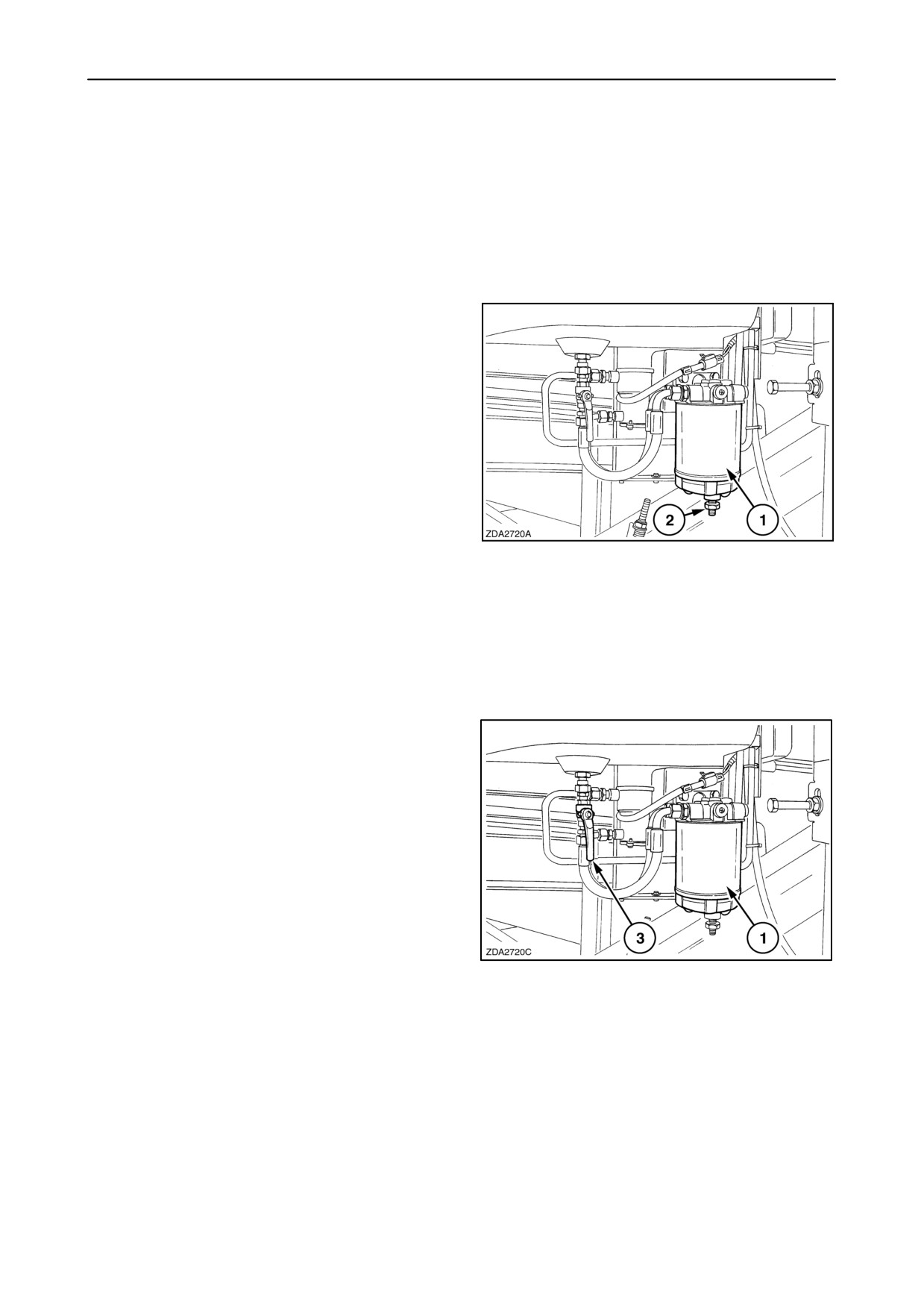
Fuel prefilter/water separator
Drain the water from prefilter/water separator (1)
daily, proceed as follows:
1. Loosen the screw (2) to allow the water to run out
of the screw orifice.
2. Collect the water/fuel mixture and dispose
according to regulations.
3. Tighten the screw (2) when fuel free of water runs
out of the screw orifice.
68
The fuel prefilter/ water separator
(1) should be
changed every 600 operating hours, or earlier, if a
drop in engine performance is experienced.
To change the prefilter/water separator, proceed as
follows:
1. Wipe the top of the prefilter/water separator head
clean.
2. Turn the fuel valve (3) to the closed position.
3. Unscrew the ”spin-on” prefilter/water separator
(1), using a filter wrench.
4. Fill the new prefilter/water separator
(1) with
clean fuel and apply a film of fuel to the gasket.
5. Screw on the new prefilter/water separator by
hand. Tighten firmly, but do not use tools.
6. Turn fuel valve (3) to the open position.
7. Bleed the fuel system (refer to paragraph headed
”Bleeding the fuel system”).
69
4-26
SECTION 4 - LUBRICATION AND MAINTENANCE
Fuel filter (CNH engine)
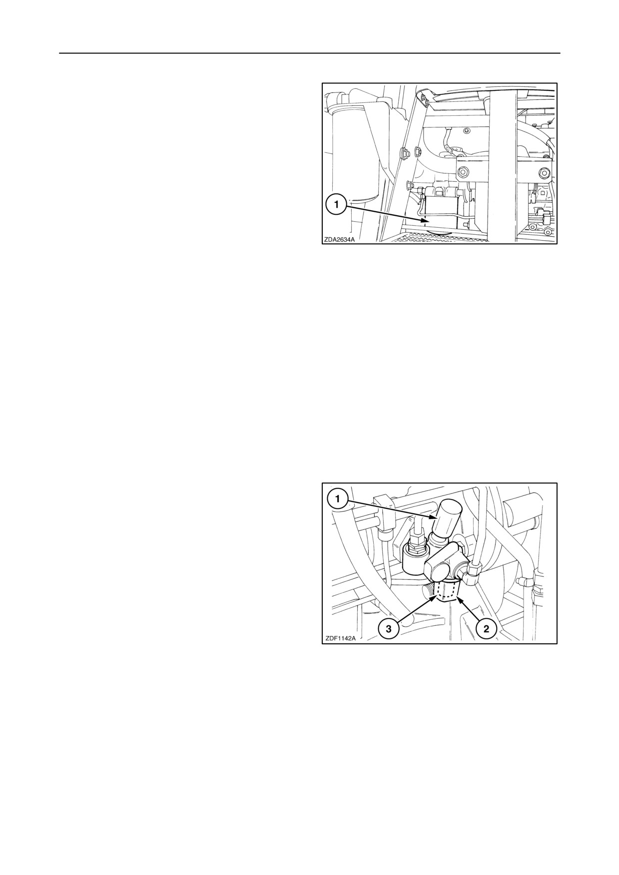
The fuel filter
1 should be changed every 600
operating hours. Proceed as follows:
1. Wipe the top of the filter head clean.
2. Loosen the screw at the bottom of filter 1 to allow
the fuel to run out of the screw orifice.
3. Unscrew the fuel filter, using a filter wrench.
70
4. Coat a film of fuel to the seal of the new fuel filter.
5. Screw the new filter on by hand and tighten it
securely (firmly against the head and then an
additional 1/4 to 1/2 turn). DO NOT USE TOOLS.
6. Close the screw at the bottom of the filter.
7. Bleed the fuel system, refer to next paragraph
headed: ”Bleeding the fuel system
(CNH engine)”.
8. The fuel filter contains a sediment bowl at its
bottom side, which collects large particles of dirt
and water. This sediment bowl can be removed
and cleaned.
Fuel supply pump
A fuel supply pump is also fitted to at the entry point
into the injection pump fuel system. The purpose of
the supply pump is to draw fuel from the tank, and
pressurize the fuel to a minimum of 1.4 bar (20 psi)
in order to cause fuel to flow through the filter and to
provide sufficient pressure for pumping element fill-
ing. The supply pump housing also contains a sedim-
enter assembly consisting of a clear bowl (2) and
strainer screen (3). The clear bowl should be in-
spected for sediment every 50 hours and cleaned
every 600 hours.
71
On top of the supply pump is fitted a primer pump (1)
which is used to prime the injection pump with fuel
when the filter element has been changed.
4-27
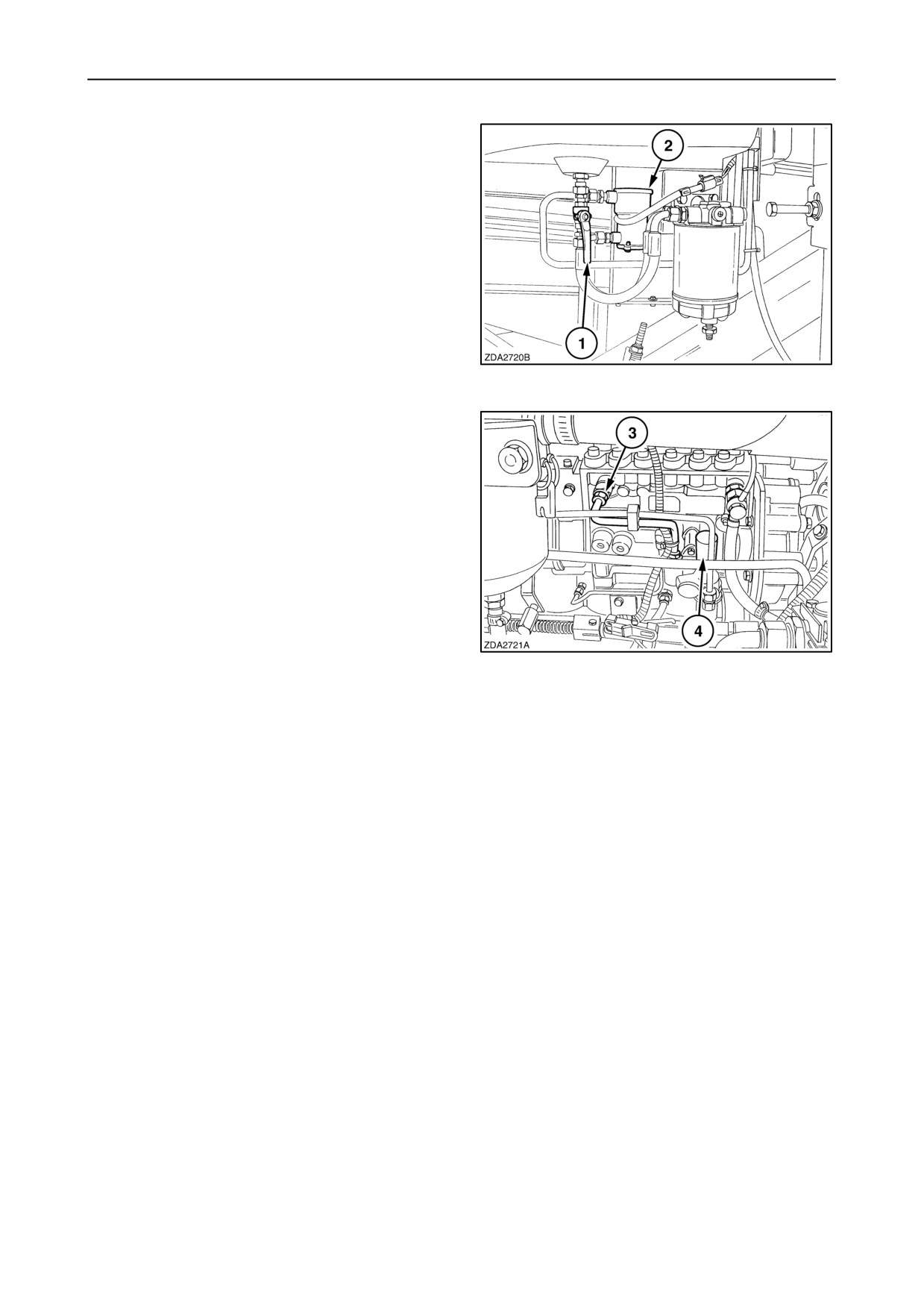
SECTION 4 - LUBRICATION AND MAINTENANCE
Bleeding the fuel system (CNH engine)
To bleed the fuel system, proceed as follows:
1. Ensure there is fuel in the fuel tank and tap 1 is
open.
2. Set the ignition switch in the ”contact” position to
engage electrical fuel pump 2.
72
3. Loosen fuel line 3 at the injection pump.
4. Operate fuel lift pomp piston 4 by hand until the
fuel escaping is free from air bubbles.
5. Retighten fuel line 3 when fuel free of air bubbles
escapes.
6. Continue pumping until the force needed remains
more or less constant. This allows the fuel to be
drawn into the injection pump.
7. Start the engine.
73
8. Run the engine at low idle until the engine runs
smoothly.
4-28
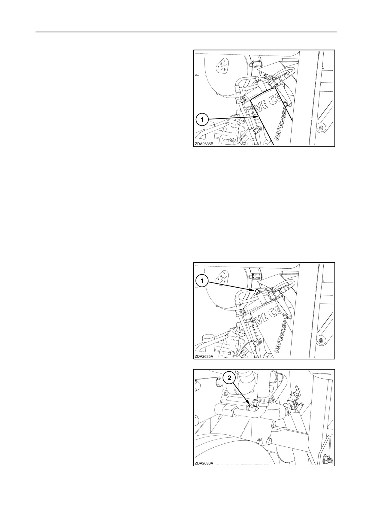
SECTION 4 - LUBRICATION AND MAINTENANCE
Fuel filter (Iveco engine)
The fuel filter
1 should be changed every 600
operating hours. Proceed as follows:
1. Wipe the top of the filter head clean.
2. Unscrew the fuel filter, using a filter wrench.
3. Coat a film of fuel to the seal of the new fuel filter.
4. Screw the new filter on by hand and tighten it
securely (firmly against the head and then an
additional 1/4 to 1/2 turn) DO NOT USE TOOLS.
74
5. Bleed the fuel system, refer to next paragraph
headed ”Bleeding the fuel system”
(Iveco engine).
Bleeding the fuel system (Iveco engine)
To bleed the fuel system, proceed as follows:
1. Ensure there is fuel in the fuel tank and the tap is
open.
2. Set the ignition switch in the ”contact” position to
engage the electrical fuel pump.
3. Loosen bleed screw 1 to allow the air to escape.
4. Tighten the bleed screw when fuel free of air
bubbles escapes.
75
5. Loosen bleed screw 2 to allow the air to escape.
NOTE: To avoid possible fuel contamination, install
a transparent housing onto the bleed screw, to catch
the fuel in a suitable container and also to check if the
fuel escaping from the bleed screw is free of air
bubbles.
6. Tighten the bleed screw when fuel free of air
bubbles escapes.
7. Start the engine.
8. Run the engine at low idle until the engine runs
smoothly.
76
4-29
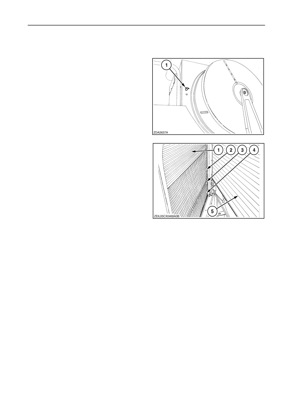
SECTION 4 - LUBRICATION AND MAINTENANCE
ROTARY DUST SCREEN AND COOLING SYSTEM
The CX models are equipped with a hinged rotary
dust screen door.
To gain access to clean the cooling system, proceed
as follows:
Open the rotary dust screen door with key 1.
77
Clean the cooling system regularly, depending on
combining conditions.
• Intercooler 1
• Watercooler 2
• Gearbox oil cooler 3
• Hydrostatic oil cooler 4
78
• Air-conditioning condenser 5
4-30
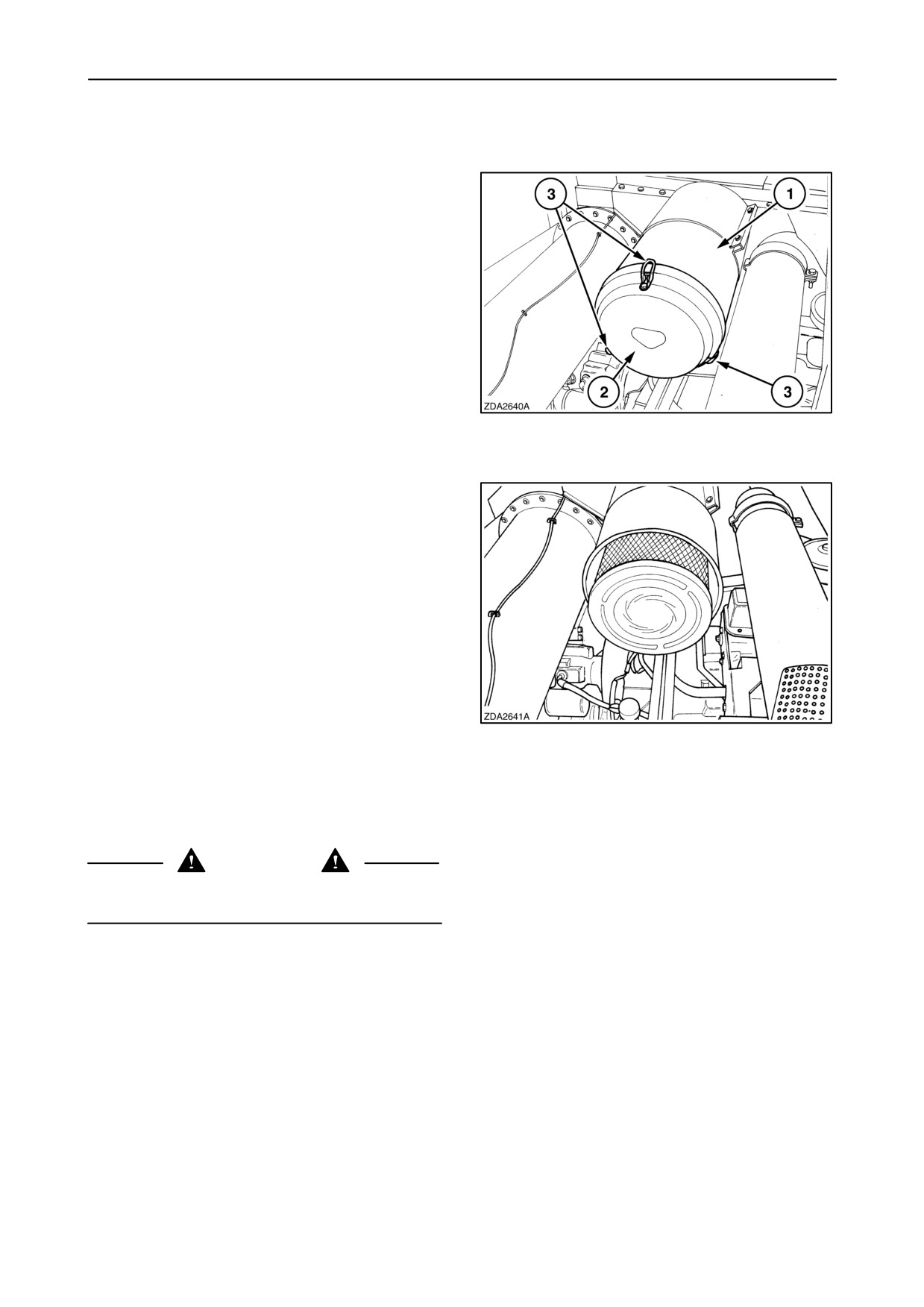
SECTION 4 - LUBRICATION AND MAINTENANCE
AIR INTAKE SYSTEM
The air filter element 1 should only be cleaned when
there is an alarm on the InfoViewt monitor
”Air filter blocked” (625 mm) (24 - 5/8”) vacuum.
To remove the air filter element, remove cover 2 by
loosening clamps 3.
To clean the element, hold the top and tap it against
the palm of the other hand to remove the dust.
NEVER TAP IT ON A HARD SURFACE.
79
When tapping does not remove the dirt, direct
compressed air through the element, from the inside
towards the outside.
To prevent damage to the element when cleaning
with compressed air, take the following precautions:
• Maximum air pressure must be 5 bar (72,5 psi).
• Move the nozzle up and down when rotating the
element.
• Keep the nozzle at least 25 mm (1”) from the
plated paper.
80
NOTE: To keep the interval acceptable is it highly
recommended to clean the element with compressed
air.
WARNING
Wear a dust mask when cleaning the air filter
element.
If the element is soiled with oil or soot, it is possible
to soak it for 15 minutes in a solution of 75 grammes
(0,165 lbs.) of non-sudsy detergent and 10 litres
(2,6 US gal) of lukewarm water.
Rinse the element thoroughly in clean water until the
water remains clear and leave the element to dry.
NEVER WASH THE AIR FILTER ELEMENT IN
PETROL OR DIESEL OIL.
4-31
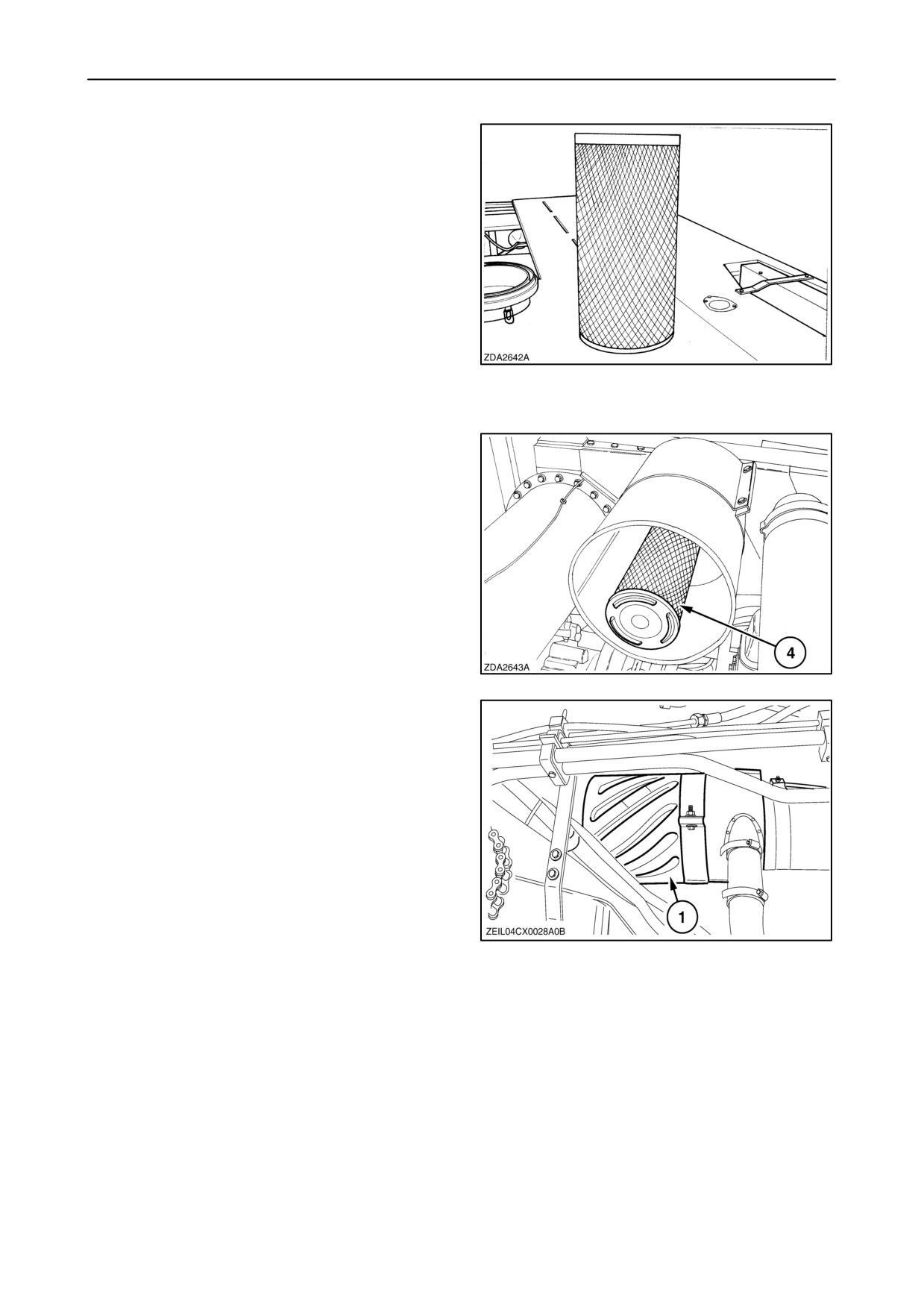
SECTION 4 - LUBRICATION AND MAINTENANCE
Every time the element is cleaned, it should be
examined for holes and cracks by holding an electric
light bulb inside the element and looking through it.
If any damage is noted, discard the element and fit a
new one.
Replace the element after 10 cleanings or once a
year, whichever comes first.
When fitting, make sure the element is seated
properly and the sealing is in good condition.
81
A safety element 4 is fitted as an additional security
to prevent dust from entering the engine when
replacing the standard element. The safety element
should normally not be cleaned.
Replace the safety element every two years.
82
A pre air filter is located near the grain tank under the
unloading tube.
No maintenance is required.
83
4-32
SECTION 4 - LUBRICATION AND MAINTENANCE
HYDRAULIC AND HYDROSTATIC SYSTEM
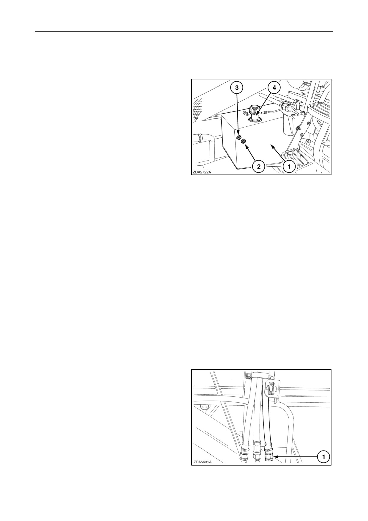
Oil reservoir
A single oil reservoir 1 is fitted for the hydraulic and
hydrostatic system. Both systems draw their oil from
the same reservoir but the oil for each circuit goes
through a separate filtering system.
Oil level
Ensure that all hydraulic cylinders are retracted
before checking the oil level.
Check the oil level daily on sight glasses 2 and 3. The
oil level should minimum reach bottom sight glass 2.
If necessary, add oil through filler opening 4.
84
IMPORTANT: Always clean the reservoir filler cap
and the surrounding area before removing the filler
cap to top-up or replace the oil.
Oil and filter change
The hydraulic/hydrostatic oil and filters should be
changed:
• Only filters after the first 100 operating hours.
• Thereafter, every 600 operating hours or annually
The hydraulic return filter and the hydrostatic
charge-pressure filter need to be replaced at every oil
change.
The hydraulic high pressure filter and the oil reservoir
filter need to be cleaned at every oil change.
To change the oil and/or filters proceed as follows:
1. Thoroughly clean the surrounding area of the
reservoir and filters
(with compressed air, if
possible).
2. Retract all hydraulic cylinders.
3. Drain the oil from the reservoir through hose 1
and catch the oil in a suitable container.
85
4-33
SECTION 4 - LUBRICATION AND MAINTENANCE
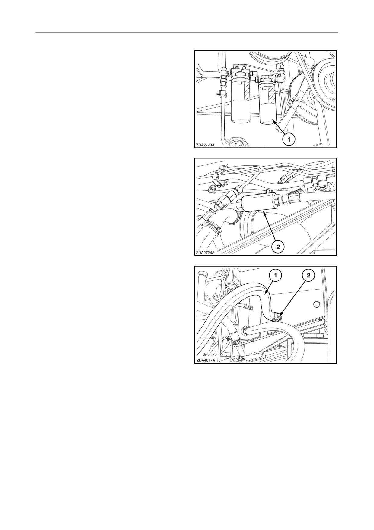
4. Remove the hydraulic return filter 1.
5. Apply a film of oil to the gasket of the new filter.
6. Screw on the new filter by hand. Tighten firmly but
do not use tools.
NOTE: The hydraulic return filter 1 can be changed
without drain the oil.
86
7. Remove hydraulic charge-pressure filter 2.
8. Wash the filter or clean the filter with compressed
air.
9. Re-install the filter.
87
10. Loosen hose 1 and remove the hydraulic hose at
the oil reservoir filter.
11. Screw filter 2 out.
12. Wash or clean the filter with compressed air.
13. Re-install and tighten the filter 2.
Aluminium filter: maximum torque 90 Nm
(66 ft.lbs)
Metal filter: maximum torque 170 Nm
(125 ft.lbs)
88
14. Install and tighten the hydraulic hose 1 onto the
filter.
Aluminium filter: maximum torque 140 Nm
(103 ft.lbs)
Metal filter: maximum torque 255 Nm
(188 ft.lbs)
4-34
SECTION 4 - LUBRICATION AND MAINTENANCE
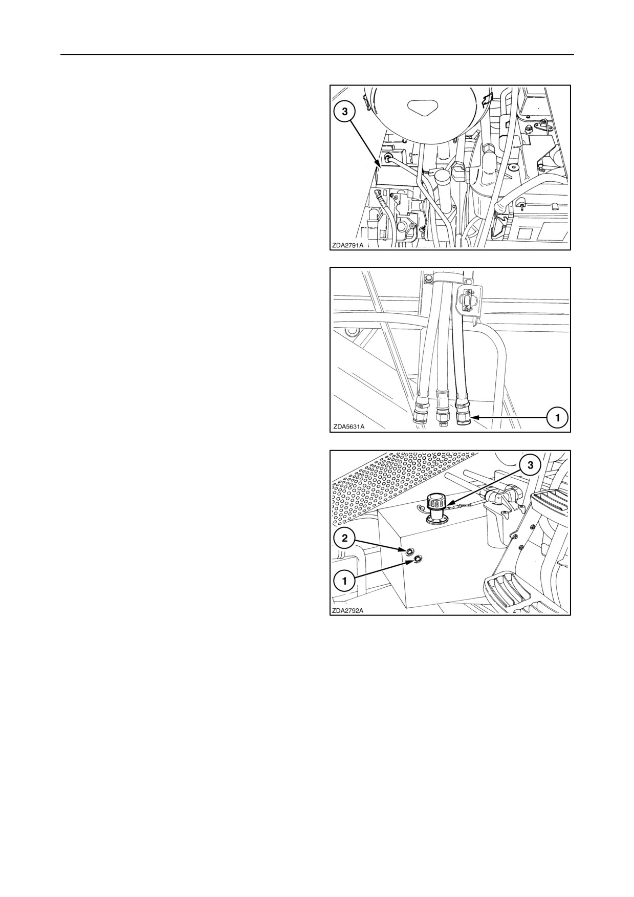
15. Remove the hydrostatic charge-pressure filter 3.
16. Apply a film of oil to the gasket of a new
hydrostatic charge-pressure filter.
17. Screw on the new filter by hand. Tighten firmly but
do not use tools.
89
18. Reinstall the plug of drain hose 1.
90
19. Fill the reservoir through filler hole
3 to the
maximum on the oil level gauge 2.
20. Start the engine. Run it at idle speed for five
minutes and move the ground speed control lever
slowly forward and backward with the gearshift in
neutral position and the rear wheel drive
(if installed) disengaged.
21. Check the oil level on the sight glasses.
The oil level should minimum reach bottom sight
glass 1.
91
4-35
SECTION 4 - LUBRICATION AND MAINTENANCE
Oil capacity
Reservoir capacity: 50 litres (13 US gallons)
Entire system capacity: 70 litres (18.5 US gallons)
Oil specification
Use AMBRA HYDROSYSTEM 46 HV (NH646H)
hydraulic/ hydrostatic oil or an oil meeting the
following specification:
• DIN 51524 PART 2 HV46
• ISO VG-46
or
Use AMBRA MULTI G, NH410B or an oil meeting the
following specification:
• M2C 134-D
The hydraulic/ hydrostatic system is factory-filled
with AMBRA HYDROSYSTEM 46 HV, NH646H
hydraulic oil.
This is an oil with a high viscosity index, which means
that the oil remains fluid at low temperatures.
IMPORTANT: Oil quality and cleanliness is of utmost
importance for the reliability and life of the hydraulic
and hydrostatic system. Deviation of the prescribed
oil specification may lead to severe damage and void
warranty.
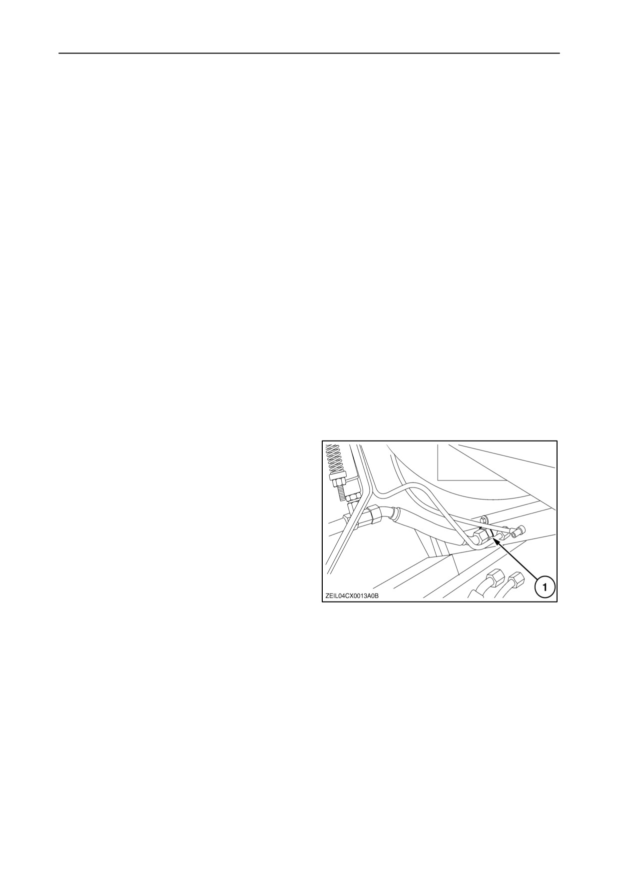
Filter at oil cooler outlet
A filter element (1) is installed at the oil cooler outlet,
to prevent contamination in the hydrostatic system
after start up.
92
4-36
SECTION 4 - LUBRICATION AND MAINTENANCE
ENGINE GEARBOX
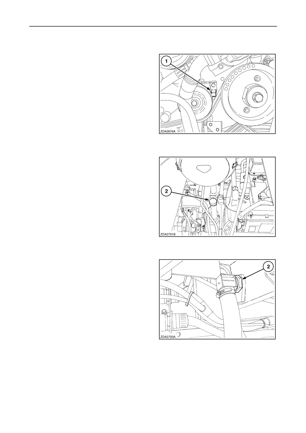
Oil level
Check the oil level daily on level gauge 1 with the
combine standing on a level surface. The oil level
should be kept between the marks.
93
If necessary, remove filler cap 2 and add oil through
the filler opening.
94
Oil and filter change
The engine gearbox oil should be changed:
• Only filter after the first 100 operating hours
• Thereafter, every 600 operating hours or annually
The oil filter should be changed every time the oil is
changed.
The suction screen 2 (installed in suction opening)
should be washed every time the oil is changed.
95
4-37