New Holland CX720, CX740, CX760, CX780, CX820, CX840, CX860, CX880. Operator's Manual - page 9
SECTION 3 - FIELD AND SITE OPERATION
Grain tank unloading auger
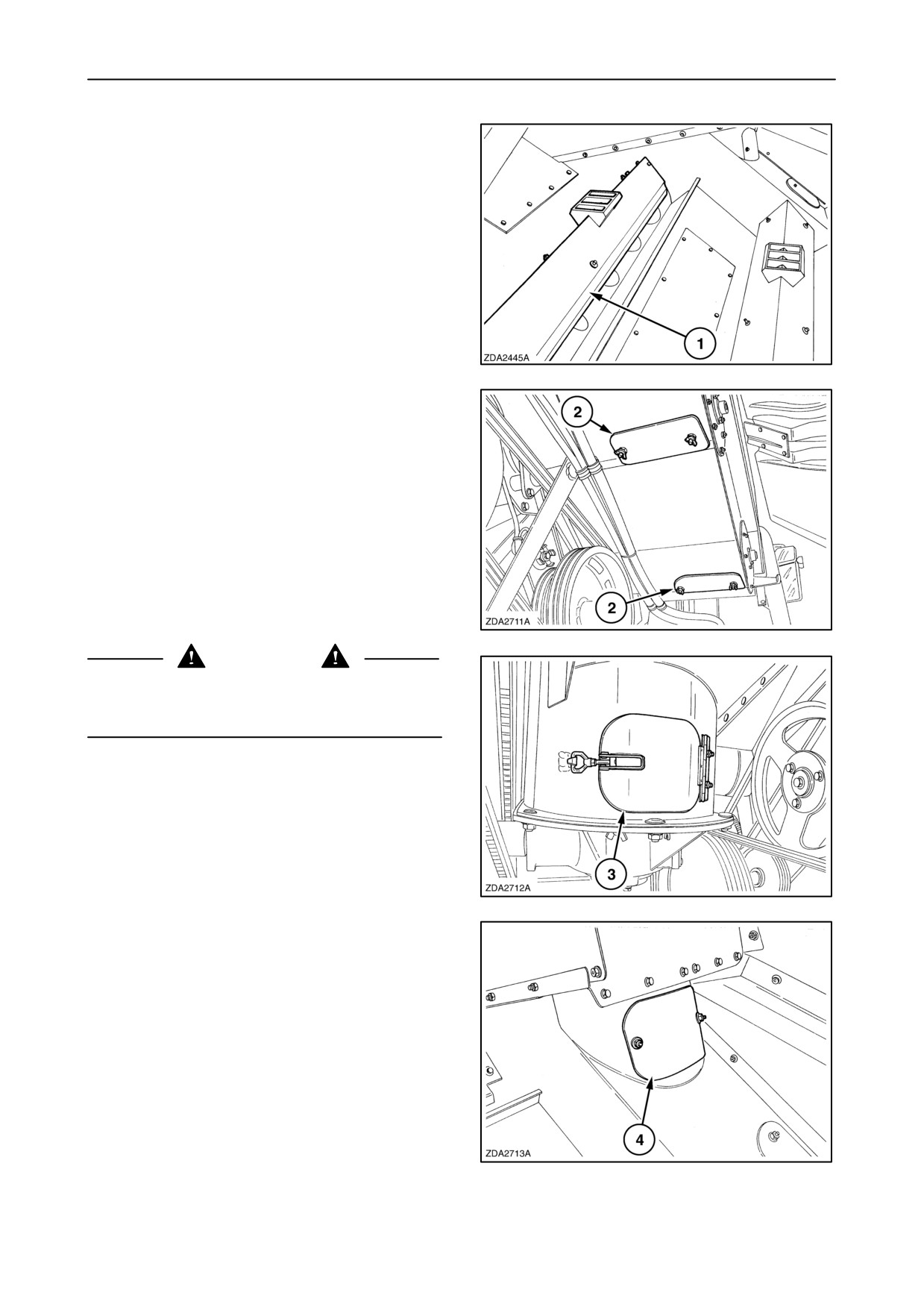
Cover plates are fitted over both grain tank unloading
augers. These cover plates are fitted with plates 1
which can be adjusted to regulate the unloading rate
according to the nature and moisture content of the
grain being handled.
Raise the plates to increase the unloading rate and
lower them to reduce it.
145
To clean the grain tank open both unloading auger
covers 2.
146
WARNING
Always disengage the unloading auger drive, turn off
the engine and remove the ignition key, before
removing the auger access cover.
To clean the vertical auger of the unloading tube open
cover 3.
147
To check or clean the vertical auger of the unloading
tube open the inspection cover 4.
148
3-80
SECTION 3 - FIELD AND SITE OPERATION
Unloading tube swing
A warning light is provided in the cab (SSM) to warn
the operator when the unloading tube is not in the fully
closed position as this may be an operating hazard in
fields with trees, high tension wire pylons, telegraph
poles, etc.
NOTE: Wait 5 seconds to swing out the unloading
tube, after starting up the engine.
Unloading mechanism
To engage the unloading mechanism press the
unload engagement button (first time) on the multi
function handle.
To disengage press again the unload button (second
time) or:
• Depress the emergency stop button.
• Select the road mode with the road mode selector
switch.
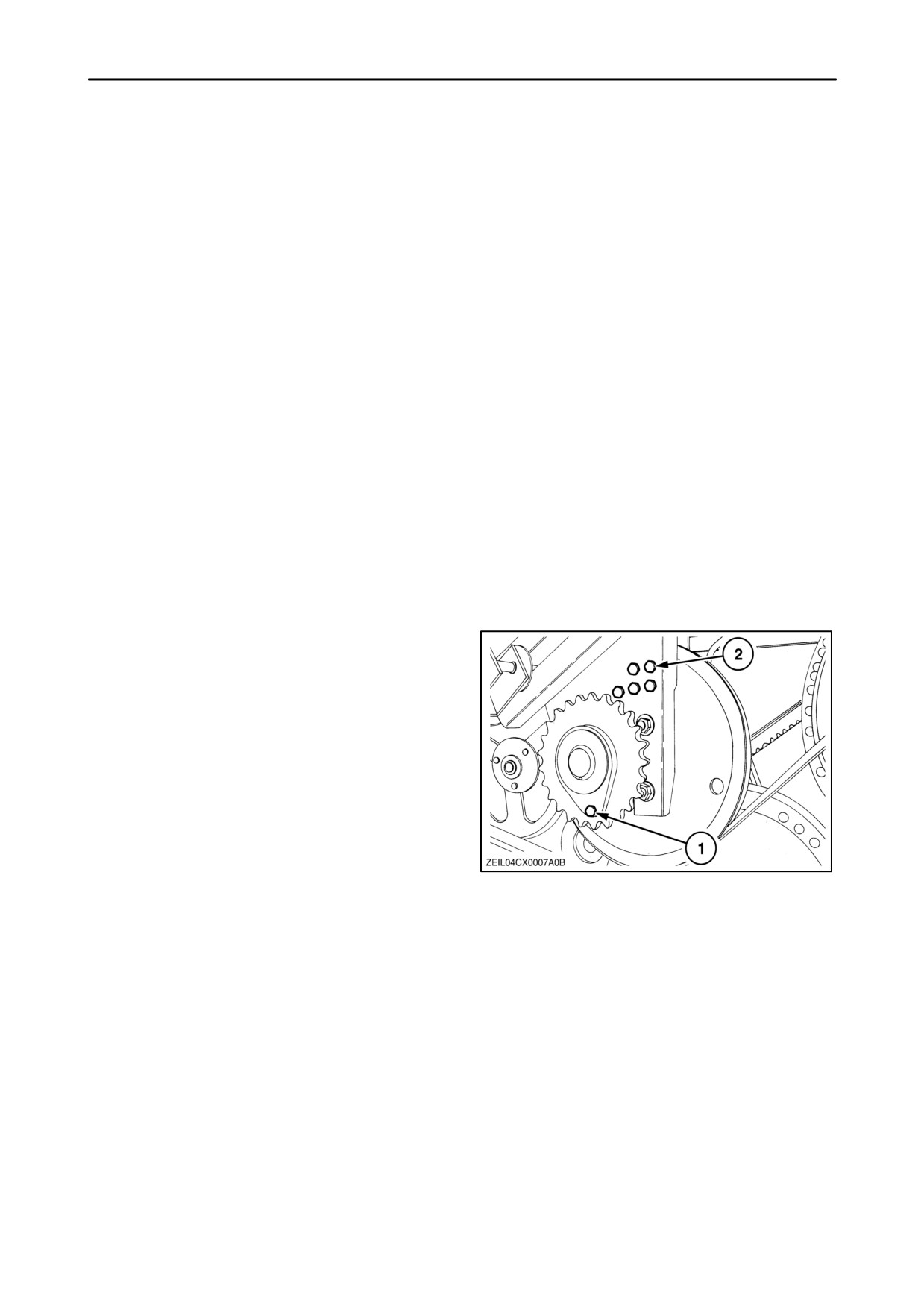
The unloading system drive is protected by a
shearbolt 1.
Spare shearbolts 2 are located above the sprocket.
NOTE: If repetitive shearbolt failures occur, adjust
cross auger covers down.
149
3-81
SECTION 3 - FIELD AND SITE OPERATION
STRAW HANDLING
Straw chopper (if installed)
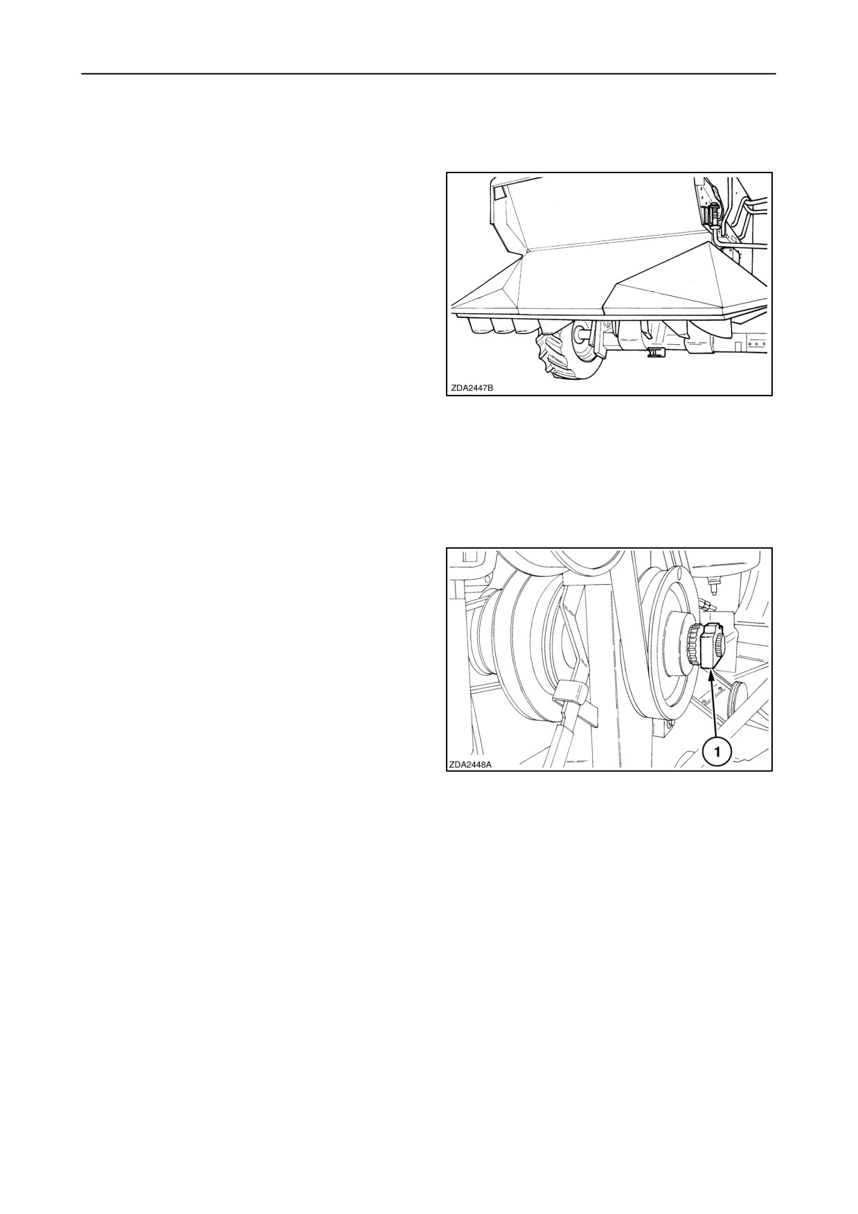
They are two type’s of straw choppers available:
• Small grain chopper with
4 rows of straight
knives. (Not suitable for working in maize)
• Heavy duty chopper:
- with 4 rows of bevelled knives.
- with 6 rows of bevelled knives.
(maize chop kit can be installed when working in
maize)
150
NOTE: Always stop the engine and wait until the
chopper rotor has come to a complete standstill
before working on the straw chopper.
Engaging of the straw chopper
The straw chopper starts when engaging the
threshing mechanism, if clutch
1 manually is
engaged.
NOTE: Keep yourself and other people away from
the rear of the combine when the straw chopper is
engaged and operating.
Do not use the straw chopper near the end of the field
if there is a risk that crop or stones can be projected
onto the public road.
151
NOTE: With the engine and the threshing
mechanism running, deflector plate in the chopping
position and the straw chopper not yet engaged
(manually) an alarm is given on the InfoViewt
display (+buzzer).
3-82
SECTION 3 - FIELD AND SITE OPERATION
Chopping cereals
For chopping cereals, proceed as follows:
1. Install the drive belt at high rpm speed of the
chopper rotor.
152
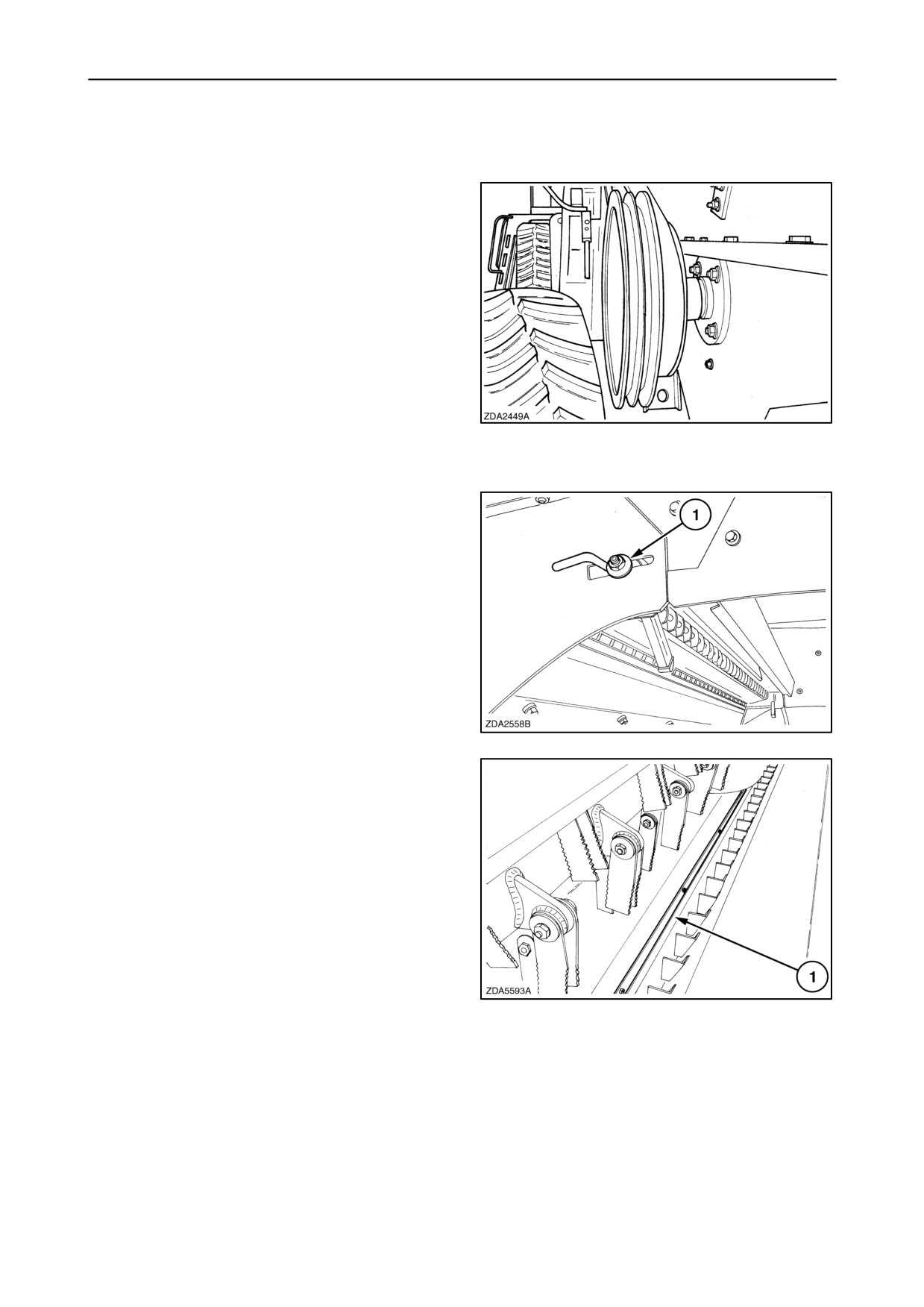
2. Adjustment of the counter knives: Loosen nuts 1
on both sides to move the counter knives more or
less in the rotor chamber.
• Counter knives:
- Fully engaged: For very fine chop quality.
- Approximately halfway: Damp heavy straw.
- Fully retracted: Dry straw (easy to chop)
153
• Shread bar 1: In easy chopping conditions or
if chop quality is not important, the shread bar
can be mounted underneath the chopper
body. (see fig. 157)
154
3-83
SECTION 3 - FIELD AND SITE OPERATION
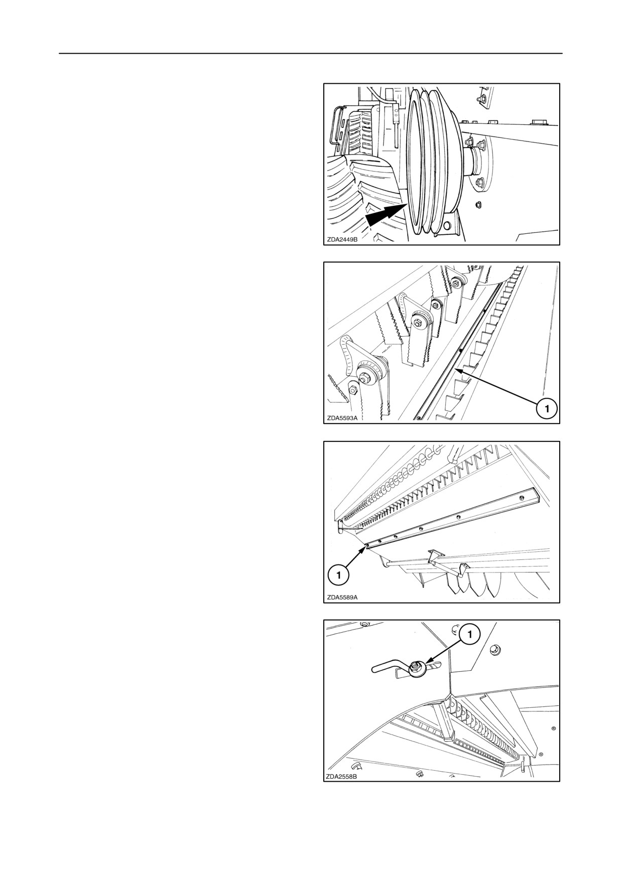
Chopping maize
For chopping maize, proceed as follows:
1. Install the drive belt at low rpm speed of the
chopper rotor.
155
2. Remove shread bar 1 by loosening the bolts.
156
3. Install shread bar 1 underneath the chopper body.
157
4. To keep the counter knives in good conditions for
the next cereal harvest is it better to remove the
counter knife bar by loosening nut 1 on both
sides.
158
3-84
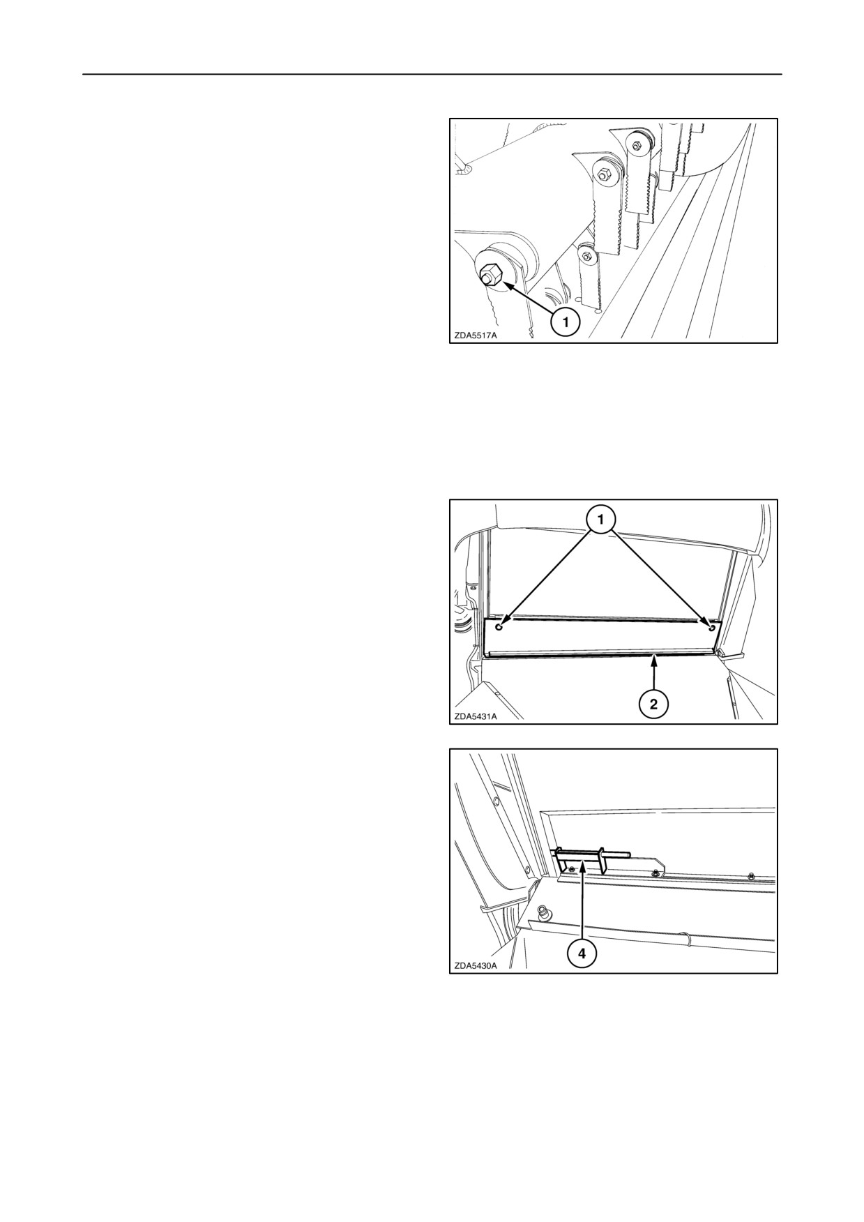
SECTION 3 - FIELD AND SITE OPERATION
5. Remove bolts 1 to reduce the rotor knives by
halve.
159
6. Install the deflector plate in maize configuration,
to protect the straw walkers.
To do this job, proceed as follows:
1. Set the deflector plate in the chopping position.
2. Turn screws 1 on both sides to open plate 2.
160
3. Unlock handle 4 and move them out of the holes
on both sides of the straw hood.
161
3-85
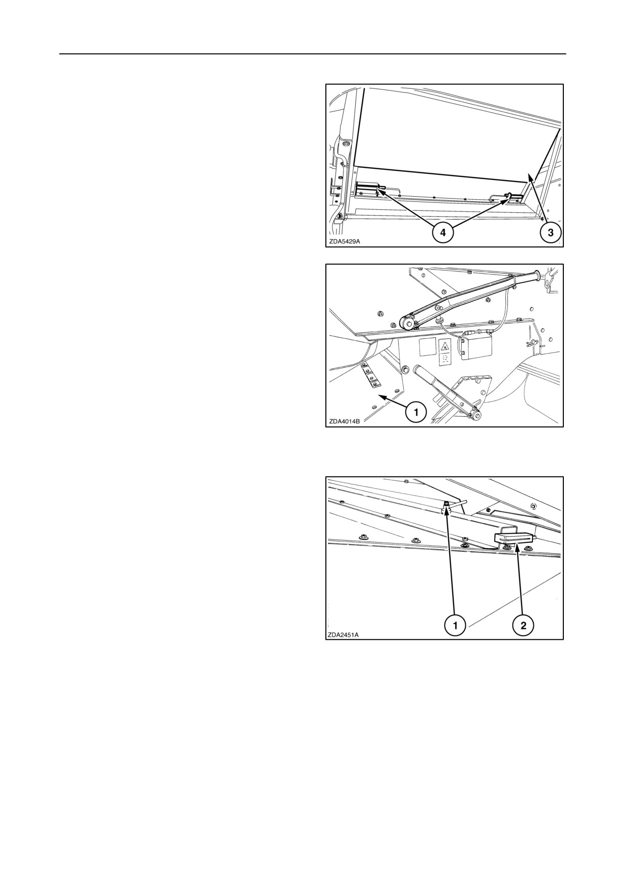
SECTION 3 - FIELD AND SITE OPERATION
4. Install plate 3 in the maize configuration and lock
with handles 4 into the holes foreseen on both
sides in the straw hood.
162
Straw chopper spreader chute
The spreader chute can be set in 7 different positions.
To adjust, use the handle on the right-hand side.
The straw chopper spreader chute 1 must remain in
the highest position (as shown) when driving on
public roads and also when the combine is pulling a
header trailer.
IMPORTANT: The spreader chute 1 must be up for
chopping and down for swathing.
163
Spread pattern
The spreader chute is foreseen with left and
right-hand side dividers that can be adjusted for
varying spreader widths, depending on the header
width.
To adjust, proceed as follows on both sides:
• Loosen nut
1 and move with handle 2 the
left-hand side dividers. Fix with nut 1.
164
3-86
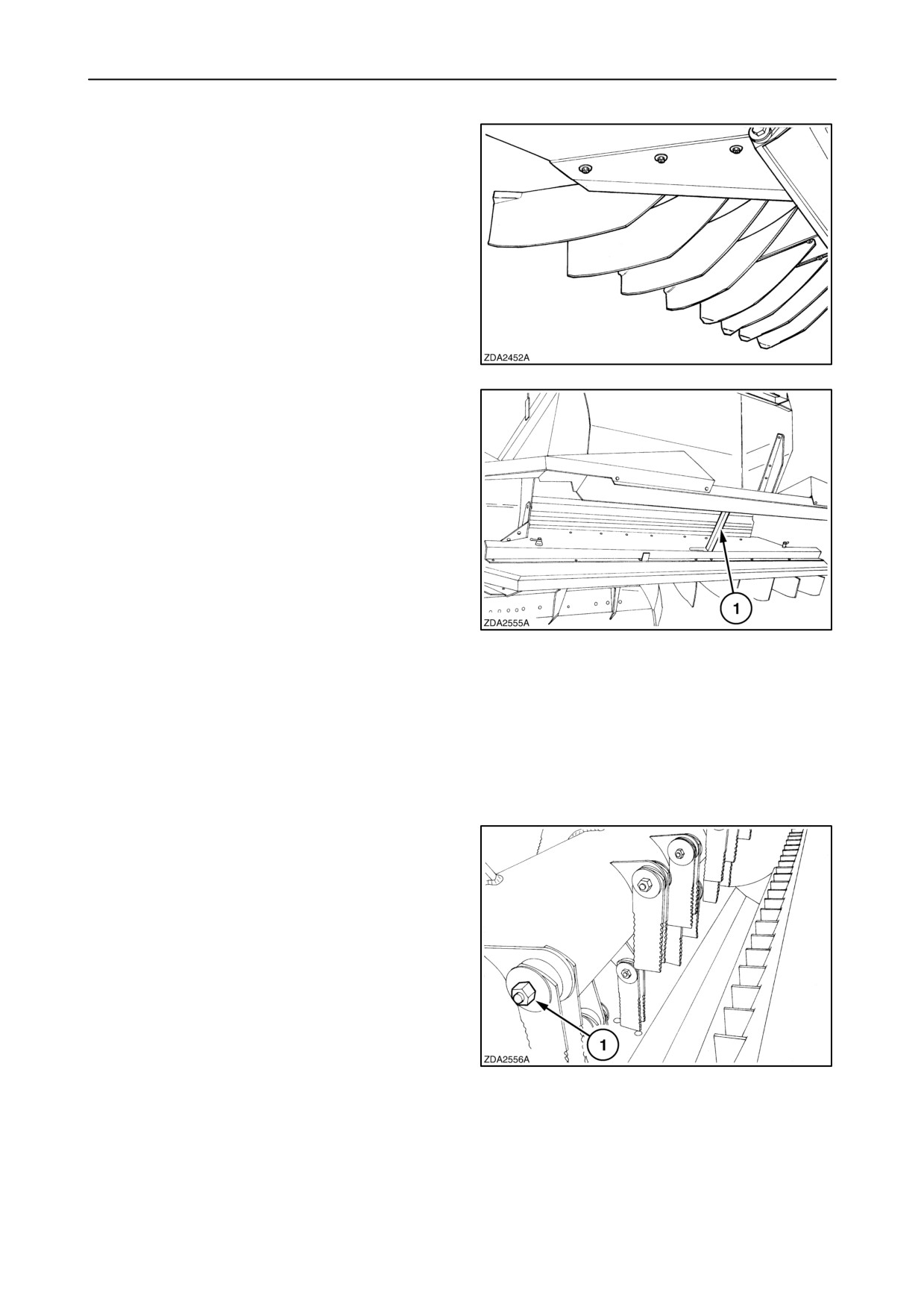
SECTION 3 - FIELD AND SITE OPERATION
Remote controlled divider plates (if installed)
With a selector switch from the cab it is possible to
move electrically the divider plates of the spreader
chute from left to the right and from right to the left,
depending on the wind direction and side slope.
165
Lift the swath plate up and block it with support 1 to
clean or service the chopper deflector plate.
166
Rotor knives
• Chopper rotor with 4 rows of knives.
CX700 models (56 hingeable rotor knives)
CX800 models (68 hingeable rotor knives)
• Chopper rotor with 6 rows of knives.
CX700 models (76 hingeable rotor knives)
CX800 models (92 hingeable rotor knives)
NOTE: Do not operate with broken or damaged
knives. This is unsafe and the unbalance may cause
severe secondary damage to the chopper and the
combine.
To replace the rotor knives, loosen lock nut 1 and
remove the washers, spacers and old knives.
When install the new knives, apply oil on the bushings
and the knife bores.
Check if the spacer is inserted with the small end into
the knife and the large end into the support.
167
Tighten locknut 1 with a torque of 79 Nm. (58 ft.lbs)
3-87
SECTION 3 - FIELD AND SITE OPERATION
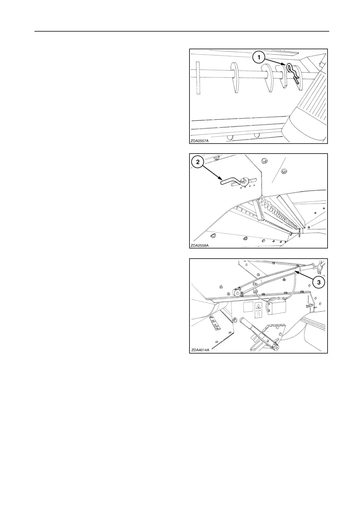
Counter knives
CX700 models: 28 counter knives
CX800 models: 33 counter knives
To remove, proceed as follows:
1. Remove hair pin 1.
168
2. Pull bar 2 out to change the counter knives.
To install, proceed in reverse order.
169
Swath-forming position
Adjust the deflector plate with handle 3 in swath
position.
170
3-88
SECTION 3 - FIELD AND SITE OPERATION
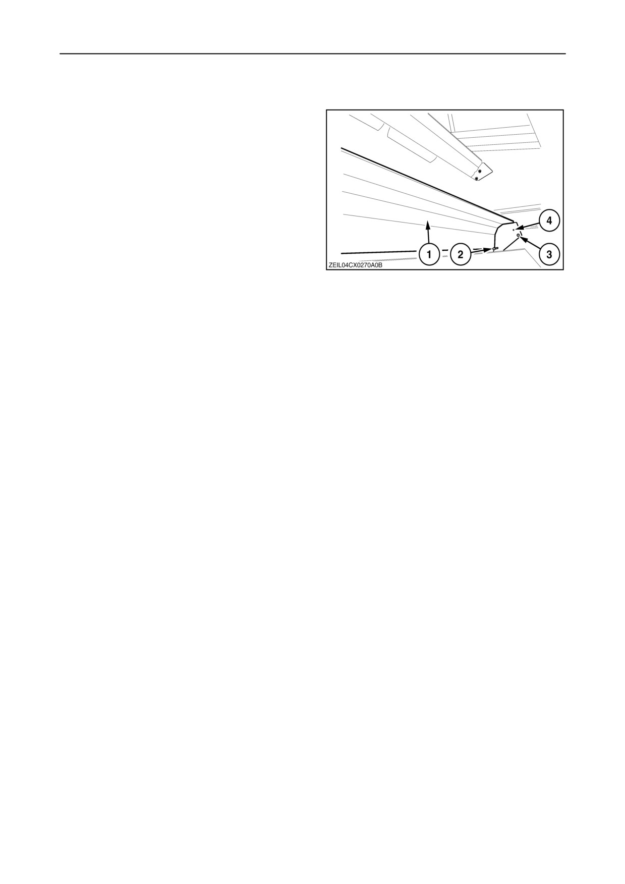
Baffle plate
The baffle plate (1) can be set in two positions:
• The front position (3) retains material longer and
give a fine chop.
• The rear position (4) gives a slightly longer chop,
but reduces power consumption and knife wear.
171
To change the position of the baffle plate (1), proceed
as follows:
On both sides:
1. Loosen the bolt (2) and remove the bolt (3).
2. Install the bolt (3) in position (4) and tighten the
bolts.
3-89
SECTION 3 - FIELD AND SITE OPERATION
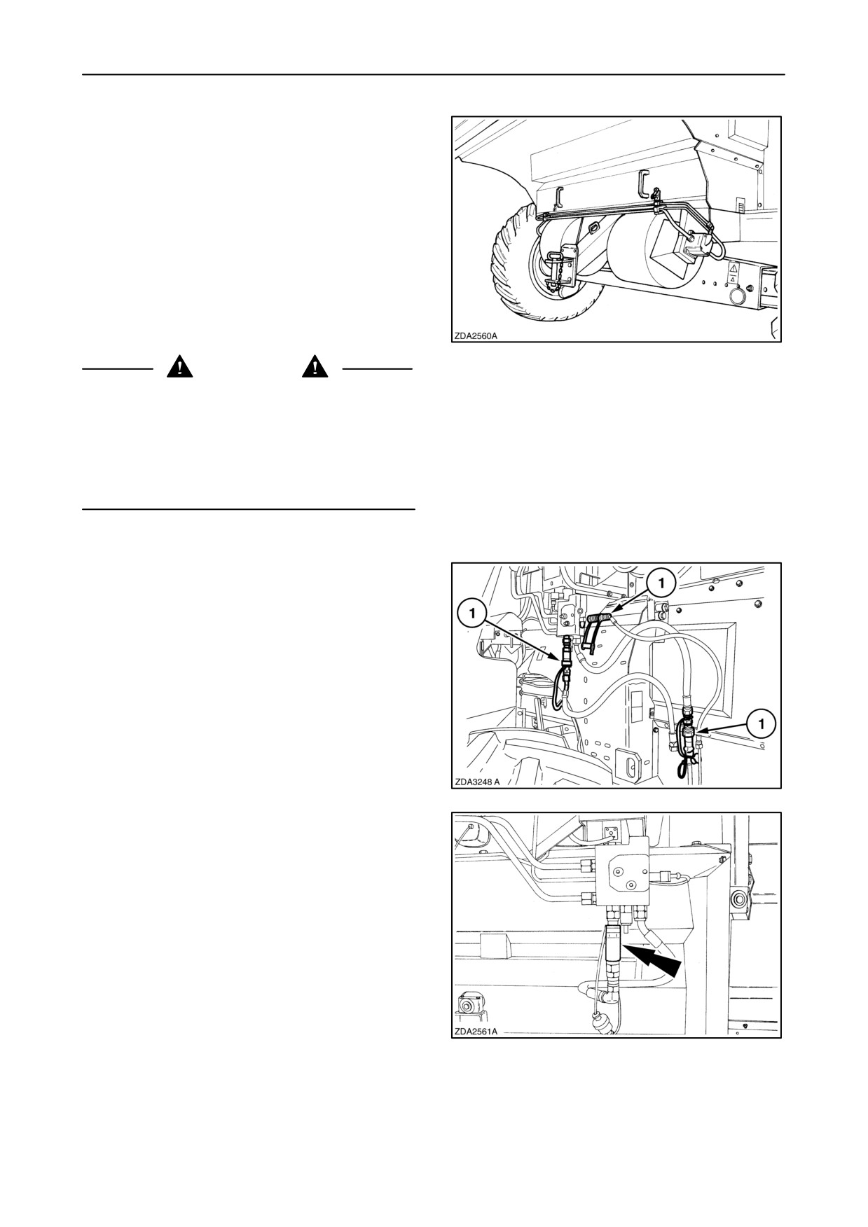
Chaff blower (if installed)
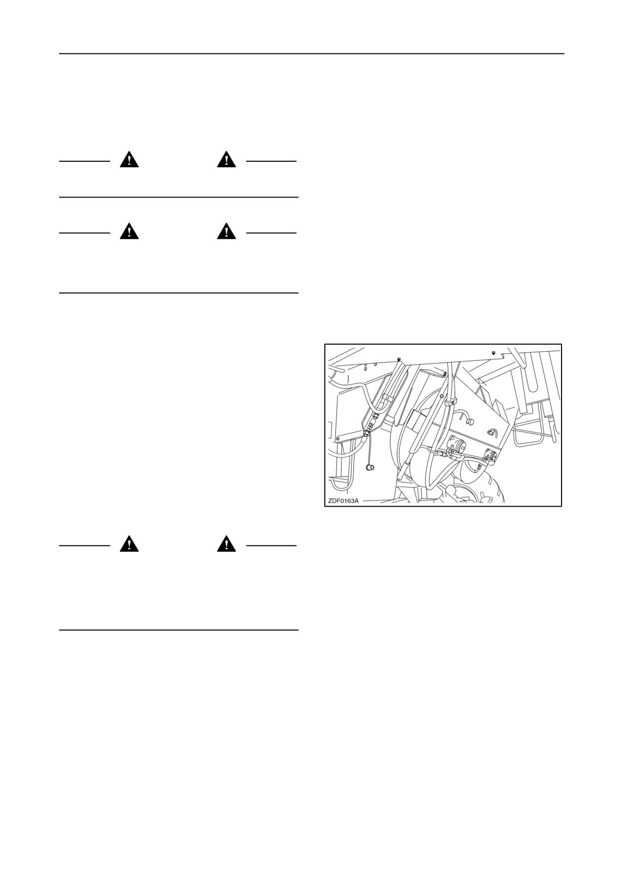
The chaff blower blows all the material coming from
the cleaning shoe into the straw chopper, to spread
the chaff evenly across the full cutting width of the
combine.
Remove the blower when threshing maize or
sunflowers.
172
CAUTION
Do not use the chaff blower without engaging the
straw chopper.
After disengaging the threshing mechanism, the
chaff blower will continue to run for 15 seconds before
disengaging to evacuate the remaining material.
Never disconnect the hydraulic couplers without
remove the chaff blower completely.
To remove the chaff blower proceed as follows:
1. Disconnect the hydraulic quick-couplers 1 of the
blower.
173
2. Connect the quick coupling as shown.
IMPORTANT: Avoid possible oil contamination by
properly fitting the blanking plugs into the hydraulic
quick couplers.
174
3-90
SECTION 3 - FIELD AND SITE OPERATION
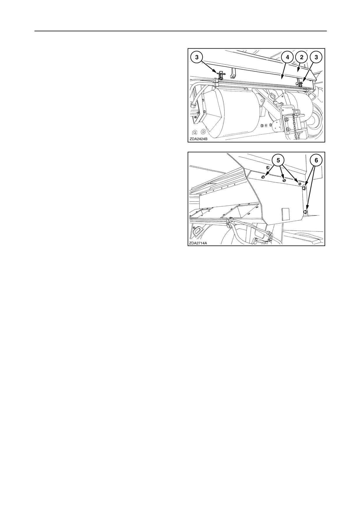
3. Open deflector plate 2 of the chaff blower.
4. Remove two hair pins 3 to open the locks.
5. Remove box 4 completely.
175
6. Remove three bolts 5 on both sides.
7. Remove two bolts 6 on both sides to remove the
chaff blower.
176
3-91
SECTION 3 - FIELD AND SITE OPERATION
Chaff spreader (if installed)
A chaff spreader can only be installed if the combine
is equipped without chaff blower and without straw
chopper to spread the chaff directly to the sides down
the ground.
CAUTION
Keep well clear off the chaff spreader at all times.
CAUTION
Never operating with an unbalanced chaff spreader.
Imbalance can cause damage on chaff spreader and
combine.
The chaff spreader has two positions:
• Forward position: For spreading the chaff into the
straw.
177
• Service position: To service or remove the sieves.
CAUTION
Always disengage the threshing mechanism and stop
the engine before working on the chaff spreader.
Wait until all the rotating parts come to a complete
standstill before working on the chaff spreader.
IMPORTANT: During field operation, the chaff
spreader must never be located in the service
position, even when it is not being used, as chaff
accumulation under the straw walkers may occur!
3-92
SECTION 3 - FIELD AND SITE OPERATION
Automatic rotation trailer hitch (If installed)
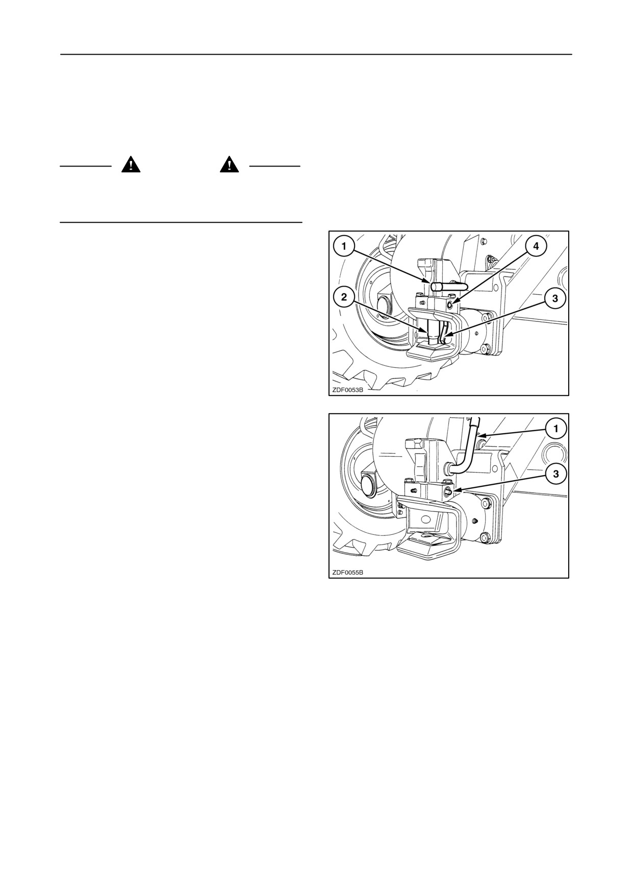
When your machine is equipped with a automatic
rotation trailer hitch, the following needs to be
respected.
CAUTION
For safety raisons , when not in use, close always the
hitch by pulling lever 1 down as shown in figure 178.
1. When attaching a trailer, pin 2 jumps down when
the lever 3 is pressed by the hook of the trailer.
2. The pin 2 is only closed perfectly when pin 4 is
completely in.
178
To open the hitch, proceed as follows:
1. Make sure that the combine and the trailer are
standing level and in one line and there is no
pressure between pin 2 (fig. 178) and the trailer
coupling.
2. To open the hitch, pull lever 1 upwards.
(pin 3 is coming out)
179
NOTE: To obtain a good working of the hitch, clean
and grease the hitch regularly.
IMPORTANT: The permitted vertical load and the
trailer weight is mentioned on a plate located on the
trailer hitch support.
3-93
SECTION 3 - FIELD AND SITE OPERATION
3-94
INDEX
Auto header lift
2-151
A
Auto reel speed slope
2-149
Access to machine components
1-34
Automatic Crop Settings
2-83
ACS mode screen
2-89
Automatic engine shut-off
2-170
ACS status
2-137
Automatic rotation trailer hitch
3-93, 7-24
Activating the ACS
2-85
Automatic Temperature Control (ATC)
2-25
Active alarms
2-162
Autopilot type
2-141
Active errors
2-163
Axial position of the steering axle
4-84
Additional mirror for Germany
1-43
Axle extensions kit
7-15
Adjustable chaffer 1-5/8” and 1-1/8”
7-10
Adjustment of the dimmed lights
1-45
B
Adjustment of the side lights
1-46
Aftercooler (CNH engine)
4-20
Baffle plate
3-89
Air compressor
4-120, 7-17
Base unit
1-1
Air compressor belt
4-66
Batteries
4-113
Air conditioning
4-117
Battery warning
1-15
Air conditioning drive belt (CNH engine)
4-66
Beater
3-55
Air co compressor drive belt
4-66
Beater blades
3-55, 7-5
Air intake system
4-31
Beater drive belt
4-58
Air reservoir specification
4-121
Beater pins
3-55, 7-5
Airborne Noise Emission
1-17
Beater wear plates
7-5
Alternator
4-115
Before driving the combine
3-1
Alternator drive belt (Iveco engine)
4-66
Bleeding the fuel system
4-29
Alternator, waterpump and air conditioning com-
Bleeding the fuel system (CNH engine)
4-28
pressor drive belt (CNH engine)
4-66
Brake fluid level
4-49
Anti-dust plate
3-43, 4-69
Brake system
4-49
Area harvested
2-54
Bubble-up drive chain
4-63
Attaching a trailer
1-50
Bubble-up gearbox
4-46
Attaching the header
3-20
Bubble-up sensor
2-157
Attachment Compatibility
1-51
Buzzer (if installed)
1-41
Audible alarm
2-170
1
Cleaning shoe
3-59
C
Cleaning system
3-59
Cab air filter
4-116
Climate control
2-23
Cab and Controls
2-1
Closed crankcase filter
4-19
Cab heating
7-18
Closz upper sieve
7-10
Cab roof controls
2-18
CNH Engine
4-55
Cab temperature selection
2-26
Combine Control Module
4-112
Cab/Climate control
4-116
Combine info screen
2-91
Calibration
2-71, 2-105, 2-106
Compensation mode
3-25
Calibration of the Concave position
2-114
Concave type
2-154
Calibration of the Ground speed hydrost.
2-122
Coolant change
4-21
Calibration of the Header
2-107
Coolant level
4-21
Calibration of the HGS Turntable actuator
2-128
Coolant specification
4-23
Calibration of the HGS Turntable sensor
2-135
Coolant system capacity
4-23
Calibration of the Lower sieve
2-117
Counter knives
3-88
Calibration of the Maximum stubble height 2-121
Concave clearance
3-45
Calibration of the Multifunction handle
2-112
Condenser
4-118
Calibration of the Self-levelling cleaning shoe
Configurations and Calibrations
2-92
2-118
Coolant heater
7-17
Calibration of the Spreader plates
2-120
Counterweights
8-44
Calibration of the Tyre radius
2-110
Counterweights support frame
7-25
Calibration of the Upper sieve
2-116
Crankcase breathing system (CNH engine)
4-19
Calibration of the Zero returns volume
2-125
Crankcase breathing system (Iveco engine) 4-18
Calibrations for SmartSteert system
2-127
Crop
2-159
Calibrations for yield Monitoring or Mapping 2-77
Crop calibration setup
2-72
Cereals threshing rebuild kit
7-6
Crop delay
2-160
Chaff blower
2-158, 3-90, 7-13
Crop distribution kit
7-1
Chaff spreader
3-92, 7-13
Crop edge calibration
2-134
Chains
4-47
Crop settings
2-86, 3-10
Chopper front drive belt
4-59
Crop settings and current settings
2-86
Chopper rear drive belt
4-60
Crop type
2-65
Chopping cereals
3-83
Current settings
2-90
Chopping maize
3-84
Custom Info screen
2-58
Cleaning
2-155, 4-70
Custom info screen setup
2-95
Cleaning fan
3-70
Cleaning fan variator drive belt
4-62
2
Engine gearbox
4-37
D
Engine RPM low alarm
2-138
Daily Start-up procedure
3-2
Engine sump and filter capacity
4-17
Data logger
2-74, 7-23
Error handling
2-102
De-awning plates
3-54
Error history
2-164
De-awning slats
7-4
Extended sieve dividers
7-11
Detaching the header
3-22
DGPS
2-78, 7-22
F
Diagnose info screen
2-161
Diesel fuel
1-14
Fan bottom shield
7-8
Differential lock
3-5
Feeding
4-67
Dimensions
8-40
Filling the fuel tank
4-24
Display settings
2-99
Filter-drier
4-119
Draper header (92C/94C)
1-4
Final drive gearboxes,
4-42
Drive belts and chains - Left-hand side
4-52
Fire extinguisher
1-44, 7-26
Drive belts and chains - Right-hand side
4-54
Fixed cleaning shoe drive belt
4-59
Drive belts - Engine compartment
4-55
Fixed cleaning shoe intermediate shaft drive belt
4-58
Drum and concave
3-43
Flex header
1-3
Drum and concave type of use
3-46
Flex header operation
3-27
Drum drive belt
4-57
Fluid change
4-49
Drum variator drive belt
4-57
Fluid specification
4-49
Driving the combine
3-3
Flip-up light kit
7-19
Drum blockage
3-44
Foldable ladder
7-16
Drum speed
3-44
Foot brakes
4-79
Dual speed
7-15
Frame counterweights
7-25
Fresh air intake grill
4-118
E
Front Face Adjustment
4-68
Elapsed time
2-54
Fuel cooler
7-17
Electrical system
4-107
Fuel filter (CNH engine)
4-27
ElectroMagnetic Compatibility
1-17
Fuel filter (Iveco engine)
4-29
Electronic module (CCM3)
7-20
Fuel level
4-23
Emergency exit
2-1
Fuel prefilter/water separator
4-26
Emergency stop
3-4
Fuel specification
4-25
End-Of-Season Service
6-1
Fuel storage
4-26
Engaging of the straw chopper
3-82
Fuel supply pump
4-27
Engine
1-2, 1-13, 4-14, 7-17
Fuel system
4-23
Engine cooling system
4-21
Fuel tank capacity
4-24
Engine fan drive belt
4-65
Fuses and relays
4-107
3
Header/straw elevator intermediate drive belt
G
4-60
Gear shifting system
3-5
Header and straw elevator reversing system
3-35
Gearshifting
5-12
Header Autofloatt
2-149
General recommendations
1-6
Header Height Controls
3-23
GPS
2-78, 7-22
Header lateral float
2-149
Graepel sieve extension
7-10
Header lift cylinder kit
7-3
Grain elevator chain
4-64
Header lift cylinders
2-150
Grain elevator drive chain
4-64
Header lower rate
2-148
Grain elevator intermediate shaft drive belt
4-61
Header platform type
2-145
Grain flow sensor
4-76, 7-21
Header raise rate
2-147
Grain header
1-3
Header threshold pressure
2-148
Grain header road light kit
7-2
Header trailer hitch
7-24
Grain pan divider kit
7-9
Header type
2-143
Grain pan/ upper sieve distribution
3-17
Header usage
2-146
Grain sample access
3-77
Header width
2-146
Grain storage
4-72
Height sensitivity
2-152
Grain storage/Unloading
3-73
High fan speed kit
7-17
Grain tank extensions
3-78
How to obtain an idea on loss level
3-19
Grain tank extensions with covers
3-78
Hydraulic and Hydrostatic system
4-33
Grain tank filling system
3-73
Hydraulic deck plates
2-153
Grain tank level sensor
3-79
Hydraulic equipment
4-80
Grain tank sample
3-16
Hydraulic reel rebuild kit
7-1
Grain tank unloading auger
3-80
Hydraulic valve electrics
5-14
Grain tank window
3-77
Grain - Rice - Flex header (71C/73C)
1-4
Grass seed variator kit
7-8
I
Grease fittings and intervals
4-1
In cab printer
2-169, 7-18
Grease interval
4-3
Indicator lights
2-139
Grease specification
4-1
InfoViewt Monitor
2-38, 2-40
Instantaneous values
2-61
H
Intended use
1-1
Intermediate plate
3-36
Harvesting
3-6
Intermediate roll
4-67, 7-2
Harvest Info screen
2-59
Iveco engine
4-55
Harvest summary
2-66
Header
3-20
Header and straw elevator drive belt
4-61
K
Header drive belt
4-61
Kill stall
3-16
Header standard safety latch
1-40
4
Multi-thresh system
3-57
L
Language
2-101
N
LCD contrast
2-100
LCD night brightness
2-100
Narrowing plates
7-3
Left-hand returns auger and returns cross auger
Network
2-168
drive belt
4-59
Legal Obligations
1-16
O
Level sensor
4-74
Lifting the combine
1-48
Operating the attachments
1-11
Operating the combine
1-10
Light extension kit
7-20
Lighting and Mirrors
2-32
Operator’s seat and Surroundings
2-2
Option module CCM 3
2-137
Limitation of the lateral float system
3-37
Longitudinal inclination
2-156
Ordering Parts/ Accessories
6-2
Losses
3-17
Other components
2-35
Lower shaft adjustment
3-33
Lower sieve type
2-156
P
Low speed fan variator kit
4-63
Parking brake
3-4, 4-79
Lubrication schedule
4-50
Perforated covers
7-12
Perforated straw elevator floor section
7-2
M
Performance indicators
3-16
Main drive belt
4-57
Petersen1-1/8”
7-10
Pivot axle
4-70
Main info screen
2-55
Main info screen setup
2-94
Pivot plate 127 mm
7-16
Pivot points
4-48
Maintenance
1-11
Maize concave
3-45, 7-7
Portable work light
7-20
Maize header
1-3
Potentiometer flex header 19 ft
7-3
Powered rear axle
7-15
Maize header (96C)
1-4
Maize threshing rebuild kit
7-7
Pre-separator
4-20
Manual controller
2-24
Precision farming
2-159
Premium speakers
7-18
Manual release of the hydraulic parking brake
5-11
Preseason Service
6-3
Marker setup
2-68
Presieve
3-64, 3-67
Maximum stubble height
2-150
Presieve HC 1-5/8”
7-9
Minimum reel speed
2-148
Product identification
1-1
Moisture sensor
4-72, 7-21
Prohibited usage
1-1
Moisture sensor fin
4-73
Protective Devices
1-40
Multi-Function Handle
2-12
5
Row distance
2-147
R
Rows in use
2-146
Rear revolving flash light
7-19
Rear wheel assist
2-141
S
Recirculation filter
4-118
Reel drive type
2-150
Safety decals
1-18
Reel fore-back
2-151
Safety decals (Australia)
1-27
Reel horizontal position
2-152
Safety guards
1-43
Reel speed sensor
2-152
Safety railing
1-42
Reel to ground speed synchronization 3-27, 3-28
Safety Requirements
1-16
Reel vertical position
2-151
Saving ACS user settings
2-86
Remote controlled divider plates
3-87
Select active load
2-63
Remote deflectors control
7-14
Self-levelling cleaning shoe drive belt
4-58
Remote lower sieve
2-157
Self-levelling cleaning shoe intermediate shaft
drive belt
4-58
Remote sieve control
7-8
Sensitivity setting of straw walker and sieve loss
Remote spreader plates
2-158
sensor
2-56
Remote upper sieve
2-157
Sensor selection
2-71
Removable grain pan
3-59
Separation
3-55
Replacement of the drum concave
3-46
Service
2-166
Residue
2-158
Service info screen
2-161
Returns sample
3-17
Setting of different types of concaves
3-53
Returns system
3-71
Setting of the returns capacity
2-57
Revolving flash lights
7-19
Shaft Speed Monitor
2-15
Rice concave
3-45
Side hill weights
7-1
Rice pins
7-4
Sieve installation
3-67
Rice threshing rebuild kit
7-7
Sieve loss sensitivity
2-155
Right-hand module
2-7
Sieve openings
3-62
Right-hand returns auger drive belt
4-62
Sieve position
3-64
Road info screen
2-53
Sieve removal
3-64
Road info screen setup
2-93
Sieves
3-62, 4-70
Rotary dust screen and Cooling system
4-30
Signal plates
1-42, 7-25
Rotary dust screen brush
7-17
Signal plates for Italy
1-42, 7-26
Rotary dust screen drive belt
4-65
Slip clutch
4-67, 4-72
Rotary dust screen interm. shaft drive belt
4-65
Small grain concave
3-45
Rotary screen brush
2-138
SmartSteert system
7-23
Rotary separator
3-56
Smooth rotor thresher covers
7-11
Rotary separator drive belt
4-60
Speaker volume
2-100
Rotation header trailer hitch
7-24
Specifications
8-1
Roto-threshers
4-71
Spread pattern
3-86
Rotor knives
3-87
SSM lcd backlight
2-101
Round hole sieve
7-9
Stability
1-16
Round hole sieve frame
7-9
6
Stainless steel curved louver maize upper sieve
T
7-10
Start module
2-17
Technical data
8-30
Starting the engine
3-2
Threaded rods
4-48
Starting up the combine
1-8
Thresher loss sensitivity
2-158
Steering axle
4-83
Threshing
3-43, 4-69
Steering axle height position
4-86
Tie downs for shipping
1-49
Steering axle position
4-84
Tilt sensitivity
2-153
Steering column
2-5
Tilt/Knife position valve
2-153
Steering cylinder adjustment
4-106
Toe-in adjustment
4-104
Steering platform extensions
7-16
Tool to remove the concave
7-4
Stone door open sensor
2-154
Total rows
2-147
Stone trap
3-42
Towing the combine
1-47
Stopping the combine
1-11
Track width position
4-87
Stopping the engine
3-3
Tracks
4-81, 7-16
Straight steer calibration
2-133
Tracks type
2-141
Straw chopper
3-82, 7-14
Traction gearbox
4-40
Straw chopper rpm sensor
2-158
Transport mode
3-27
Straw chopper spreader chute
3-86
Travelling on public roads
1-9
Straw chopper wind knife kit
7-14
Trip distance
2-54
Straw elevator
3-33, 3-38
Turbocharger compressor (CNH engine)
4-20
Straw elevator bottom plate
3-37
Types of sieves available
3-69
Straw elevator drive
7-2
Tyre radius
2-140
Straw elevator drive belt
4-61
Straw elevator chain
4-56, 4-67
U
Straw flow beater
3-57
Unit system
2-102
Straw handling
3-82
Unloading
2-157
Straw retarding curtain
3-58
Unloading drive belt
4-57
Straw walker drive belt
4-59
Unloading drive chain
4-60
Straw walker raisers
7-6
Unloading mechanism
3-81
Straw walkers
3-58
Unload tube signal plate+light
7-26
Stubble height and Autofloatt mode
3-23
Unloading drive gearbox
4-44
Sunflower cover plate
7-5
Unloading tube extension
7-12
Swath-forming position
3-88
Unloading tube gearbox
4-45
Swath plate sensor
2-158
Unloading tube swing
3-81
Upper sieve type
2-156
7
Wheel counterweights
7-25
V
Wheel nuts torque
8-1
Vertical covers on straw walkers
7-6
Wheel spacer
7-16
Vertical knife electricity kit
7-5
Wheels and tyres
8-1
Vertical knives
2-151
Wide fender
7-26
Vibration Level Information
1-17
Windscreen washer system
7-18
W
Y
Waterpump drive belt (CNH Engine)
4-66
Yield logging package
7-23
Waterpump drive belt (Iveco engine)
4-66
Yield mapping package
7-22
Wheel chock
1-41
Yield monitoring package
7-21
8
CNH BELGIUM N.V., Leon Claeystraat 3A, B-8210 ZEDELGEM - Belgium
AFTER SALES - Technical Information
Print No. 604.63.341.00 - 7th Edition - 07 - 2005
PRINTED IN BELGIUM
COPYRIGHT BY CNH BELGIUM N.V.
All rights reserved. No part of the text or illustrations of
this publication may be reproduced.
New Holland policy is one of continuous improvement and the right to change prices, specification or equipment
at any time without notices is reserved.
All data given in this publication is subject to production variations. Dimensions and weight are approximate only
and the illustrations do not necessarily show products in standard condition. For exact information about any
particular product, please consult your New Holland Dealer.

CX720 CX820
CX740 CX840
CX760 CX860
CX780 CX880
OPERATOR’S MANUAL
Volume 2/2 - Maintenance
GENERAL
This manual has been prepared to assist you in the correct procedure for running in, driving, operating, adjusting
and maintaining your new machine.
This machine has been designed and built to give maximum performance, economy and ease of operation under
a wide variety of crops and conditions.
Prior to delivery, your machine was carefully inspected both at the factory and by your dealer to ensure that it
reaches you in optimum condition. To maintain this condition and ensure trouble-free operation it is important
that routine services, as specified in this manual, are carried out at the recommended intervals.
Before attempting to drive or operate your machine, read this manual carefully (especially the chapter covering
the Safety Precautions) and keep it in a convenient place for future reference.
’’Left” and ’’right” used throughout this manual are determined from the rear, facing in the direction of travel of
the machine during operation.
If at any time you require advice concerning your machine, do not hesitate to contact your authorised dealer.
He has factory-trained personnel, genuine service parts and the necessary equipment to carry out your service
requirements.
IMPORTANT:
This machine has been designed and built according to the European Directive 98/37/EC.
Always use genuine New Holland Service parts or parts matching at least the same quality, reliability and
functionality as the equivalent original Service Parts when servicing and repairing your machine and do not
modify your machine without a written permission of the manufacturer. Failure to do so will void the responsibility
of the manufacturer.
An EC Declaration of Confirmity is separately delivered with your machine.
Store this EC Declaration into the storage space for your Operator’s Manual (refer to section 2 - Controls,
Instruments and Operation).
The maximum road speed of your machine is limited electronically. Do not try to change it.
Check local road legislation before driving the machine on public roads.
When operating interchangeable New Holland built equipment, ensure the equipment is CE approved.
As this publication is distributed throughout our international network, the equipment illustrated, either as
standard or as an accessory, may vary according to the country in which the equipment is to be used. Low cost
configurations, as chosen by the customer, may deviate from the specifications given.
Several figures in this manual show the safety guarding or the additional guards, legally required by certain
countries, open or removed to illustrate better a particular feature or adjustment. The machine must not be used
in this condition. For your own safety, ensure that all guards are closed or replaced before operating the machine.
OWNER ASSISTANCE
We at New Holland and your New Holland dealer want you to be completely satisfied with your investment.
Normally your dealer’s Service Department will handle any problems with your equipment. Sometimes, however,
misunderstanding can occur. If your problem has not been handled to your satisfaction, we suggest contacting
the owner or General Manager of the dealership, explaining the problem, and requesting assistance. When
additional assistance is needed, your dealer has direct access to our branch office.
COMPANY POLICY
Company policy, which is one of continuous improvement, reserves the right to make changes in design and
specification at any time without notice and without obligation to modify units previously built.
All data given in this book is subject to production variations. Dimensions and weights are approximate only and
the illustrations do not necessarily show the machine in standard condition. For exact information about any
particular machine please consult your Dealer.
ACCESSORIES AND OPTIONS
Your machine has been designed to operate in a wide variety of crops and conditions. Nevertheless additional
equipment may, in certain cases, be required to improve the machine performance. A list of this additional
equipment is given in the ’’Options and Accessories” section in this manual.
PARTS AND ACCESSORIES
Genuine New Holland parts and accessories have been specifically designed for New Holland machines.
We would like to point out that ’’nongenuine” parts and accessories have not been examined and released by
New Holland. The installation and/or use of such products could have negative effects upon the design
characteristics of your machine and thereby affect its safety. New Holland is not liable for any damage caused
by the use of ’’nongenuine” parts and accessories.
Rely on your authorised dealer to supply you with genuine New Holland parts only. These parts are covered by
our warranty and will give you the best performance.
When ordering service parts, always quote the model and serial number, as well as the year of manufacture
printed on the manufacturer’s identification plate (refer to chapter General Information).
LUBRICANTS
Your dealer sells a selection of specially formulated lubricants based on own engineering specifications.
Recommended lubricants for your machine are listed on the inside back cover of this manual.
WARRANTY
Your machine is warranted according to legal rights in your country and the contractual agreement with the selling
dealer. No warranty shall, however, apply if the machine has not been used, adjusted and maintained according
to the instructions given in this Operator’s Manual.
It is prohibited to carry out any modifications to the machine unless specifically authorised, in writing, by a New
Holland representative.
CLEANING YOUR MACHINE
Your machine is a state-of-the-art machine with sophisticated, electronic controls. Even though every
precaution has been taken to safeguard electronic components and connections, the pressure generated by
some pressure washers is such that complete protection against water ingress cannot be guaranteed.
When using a high pressure washer, do not stand too close to the machine and avoid directing the jet at electronic
components, electrical connections, breathers, seals, filler caps, etc.
IMPORTANT ENVIRONMENTAL CONSIDERATIONS
Soil, air and water are vital factors of agriculture and of life in general. Where legislation does not yet rule the
treatment of some of the substances, which are required by advanced technology, common sense should govern
the use and the disposal of the products of a chemical and a petrochemical nature.
The following are recommendations, which may be of assistance:
Become acquainted with and respect the relative legislation applicable in your country.
Where no legislation exists, obtain information from suppliers of oils, fuels, antifreeze, cleaning agents, etc. for
their effect on man and nature and for safe ways of storage, usage and disposal. Agricultural consultants will,
in many cases, be able to help you as well.
HELPFUL HINTS
Avoid filling fuel tanks using jerrycans or inappropriate pressurized fuel delivery systems which may cause
considerable spillage.
In general, avoid skin contact with all oils, acids, solvents, etc. Most of them contain substances which can be
harmful to your health.
Use biodegradable oils for chain lubrication where oils cannot be recuperated. In many countries rapeseed oils
or other agro-based lubricants have become available.
Modern oils contain additives. Do not burn contaminated fuels and/or waste oils in ordinary heating systems.
Avoid spillage when draining off used engine coolant mixtures, engine, gearbox and hydraulic oils, brake fluids,
etc. Do not mix drained brake fluids, fuels or coolant mixtures with lubricants. Store them safely until they can
be disposed of in a proper way to comply with local legislation and available resources. They should not be
allowed to get into the soil but should be collected and disposed of safely.
Do not open the air-conditioning system yourself; it contains gases, which should not be released into the air.
Your dealer has a special extractor for this purpose and will have to do the recharging of the system anyway.
Repair any leaks or defects in the engine cooling or the hydraulic system immediately.
Do not increase the pressure in a pressurized circuit as this may lead to bursting of the components.
Protect hoses during welding as penetrating weld splatter may burn a hole or weaken them, causing the loss
of oils, coolant, etc.
Battery recycling
Batteries and electric accumulators contain various components which can damage the environment if they are
not properly recycled after usage. New Holland strongly recommends that you return all used batteries (starting
batteries and small ”dry” batteries which may be used in electric or electronic systems) to your New Holland
dealer who will ensure proper disposal or recycling. In certain countries this is a legal requirement.
e2005 CNH Belgium NV-Zedelgem
SECTION QUICK REFERENCE
1 - General Information and Safety
2 - Controls, Instruments and Operation
3 - Field and Site Operation
4 - Lubrication and Maintenance
5 - Fault Finding
6 - Vehicle Storage
7 - Accessories
8 - Specification
9 - 1st 50 Hour Service Sheets
Index
NOTE: The CX Operator’s manual consists of two volumes. The first volume “Operation“
with sections 1,2 and 3, the second volume “Maintenance” with sections 4,5,6,7,8 and 9.
TABLE OF CONTENTS
Title
Page
(Volume 1/2 - Operation)
SECTION 1 - GENERAL INFORMATION AND SAFETY
Intended use
1-1
Product identification
1-1
Base unit
1-1
Engine
1-2
Grain header (High-Capacity, Extra-Capacity or Varifeedt)
1-3
Maize header
1-3
Flex header
1-3
Maize header (98C)
1-4
Draper header (92C/94C)
1-4
Grain - Rice - Flex header (72C/74C)
1-4
Record below the serial numbers of your machine for quick reference:
1-5
General recommendations
1-6
Starting up the combine
1-8
Travelling on public roads
1-9
Operating the combine
1-10
Operating the attachments
1-11
Stopping the combine
1-11
Maintenance
1-11
Engine
1-13
Diesel fuel
1-14
Battery warning
1-15
Illustrations
1-15
Stability
1-16
Legal Obligations
1-16
Safety Requirements
1-16
Airborne Noise Emission
1-17
ElectroMagnetic Compatibility (EMC)
1-17
Vibration Level Information
1-17
Safety decals
1-18
Safety decals (Australia)
1-27
Access to machine components
1-34
Protective Devices
1-40
Header standard safety latch
1-40
Extra safety latch
1-41
Wheel chock
1-41
Buzzer (if installed)
1-41
Safety railing for straw elevator
1-42
Signal plates
1-42
Signal plates for Italy
1-42
Safety guards
1-43
Additional mirror for Germany
1-43
Fire extinguisher (with chopper drive)
1-44
Adjustment of the side lights
1-46
i
Towing the combine
1-47
Lifting the combine
1-48
Tie downs for shipping
1-49
Attaching a trailer
1-50
Attachment Compatibility
1-51
European models
1-51
Australian models
1-53
SECTION 2 - CONTROLS, INSTRUMENTS AND OPERATION
Cab and Controls
2-1
Emergency exit
2-1
Operator’s seat and Surroundings
2-2
Steering column and Control pedals
2-5
Right-hand module
2-7
Multi-Function Handle
2-12
Shaft Speed Monitor (SSM)
2-15
Start module
2-17
Cab roof controls
2-18
Climate control
2-23
1. Manual controller
2-24
2. Automatic Temperature Control (ATC)
2-25
Error table
2-27
Lighting and Mirrors
2-32
Other components
2-35
InfoViewt Monitor
2-38
InfoViewt Monitor
2-40
Menus and sub-menus
2-50
MDM Protected mode
2-52
I Road info screen
2-53
Elapsed time
2-54
Trip distance
2-54
Area harvested
2-54
II Main info screen
2-55
General
2-55
Sensitivity setting of straw walker and sieve loss sensor
2-56
Setting of the returns capacity
2-57
III Custom Info screen
2-58
IV Harvest Info screen
2-59
1. Instantaneous values
2-61
Instantaneous parameter list
2-62
2. Select active load
2-63
Select or create Farm, Field, or Load name
2-63
Farm name
2-63
Crop type
2-65
3. Harvest summary
2-66
Harvest summary parameter list
2-67
4. Marker setup
2-68
5. Calibration
2-71
Sensor selection
2-71
Crop calibration setup
2-72
Perform crop calibration
2-73
Data logger (if installed)
2-74
ii
Calibrations for yield Monitoring or Mapping
2-77
(Differential) Global Positioning System - (D)GPS (if installed)
2-78
V Automatic Crop Settings
2-83
General
2-83
Factory default values (Automatic Crop Settings)
2-84
Activating the ACS
2-85
Saving ACS user settings
2-86
Crop settings and current settings
2-86
Crop settings
2-86
ACS mode screen
2-89
Current settings
2-90
VI Combine info screen
2-91
VII Configurations and Calibrations
2-92
1. Road info screen setup
2-93
2. Main info screen setup
2-94
3. Custom info screen setup
2-95
Page Setup
2-96
4. Display settings
2-99
LCD contrast
2-100
LCD night brightness
2-100
Speaker volume
2-100
SSM lcd backlight
2-101
Language selection
2-101
Unit system
2-102
Error handling
2-102
5. Calibration
2-105
Calibrations for Basic operation
2-106
Calibration of the Header
2-107
Calibration of the Tyre radius (ground speed)
2-110
Calibration of the Multifunction handle
2-112
Calibration of the Concave position
2-114
Calibration of the Upper sieve
2-116
Calibration of the Lower sieve
2-117
Calibration of the Self-levelling cleaning shoe
2-118
Calibration of the Spreader plates
2-120
Calibration of the Maximum stubble height
2-121
Calibration of the Ground speed hydrostatic
2-122
Calibration of the Zero returns volume
2-125
Calibrations for SmartSteert system (If installed)
2-127
Calibration of the HGS Turntable actuator
2-128
Calibration of the HGS Turntable sensor
2-135
6. Combine
2-137
7. Engine
2-138
8. Electrical
2-139
9. Hydraulics
2-139
10. Driveline
2-140
11. Header
2-142
12. Straw elevator
2-154
13. Threshing
2-154
14. Cleaning
2-155
15. Clean grain/Unloading
2-157
16. Residue
2-158
17. Precision farming
2-159
VIII Diagnose info screen
2-161
iii
IX Service info screen
2-161
1. Active alarms
2-162
2. Active errors
2-163
3. Error history
2-164
4. Service
2-166
5. Network
2-168
Audible alarm
2-170
Automatic engine shut-off
2-170
SECTION 3 - FIELD AND SITE OPERATION
Before driving the combine
3-1
Starting the engine
3-2
Daily Start-up procedure
3-2
Stopping the engine
3-3
Driving the combine
3-3
Parking brake
3-4
Emergency stop (If configured in InfoViewt)
3-4
Gear shifting system
3-5
Differential lock (if equipped)
3-5
Harvesting
3-6
Description of operation
3-6
Crop settings
3-10
To change from grain to maize configuration, the following modifications has to be done.
3-14
Kill stall
3-16
Performance indicators
3-16
Grain tank sample
3-16
Grain pan/ upper sieve distribution
3-17
Returns sample
3-17
Losses
3-17
How to obtain an idea on loss level
3-19
Header
3-20
Attaching the header to the combine
3-20
Detaching the header from the combine
3-22
Header Height Controls
3-23
Flex header operation
3-27
Auto header lift
3-27
Reel to ground speed synchronization
3-28
SmartSteert System (if installed)
3-30
Feeding/Straw elevator
3-33
Lower shaft adjustment
3-33
Header and straw elevator reversing system
3-35
Intermediate plate
3-36
Straw elevator bottom plate (if installed)
3-37
Limitation of the lateral float system
3-37
Straw elevator - Removal and Installation
3-38
Removal
3-38
Installation
3-41
Stone trap
3-42
Threshing
3-43
Anti-dust plate
3-43
Drum and concave
3-43
Parameters
3-43
Fundamentals of Adjustments
3-43
iv
Drum speed
3-44
Drum blockage
3-44
Concave clearance
3-45
Drum and concave type of use
3-46
Replacement of the drum concave
3-46
Setting of different types of concaves
3-53
De-awning plates
3-54
Separation
3-55
Beater
3-55
Rotary separator
3-56
Multi-thresh system
3-57
Straw flow beater
3-57
Straw retarding curtain
3-58
Straw walkers
3-58
Cleaning system
3-59
Cleaning shoe
3-59
Removable grain pan (if installed)
3-59
Grain pan removal
3-59
Grain pan installation
3-61
Sieves
3-62
Sieve openings
3-62
Sieve position
3-64
Sieve removal
3-64
Sieve installation
3-67
Types of sieves available
3-69
Cleaning fan
3-70
Returns system
3-71
Grain storage/Unloading
3-73
Grain tank filling system
3-73
Grain sample access
3-77
Grain tank window
3-77
Grain tank with extensions
3-78
Grain tank with covers
3-78
Grain tank level sensor
3-79
Grain tank unloading auger
3-80
Unloading tube swing
3-81
Unloading mechanism
3-81
Straw handling
3-82
Straw chopper (if installed)
3-82
Engaging of the straw chopper
3-82
Chopping cereals
3-83
Chopping maize
3-84
Straw chopper spreader chute
3-86
Spread pattern
3-86
Remote controlled divider plates (if installed)
3-87
Rotor knives
3-87
Counter knives
3-88
Swath-forming position
3-88
Baffle plate
3-89
Chaff blower (if installed)
3-90
Chaff spreader (if installed)
3-92
Automatic rotation trailer hitch (If installed)
3-93
INDEX
v
(Volume 2/2 - Maintenance)
SECTION 4 - LUBRICATION AND MAINTENANCE
General
4-1
Grease fittings and intervals
4-1
Grease specification
4-1
Grease interval
4-3
10 hours interval
4-3
50 hours interval - left-hand side
4-3
100 hours interval - left-hand side
4-8
50 hours interval - right-hand side
4-8
100 hours interval - right-hand side
4-12
200 hours interval - left-hand side
4-12
Engine
4-14
Oil level
4-14
Oil and filter change intervals
4-15
Engine sump and filter capacity (total)
4-17
Oil specification
4-17
Crankcase breathing system (Iveco engine)
4-18
Crankcase breathing system (CNH engine)
4-19
Turbocharger compressor (CNH engine)
4-20
Aftercooler (CNH engine)
4-20
Engine cooling system
4-21
Coolant level
4-21
Coolant change
4-21
Coolant system capacity
4-23
Coolant specification
4-23
Fuel system
4-23
Fuel level
4-23
Filling the fuel tank
4-24
Fuel tank capacity
4-24
Fuel specification
4-25
Fuel storage
4-26
Fuel prefilter/water separator
4-26
Fuel filter (CNH engine)
4-27
Fuel supply pump
4-27
Bleeding the fuel system (CNH engine)
4-28
Fuel filter (Iveco engine)
4-29
Bleeding the fuel system (Iveco engine)
4-29
Rotary dust screen and Cooling system
4-30
Air intake system
4-31
Hydraulic and Hydrostatic system
4-33
Oil reservoir
4-33
Oil level
4-33
Oil and filter change
4-33
Oil capacity
4-36
Oil specification
4-36
Filter at oil cooler outlet
4-36
Engine gearbox
4-37
Oil level
4-37
Oil and filter change
4-37
Oil capacity
4-39
Oil specification
4-39
vi
Traction gearbox
4-40
Oil level
4-40
Oil change
4-40
Oil capacity
4-41
Oil specification
4-41
Final drive gearboxes
4-42
Oil level
4-42
Oil change
4-42
Oil capacity
4-43
Oil specification
4-43
Unloading drive gearbox
4-44
Oil change
4-44
Oil capacity
4-44
Oil specification
4-44
Unloading tube gearbox
4-45
Oil check
4-45
Oil capacity
4-45
Oil specification
4-45
Bubble-up gearbox
4-46
Oil change
4-46
Oil capacity
4-46
Oil specification
4-46
Chains, Threaded rods and Pivot points
4-47
Chains
4-47
Threaded rods
4-48
Pivot points
4-48
Brake system
4-49
Brake fluid level
4-49
Fluid change
4-49
Capacity
4-49
Fluid specification
4-49
Lubrication schedule
4-50
Belts and Chains
4-52
Checking and adjusting
4-62
Low speed fan variator kit (If installed)
4-63
Feeding
4-67
Straw elevator chain
4-67
Intermediate roll (if installed)
4-67
Slip clutch
4-67
Front Face Adjustment (if installed)
4-68
Threshing
4-69
Anti-dust plate
4-69
Cleaning
4-70
Sieves
4-70
Pivot axle (self levelling cleaning shoe)
4-70
Roto-threshers
4-71
Grain storage
4-72
Slip clutch
4-72
Moisture sensor (if installed)
4-72
Grain flow sensor (if installed)
4-76
vii