New Holland CX720, CX740, CX760, CX780, CX820, CX840, CX860, CX880. Operator's Manual - page 8
SECTION 3 - FIELD AND SITE OPERATION
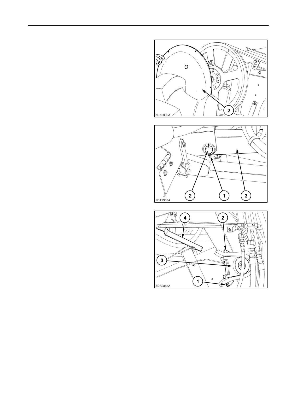
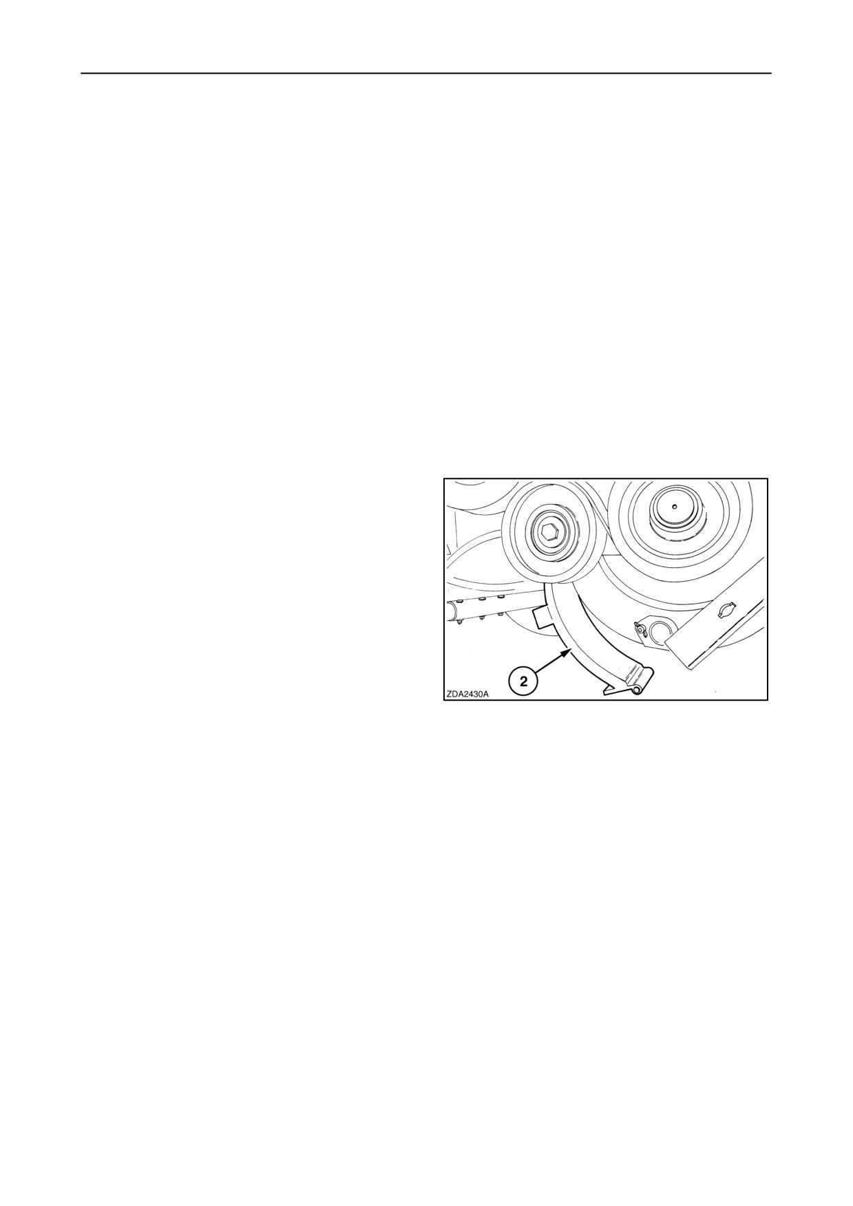
8. Remove shielding 2 of the pulley.
43
9. Remove the cotter pins 1 and pins 2, the safety
latch 3 and washers from both cylinders.
NOTE: Be careful, the cylinders are heavy.
44
10. Unscrew bolt 1 and remove keys 2 and bracket
halves 3 on both sides.
11. Move the tractor slowly forward while slightly
lowering the straw elevator.
NOTE: Be careful with header height sensor lever 4
while driving forward.
45
3-40
SECTION 3 - FIELD AND SITE OPERATION
Installation
1. Move the tractor slowly backwards, to attach the
straw elevator onto the combine.
NOTE: Mind the header height sensor lever while
attaching the straw elevator.
2. Install bracket halves, keys and install the bolts
(Metric 6) on both sides.
3. Install the hydraulic cylinders with the safety
latch(es), washers, pins and cotter pins.
46
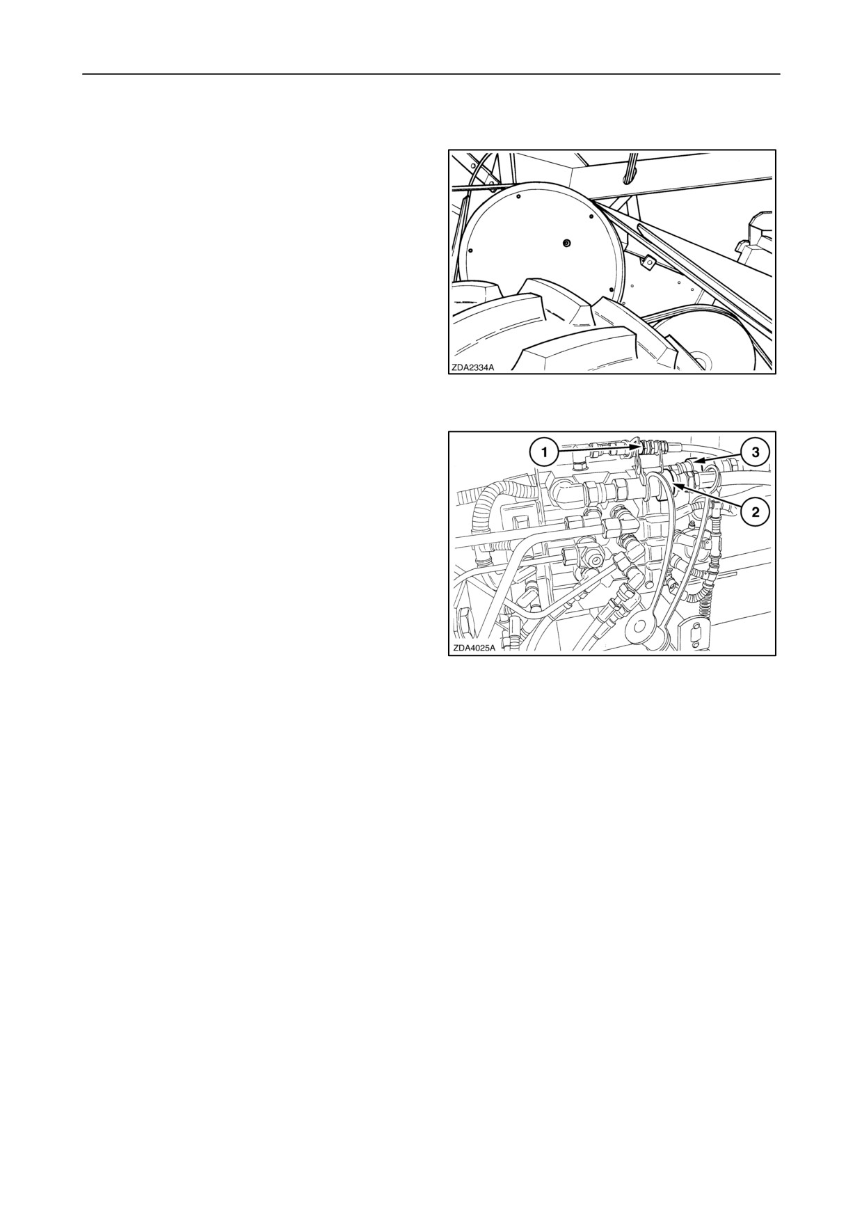
4. Install the shielding of the pulley and the drive belt
on the right-hand side.
5. Connect first hydraulic quick-coupler 3 and final
quick-coupler 2 and 1.
6. Close the shielding.
47
7. Connect the electrical cables.
8. Close the stone trap.
3-41
SECTION 3 - FIELD AND SITE OPERATION
STONE TRAP
The stone trap must be cleaned out at least once a
day, and more often in damp crop or stony conditions.
CAUTION
Disengage the threshing mechanism, lift the header
to its maximum height, place the header safety latch
over the cylinder rod and stop the engine.
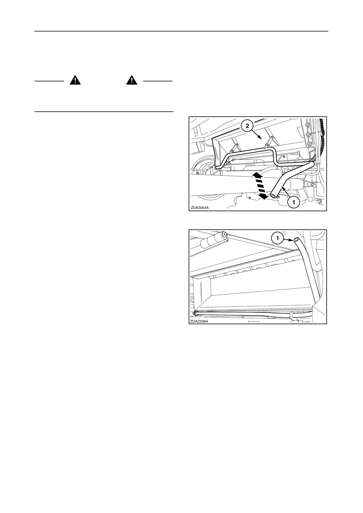
To clean out the stone trap, swing lever 1 upwards as
shown. This will open stone trap front cover 2.
48
When the stone trap is completely clean, close it by
moving lever 1 completely downwards.
49
3-42
SECTION 3 - FIELD AND SITE OPERATION
THRESHING
Anti-dust plate
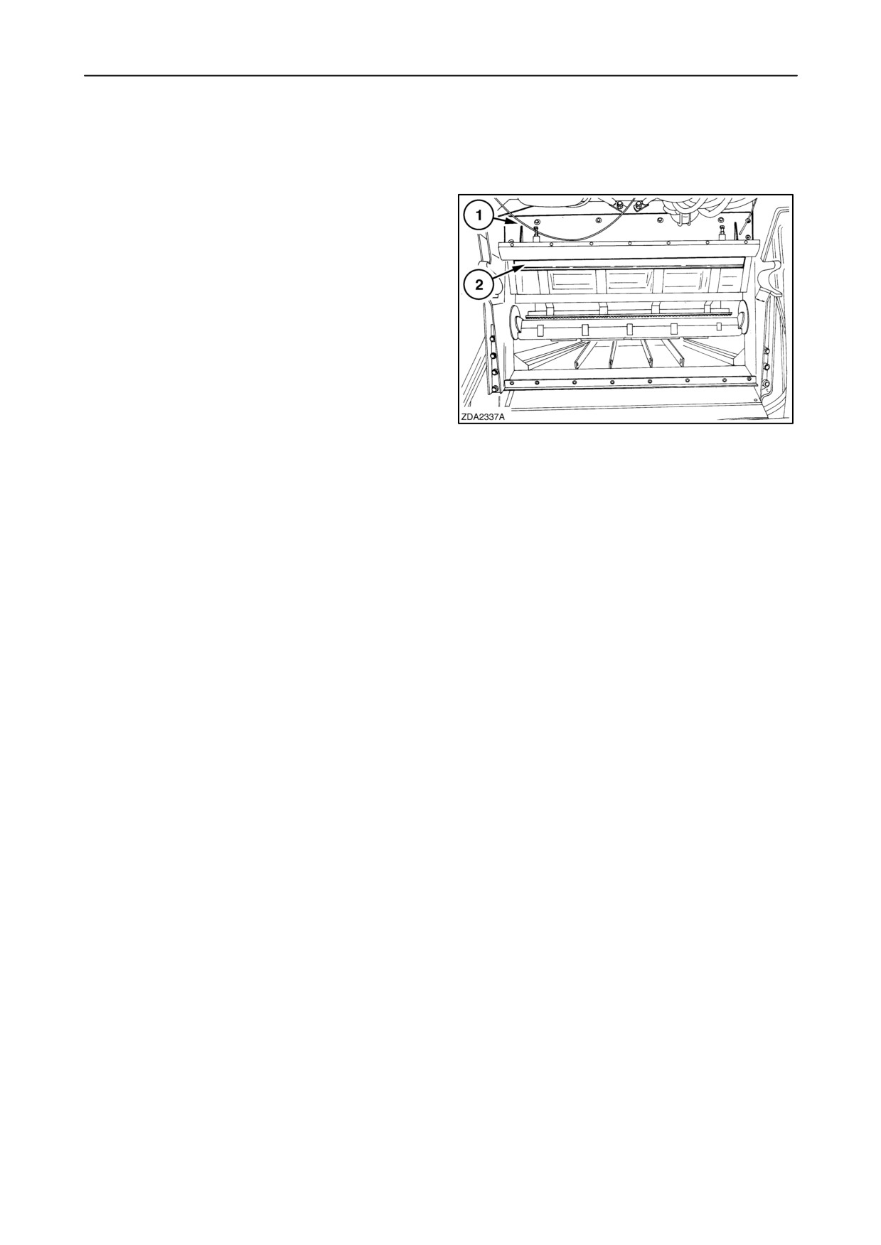
An anti-dust plate is fixed to cover 1 in front of the
drum. The lower part of the plate is adjustable. Refer
to
“SECTION
4
-
LUBRICATION AND
MAINTENANCE” ; paragraph: “Threshing” ; headed:
“Anti-dust plate”.
Remove anti-dust plate 2 and the anti-wrap shields
on both sides of the drum in maize/ sunflowers.
50
Drum and concave
PARAMETERS
Parameters for selecting the drum speed and
concave clearance are:
- Type of crop
- Crop maturity and variety
- Moisture content
- Volume of straw and grain
- Weed contamination
FUNDAMENTALS OF ADJUSTMENTS
Maximum drum speed and minimum concave
clearance give maximum threshing effect.
If grain is damaged or straw is chopped excessively,
reduce the drum speed and/or increase the concave
clearance.
If grain is not fully separated from the ears, increase
the drum speed and/or decrease the concave
clearance.
If plugging or wrapping occurs, increase the drum
speed.
3-43
SECTION 3 - FIELD AND SITE OPERATION
DRUM SPEED
The drum speed is adjustable electro-hydraulically
from the operator’s platform and can be read from the
InfoViewt monitor.
NOTE: It’s only possible to change the drum speed
with the threshing mechanism engaged.
IMPORTANT: To protect the drum variator belt:
• Never work with a minimum drum speed.
• Immediately
disengage
the
threshing
mechanism when a drum blockage occurs.
DRUM BLOCKAGE
Should the drum become blocked, proceed as
follows:
1. Clean the header and the straw elevator by using
the reverser. Refer to paragraph “Header and
straw elevator reversing system” of this Section.
2. Lower the drum, beater and rotary separator
concave to its lowest position and try to unblock
by engaging the threshing mechanism.
NOTE: When engaging the threshing mechanism,
the engine speed start automatically at 1500 rpm.
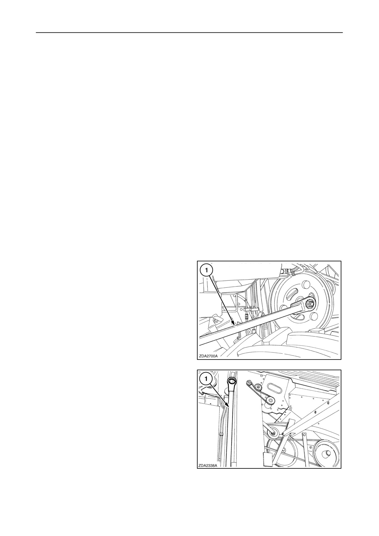
3. If this is ineffective, remove part of the slug and
try to unblock the drum by using the drum socket
wrench 1. (only when the standard drum variator
is fitted).
NOTE: To engage the threshing mechanism at high
engine rpm, hold the engine throttle rocker switch in
the increase position while the thresher is engaged.
51
The drum socket wrench 1 is located at the back
of the grain elevator.
52
3-44
SECTION 3 - FIELD AND SITE OPERATION
CONCAVE CLEARANCE
The concave clearance is adjustable electrically from
the operator’s platform if the field mode is selected
(road / field mode tumbler switch) and can be read
from the InfoViewt monitor.
IMPORTANT: To ensure that the concave clearance
that is displayed on the InfoViewt monitor is correct,
always adjust the concave clearance from the
maximum clearance to the desired clearance.
Adjustment is achieved with the drum concave
clearance control rocker switch.
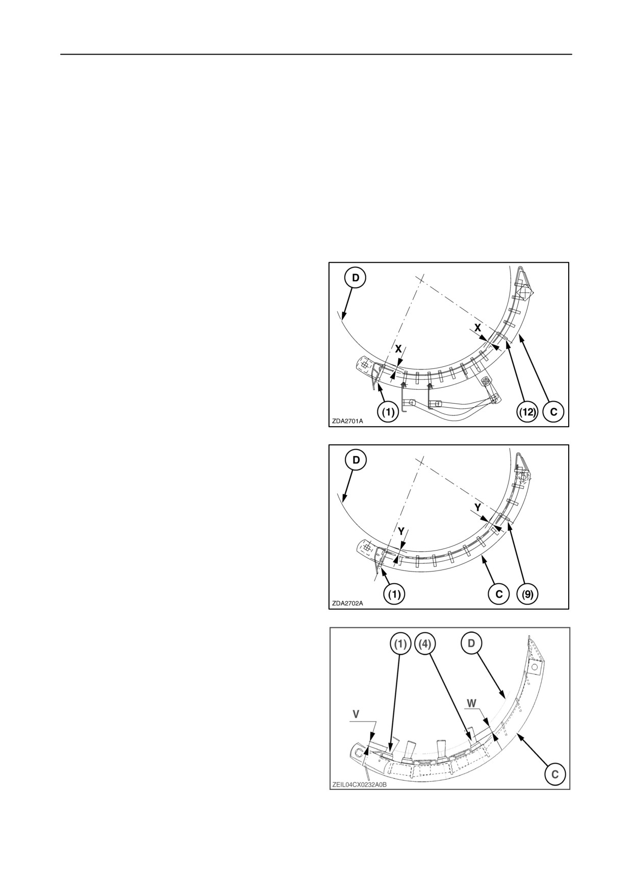
Basic settings:
• Small grain concave
When the combine is shipped from the factory, with
the small grain concave installed
(for wheat),
concave C is set parallel to drum D (front and rear)
calibrated with a clearance X of 10 mm (3/8”) at the
first (1) bar and 10 mm (3/8”) at the twelfth (12) bar.
53
• Maize concave
When the combine is shipped from the factory, with
the maize concave installed (for maize), concave C
is set parallel to drum D (front and rear) calibrated
with a clearance Y of 25 mm (126/128”) at the first (1)
concave bar and 25 mm (126/128”) at the ninth (9)
concave bar.
If excessive grain damage is experienced when
harvesting maize, increase the concave clearance Y.
54
• Rice concave
If a rice concave is installed, concave C is set to drum
D (front and rear) calibrated with a clearance V of 17
mm (2/3”) at the first (1) concave bar and with a
clearance of 22 mm (7/8”) at the fourth (4) concave
bar.
NOTE: If excessive grain damage is experienced,
increase the concave clearance.
55
3-45
SECTION 3 - FIELD AND SITE OPERATION
Drum and concave type of use
When harvesting cereals, it is advisable to use a
standard or universal drum and a cereals concave.
When harvesting maize, a standard or universal
drum and a maize concave should be installed.
When harvesting rice, a universal drum with peg tooth
bars and a rice concave should be installed.
If needed, the concave and / or universal drum can be
converted for harvesting other crops
(e.g. when
switching from cereals to maize).
Replacement of the drum concave
To remove the drum concave, proceed as follows:
1. Park the combine on a level surface and check if
the cleaning shoe is level (if self levelling cleaning
shoe).
2. Close the concave completely with the drum con-
cave clearance rocker switch in the cab.
3. Detach the straw elevator. Refer to
“Straw
elevator
- Removal and Installation” of this
Section.
4. Open the stone trap and the pivot plate.
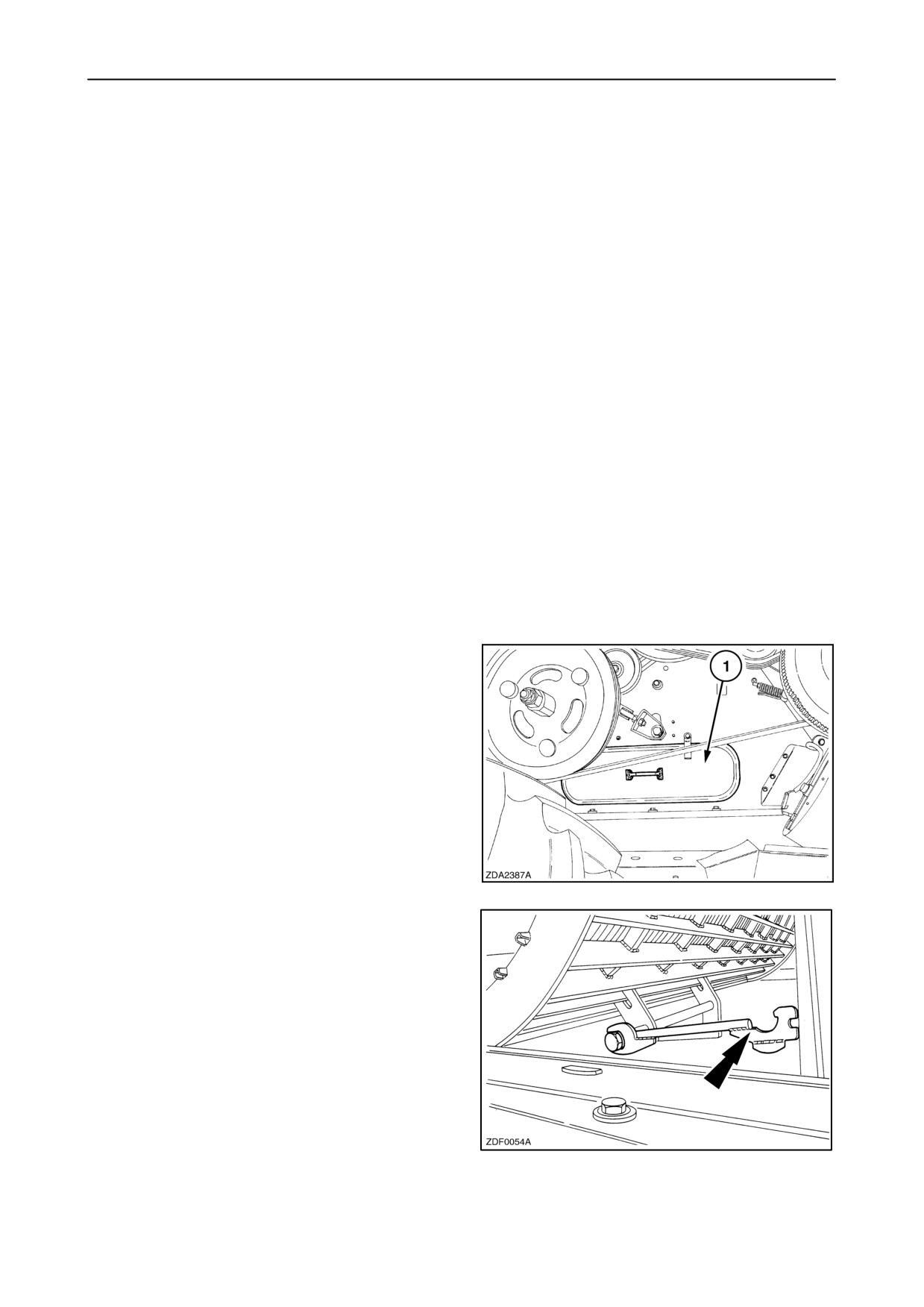
5. Remove grain pan access covers 1 left and right.
56
6. In case a small grain concave is installed, close
the de-awning plates by using the special tool
located at the left-hand side of the straw elevator.
57
3-46
SECTION 3 - FIELD AND SITE OPERATION
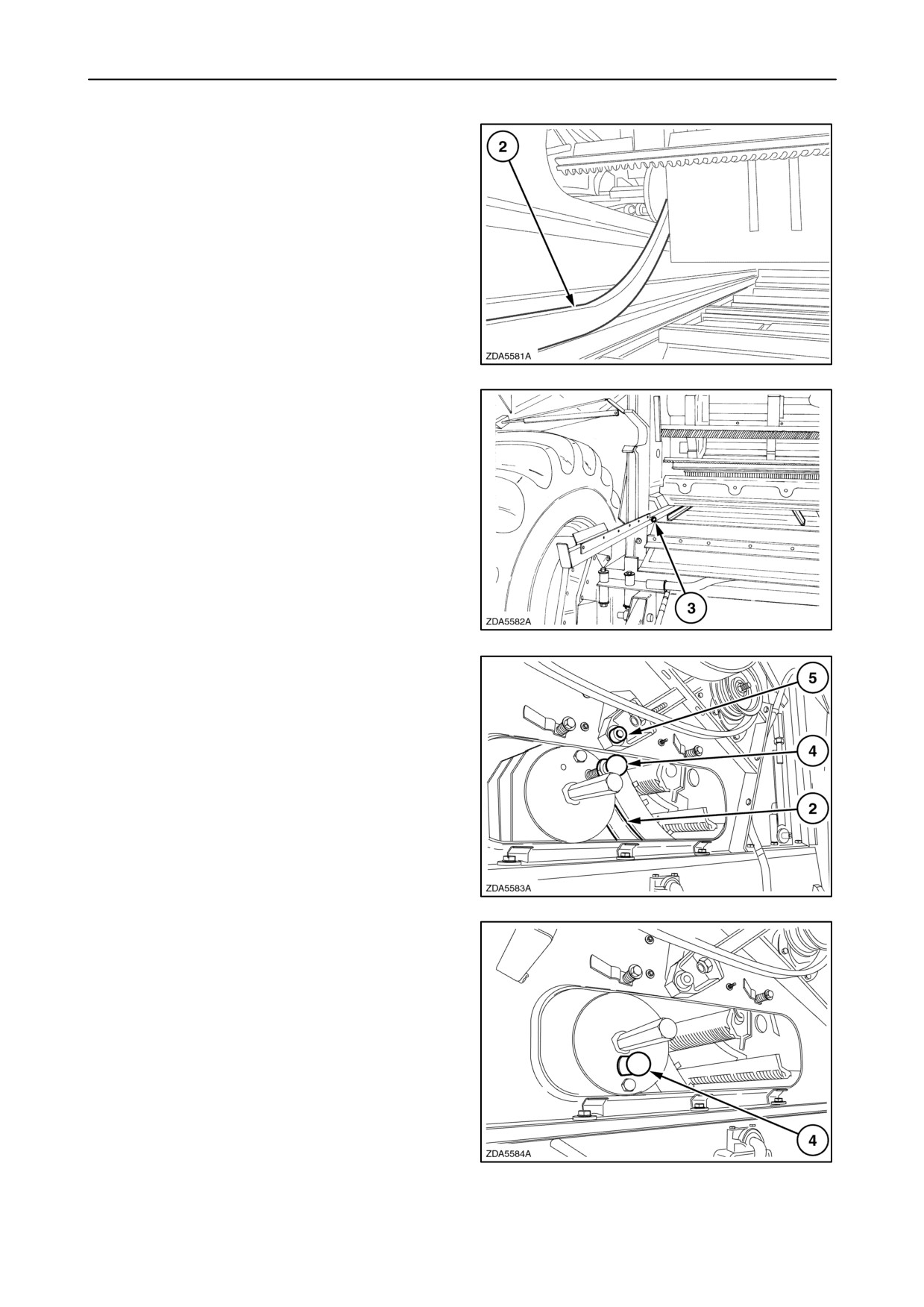
7. To install the special tool, proceed as follows on
both sides.
• Bring support 2 with eccentric disc to the inside of
the threshing frame. Insert the eccentric disc
through the grain pan access hole and turn the
eccentric disc so it fits into the grain pan access
hole.
58
• Install bolt 3 to attach the special tool supports on
both sides of the frame.
59
8. Pull out pin 4 and turn the eccentric disc so that
support 2 is installed in the upper position at the
back and secure with pin 4.
9. Lower the concave with the drum concave
clearance rocker switch in the cab until the
concave touches the special tool.
10. Remove bolt 5 at the rear of the concave on both
sides.
60
11. Pull out pin 4 and turn the eccentric disc 180
degrees (from the front hole to the rear hole) to
lower the support and the concave. Secure with
pin
4 when the special tool is in it’s lowest
position.
61
3-47
SECTION 3 - FIELD AND SITE OPERATION
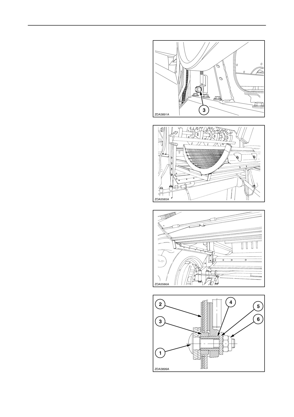
12. Loosen nut 3 to remove the bolt at the front of the
concave on both sides.
NOTE: Lift the concave at the front to allow the rear
of the concave to pass underneath the drum.
62
13. Pull out the concave.
14. Now is it possible to remove the concave with an
adequate lifting device.
63
To install the drum concave, proceed as follows:
1. Bring the concave into the special tool supports,
using an adequate lifting device.
2. Lift up the front of the concave and push it parallel
in to his position (end of the special tool supports)
64
3. At the front, install spacer 2 between the concave
and the frame, bushings 3 and 4 on both sides.
4. Install bolt 1, washer 5 and tighten locknut 6 to a
minimum torque of 375 Nm. (277 ft.lbs)
65
3-48
SECTION 3 - FIELD AND SITE OPERATION
IMPORTANT: Be sure that bushing 3 is centred in
spacer 2.
66
5. Pull out pin 4 and turn the eccentric 180 degrees
back until the upper position.
Secure with pin 4.
NOTE: It is not necessary to do this handling on both
sides at the same time.
67
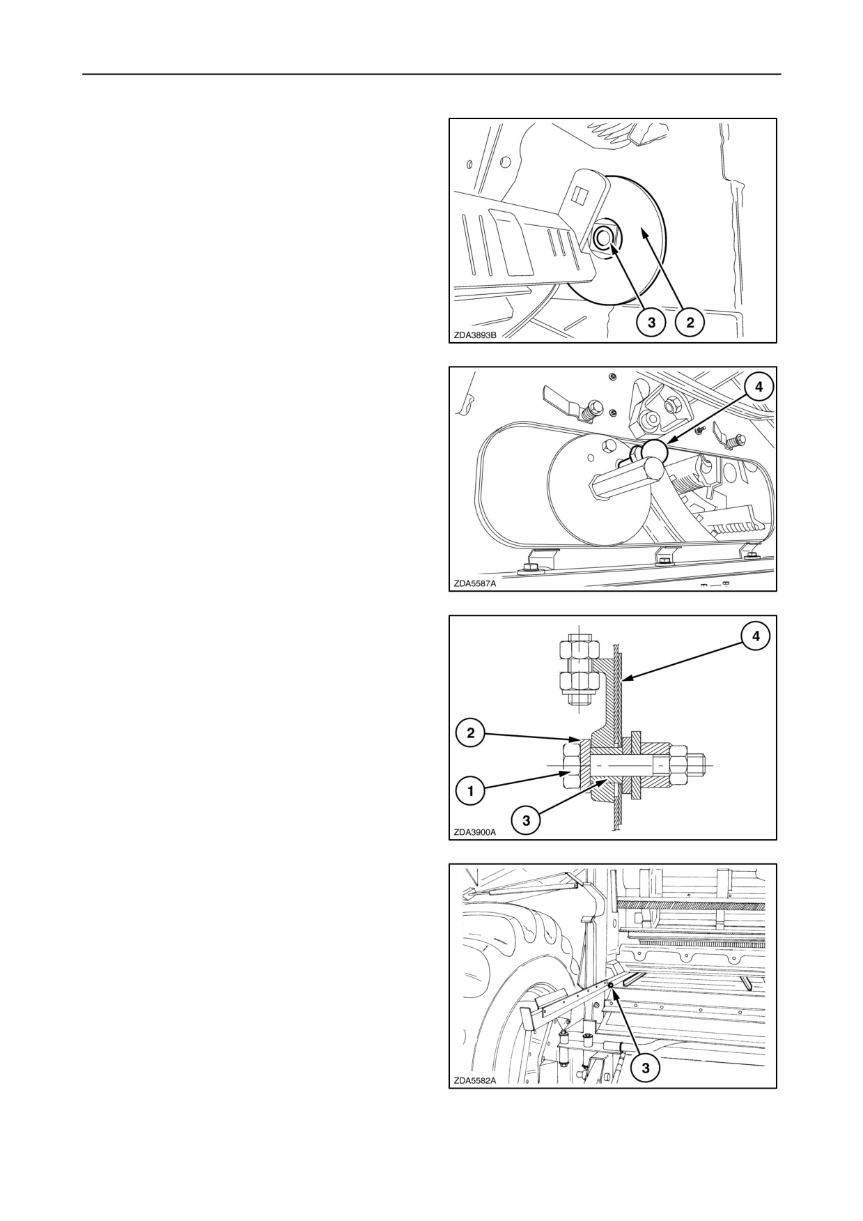
6. Install bolt 1, washer 2, bushing 3 and spacer 4
at the rear (left and right).
7. Tighten bolt 1 to a minimum torque of 375 Nm.
(277 ft.lbs)
IMPORTANT: Be sure that bushing 3 is centred in
spacer 4.
68
8. Loosen bolt 3 on both sides and remove the
special tool supports completely.
69
3-49
SECTION 3 - FIELD AND SITE OPERATION
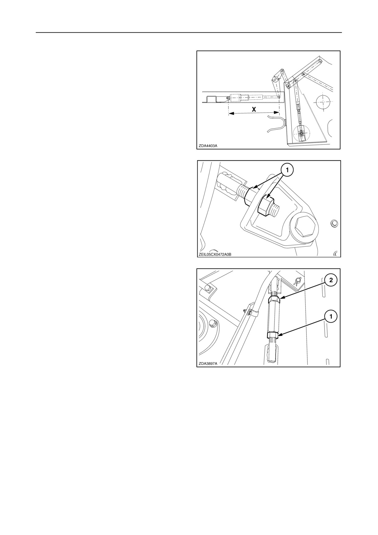
9. Adjust dimension “X” (”X” = distance from centre
to centre of the actuator)
“X” = 539 - 541 mm (21-1/4” - 21-19/64”) for a
small grain or a heavy duty moderate/universal
concave with InfoViewt monitor read out at 10.
“X” = 504 - 506 mm (19 - 27/32” - 19 - 59/64”) for
a maize concave with InfoViewt monitor read
out at 25.
“X” = 516 - 518 mm (20 - 5/16” - 20 - 3/8”) for a
rice or grass seed concave with InfoViewt moni-
tor read out at 17.
70
10. The settings can be obtained by adjusting the
nuts (1) and (2) (fig. 71 and 72) on both sides of
the concave. (front and the back even)
After adjusting tighten nuts (1) and (2) to a torque
of
170 - 190 Nm. (125 - 140 ft.lbs)
IMPORTANT: After installing a small grain concave
push the actuator completely out (= minimum clear-
ance concave to the drum)
Check if the minimum distance of the concave to the
drum with regard to the rasp bar on the largest radius
is between 1-3 mm (5/128” - 1/8”) to the 7 nd bar of
the concave to avoid interference.
71
IMPORTANT: Nut 2 is foreseen with left-hand thread.
72
3-50
SECTION 3 - FIELD AND SITE OPERATION
11. Open the concave completely with the drum con-
cave clearance rocker switch in the cab.
12. Close the concave until the recommended dis-
tance between the rasp bar on the largest radius
and the concave.
For the correct distance refer to table below: ”Set-
ting of different types of concaves”: ”Real con-
cave clearance”.
NOTE: After carrying out adjustments to the con-
cave, ensure that the concave rub bars are set paral-
lel to the drum rasp bars.
13. Go to InfoViewt monitor, select in the calibration
sub-menu ”Concave position” and do the calibra-
tions. Refer to Section 2 - ”Controls, Instruments
and Operation”, paragraph: “Calibration of the
concave position”.
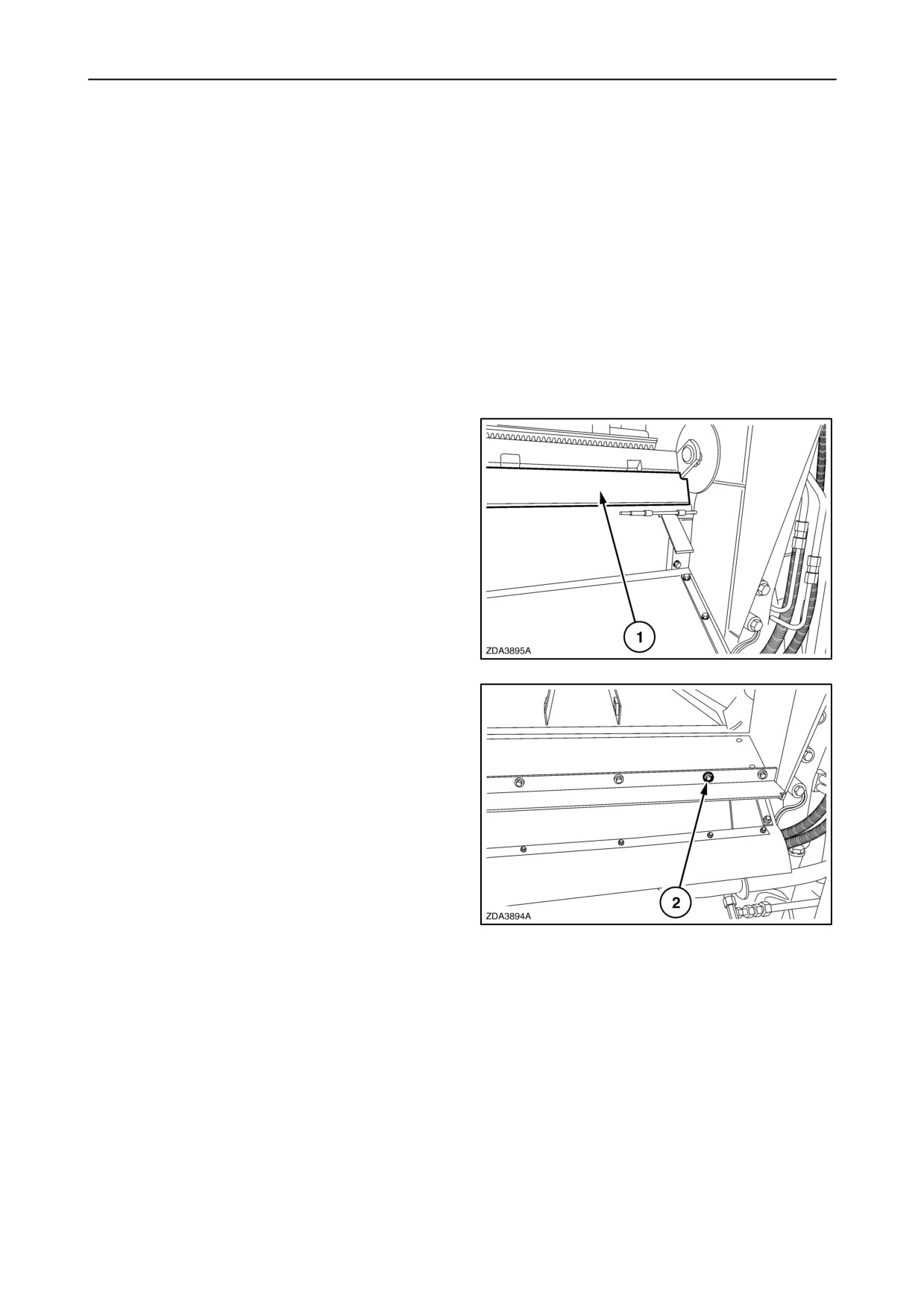
14. After installation of the concave, it is necessary to
adjust plate 1 of the pivot plate.
73
15. Adjust the plate by loosening bolts 2.
74
3-51
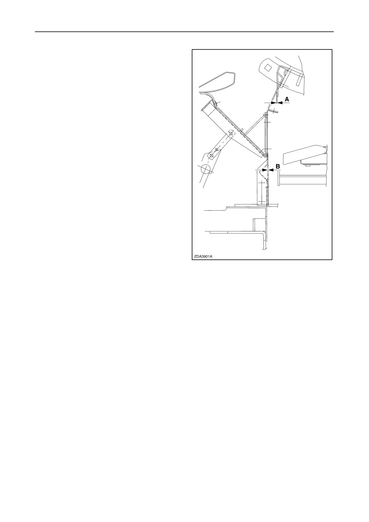
SECTION 3 - FIELD AND SITE OPERATION
16. The distance A = 2 mm (5/64”) for a small grain
and rice concave.
A = 4 mm (5/32”) for a maize concave.
IMPORTANT: This dimension A is to be measured
with prescribed standard threshing drum concave
settings and with the pivot plate in locked position.
75
17. Attach the straw elevator. Refer to ”Straw elev-
ator - Removal and Installation” of this section.
18. Close the stone trap.
19. Install the grain pan access covers on both sides.
3-52
SECTION 3 - FIELD AND SITE OPERATION
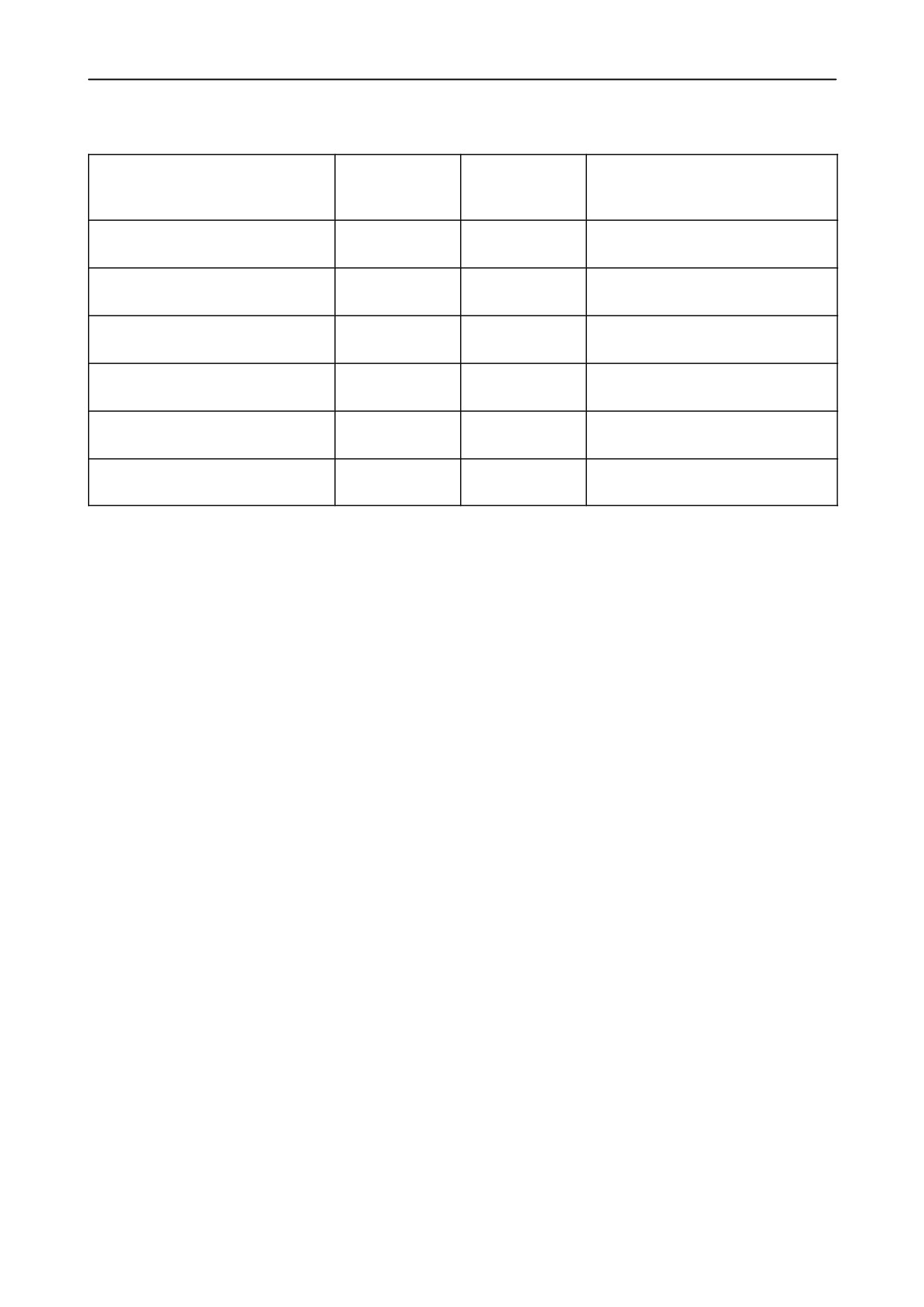
SETTING OF DIFFERENT TYPES OF CONCAVES
Concave type
Use
Concave clear-
Real concave clearance
ance read out
(Adjust with nuts 1 and 2,
fig. 71 and 72)
Small grain concave
Cereals
10 mm (3/8”)
10 mm (3/8”) to 1 st bar
10 mm (3/8”) to 12 nd bar
Heavy Duty moderate concave
Cereals
10 mm (3/8”)
10 mm (3/8”) to 1 rd bar
10 mm (3/8”) to 12 nd bar
Maize concave
Maize
25 mm (1”)
25 mm (1”) to 1 rd bar
25 mm (1”) to 9 nd bar
Heavy Duty universal concave
Cereals
10 mm (3/8”)
10 mm (3/8”) to 1 rd bar
Maize
10 mm (3/8”) to 12 nd bar
Rice concave
Rice
17 mm (2/3”)
17 mm (2/3”) to the first bar
22 mm (7/8”) to the last bar
Grass seed concave
Grass seed
17 mm (2/3”)
17 mm (2/3”) to the first bar
22 mm (7/8”) to the last bar
3-53
SECTION 3 - FIELD AND SITE OPERATION
De-awning plates
De-awning plates increase the rubbing action of the
drum and concave when threshing winter barley or
difficult to thresh crops.
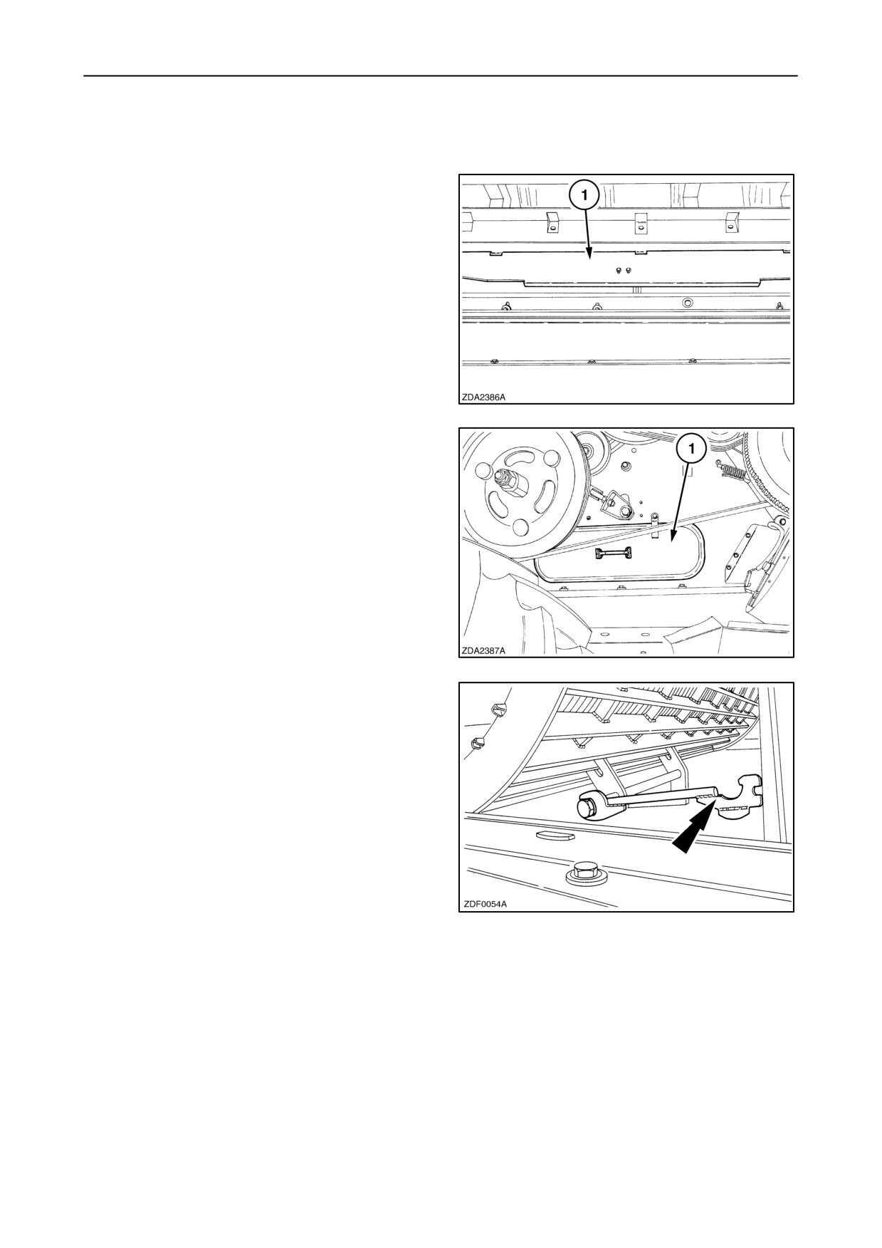
Two de-awning plates 1 are attached to the concave
with hinges and can be locked in position with a
wrench.
76
Proceed as follows:
1. Remove grain pan access cover 1 at the left-hand
side.
77
2. Close the de-awning plates, using the special tool
that is located at the left-hand side of the straw
elevator or a spanner of 30 mm. (1 - 3/16”)
The outside nut operates the front de-awning plate
and the inside nut operates the rear de-awning plate.
Only close the rear de-awning plate if really
necessary, as partially closing of the concave
inevitably means loss of separation capacity.
78
3-54
SECTION 3 - FIELD AND SITE OPERATION
SEPARATION
Beater
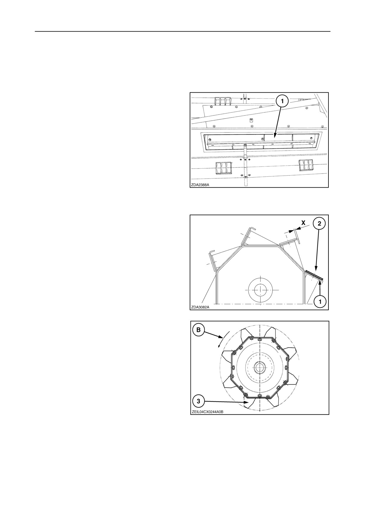
The beater, which runs at the same speed of the
drum, is accessible through inspection opening 1 in
the grain tank.
79
• Beater blades
If wear plates 1 installed on the beater, adjust this to
a distance “X” = 5 - 6 mm (3/16” - 1/4“) with
the bolts 2.
For easy adjustment, remove the beater drive belt.
80
• Beater pins
If toothed bars 3 installed on the beater, check that
these are installed alternately.
NOTE: Arrow “B” = rotation direction
81
3-55
SECTION 3 - FIELD AND SITE OPERATION
Rotary separator
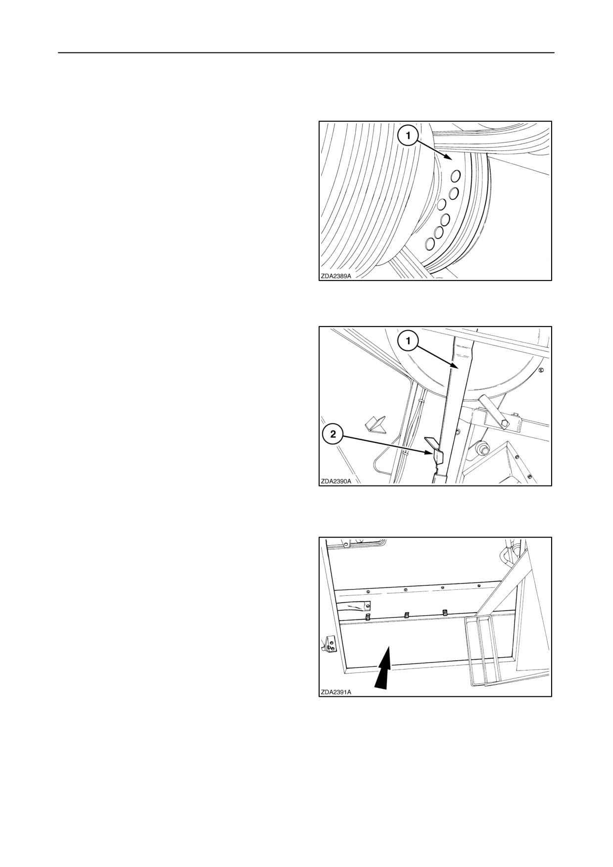
The rotary separator is driven by pulley 1 which has
a double groove for an alternative speed:
- High speed is for harvesting most of crops such
as barley, oats, rye, wheat, rice, grass seed, etc.
- Low speed is for harvesting maize, beans, peas,
soya, sunflower, oil seed rape, etc.
82
To change the speed, proceed as follows:
1. Move lever 1 out of hook 2 and upwards. This will
move the idler and loosen the belt tension.
2. Install the belt in the other grooves of both
pulleys.
3. Move lever 1 downwards and secure the lever in
hook 2 as shown.
4. Check the belt tension and adjust, if necessary
Refer to
“Section
4
- LUBRICATION AND
MAINTENANCE”, paragraph headed:
”Belts and Chains”.
83
The rotary separator is accessible through the cover,
which is situated underneath the grain tank.
84
3-56
SECTION 3 - FIELD AND SITE OPERATION
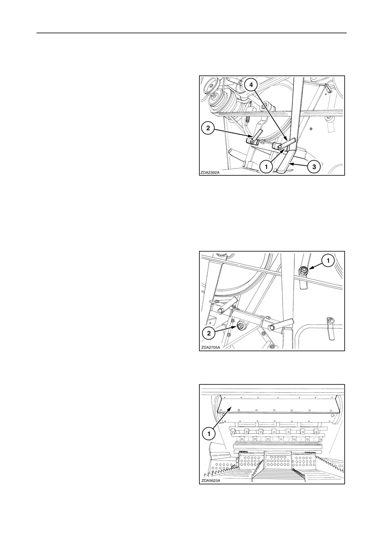
Multi-thresh system
With the multi-thresh system the beater and rotary
separator concaves can be set in two positions.
Closed position (1): Lever 3 forwards.
This position is recommended for all crops, as the
separation effect is high.
Open position (2): Lever 3 rearwards.
In this position the rubbing is less aggressive which
is recommended in brittle straw and oil rape seed.
85
If necessary, reduce the combining speed to avoid
grain losses.
Secure lever 3 with latch 4.
There is a possibility to block the concaves
(e.g. maize) with nuts 1 and 2 on both sides.
86
Straw flow beater
The function of straw flow beater 1 is to improve the
combine throughput capacity in heavy straw
conditions.
87
3-57
SECTION 3 - FIELD AND SITE OPERATION
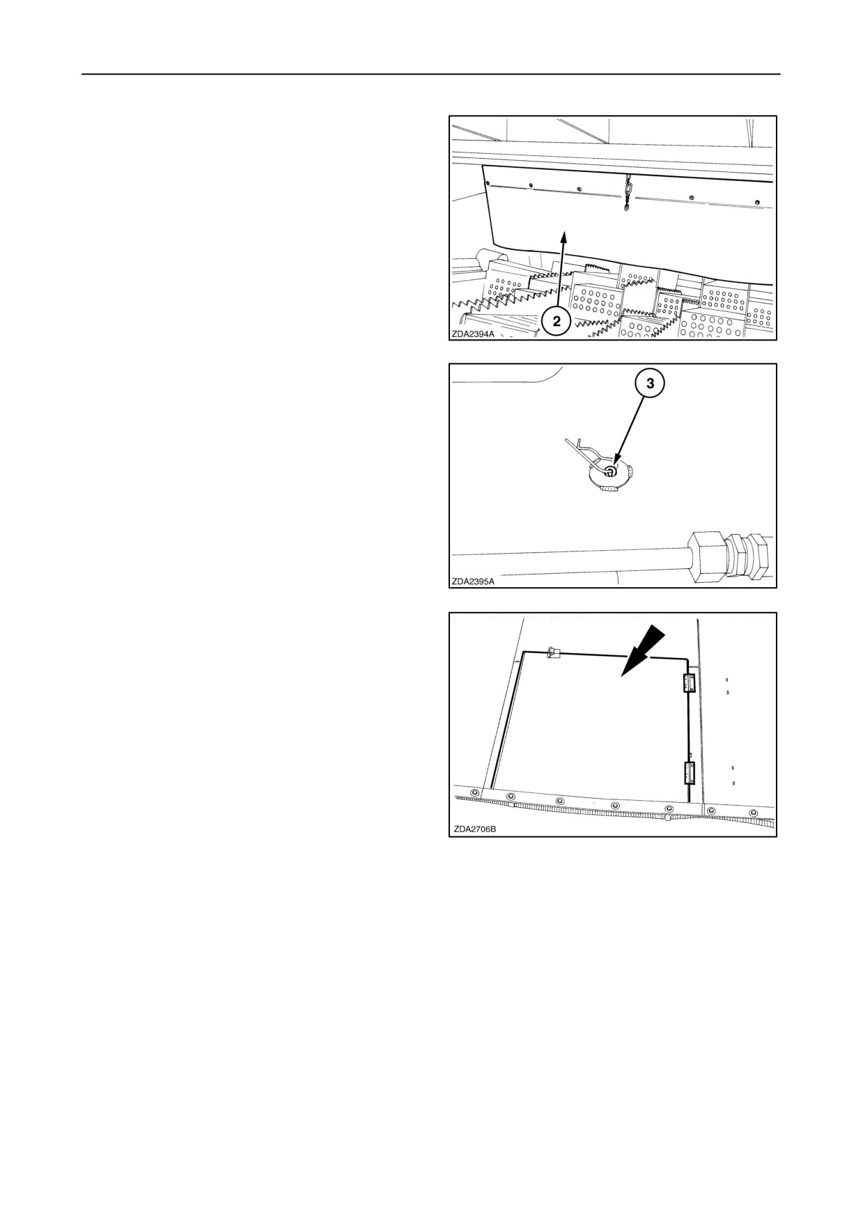
Straw retarding curtain
A straw retarding curtain 2 is positioned at the rear of
the straw flow beater and above the straw walkers to
prevent the grain from being thrown out of the
combine by the rotary separator.
88
Curtain 2 (fig. 88) can be raised with chain 3 to
improve the material flow in heavy crop conditions.
89
Straw walkers
Open the cover to gain access to the straw walkers.
90
3-58
SECTION 3 - FIELD AND SITE OPERATION
CLEANING SYSTEM
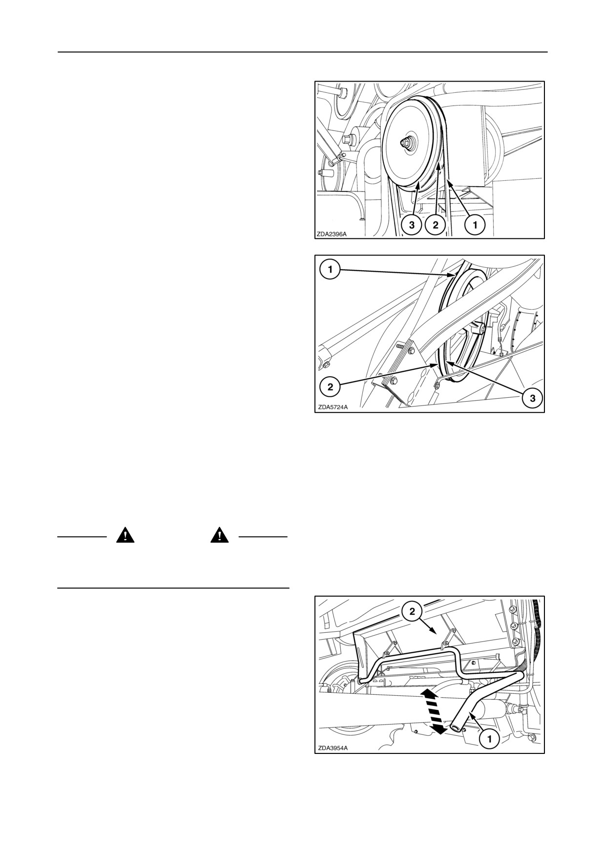
Cleaning shoe
The drive pulley has a double groove for an
alternative speed of the cleaning shoe drive:
91
• Low speed (groove 3) is for harvesting brittle
crops and all kinds of small seeds (rape seed,
grass seed, sunflower, etc.)
• High speed (groove 2) is the factory-set speed,
which is suitable for most crops.
Fig. 91: Self-levelling cleaning shoe
Fig. 92: Fixed cleaning shoe
92
Removable grain pan (if installed)
It’s possible to remove the grain pan in wet threshing
conditions in order to clean it.
GRAIN PAN REMOVAL
1. Raise straw elevator completely.
DANGER
Install the header safety latch on the header lift
cylinder before working underneath the straw
elevator.
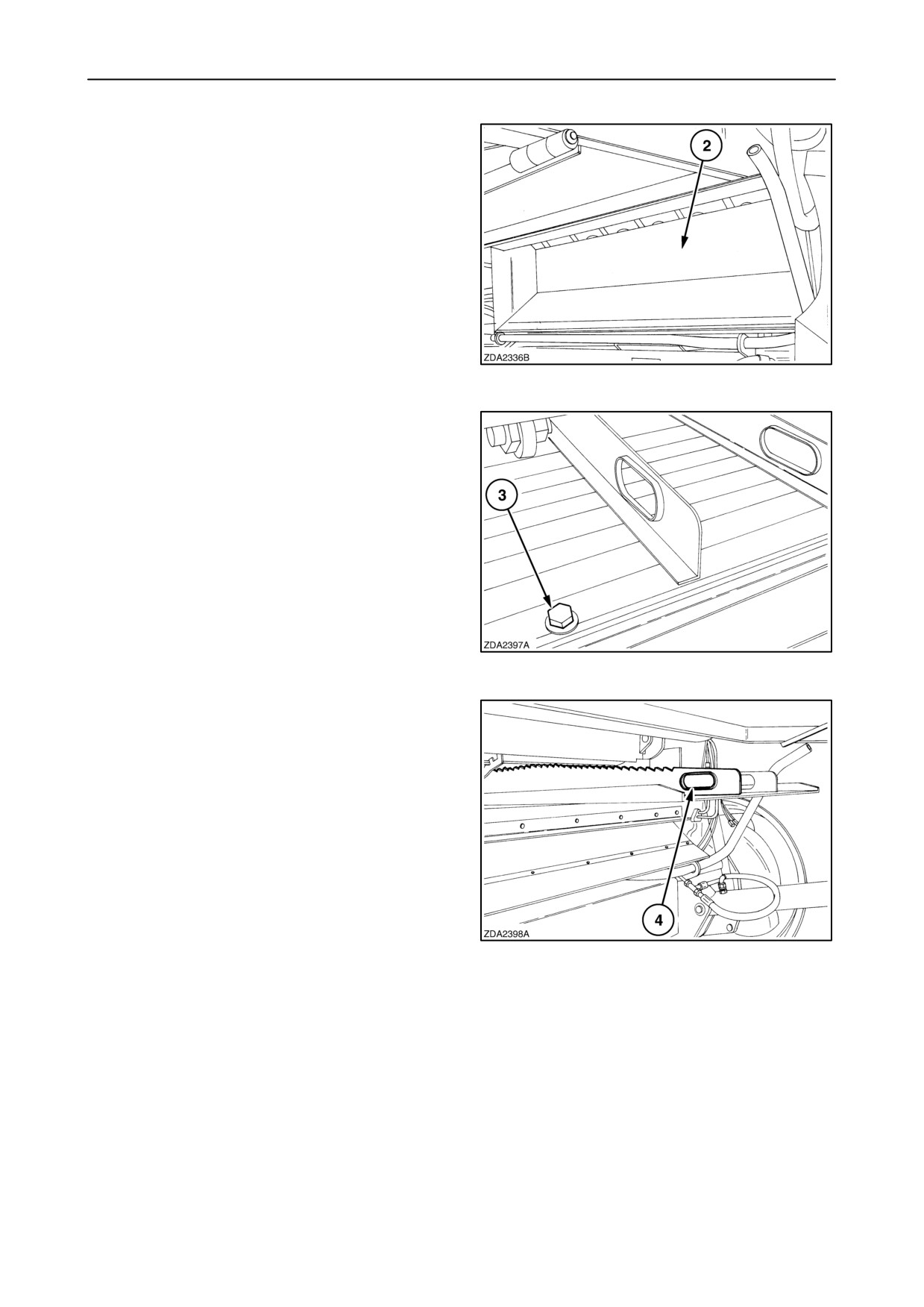
2. Swing lever 1 upwards as shown. This will open
stone trap front cover 2.
93
3-59
SECTION 3 - FIELD AND SITE OPERATION
3. Open pivot plate 2 (slide the left and right lever
towards the centre of the stone trap).
94
4. Loosen two bolts 3 at the front of each grain pan
section.
NOTE: The grain pan consists of two sections.
95
5. Take one grain pan section at grip 4, lift it up and
pull it towards the front to remove it. Proceed the
same for the second grain pan section.
96
3-60
SECTION 3 - FIELD AND SITE OPERATION
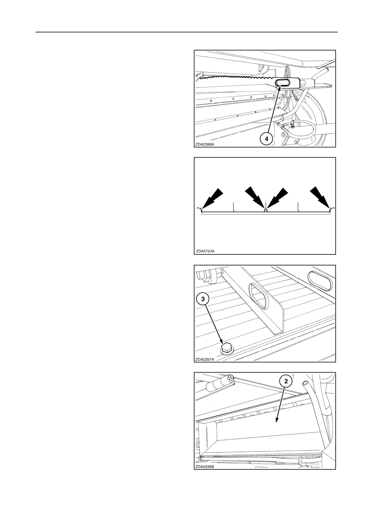
GRAIN PAN INSTALLATION
1. Slide both grain pan sections into the cleaning
shoe by using hand grip 4.
97
IMPORTANT: Check if the sealing on both sides of
the grain pan are installed at the right direction as
shown.
98
2. Tighten bolts 3.
99
3. Close pivot plate 2 and the stone trap.
100
3-61
SECTION 3 - FIELD AND SITE OPERATION
Sieves
SIEVE OPENINGS
IMPORTANT: To adjust the sieves to the desired
clearance, move always the lever(s) (or if electrical by
using the switch from the cab) from the closed
position to the desired opening.
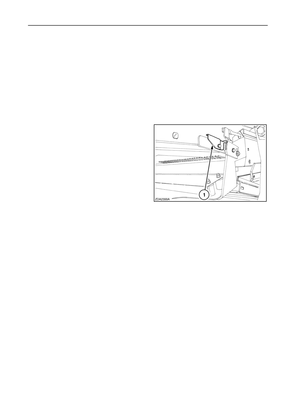
• Presieve
Adjust the opening of the presieve, according to the
grain size, with the lever 1 on the right-hand side at
the back of the shaker shoe.
A 6 mm (1/4”) opening is the recommended position
for most cereal crops and sunflower
(New Holland 1-1/8”).
When operating in damp conditions, a larger opening
can be recommended to avoid plugging of the
presieve.
101
For small seeds, a 3 mm (1/8”) opening can be
chosen.
When harvesting maize a presieve HC 1-5/8”, can be
used.
NOTE: Adjusting the presieve is always manually.
3-62
SECTION 3 - FIELD AND SITE OPERATION
• Upper and Lower sieve
Adjust the openings of the upper and lower sieve,
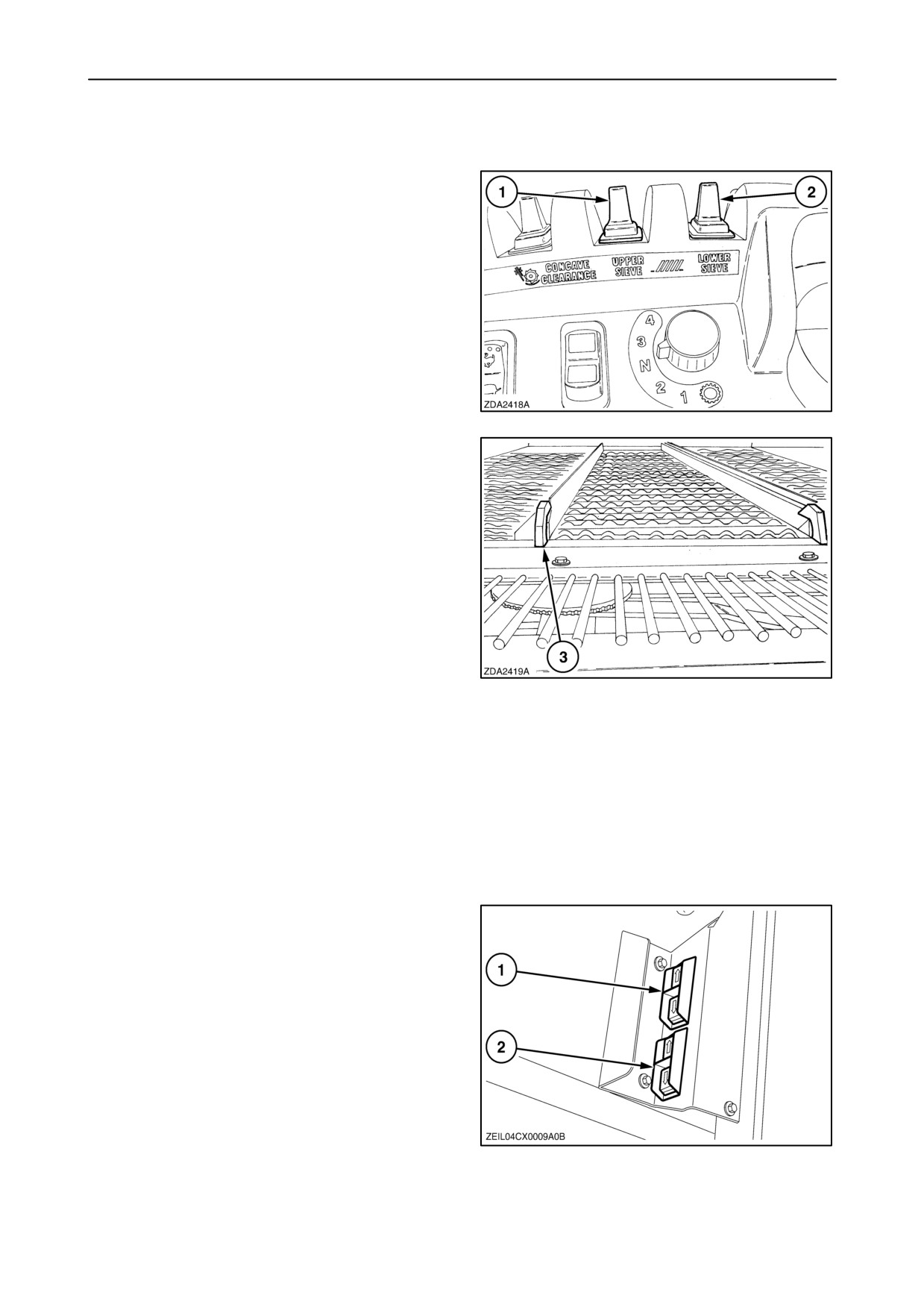
according to the grain size, with the levers at the rear
of the sieves or electrical (if installed) with switches
1 or 2 from the operator’s platform.
A ”pop-up” screen appears on the InfoViewt monitor
when changing the sieve settings.
NOTE: To prevent damage on the sieves when
closing the sieves, they open first 5 mm, afterwards
they close to the selected value.
102
The upper and lower sieve(s) are equipped with a
sieve opening indicator 3.
The rear part (extension) of the upper sieve
(HC 1-1/8”) can be adjusted separately. It may be
necessary for the rear part to be opened a few
millimetres more than the sieve opening to prevent
loss of the returns, particularly when harvesting
wheat.
When harvesting maize, keep the upper sieve
(HC 1-5/8”) closed as much as possible to sieve all
the grain and to prevent the maize cobs from passing
through the sieve and entering the grain tank.
103
IMPORTANT: On the CX800 models the upper and
lower sieve consists of two sieve halves. It is
important that the both sieves (left and right) has the
same opening. To adjust the left and right-hand sieve
halves (upper and lower sieve) and to obtain the
same opening, refer to SECTION 4 - “LUBRICATION
AND MAINTENANCE”, paragraph: “Cleaning”.
NOTE: It is also possible to adjust the sieves at the
rear. Two rocker switches are located at the inside of
the straw hood (left-hand side) to adjust the lower
sieve (switch 2) and upper sieve (switch 1).
104
3-63
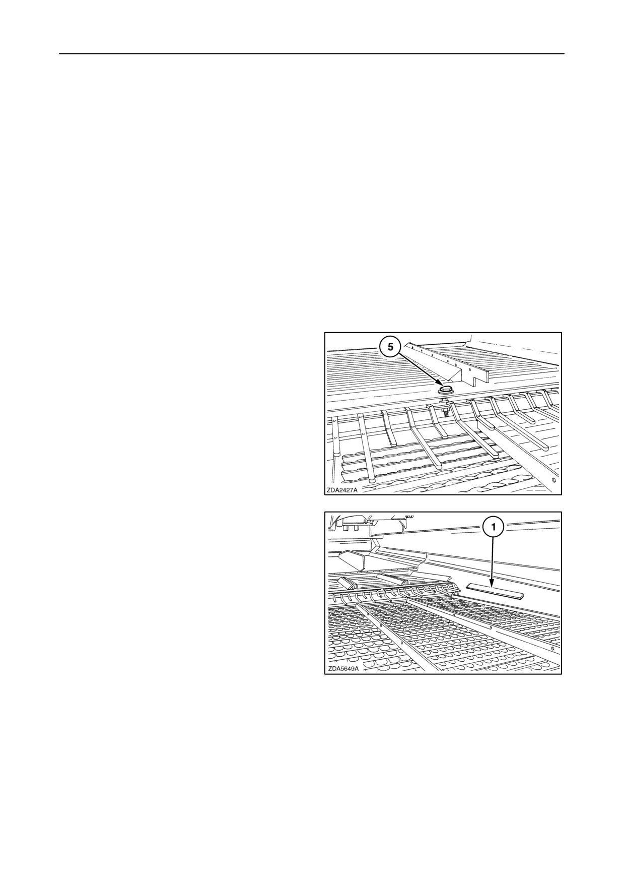
SECTION 3 - FIELD AND SITE OPERATION
SIEVE POSITION
Only the upper sieve can be installed at the rear in two
positions, the upper position and the lower position.
The upper sieve (HC 1-1/8”) is normally fitted in the
lower position.
The upper position is recommended when harvesting
maize. Working with the upper sieve (HC 1-5/8”) in
the upper position requires a canvas that is fitted at
the back on the sieve.
For wheat and maize (if necessary) the same lower
sieve (New Holland 1-1/8”) can be used.
SIEVE REMOVAL
Proceed as follows:
• Presieve
1. Remove two bolts 5.
105
2. Pull out of the presieve, using supports 1.
106
3-64
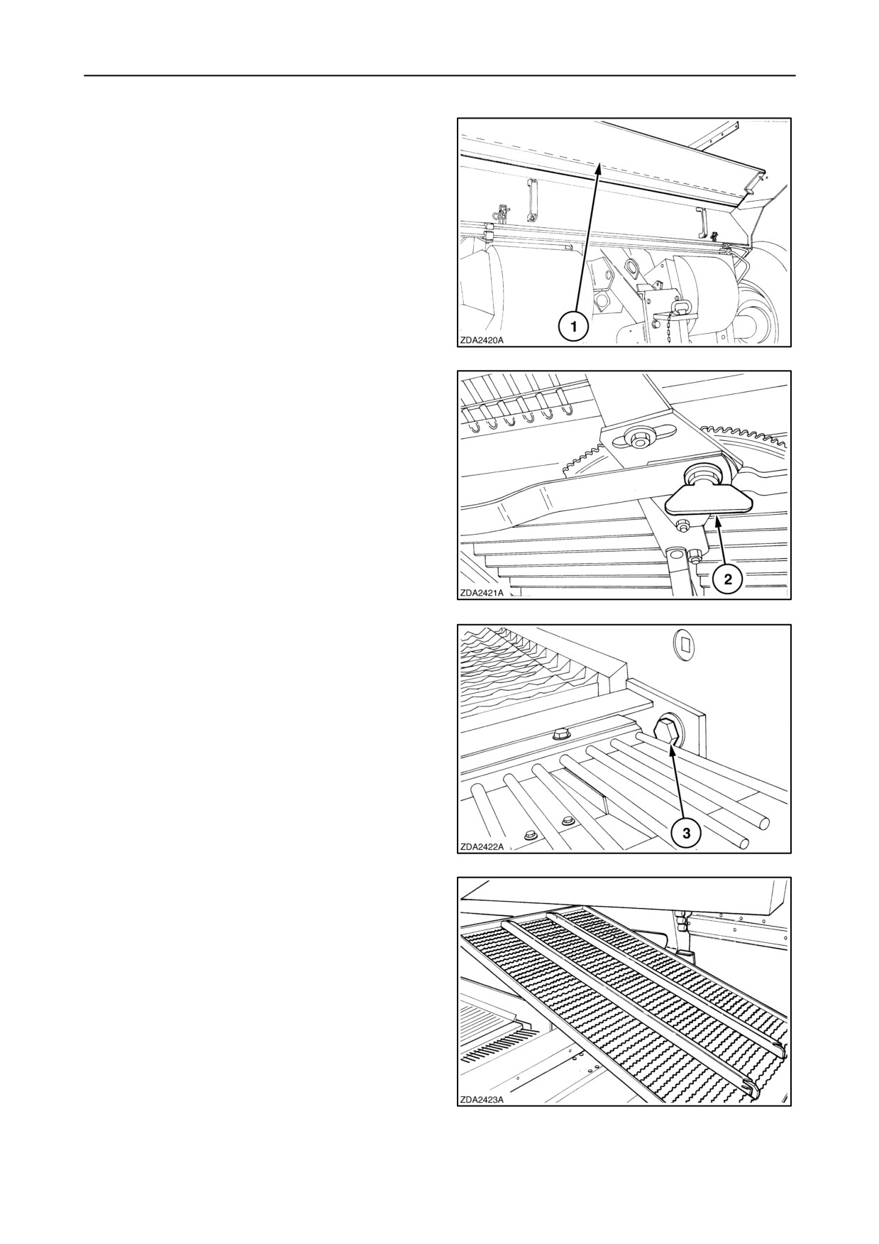
SECTION 3 - FIELD AND SITE OPERATION
• Upper sieve
1. Lower deflector plate 1 of the chaff-blower.
107
2. Disconnect bracket(s) 2 in case remote sieve
control is installed.
108
3. Remove bolts 3 on both sides.
In case of two sieve halves (CX800 models),
remove also the central bolt.
109
4. Remove the upper sieve(s).
110
3-65
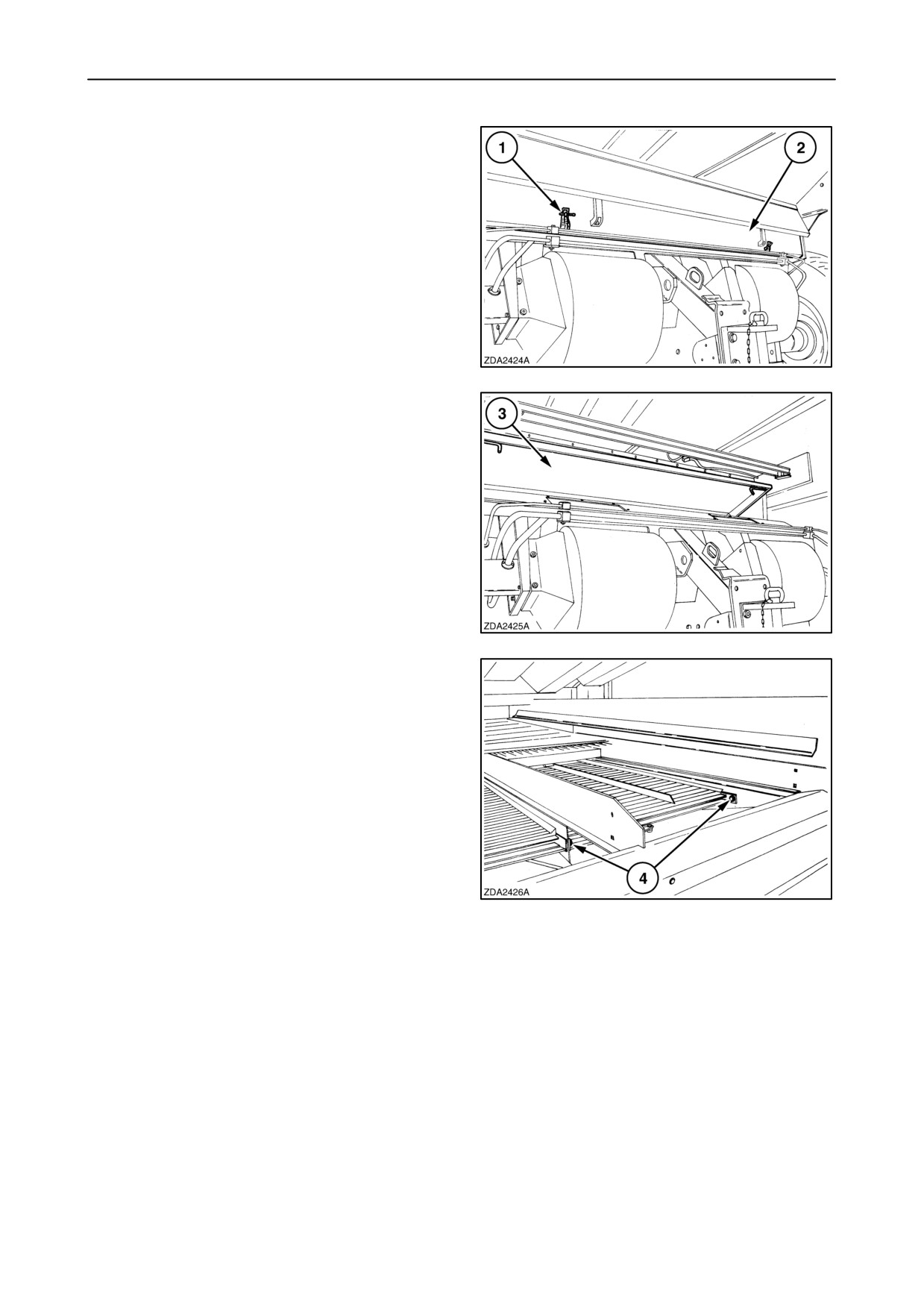
SECTION 3 - FIELD AND SITE OPERATION
• Lower sieve
Remove first the upper sieve(s).
1. Remove two hair pins 1 to open the locks.
2. Remove box 2 completely.
111
3. Open lower access plate 3.
4. Disconnect bracket 2 (fig 108) in case electrical
sieve control is installed.
112
5. Remove bolts 4 on both sides and remove the
lower sieve. Adjust the shaker shoe position by
hand if the grain loss sensor prevents the removal
of the sieve.
113
3-66
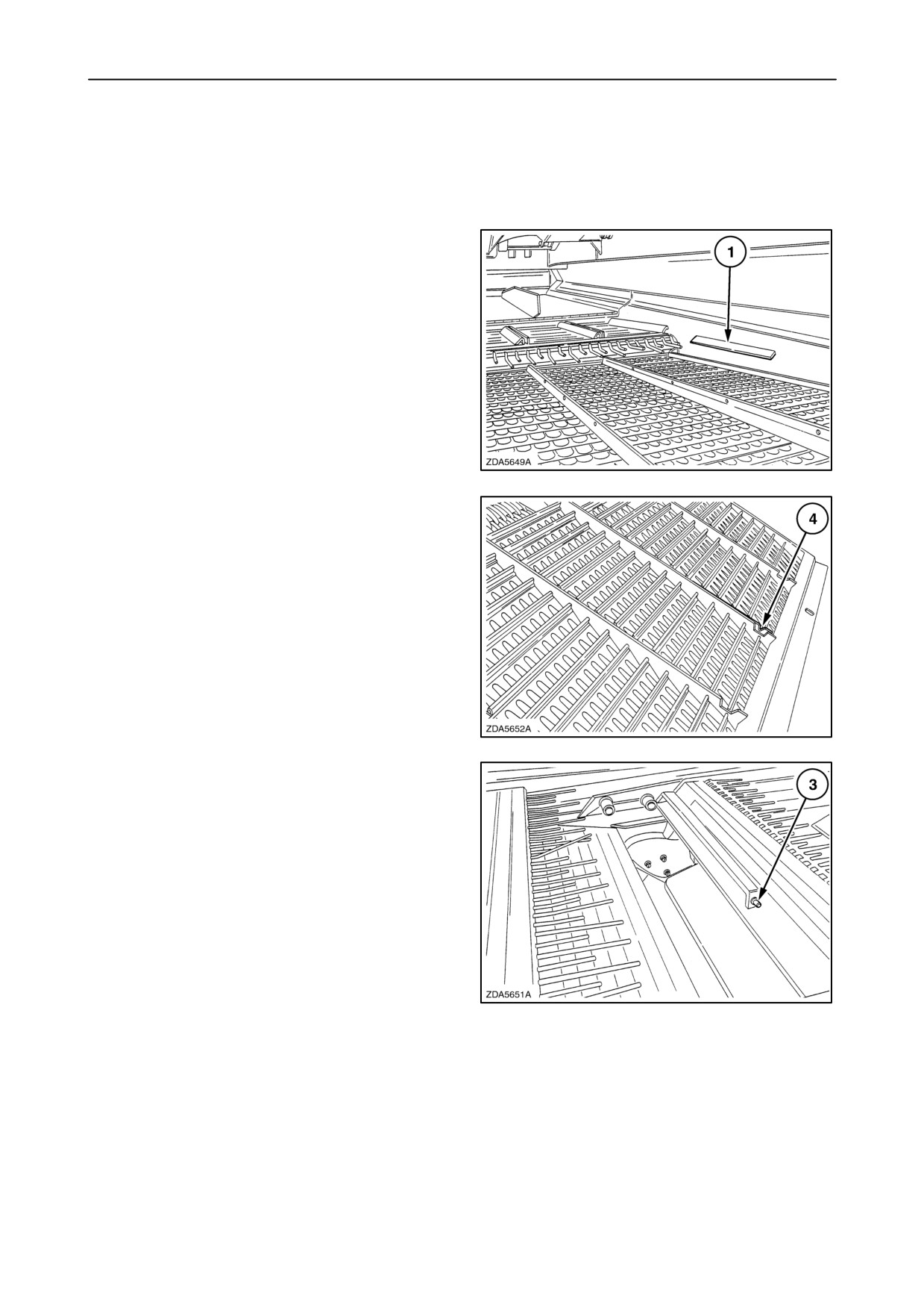
SECTION 3 - FIELD AND SITE OPERATION
SIEVE INSTALLATION
Presieve
Proceed as follows:
1. Place the presieve on supports 1 on both sides
of the shaker shoe and slide the presieve
completely into its place.
114
2. Move the presieve forwards/rearwards until the
notch 4 on the presieve (fig. 115) jumps into the
ridge of adjustment shaft 3 (fig. 116) of the shaker
shoe. (The presieve jumps now until halfway)
115
116
3-67
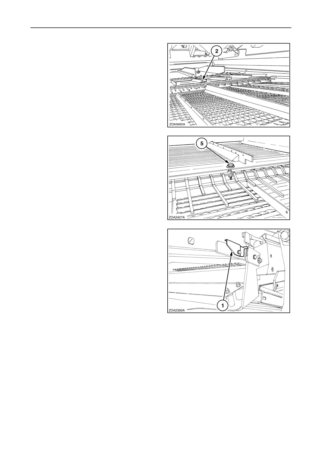
SECTION 3 - FIELD AND SITE OPERATION
3. Move slowly lever 2 (open/close) on the presieve
until the presieve falls completely into his place.
117
4. If ok, insert and tighten two bolts 5 on both sides
of the presieve.
118
5. Check by moving the lever 1 at the back of the
shaker shoe.
NOTE: Moving lever 1 will cause the presieve to open
or close.
119
3-68
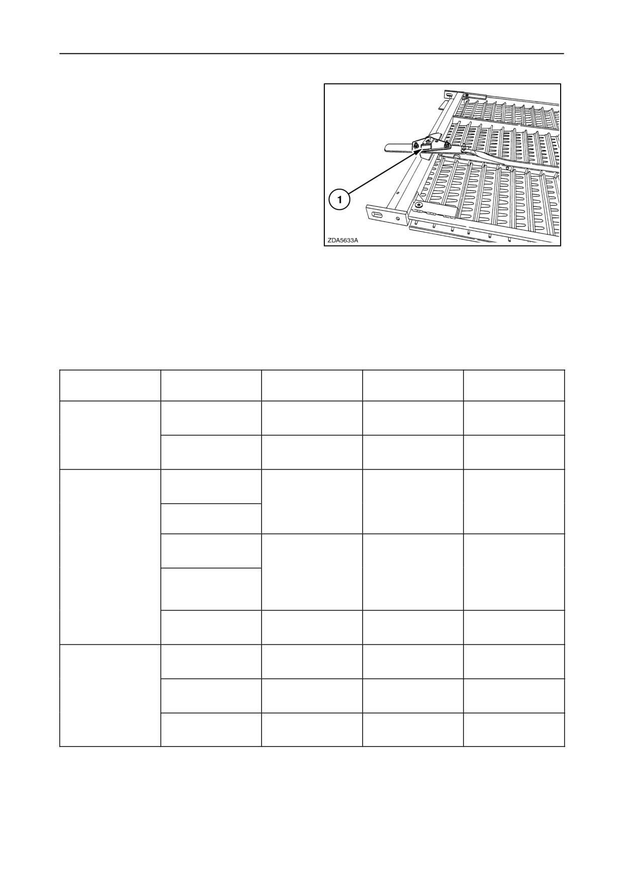
SECTION 3 - FIELD AND SITE OPERATION
• Lower and Upper sieve
NOTE: On the CX800 models, the lower and upper
sieve consists of two sieve halves, and if the sieves
are equipped with remote control it is not possible to
exchange the left-hand with the right-hand side sieve
halve, because the left-hand side sieve is foreseen
with a welded support 1.
120
To install the sieves, proceed in reverse order. To
adjust the left and right-hand sieve halves (upper and
lower sieve) and to obtain the same opening, refer to
SECTION
4
-
“LUBRICATION
AND
MAINTENANCE”, paragraph: “Cleaning”.
Types of sieves available
Sieves
Type
Crops
Positions
Opening
Hart Carter
Maize
Fixed
Adjustable
1-5/8”
Presieve
New Holland
Cereals
Fixed
Adjustable
1-1/8”
Maize
Hart Carter
1-1/8”
Cereals
Two
Adjustable3
Closz sieve
Hart Carter
1-5/8”
Upper sieve
Maize
Two2
Adjustable3
Stainless steel
curved louver
maize sieve
Petersen sieve
Oil seed rape
Two
Adjustable3
1-1/8”
New Holland
Cereals
Fixed
Adjustable3
1-1/8”
Maize
Round hole sieve
Lower sieve
Maize
Fixed
Fixed
16 mm diameter
Round hole sieve
Maize
Fixed
Fixed
18 mm diameter
(2) sieve with canvas installed in the upper position.
(3) mechanical or electrical (remote control) sieve adjustable.
3-69
SECTION 3 - FIELD AND SITE OPERATION
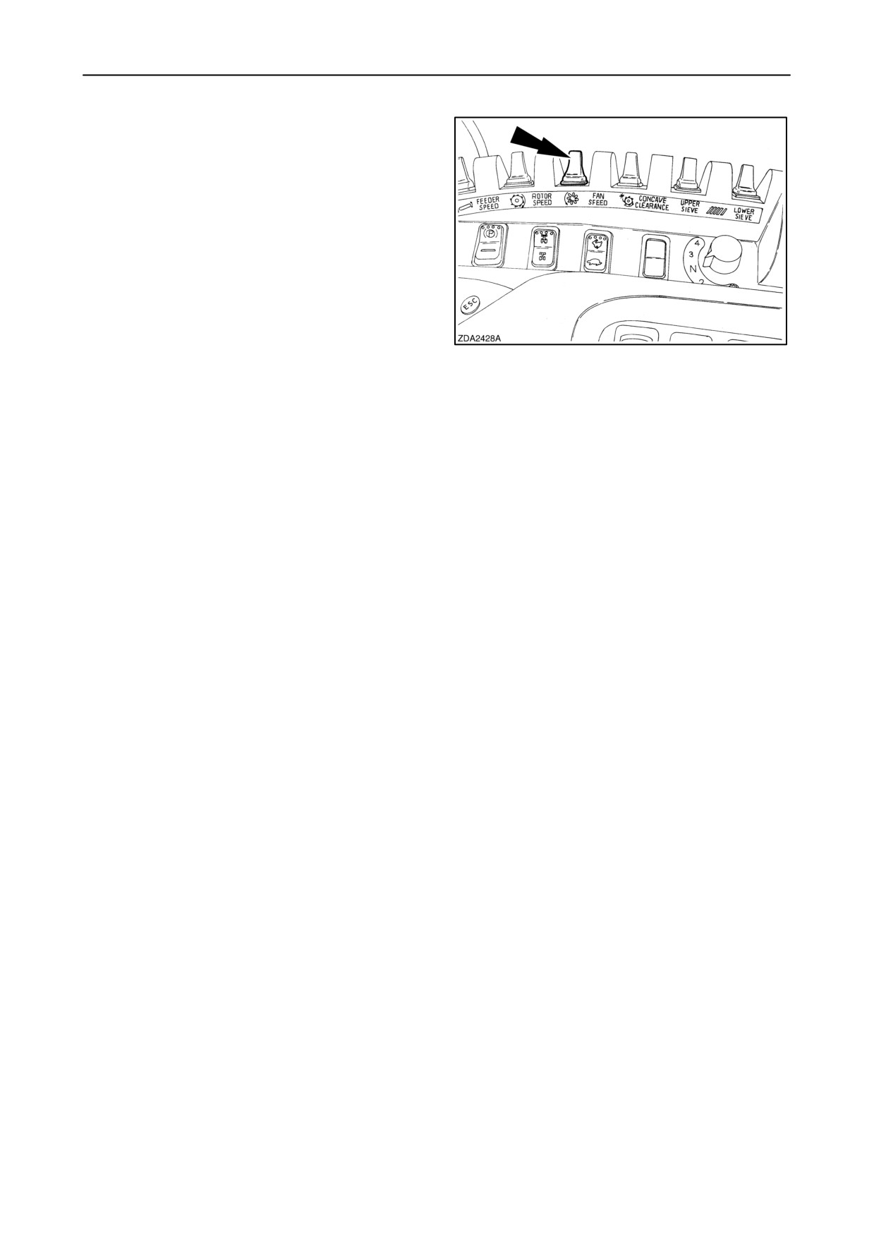
Cleaning fan
The cleaning fan speed can be adjusted electrically
from the operator’s platform and can be read from the
InfoViewt monitor.
It’s only possible to change the fan rpm when the
threshing mechanism is engaged.
121
Adjust it to suit the nature of the crop, chaff load and
moisture content. A grass seed variator kit can be
installed to obtain a lower fan speed regulation when
threshing small seeds. An insufficient air blast will
reduce the”clean area” of the top sieve causing a dirty
sample or grain loss (grain will shake over the end of
the shaker shoe).
The best way to check whether the volume of air is
satisfactory is to complete a ”kill-stall”, i.e. stopping
the engine with the threshing mechanism engaged
and checking the sieve coverage pattern.
If this method of checking is used:
• The two rakes must be clean while the sieves
must be evenly loaded. Little or no grain should
be found on the rear part of the upper sieve.
• If the whole sieve is clear of grain and chaff, the
volume of air is too high. The grain will be blown
out of the machine and clean grain will be
transported over the lower sieve into the returns
cross auger.
• If the upper sieve is full of grain, the volume of air
is too low, so that the wind does not blow through
the chaff. Therefore grain will be shaken off the
sieve together with the chaff.
Sieve operation can also be checked by collecting
material coming from the rear of the cleaning shoe
and checking the sample for grain loss.
3-70
SECTION 3 - FIELD AND SITE OPERATION
IMPORTANT: Do not remove or modify the cleaning
fan guards as changes may influence the airflow in an
unfavourable way.
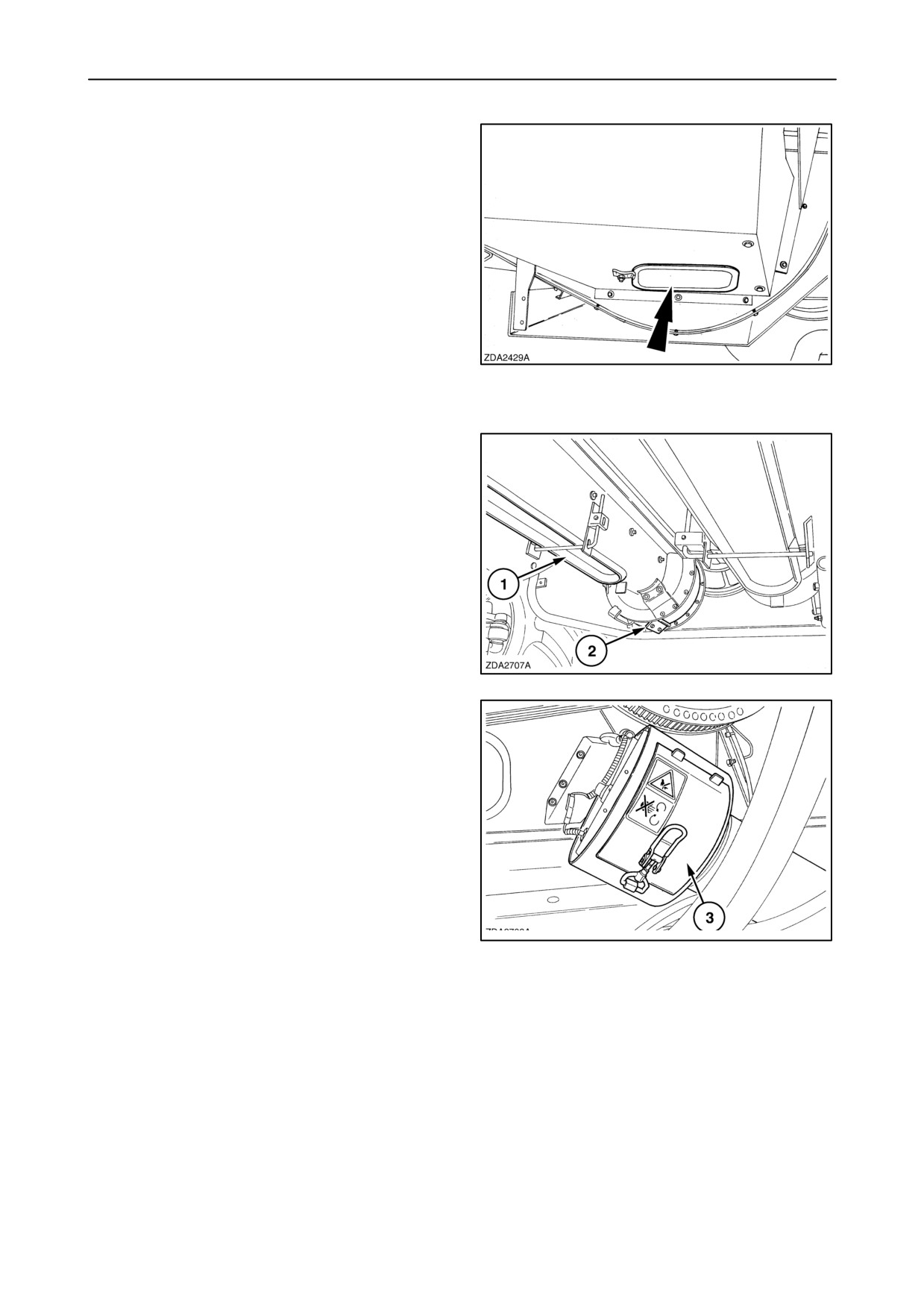
In some conditions it is necessary to clean
sometimes the inside of the fan shielding.
To clean open the covers on both sides of the
shielding.
122
Returns system
• CX700 models: Single returns auger.
• CX800 models: Double returns auger.
The returns cross auger can be cleaned by removing
cover 1.
Should the roto-threshers become blocked, they can
be unblocked and cleaned through opening 2.
123
A blocked thrower can be unblocked through cover 3.
For maximum efficiency it is important to keep the
amount of material in the returns auger to the
absolute minimum.
EXCESSIVE RETURNS WILL:
- Increase the risk of grain damage.
- Produce grain loss through sieve overload.
- Increase the risk of blocking the returns
components.
124
3-71
SECTION 3 - FIELD AND SITE OPERATION
THE QUANTITY OF RETURNS CAN BE LIMITED
BY:
- Opening the lower sieve as wide as possible,
consistent with producing a clean grain sample.
- Not opening the presieve and the upper sieve too
wide (this will stop excessive chaff from getting
onto the bottom sieve)
- Keeping the cleaning fan rpm high enough to
blow the chaff out of the machine.
- Avoiding excessive cleaning fan rpm, so that
clean grain is not blown over the lower sieve into
the returns cross auger.
To adjust the rotor-thresher drum, refer to section 4
”Lubrication and maintenance”.
When harvesting maize, rape seed and other crops
with large fragile grains
(e.g. beans), smooth
roto-thresher cover(s) 2 (delivered with the combine)
should be installed to prevent grain damage.
125
3-72
SECTION 3 - FIELD AND SITE OPERATION
GRAIN STORAGE/UNLOADING
Grain tank filling system
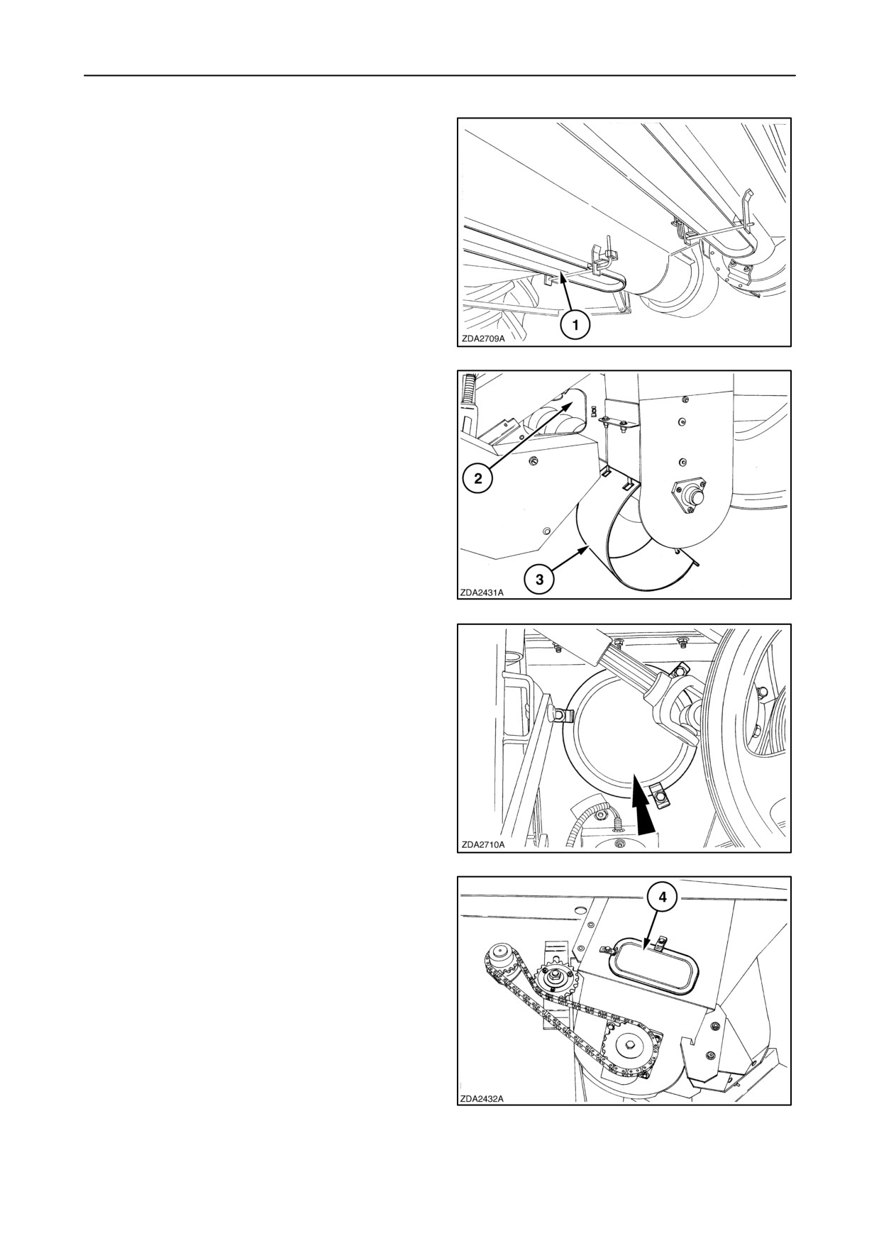
• The grain cross auger can be cleaned by
removing cover 1.
126
• The grain elevator bottom side can be cleaned by
removing covers 2 and 3.
127
• Open the cover to check the grain cross auger.
128
• The grain elevator top side can be cleaned by
removing cover 4.
129
3-73
SECTION 3 - FIELD AND SITE OPERATION
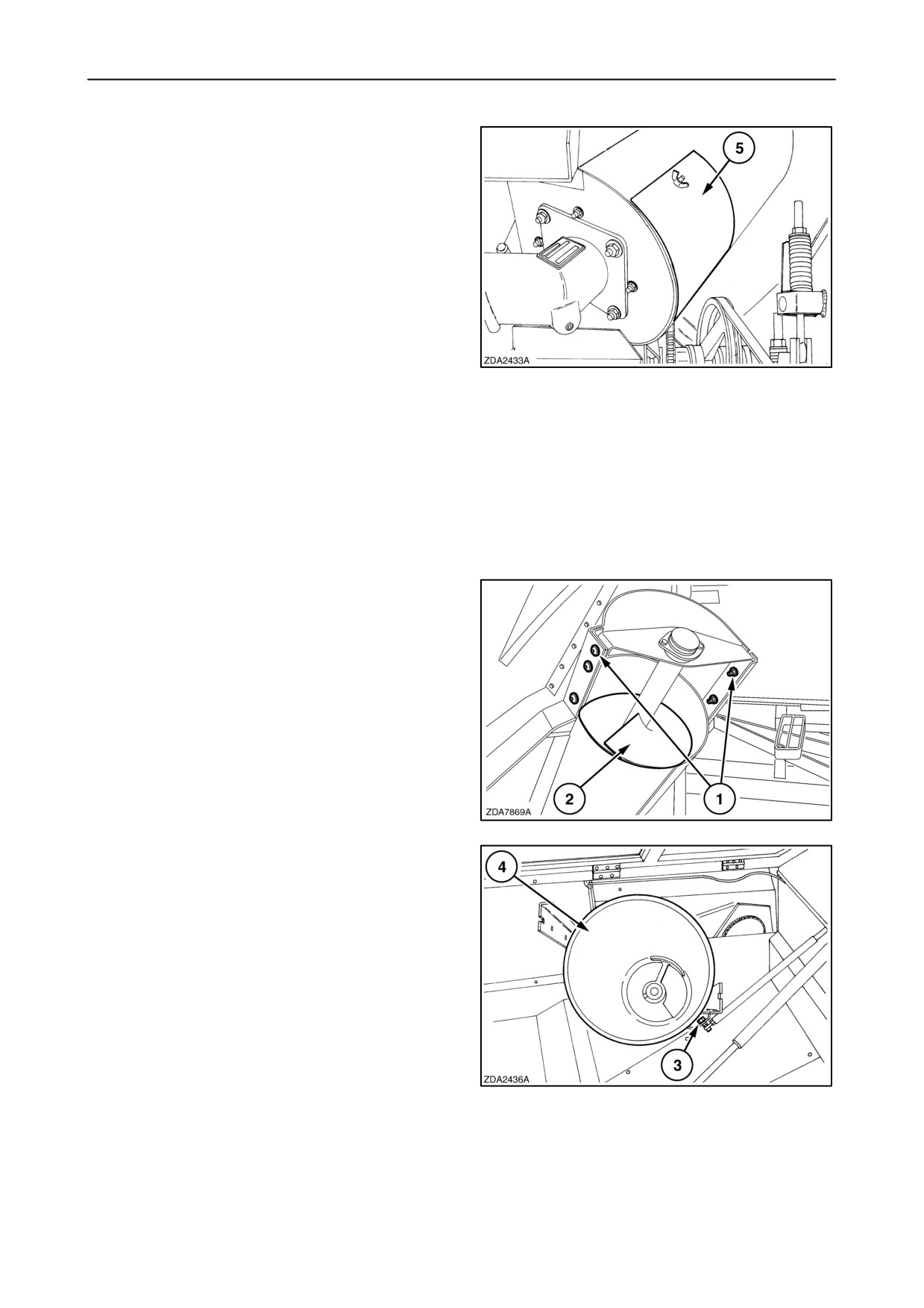
• In damp crop conditions (e.g. wet maize,wet soya
beans),it may be necessary to regularly clean the
passage between the grain elevator and the grain
tank bubble-up auger. Access to this area can be
obtained by removing covers 4 and 5.
130
• The grain tank bubble-up augers can be easily
removed to clean it thoroughly.
Proceed as follows:
Removal
1. Open the grain tank extensions or covers.
2. Remove the roof.
3. Loosen two bolts
1 and remove the upper
bubble-up auger 2.
131
4. Remove bolt 3 (if grain tank covers installed) and
swing open bubble-up tube 4.
132
3-74
SECTION 3 - FIELD AND SITE OPERATION
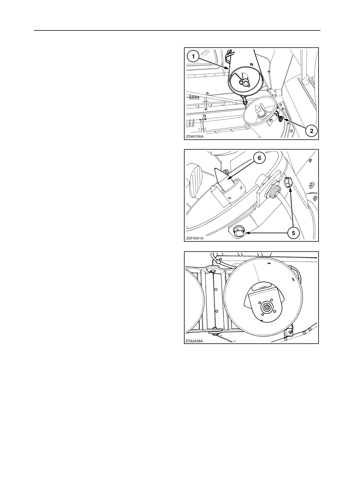
NOTE: Open fast coupler 2 (if extensions) to swing
open bubble-up tube 1.
133
5. Loosen two bolts
5 and remove the sensor
support with the sensor.
6. Remove the anchor bearing housing and the
lower bubble-up auger 6.
134
When harvesting wet soya beans it is recommended
to perform this job every day.
135
3-75
SECTION 3 - FIELD AND SITE OPERATION
Installation
1. Guide the auger into the lower bubble-up tube
and make sure the auger bottom fits over the
gearbox output shaft.
2. Install the bolts of the bearing support and wait to
tighten the bolt with the sensor plate.
3. Install the draw bar and tighten the bolt at
3.(fig. 132) (if grain tank covers)
IMPORTANT: Check if the balljoints of the draw bar
are positioned in line.
NOTE: Close the fast coupler (with extensions).
4. Tighten the bolt with the sensor plate and adjust
the sensor.
5. Install the upper bubble-up auger and tighten the
bolts.
6. Attach the rope to keep the upper grain tank
covers close. (if installed)
3-76
SECTION 3 - FIELD AND SITE OPERATION
Grain sample access
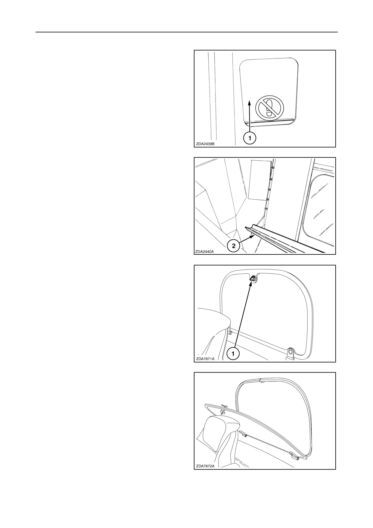
The grain tank is provided with an inspection door 1
where a grain sample can be taken when starting off
in the field.
136
A channel section 2 in the grain tank brings the grain
to the inspection door.
137
Grain tank window
Open the grain tank window in the cab by turning the
knob (1) to clean the area between the cab and the
grain tank.
138
139
3-77
SECTION 3 - FIELD AND SITE OPERATION
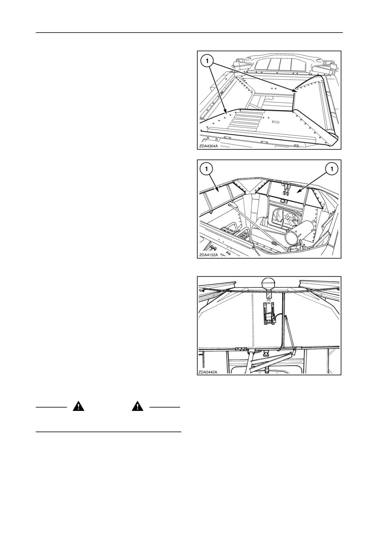
Grain tank with extensions
Closed position of grain tank extensions 1.
140
The grain tank extensions 1 can be opened manually.
141
Grain tank with covers
The grain tank with covers can be opened electrically
(with actuator) from the cab if the field mode is
selected and if the threshing mechanism is not
engaged.
At the same time, the bubble-up tube opens.
To prevent damage to the bubble-up tube is it not
possible to engage the threshing mechanism as long
as the covers are moving.
142
NOTE: Do not close or open the grain tank
extensions with a full grain tank.
WARNING
Be careful: excessive height with open grain tank
covers: 4.8 m (15.75 ft)
3-78
SECTION 3 - FIELD AND SITE OPERATION
NOTE: The only actions to stop moving the grain tank
covers are:
• Depress the emergency stop button.
• Turn the ignition key off.
• If the covers motor (actuator) needs more than 18
Ampere to work.
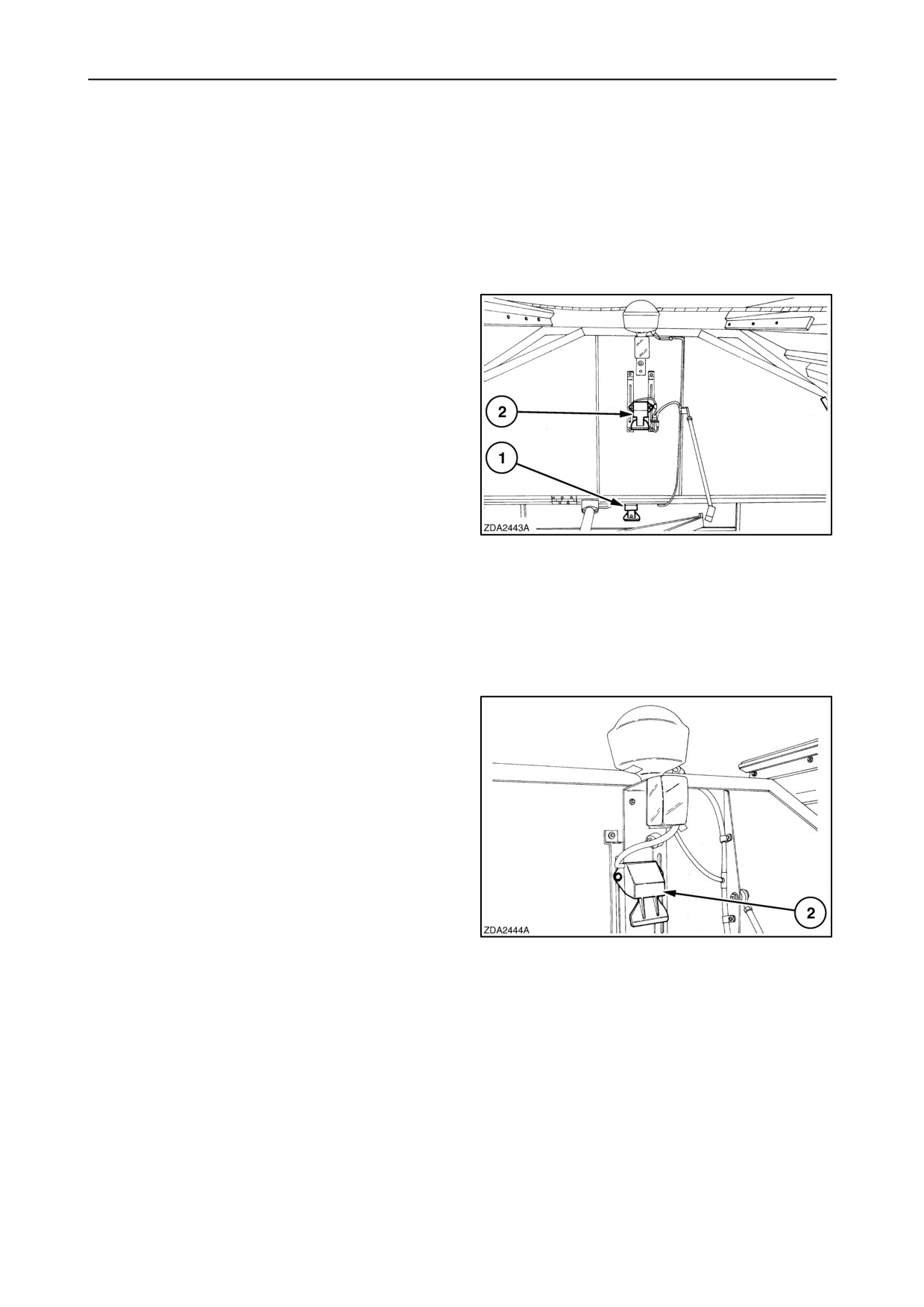
Grain tank level sensor
There are two grain tank level sensors shown.
- Lower level sensor 1: (Fixed sensor)
When the grain reaches this level sensor, the
following can be observed:
• The grain tank level warning light will illuminate
(SSM).
• The revolving flash light(s) will be switched on:
(If threshing engaged)
143
• Continuously, if the operating lights are
switched off.
• For 10 seconds, if the operating lights are
switched on.
- Upper level sensor 2:
Adjust this sensor, according to the condition of the
crop.
When the grain reaches level sensor 2:
• The grain tank level warning light will blink (SSM).
(Warning light will not blink if not driving or if straw
elevator is not engaged)
• A message of full grain tank appears on the
InfoViewt monitor.
144
• An audible alarm sounds
(only if thresher
engaged).
• The revolving flash light(s) will be switched on:
(If threshing engaged)
• For 10 seconds, if the operating lights are
switched on.
3-79