New Holland CX720, CX740, CX760, CX780, CX820, CX840, CX860, CX880. Operator's Manual - page 6
SECTION 2 - CONTROLS, INSTRUMENTS AND OPERATION
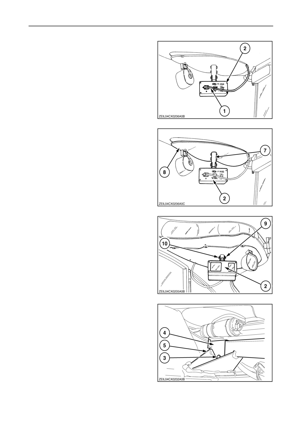
8. To adjust, disconnect the wiring loom 1 from the
HGS sensor 2.
229
9. Remove the HGS sensor assembly 2 from the
spindle 7.
10. Remove the Allen screws to remove the cover 8
on the cab roof.
230
11. Re-install the HGS sensor assembly 2 and fix in
place with the bolts 9, lock washers and nuts 10.
231
12. Loosen the bolt connection 3 and move the
bracket 4 with the turntable actuator on the cross
member 5 to the right or to the left until the HGS
sensor 2 (fig. 229) looks straight forward.
NOTE: This is not the operating position of the
SmartSteert
13. Tighten the bracket
4 in place with the bolt
connection 3.
14. The turntable calibration is now done.
232
2-130
SECTION 2 - CONTROLS, INSTRUMENTS AND OPERATION
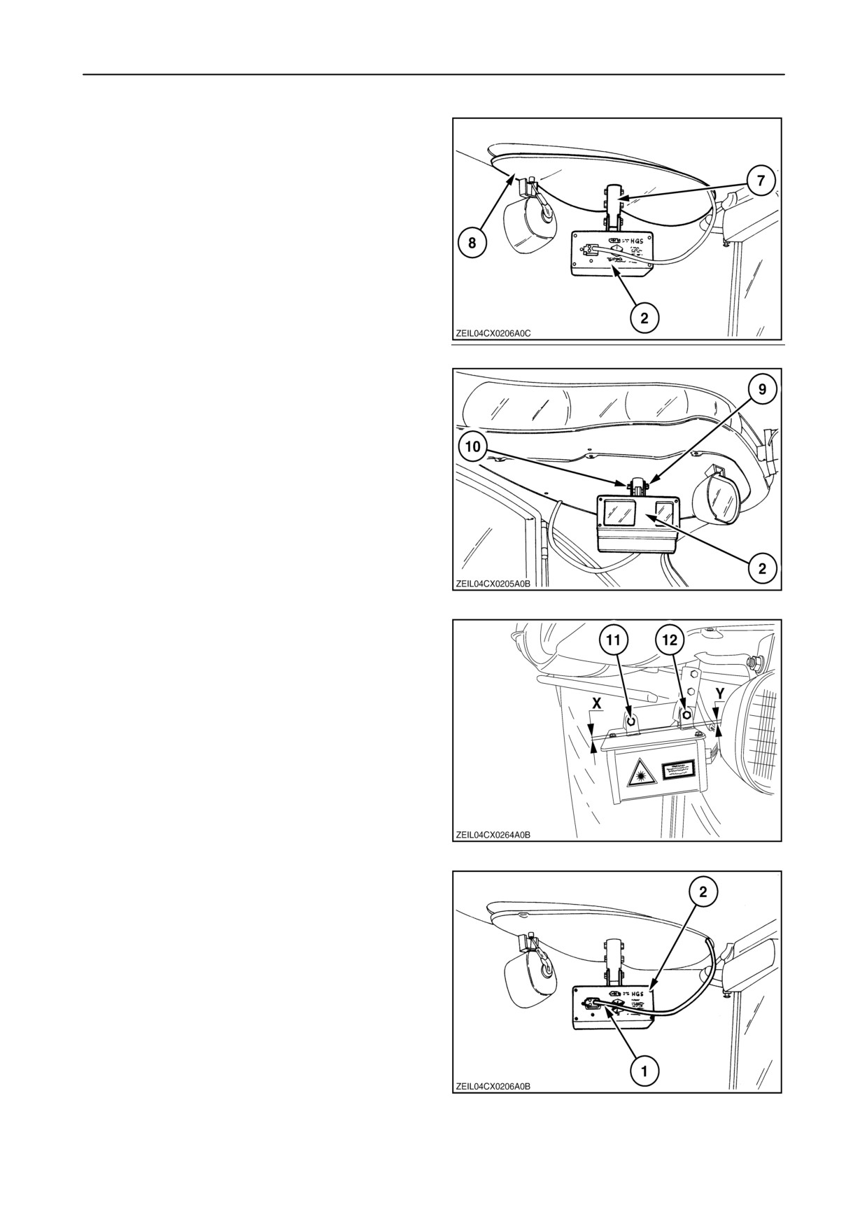
15. Remove the HGS sensor assembly 2 from the
spindle 7 and install the cover 8 on the cab roof
and tighten the Allen screws.
233
16. Re-install the HGS sensor assembly 2 and fix in
place with the bolts 9, lock washers and nuts 10.
234
17. Make sure that distance “X” = “Y”.
Adjust with the bolts (11) and (12).
235
18. Connect the wiring loom 1 to the HGS sensor 2.
NOTE: Leave the wiring loom 1 sufficiently long so
the HGS sensor 2 can be turn freely to the left and to
the right.
236
2-131

SECTION 2 - CONTROLS, INSTRUMENTS AND OPERATION
Error
Possible cause
Remedy
1
SmartSteert state is enabled or active
Disable SmartSteert by pressing shortly on
the enable switch on the RHM
4
After 10 seconds, the end-of-travel of the
Check wiring to the actuator motor; make
actuator was still not detected; end-of-travel is
sure battery voltage of the combine is OK;
detected when current is above 6 A for
retry with engine running if battery voltage is
100 ms (0.1 s)
low
5
User has pressed ESC (or Quick stop) button
Do not press the ESC (or Quick stop) button
during the calibration
during the calbration
32
Autopilot type is different from “1”
Set Autopilot type to “1” (= SmartSteert)
(= SmartSteert)
66
Result of the calibration is invalid due to:
- supply voltage of sensor to low
Check voltage supply to the actuator
potentiometer (should be +/- 5 V)
- sensor signal not changing enough
Make sure the actuator can move freely; if
(range < 2.2 V between fully
OK, the actuator or the sensor inside might
extended/retracted position)
be faulty. In this case, replace the actuator.
67
Feedback signal from actuator potentiometer
is outside the expected limits
(< 0.1 V or > 5.0 V)
Voltage supply problem
Check voltage supply to the actuator
potentiometer (should be +/- 5 V)
Sensor problem
Check sensor in actuator
Connector problem
Check all connectors between the actuator
and the CCM3 (Refer to your local Dealer)
Wiring problem
Check all wiring between the actuator and the
CCM3 (Refer to your local Dealer)
68
Feedback signal from actuator position is not
valid:
- Sensor problem
Check feedback sensor in actuator and
eventually replace actuator
- Connector problem
Check all connectors between the actuator
and the CCM3 (Refer to your local Dealer)
- Wiring problem
Check all wiring between the actuator and the
CCM3 (Refer to your local Dealer)
2-132
SECTION 2 - CONTROLS, INSTRUMENTS AND OPERATION
Straight steer calibration
This calibration will calibrate the sensor in the rear
axle steering cylinder to its “0”
(driving straight forward) position.
This calibration has to be done:
• only once after the installation of the right steering
cylinder.
• on level ground and in an area where you can
drive the combine straight forward:
To calibrate, proceed as follows:
IMPORTANT: Make sure you have done the
“Calibration of the HGS turntable actuator” before
continuing.
1.
Start the engine and turn the steering wheel so
that the sensor in the steering column recognises
the movement.
Turn the steering wheels into a position for driving
straight forward. Test by driving the combine for
a short distance and verify that the combine
follows a straight line.
2.
Enable the SmartSteert system by pressing the
SmartSteert rocker switch for minimum two
237
seconds.
3.
The SmartSteert icon will appear greyed in the
upper left-hand corner of the InfoViewt monitor.
4.
Press and hold the SmartSteert rocker switch
for at least 5 seconds, until the SmartSteert icon
starts blinking, indicating that the calibration
mode has been entered. Keep the button pressed
for another three seconds to calibrate the
steering cylinder sensor. The icon on the
InfoViewt will become solid greyed out again.
5.
The calibration is done.
238
6.
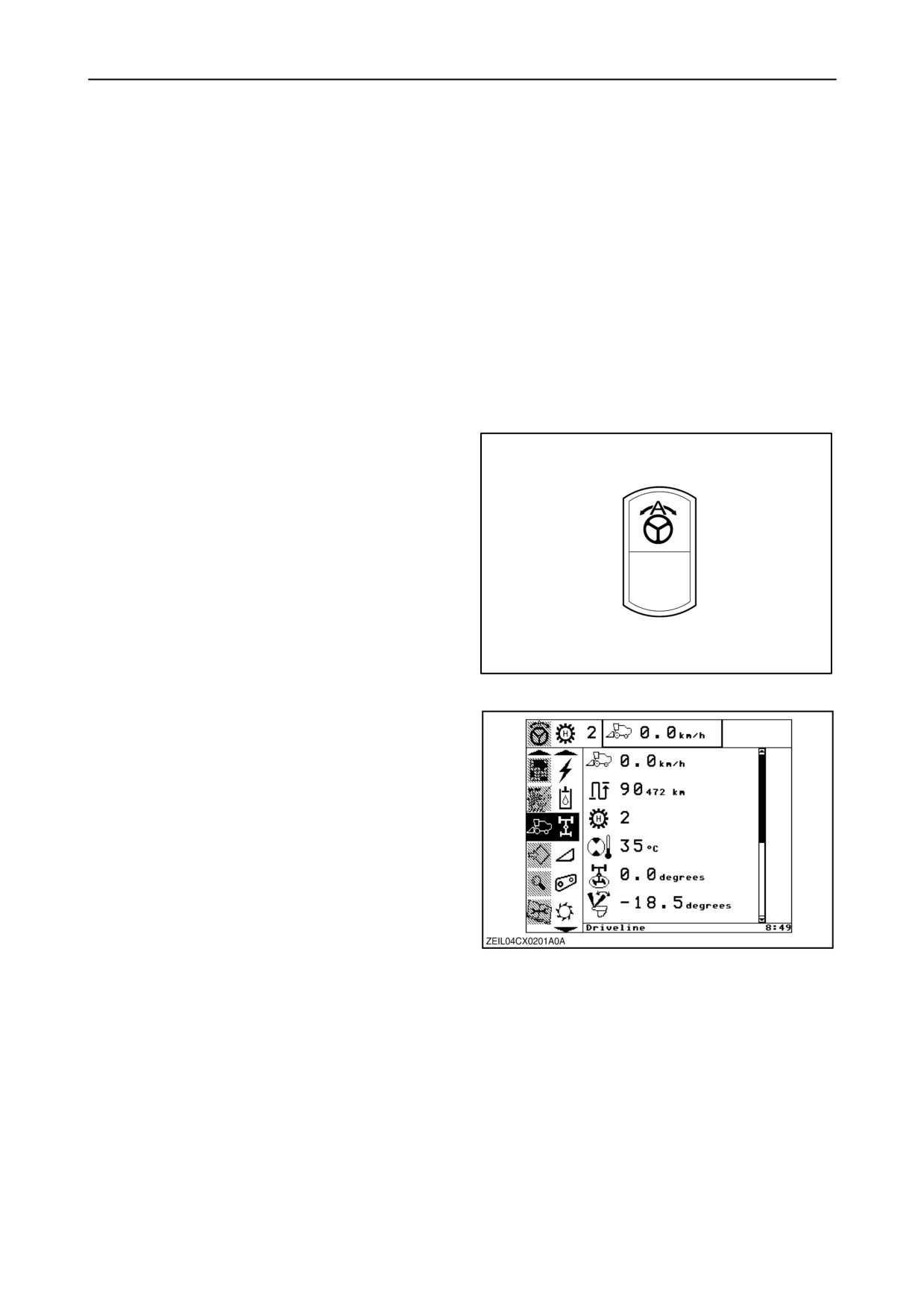
After a successful calibration and with the
steering wheels in a straight forward driving
position, the calibration value shown in the
“driveline screen” should be 0.0 degrees.
(turning to the left show negative (-) values,
turning to the right show positive (+) values)
2-133
SECTION 2 - CONTROLS, INSTRUMENTS AND OPERATION
Crop edge calibration
The “Crop edge calibration” has to be done in the field
in real harvesting conditions.
IMPORTANT: Make sure you have done the
“Calibration of the HGS turntable actuator” before
continuing.
The
“Crop edge calibration” will adjust the
SmartSteert sensor to detect a left-hand or a
right-hand crop edge automatically when the
combine is placed straight forward along a straight
crop edge.
The “Crop edge calibration” has to be carried out:
• with the header you intend to use attached to the
combine.
• every time a header with a different width is
attached to the combine.
• every time a new crop is harvested or if the
crop-characteristics
change considerably
(height, density, standing or laid down)
NOTE: There is no separate left-hand or right-hand
side “Crop edge calibration”.
Make sure the combine is positioned parallel along a
straight crop edge in a part of the field with a
representative crop for the whole field. To check this,
drive some distance forward without turning the
steering wheel.
As the SmartSteert sensor scans the field at a
distance of 10 to 20 meters, make sure no obstacles
are close to the crop edge in this area.
We recommended you to cut at least one full header
width for at least 20 meters in front of the position of
the combine to create a clean and free standing crop
edge for the calibration.
2-134
SECTION 2 - CONTROLS, INSTRUMENTS AND OPERATION
Calibration of the HGS Turntable sensor
1. Turn the steering wheel slightly so that the sensor
in the steering column recognises the steering
wheel.
2. Activate the SmartSteert system by pressing
and holding the SmartSteert rocker switch for a
minimum of two seconds.
3. The SmartSteert icon will appear greyed out in
the upper left corner of the InfoViewt monitor.
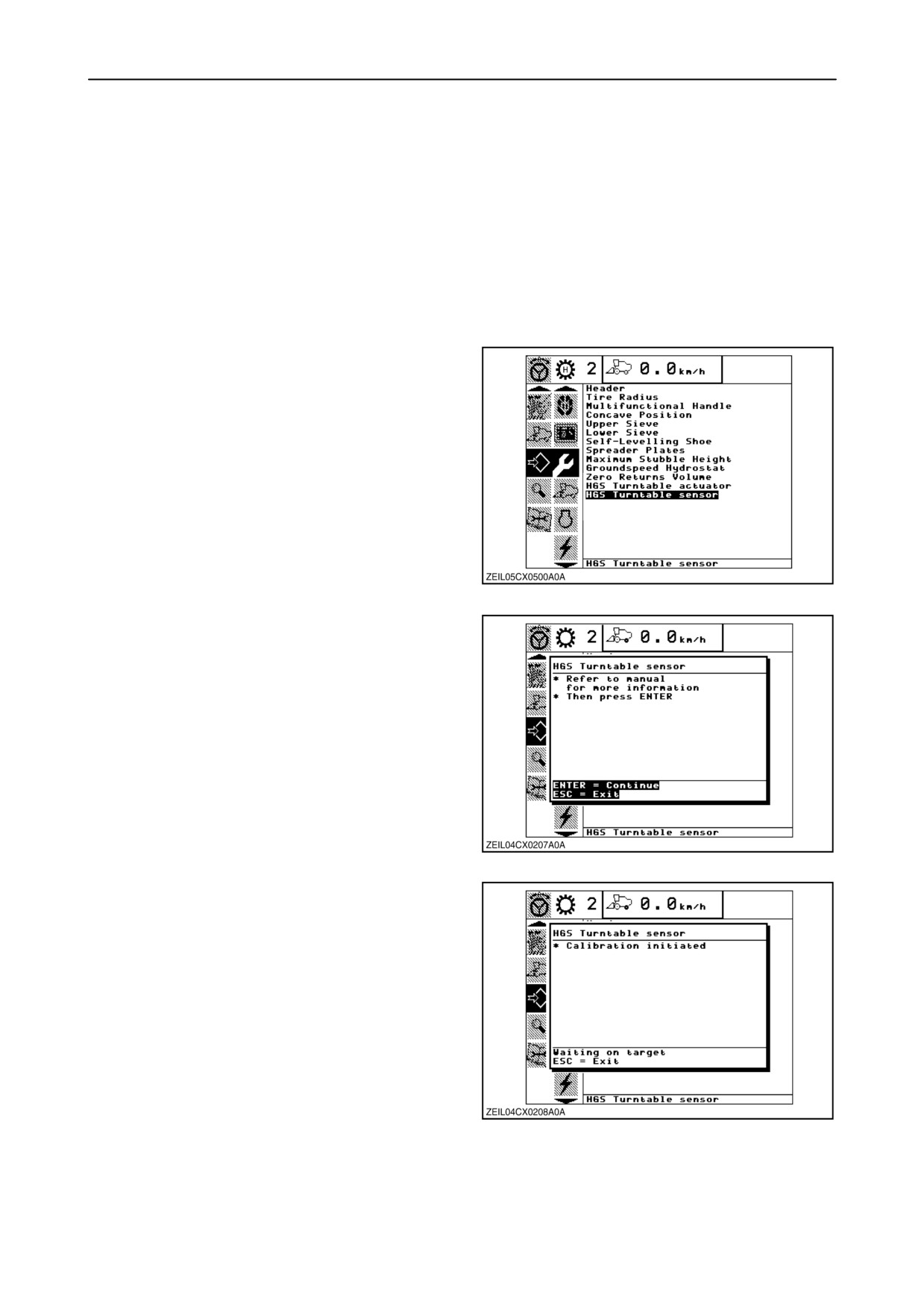
4. Select the calibration sub-menu and press the
“right” navigation key to enter the information box.
5. Select item “HGS Turntable sensor”, using the
navigation key and press “enter”.
239
Message: “Refer to manual for more information”
Message: “Then press ENTER”
6. Press “enter” to continue or “esc” to abort the
calibration.
240
Message: “Calibration initiated”
7. The SmartSteert sensor will now search and
determine the position of the crop edge, left-hand
side or right-hand side of the header.
241
2-135
SECTION 2 - CONTROLS, INSTRUMENTS AND OPERATION
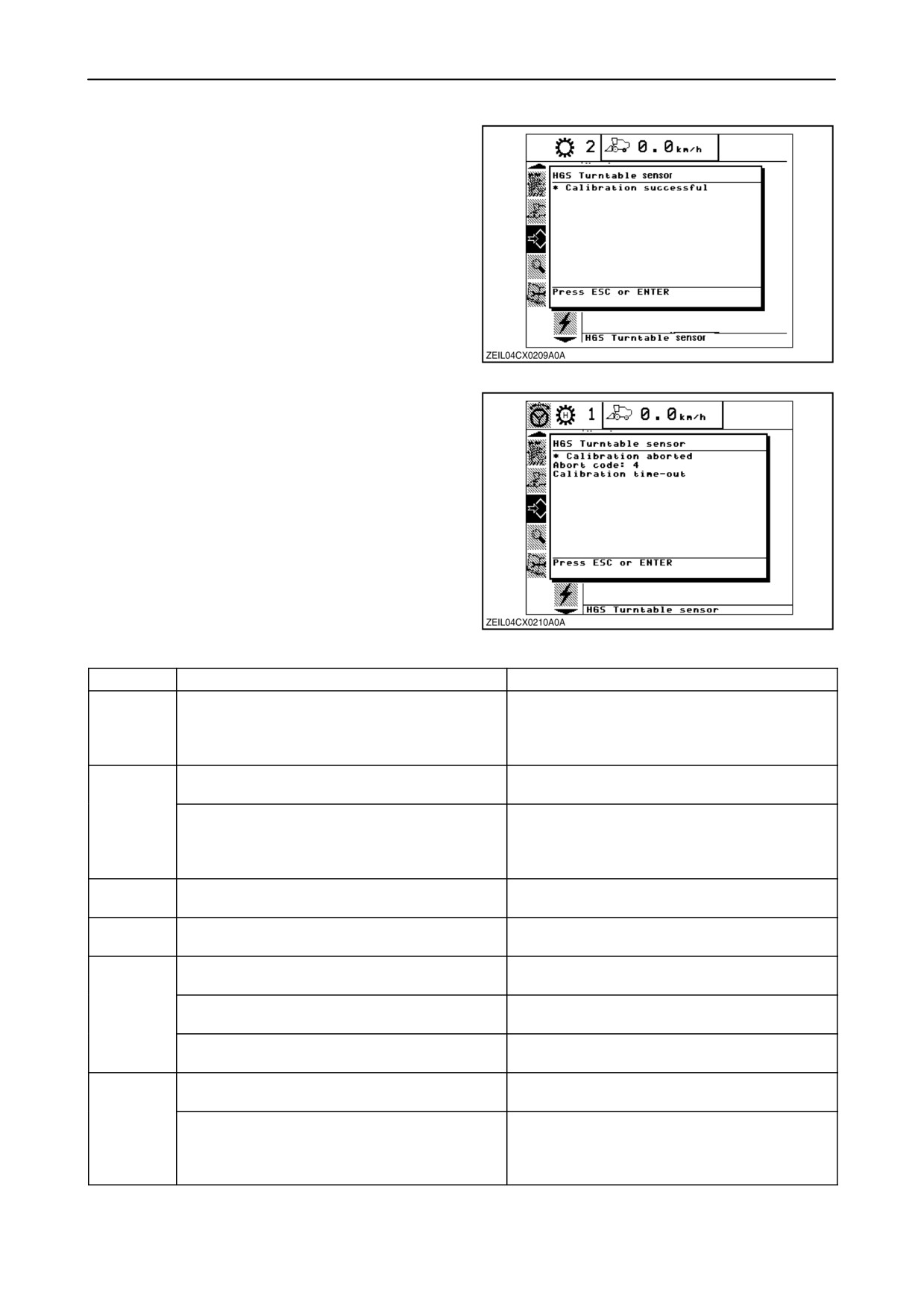
Message: “Calibration successful”
8. When the InfoViewt monitor indicates that the
calibration has finished successfully, verify that
the HGS sensor is looking to the intended crop
edge by driving with a minimum speed of 0.5
km/h.
242
NOTE: If the HGS sensor does not find the crop edge
within a certain time limit then this message will be
viewed on the InfoViewt monitor as shown.
9. Drive the combine to a new position and
recalibrate as instructed above.
243
Error
Possible cause
Remedy
1
SmartSteert is not enabled
Enable SmartSteert by pressing long on the
Enable switch on the RHM (if icon is not
shown), or stop driving (if SmartSteert is in
automatic = active mode)
4
No crop edge found
Put the combine (with header) in front
(straight line) of a crop edge
Actuator did not reach the desired position or
Check HGS sensor (does it move? is the
CCM3 did not receive a proper answer over
glass not covered with dust? are the lenses
CAN from the HGS sensor
moving?). Check that you are in front of a
proper crop edge and retry a calbration
5
User has pressed ESC (or Quick stop) button
Do not press the ESC (or Quick stop) button
during the calibration
during the calbration
32
Autopilot type is different from 1
Set Autopilot type to 1 (= SmartSteert)
(= SmartSteert)
68
Feedback signal from actuator position is not
Check feedback sensor in actuator and
valid: sensor problem
eventually replace actuator
connector problem
Check all connectors between the actuator
and the CCM3 (Refer to your local Dealer)
wiring problem
Check all wiring between the actuator and the
CCM3 (Refer to your local Dealer)
69
HGS sensor is not sending messages on the
CAN line(s) to HGS disconnected and/or
CAN bus
sensor malfunction
HGS sensor is not powered
Check power lines to the HGS sensor (could
be connector, wiring, or voltage supply issue
e.g. blown fuse F-49, relay K-26 not working
correctly, missing ground X124
2-136
SECTION 2 - CONTROLS, INSTRUMENTS AND OPERATION
6. Combine
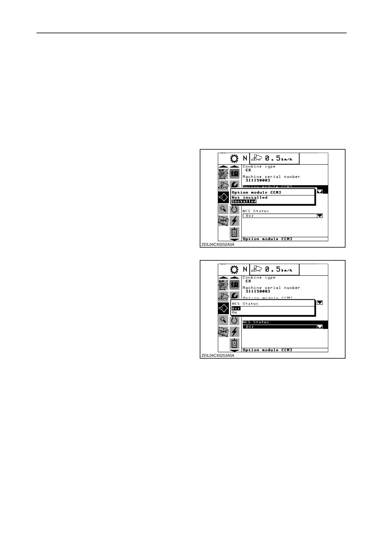
In this sub-menu the operator can set the following
items.
• Option module CCM 3
• ACS status
NOTE: The other items mentioned are factory-set
and does not need to be changed.
• Option module CCM 3
If press “enter” when this item is selected, a pop-up
screen appears, showing the two possibilities
“Installed” or “Not installed”.
Using the ”up” or “down” navigation keys to select and
press “enter” to confirm your choice.
244
• ACS status
If press “enter” when this item is selected, a pop-up
screen appears, showing the two possibilities “Off” or
“On”.
Using the ”up” or “down” navigation keys to select and
press “enter” to confirm your choice.
245
2-137
SECTION 2 - CONTROLS, INSTRUMENTS AND OPERATION
7. Engine
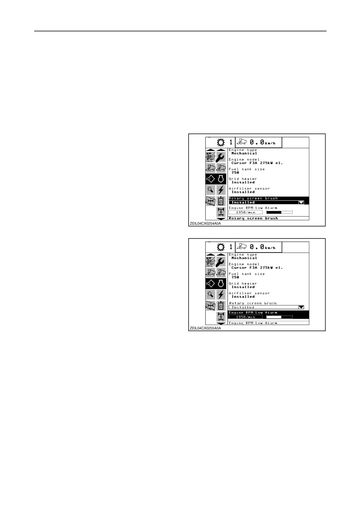
In this sub-menu the operator can set following items:
• Rotary screen brush
• Engine RPM low alarm
NOTE: The other items mentioned are factory-set
and does not need to be changed.
• Rotary screen brush
If press “enter” when this item is selected, a pop-up
screen appears, showing the two possibilities
“Installed” or “Not installed”.
Using the ”up” or “down” navigation keys to select and
press “enter” to confirm your choice.
246
• Engine RPM low alarm
To change the value, using the “+” and “-” navigation
keys and press enter to store.
Factory set=1950 rpm
247
2-138
SECTION 2 - CONTROLS, INSTRUMENTS AND OPERATION
8. Electrical
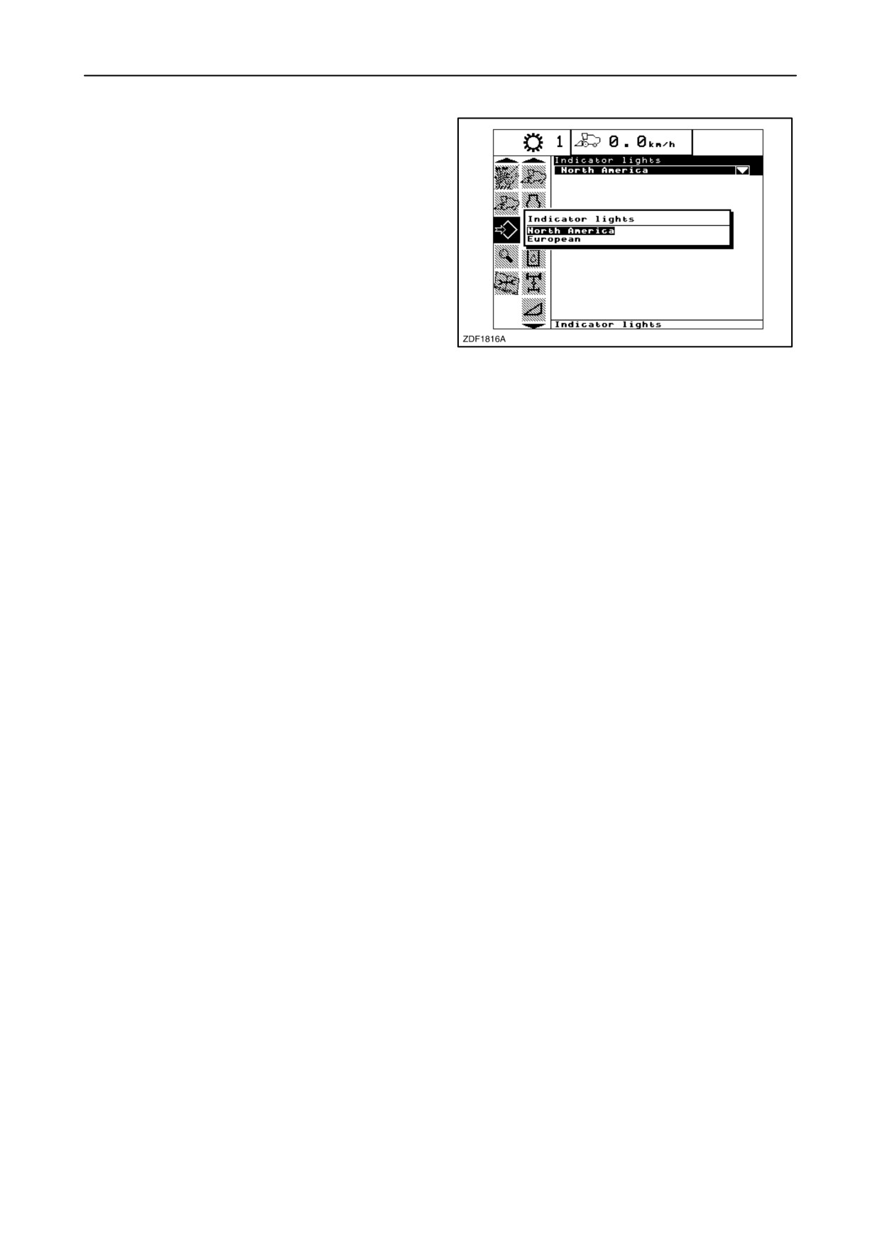
In this sub-menu the operator can set the following
item:
• Indicator lights
If press “enter” when this item is selected, a pop-up
screen appears, showing the two possibilities
“European” or “North America”.
Using the ”up” or “down” navigation keys to select and
press “enter” to confirm your choice.
248
9. Hydraulics
In this sub-menu, all settings are factory set and do
not need to be changed.
2-139
SECTION 2 - CONTROLS, INSTRUMENTS AND OPERATION
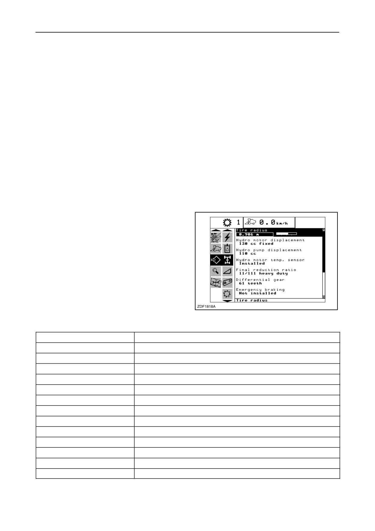
10. Driveline
In this sub-menu the operator can set following items:
• Tyre radius
• Rear wheel assist
• Dual range (Only if rear wheel assist is installed)
• Tracks type
• Autopilot type
NOTE: The other items in this sub-menu are factory
set and should not be changed.
• Tyre radius
To change, proceed as follows:
1. Select item “Tyre radius”.
2. To change the value of the tyre radius, using the
“+” and “-” navigation keys and press enter to
store.
NOTE: The number of the tyre radius can be find in
the listed below.
249
Tyre radius
Traction Tyre
Tyre radius value
620/75R34-170A8-DT820
0.859 m
650/75R32-172A8-DT822
0.863 m
710/70R34-178A8-MegaXBib
0.897 m
800/65R32-172A8-DT822
0.864 m
800/65R32-172A8-XM28
0.869 m
900/60R32-176A8-DT830
0.919 m
900/60R32-176A8-MegaXbib
0.893 m
900/65R32-172A8-TD8
0.956 m
1050/50R32-178A8 MegaXBib
0.899 m
18.4R42-153A8-RAT23 (duals)
0.881 m
20.8R42-155A8-RAT23 (duals)
0.922 m
420/80R46-159A8-RAT23 (duals)
0.889 m
Tracks
0.352 m
2-140
SECTION 2 - CONTROLS, INSTRUMENTS AND OPERATION
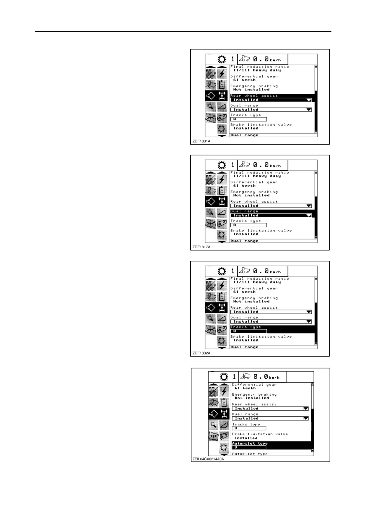
• Rear wheel assist
If press “enter” when this item is selected, a pop-up
screen appears, showing the two possibilities
“Installed” or “Not installed”.
Using the ”up” or “down” navigation keys to select and
press “enter” to confirm your choice.
250
• Dual range
NOTE: Only on the screen if a power rear axle is
installed.
If press “enter” when this item is selected, a pop-up
screen appears, showing the two possibilities
“Installed” or “Not installed”.
Using the ”up” or “down” navigation keys to select and
press “enter” to confirm your choice.
251
• Tracks type
The operator can make a choice between number “0”,
”1” and “2”.
If select “0”: tyres are selected.
Select “1” or “2” when using tracks.
To change the number of the tracks type, using the “+”
and “-” navigation keys and press enter to store.
252
• Autopilot type
The operator can make a choice between number “0”,
”1” and “2”.
“0” = Not installed
“1” = SmartSteert
“2-7” = Future options
To change the number of the tracks type, using the “+”
and “-” navigation keys and press enter to store.
NOTE: In this case select ”1”.
253
2-141
SECTION 2 - CONTROLS, INSTRUMENTS AND OPERATION
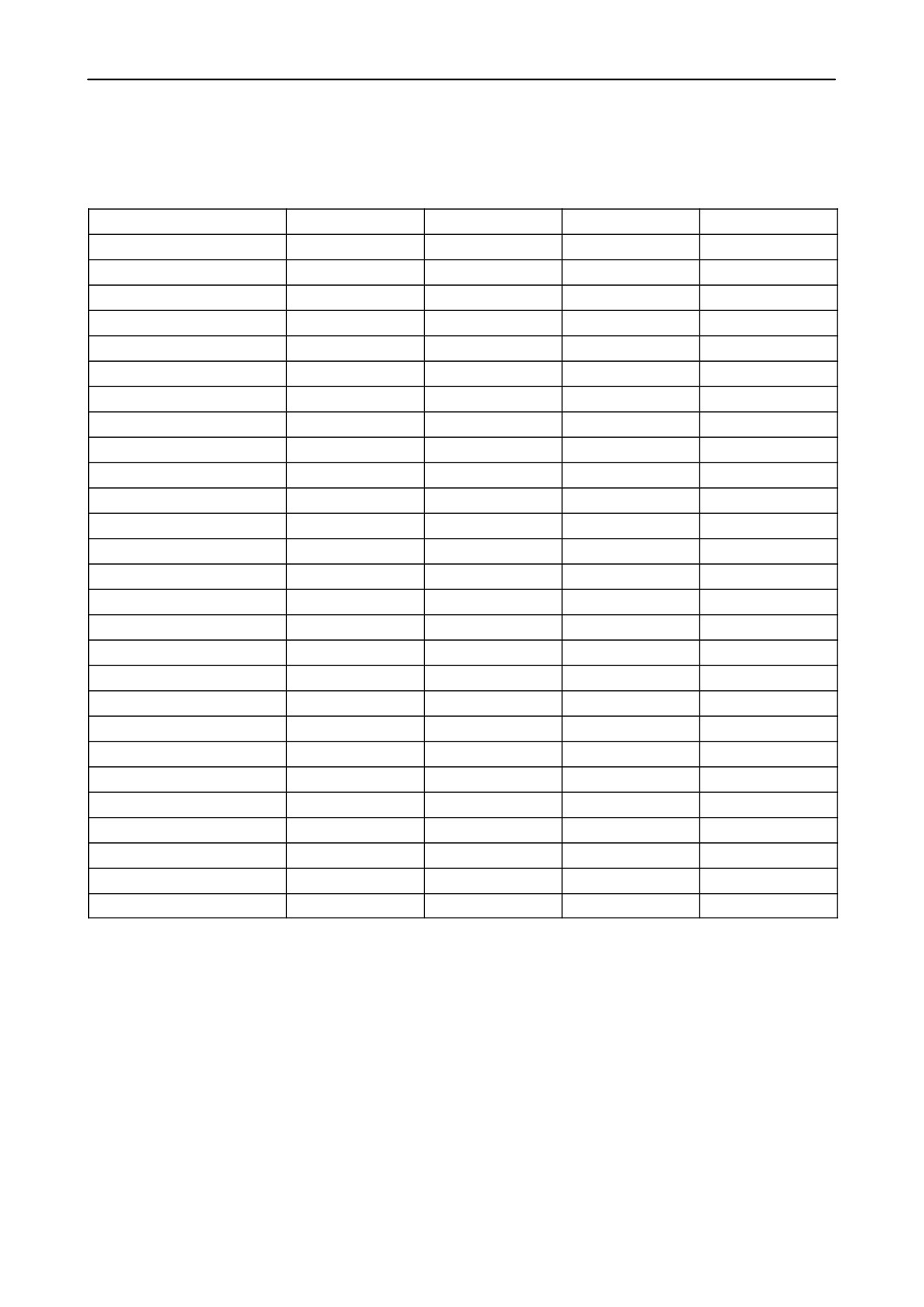
11. Header
In this sub-menu the operator can find the following
items depend the attachment in these sequence:
Maize header
Grain header
Pick-up header
Draper/Varifeedt
Header type
x
x
x
x
Header platform type
x
x
x
x
Header usage
x
x
x
Header width
x
x
x
Rows in use
x
Total rows
x
Row distance
x
Header raise rate
x
x
x
x
Header lower rate
x
x
x
x
Header threshold pressure
x
x
x
x
Minimum reel speed
x
x
x
Auto reel speed slope
x
x
x
Header lateral float
x
x
x
x
Header Autofloatt
x
x
x
x
Reel drive type
x
x
x
Maximum stubble height
x
x
x
x
Header lift cylinders
x
x
x
x
Auto header lift
x
x
x
x
Reel fore-back
x
x
x
Vertical knives
x
x
x
Reel vertical position
x
x
x
Reel horizontal position
x
x
x
Reel speed sensor
x
x
x
Hydraulic deck plates
x
x
Height sensitivity
x
x
x
x
Tilt sensitivity
x
x
x
x
Tilt/Knife position valve
x
x
x
2-142
SECTION 2 - CONTROLS, INSTRUMENTS AND OPERATION
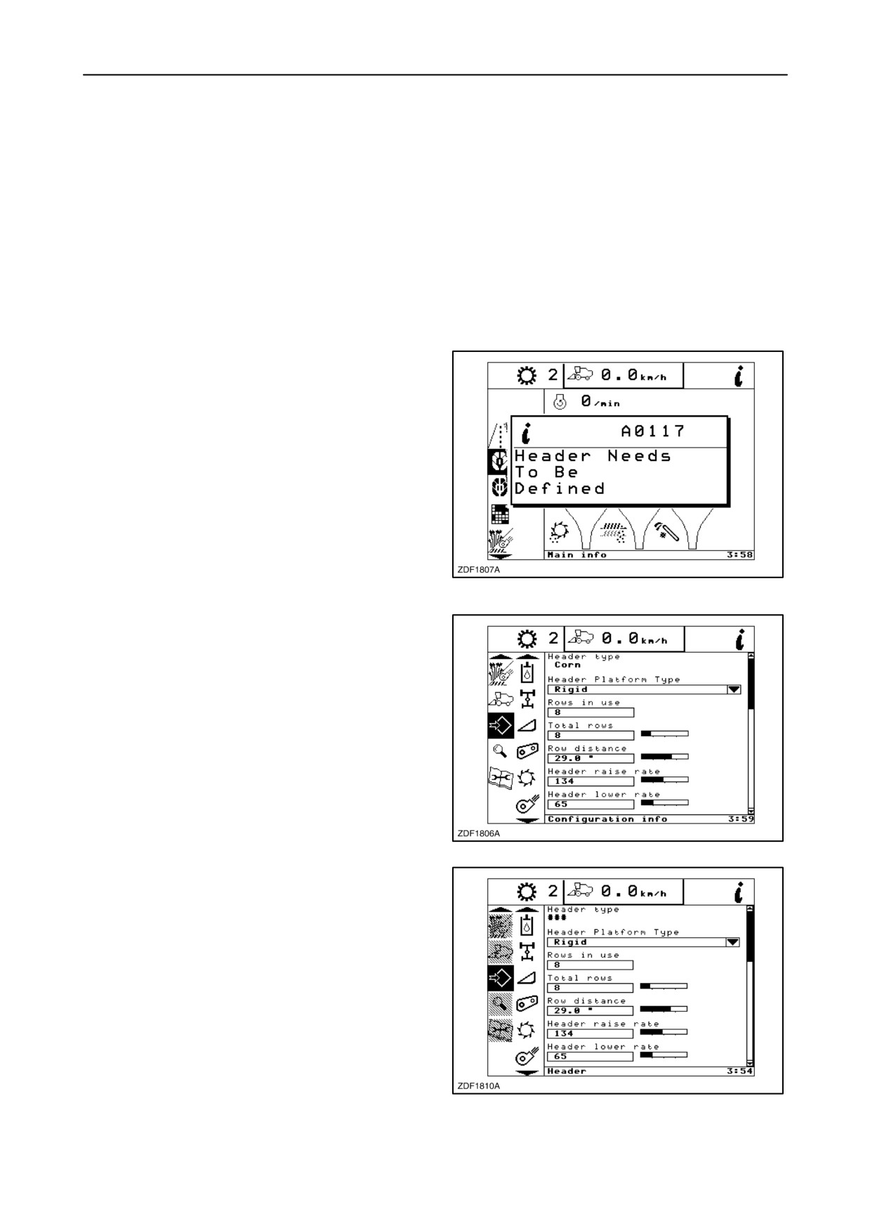
• Header type
If the header is equipped with a header recognition
sensor and is recognised by the combine, the system
will search through the four memorized header blocks
and all information for the corresponding block will be
shown in the header configuration menu and used for
proper header operation.
In case it is programmable or default header, than
there is a possibility to change the first line.
When the header with recognition sensor is fitted to
the combine and no matching header block is found,
the system will look to find a non defined block, if one
is found it will became the header block for the
attached header.
or
If all header blocks are already used, the system will
look for the least used block and redefine it for the
attached header.
In both cases a pop-up screen appears:
Message: “Header needs to be defined”.
254
If a header is recognised, the upper line cannot be
changed by the operator.
255
The operator can also configure an attached header
as “programmable”.
This feature can be used if the customer has two
headers of the same type and is frequently rotating
the use of both headers on the same combine.
When the header type sensor is installed as
“programmable”, the header type configuration will
be marked as shown.
This symbol ”###” communicates the operator that
the connected header is not defined.
256
2-143
SECTION 2 - CONTROLS, INSTRUMENTS AND OPERATION
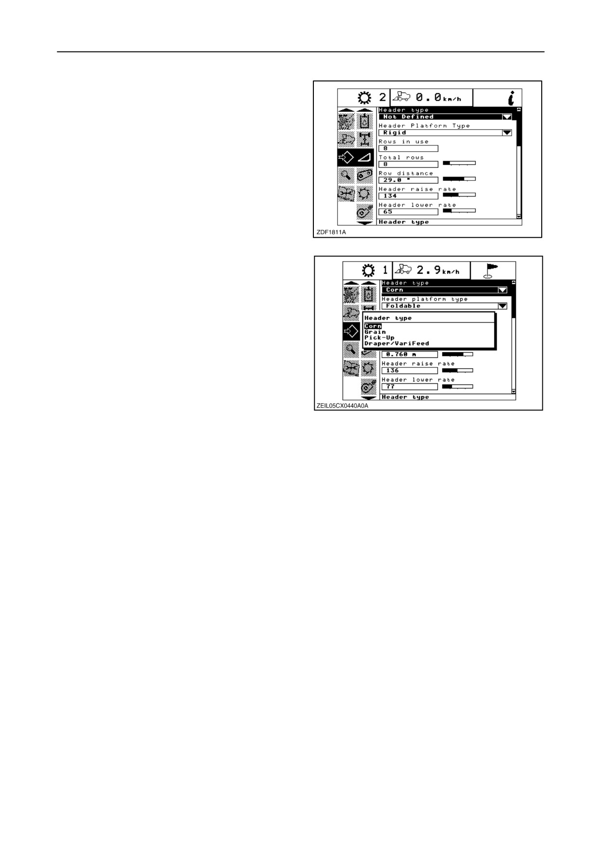
When the operator highlights the header type
configuration the symbol “xxx” will change to “Not
Defined” and the configuration will become editable.
257
If press “enter”, a pop-up screen appears showing the
different headers.
• Corn
• Grain
• Pick-up
• Draper / Varifeed
Select the header type attached to the combine and
press “enter”.
258
2-144
SECTION 2 - CONTROLS, INSTRUMENTS AND OPERATION
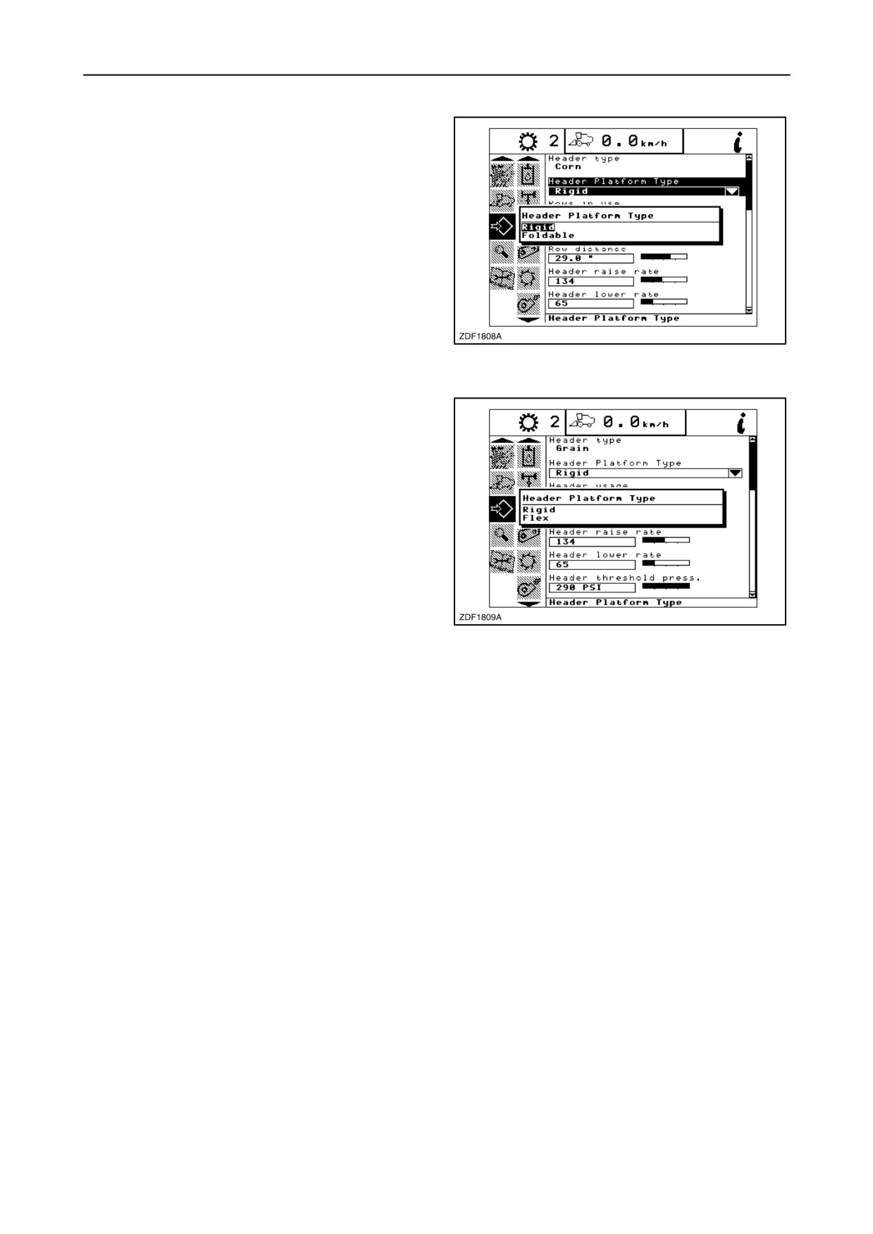
• Header platform type
To select the header configuration, proceed as
follows:
1. Select the item ”Header platform type” in the
header sub-menu and press “enter”.
2. A pop-up screen appears on the screen showing
the different header types depending on the
selected “Header type”.
3. Select the correct header type using the ”up” or
”down” navigation keys.
259
4. Press ”enter” to store.
• Grain header, Draper
Rigid
Flex
• Corn header
Rigid
Foldable
• Pick-up
No selection to be made.
260
2-145
SECTION 2 - CONTROLS, INSTRUMENTS AND OPERATION
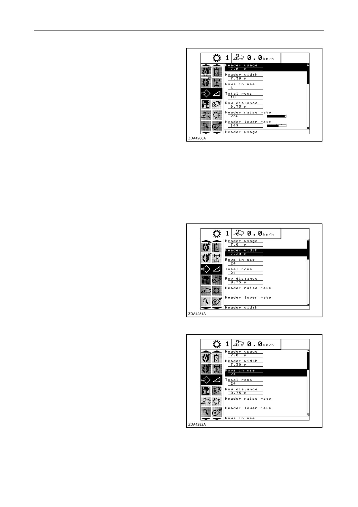
• Header usage
If the full header width is not used during harvesting,
a header width correction has to be made to obtain a
correct area counting.
Proceed as follows:
1. Select the item ”Header Usage” in the header
sub-menu.
2. Change the ”usage”, using the ”+” and/or ”-”
keys.
261
3. Press ”Enter” to store the new value.
NOTE: The value can only be changed in steps of
1m (Metric) or 1 ft (Imperial).
Remark: It is possible to make the header usage
value visible on the main work screen as you will use
this screen most of the time while harvesting.
• Header width
When another header is attached to the combine, it
is necessary to recalibrate the header width to obtain
a correct area counting.
Proceed as follows:
1. Select the item ”Header width”.
2. Use the ”+” or ”-” buttons to change the header
width.
3. Press ”enter” to store.
NOTE: The value can only be changed in steps of
0.1m.
262
• Rows in use
In case a corn header is attached to the combine and
to obtain a correct hectare counting, the number of
rows that are used can be adjusted.
Proceed as follows:
1. Select the item ”Rows in use”.
2. Change the value, using the ”+” and/or ”-” keys.
NOTE: The value can be changed from 24 down to
0.
3. Press ”Enter” to store the new value.
263
Remark: It is possible to make the ”Rows in use”
value visible on the main work screen as you will use
this screen most of the time while harvesting.
2-146
SECTION 2 - CONTROLS, INSTRUMENTS AND OPERATION
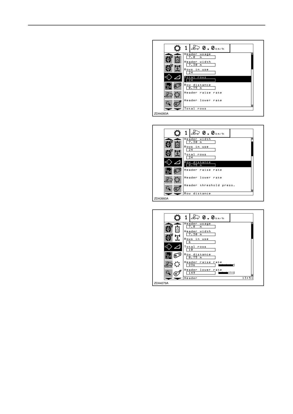
• Total rows
When another corn header is attached to the
combine, it is necessary to recalibrate the total
number of rows to obtain a correct area counting.
Proceed as follows:
1. Select the item ”Total rows”.
2. Use the ”+” or ”-” buttons to change the setting.
3. Press ”enter” to store.
NOTE: The setting can be changed from 4 up to 24.
264
• Row distance
When another corn header is attached to the
combine, it is necessary to recalibrate the row
distance to obtain a correct area counting.
Proceed as follows:
1. Select the item ”Row distance”.
2. Use the ”+” or ”-” buttons to change the setting.
3. Press ”enter” to store.
265
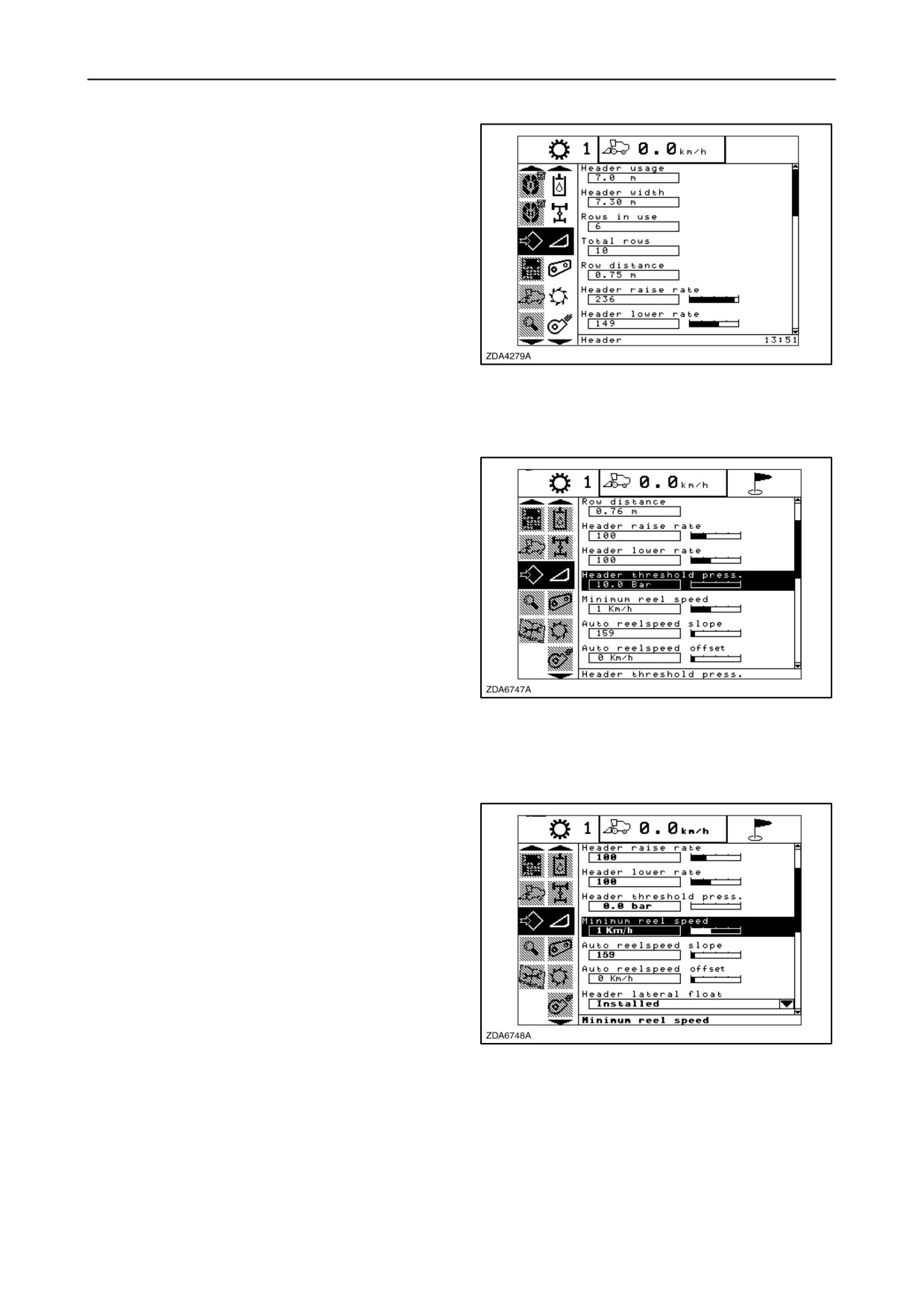
• Header raise rate
The manual slow raise speed (first speed on the
header height rocker switch of the multifunction
handle) can be changed.
Proceed as follows:
1. Select the item ”Header raise rate”.
2. Use the ”+” or ”-” buttons to change the setting.
3. Press ”enter” to store.
NOTE: The setting can be changed between 32 and
250% in steps of 34.
266
Factory set=100%.
2-147
SECTION 2 - CONTROLS, INSTRUMENTS AND OPERATION
• Header lower rate
The fast lower speed (the automatic header height
control button or second speed on the header height
rocker switch of the multi-function handle) can be
changed.
Proceed as follows:
1. Select the item ”Header lower rate”.
2. Use the ”+” or ”-” buttons to change the setting.
3. Press ”enter” to store.
NOTE: The setting can be changed between 2 and
250% in steps of 7.
267
Factory-set = 100%.
• Header threshold pressure
This setting determines when the header height
control system should switch between
”stubble
height” or “Autofloatt” mode and ”compensation”
mode.
Proceed as follows:
1. Select the item ”Header threshold Press.”.
2. Use the ”+” or ”-” buttons to change the setting.
3. Press ”enter” to store.
NOTE: Value can be changed between 2 bar and 20
bar (29 - 290 psi) in steps of 1 bar.
268
Factory-set = 10 bar (147 psi).
• Minimum reel speed
A minimum reel speed can be set when working with
the automatic reel to ground speed synchronization.
Proceed as follows:
1. Select the item ”Minimum reel speed”.
2. Use the ”+” or ”-” buttons to change the setting.
3. Press ”enter” to store.
NOTE: Value can be changed between 0 and 10 km/h
in steps of 0,1 km/h.
269
Factory-set = 1 km/h
2-148
SECTION 2 - CONTROLS, INSTRUMENTS AND OPERATION
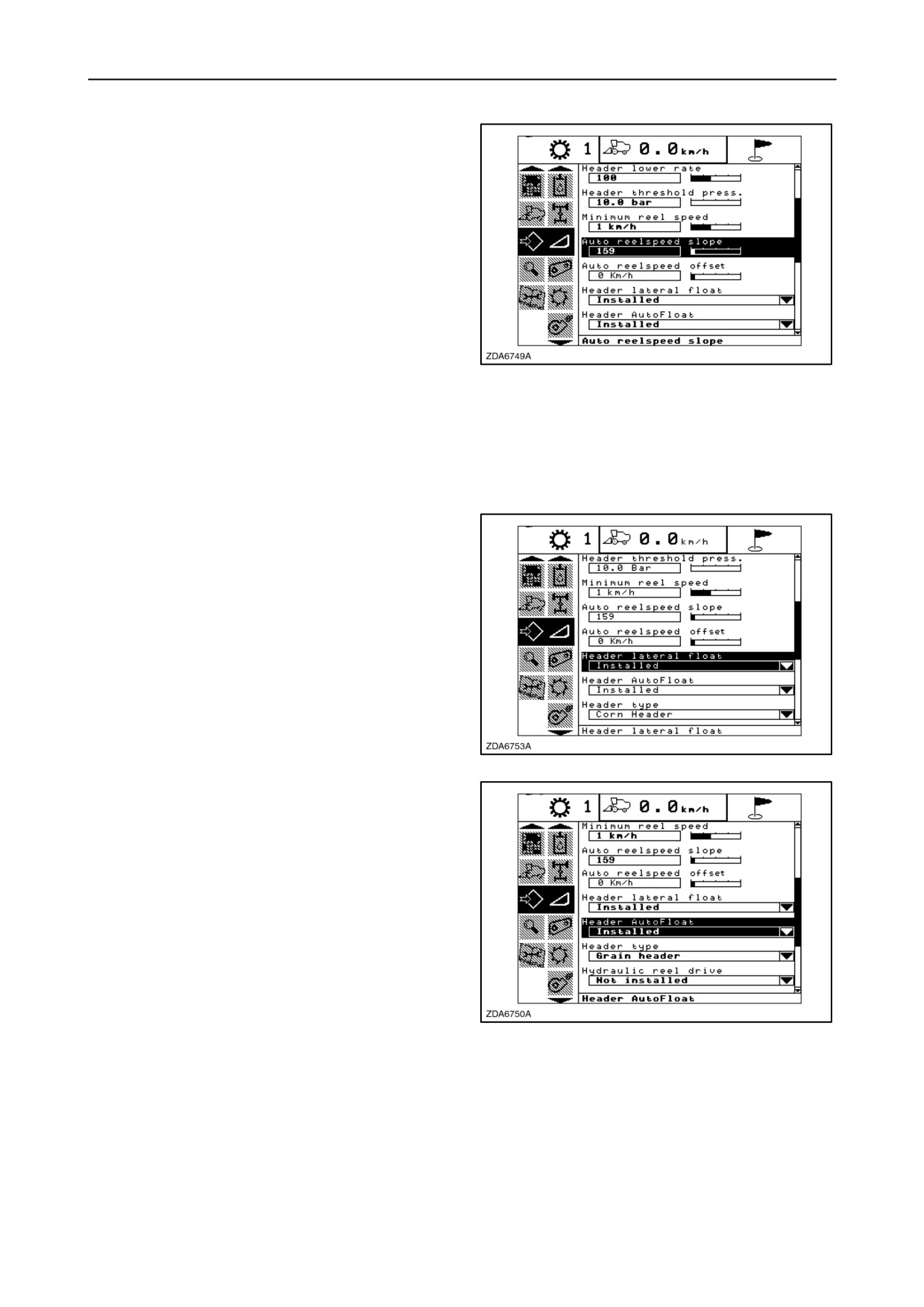
• Auto reel speed slope
The reel speed slope is the relationship between the
ground speed and the reel speed depending on the
header type and is configurable by the operator.
Factory-set values for optimum performance.
See below:
• Standard hydraulic reel drive: 133
• Mechanical reel drive: 159
• Pick-up reel drive: 167
270
• Extra-capacity hydraulic reel: 196
When increasing this value, reel runs faster than the
forward speed.
• Header lateral float
If press “enter” when this item is selected, a pop-up
screen appears, showing the two possibilities
“Installed” or “Not installed”.
Using the ”up” or “down” navigation keys to select and
press “enter” to confirm your choice.
271
• Header Autofloatt
If press “enter” when this item is selected, a pop-up
screen appears, showing the two possibilities
“Installed” or “Not installed”.
Using the ”up” or “down” navigation keys to select and
press “enter” to confirm your choice.
272
2-149
SECTION 2 - CONTROLS, INSTRUMENTS AND OPERATION
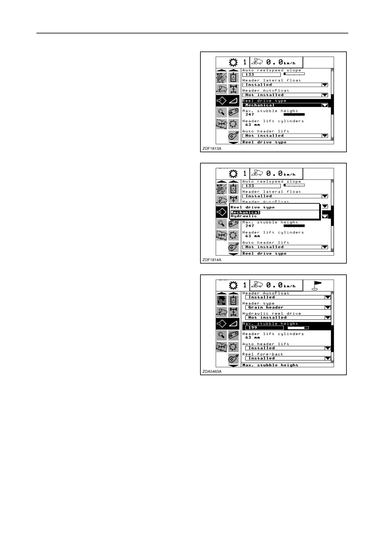
• Reel drive type
If press “enter” when this item is selected, a pop-up
screen appears, showing the two possibilities
“Mechanical” or “Hydraulic”.
Using the ”up” or “down” navigation keys to select and
press “enter” to confirm your choice.
273
274
• Maximum stubble height
This is necessary to know from which height the area
counter should stop or start counting. When the
header is raised above this level the combine
assumes you are not cutting any crop. So you have
to put the header at a certain height you will always
exceed when not cutting crop and always stay below
when cutting crop.
NOTE: This value can only be changed by
calibration. Refer to “CALIBRATIONS FOR BASIC
OPERATION”, paragraph headed “Calibration of the
Maximum stubble height” in this section.
275
• Header lift cylinders
This item is factory-set and can not be changed.
2-150
SECTION 2 - CONTROLS, INSTRUMENTS AND OPERATION
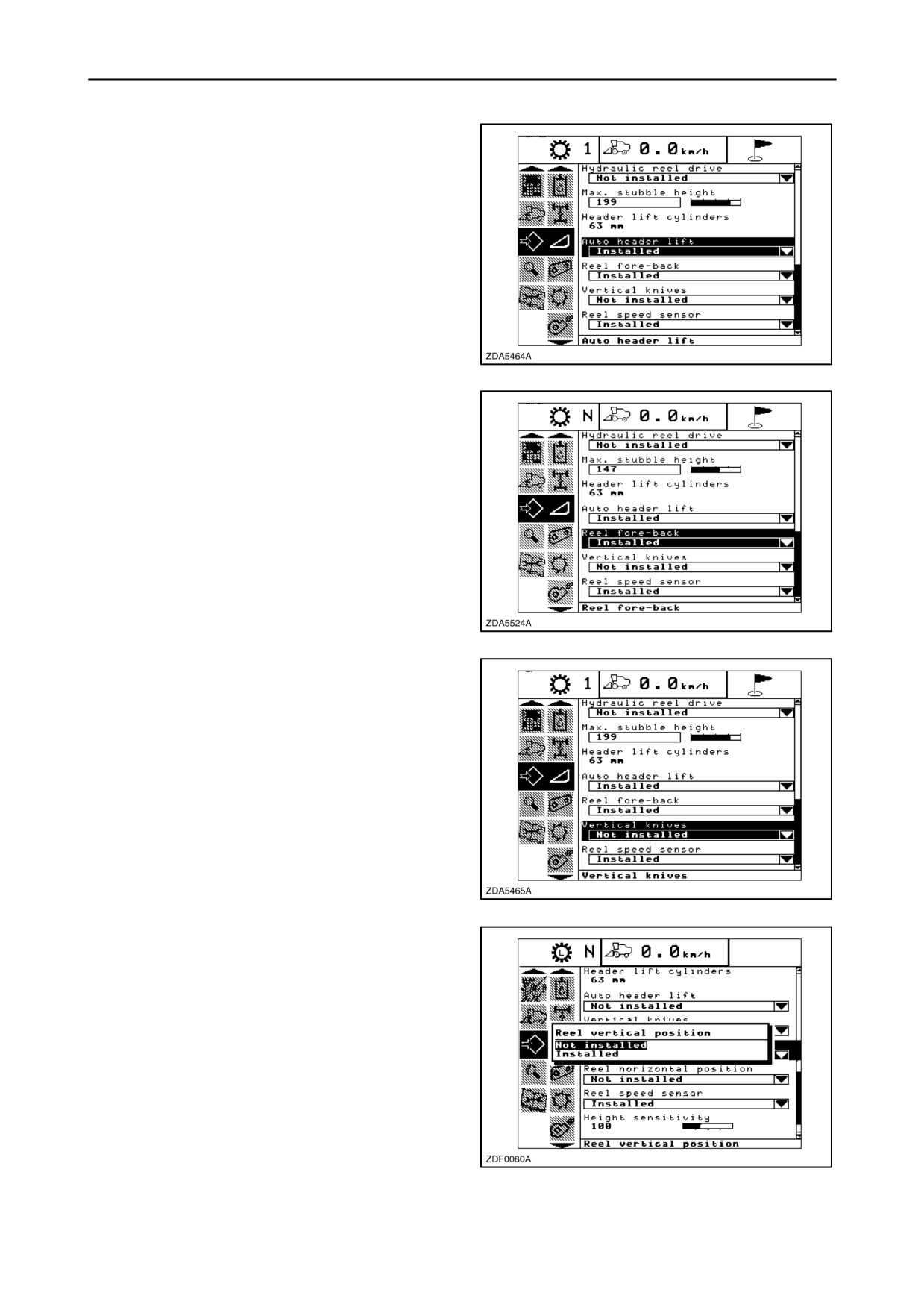
• Auto header lift
This automatic system is built in to protect the header
skid shoes in case of reversing the combine.
If press “enter” when this item is selected, a pop-up
screen appears, showing the two possibilities
“Installed” or “Not installed”.
Using the ”up” or “down” navigation keys to select and
press “enter” to confirm your choice.
276
• Reel fore-back
If press “enter” when this item is selected, a pop-up
screen appears, showing the two possibilities
“Installed” or “Not installed”.
Using the ”up” or “down” navigation keys to select and
press “enter” to confirm your choice.
277
• Vertical knives
If press “enter” when this item is selected, a pop-up
screen appears, showing the two possibilities
“Installed” or “Not installed”.
Using the ”up” or “down” navigation keys to select and
press “enter” to confirm your choice.
278
• Reel vertical position
If press “enter” when this item is selected, a pop-up
screen appears, showing the two possibilities
“Installed” or “Not installed”.
Using the ”up” or “down” navigation keys to select and
press “enter” to confirm your choice.
279
2-151
SECTION 2 - CONTROLS, INSTRUMENTS AND OPERATION
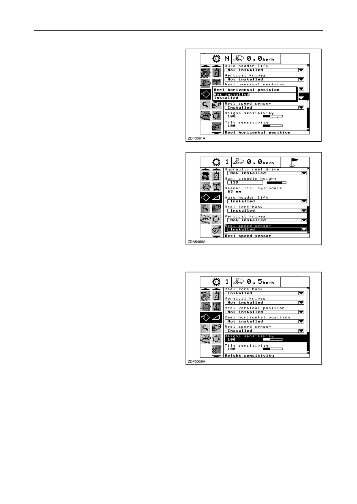
• Reel horizontal position
If press “enter” when this item is selected, a pop-up
screen appears, showing the two possibilities
“Installed” or “Not installed”.
Using the ”up” or “down” navigation keys to select and
press “enter” to confirm your choice.
280
• Reel speed sensor
A proper sensor should be installed on the header.
If working with reel to ground speed synchronization
is it necessary to select “installed” for this item.
(if mechanical reel drive)
If press “enter” when this item is selected, a pop-up
screen appears, showing the two possibilities
“Installed” or “Not installed”.
Using the ”up” or “down” navigation keys to select and
press “enter” to confirm your choice.
281
• Height sensitivity (in Autofloatt
)
To change the up and down sensitivity of the straw
elevator, proceed as follows:
1. Engage threshing and straw elevator.
2. Select the item “Height sensitivity”.
3. Use the “+” or “-” buttons to change the setting.
4. Press “enter” to store.
NOTE: Value can be changed between 0 and 250 in
282
steps of 10
Factory-set= 100
2-152
SECTION 2 - CONTROLS, INSTRUMENTS AND OPERATION
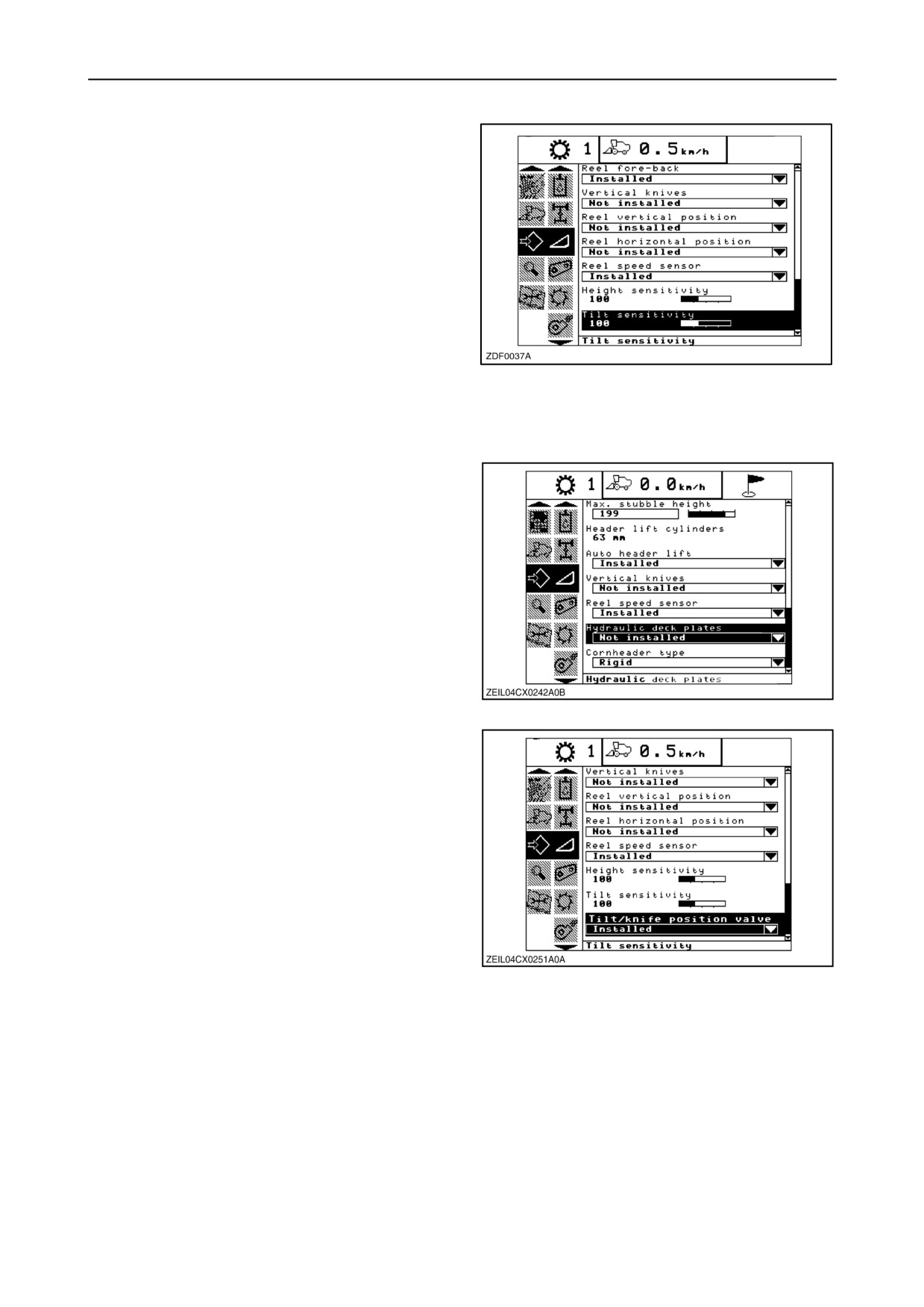
• Tilt sensitivity (in Autofloatt
)
To change the lateral flotation sensitivity, proceed as
follows:
1. Engage threshing and straw elevator.
2. Select the item “Tilt sensitivity”.
3. Use the “+” or “-” buttons to change the setting.
4. Press “enter” to store.
NOTE: Value can be changed between 0 and 250 in
283
steps of 10
Factory-set= 100
• Hydraulic deck plates
If press “enter” when this item is selected, a pop-up
screen appears, showing the two possibilities
“Installed” or “Not installed”.
(Not installed= electrical deck plates)
Using the ”up” or “down” navigation keys to select and
press “enter” to confirm your choice.
284
• Tilt/Knife position valve
If press “enter” when this item is selected, a pop-up
screen appears, showing the two possibilities
“Installed” or “Not installed”.
Using the ”up” or “down” navigation keys to select and
press “enter” to confirm your choice.
285
2-153
SECTION 2 - CONTROLS, INSTRUMENTS AND OPERATION
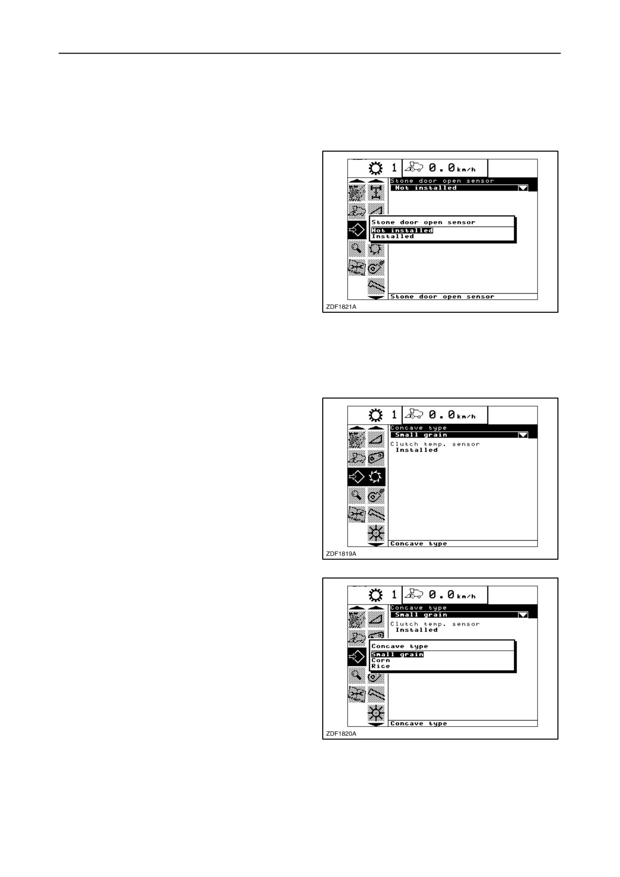
12. Straw elevator
In this sub-menu the operator can set following item:
• Stone door open sensor (not used)
Press “enter” when the desired item is selected, a
pop-up screen appears, showing the two possibilities
“Installed” or “Not installed”.
NOTE: This should be set to “Not installed” to avoid
false warnings.
286
13. Threshing
In this sub-menu the operator can set following item:
• Concave type
In case the combine is being rebuild from crop to be
harvested, the correct concave type should be
selected.
Proceed as follows:
1. Select the item ”Concave type”.
2. Press ”enter”.
287
3. Pop-up screen 1 appears showing the different
selections.
4. Select the correct concave type using the ”up” or
”down” navigation keys.
5. Press ”enter” to store.
NOTE: The other item in the threshing sub menu is
factory-set and should not be changed.
288
2-154
SECTION 2 - CONTROLS, INSTRUMENTS AND OPERATION
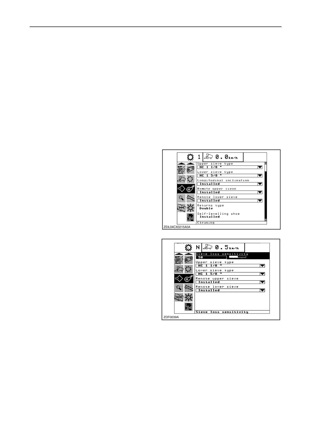
14. Cleaning
In this sub-menu the operator can set following items:
• Sieve loss sensitivity
• Upper sieve type
• Lower sieve type
• Longitudinal inclination
• Remote upper sieve
• Remote lower sieve
NOTE: The other items in the cleaning sub menu are
factory-set and should not be changed.
289
• Sieve loss sensitivity
To change, proceed as follows:
1. Enter to the information box and select “Sieve
loss sensitivity”.
2. To change the value using the “+” and ”-” keys
and press “enter” to store.
290
2-155
SECTION 2 - CONTROLS, INSTRUMENTS AND OPERATION
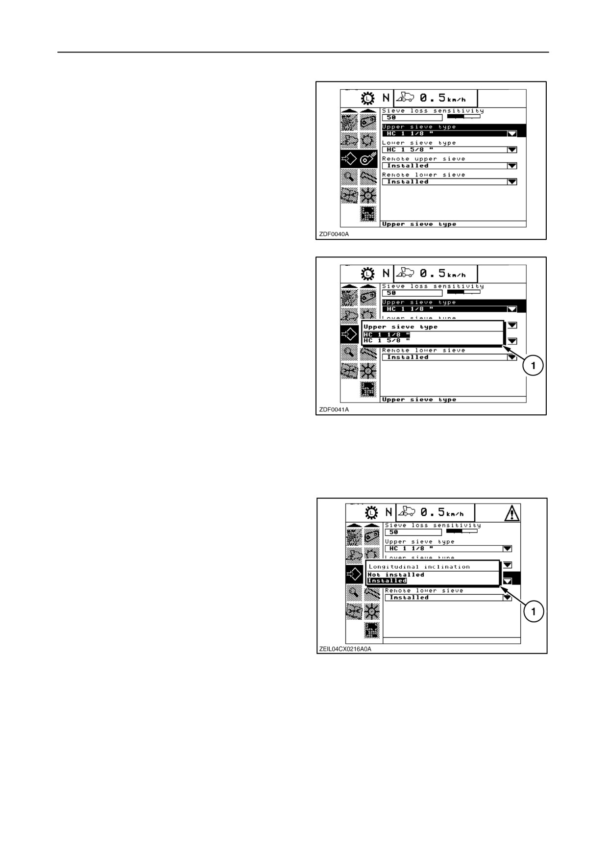
• Upper sieve type
1. Enter to the information box and select
“Upper sieve type”.
2. Press ”enter”.
291
3. Pop-up screen 1 appears showing the different
selections.
4. Select the correct upper sieve type using the ”up”
or ”down” navigation keys.
5. Press ”enter” to store.
292
• Lower sieve type
Same procedure as “Upper sieve type”.
• Longitudinal inclination
(SmartSteert system)
If press “enter” when this item is selected, a pop-up
screen 1 appears, showing the two possibilities
“Installed” or “Not installed”.
Using the ”up” or “down” navigation keys to select and
press “enter” to confirm your choice.
293
2-156
SECTION 2 - CONTROLS, INSTRUMENTS AND OPERATION
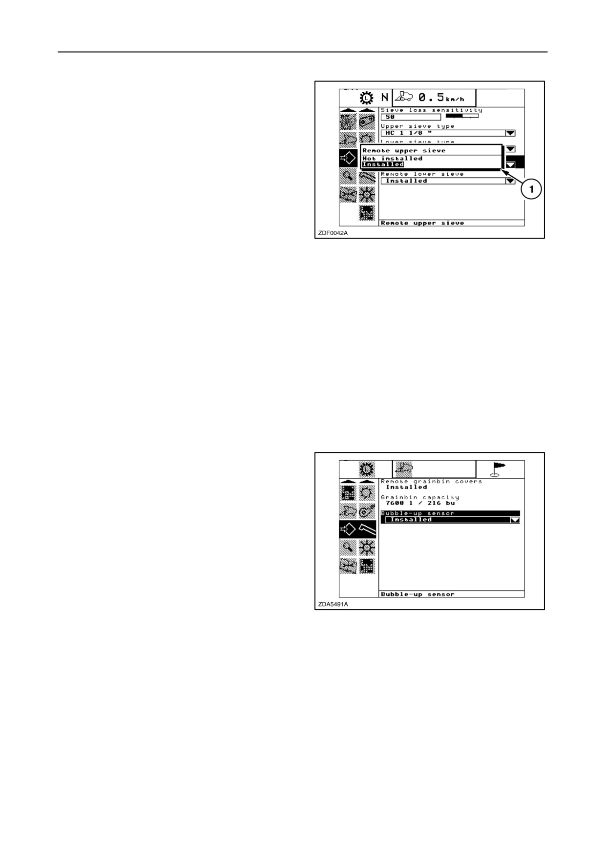
• Remote upper sieve
If press “enter” when this item is selected, a pop-up
screen 1 appears, showing the two possibilities
“Installed” or “Not installed”.
Using the ”up” or “down” navigation keys to select and
press “enter” to confirm your choice.
294
• Remote lower sieve
Same procedure as “Remote upper sieve”.
15. Clean grain/Unloading
In this sub-menu the operator can set following item:
• Bubble-up sensor
If press “enter” when this item is selected, a pop-up
screen appears, showing the two possibilities
“Installed” or “Not installed”.
Using the ”up” or “down” navigation keys to select and
press “enter” to confirm your choice.
NOTE: The other items in the clean grain / Unloading
sub-menu are factory-set and can not be changed.
295
2-157
SECTION 2 - CONTROLS, INSTRUMENTS AND OPERATION
16. Residue
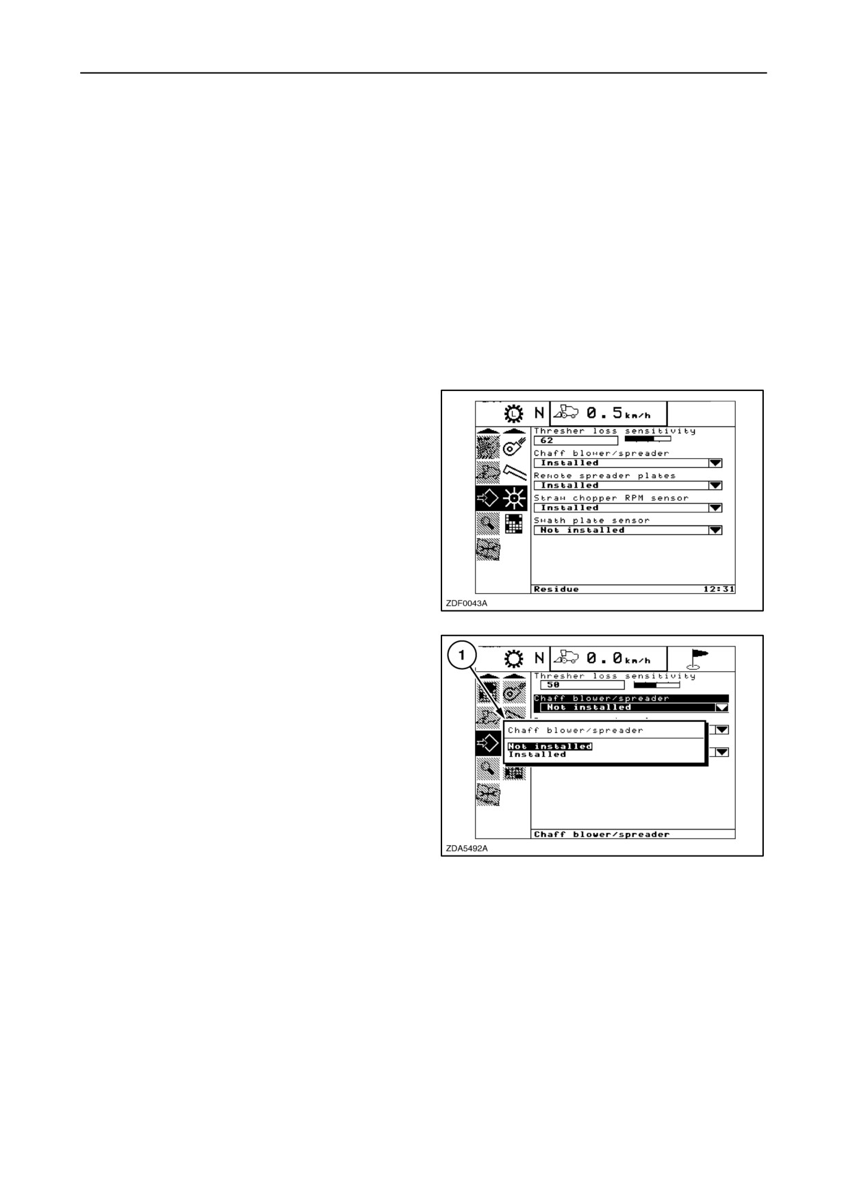
In this sub-menu the operator can set following items:
• Thresher loss sensitivity
• Chaff blower/spreader
• Remote spreader plates
• Straw chopper rpm sensor
• Swath plate sensor
• Thresher loss sensitivity
To change, proceed as follows:
1. Enter to the information box and select
“Thresher loss sensitivity”.
2. To change the value using the “+” and”-” keys and
press “enter” to store.
296
• Chaff blower
If press “enter” when this item is selected, a pop-up
screen 1 appears, showing the two possibilities
“Installed” or “Not installed”.
Using the ”up” or “down” navigation keys to select and
press “enter” to confirm your choice.
297
• Remote spreader plates
To change, same procedure as “Chaff blower”.
• Straw chopper rpm sensor
To change, same procedure as “Chaff blower”.
• Swath plate sensor
To change, same procedure as “Chaff blower”.
2-158
SECTION 2 - CONTROLS, INSTRUMENTS AND OPERATION
17. Precision farming
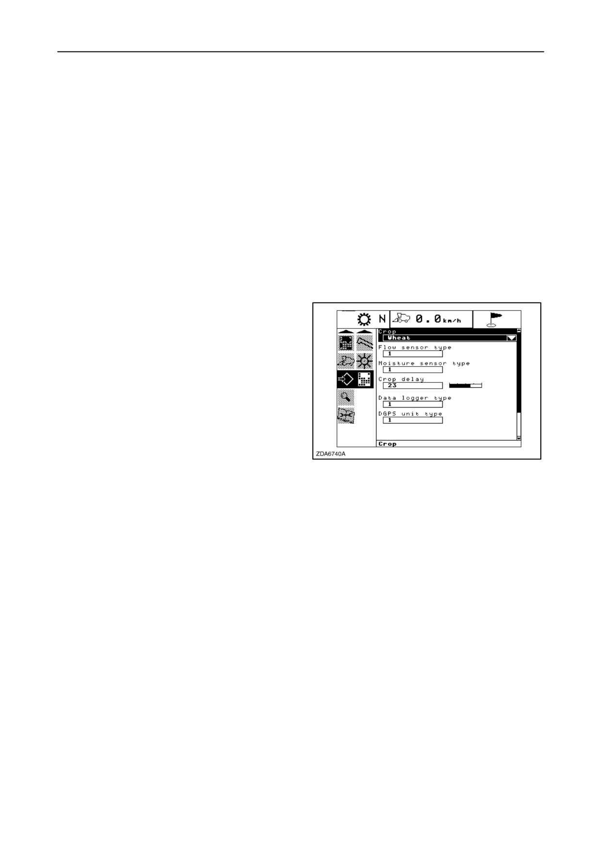
In this sub-menu the operator can set following items:
• Crop
• Flow sensor type
• Moisture sensor type
• Crop delay
• Data logger type
• DGPS unit type
• Crop
To change “crop”, proceed as follows:
1. Enter to the information box and select “Crop”.
2. Press “Enter”.
3. A pop-up screen appears with the current
selection highlighted.
4. Change the selection, using
“up” or
“down”
navigation keys and press “enter” to store.
298
5. The selected crop will be viewed.
NOTE: When using jobs in the Harvest Info screens
to logdata, DO NOT change the crop in this screen.
Only change crops while/during creating new jobs in
this case.
2-159
SECTION 2 - CONTROLS, INSTRUMENTS AND OPERATION
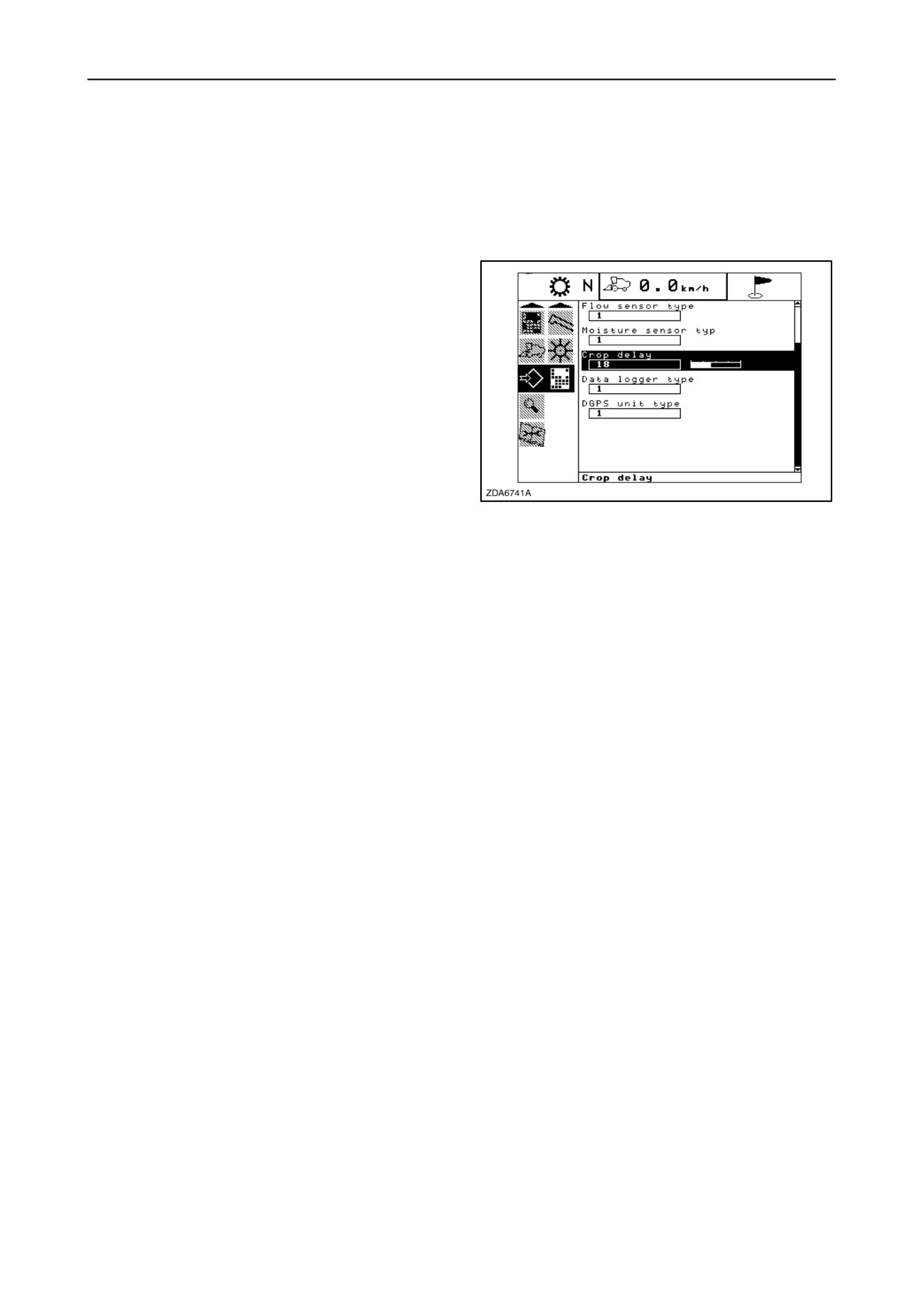
• Crop delay
This is the time (seconds) needed to transport the
crop from the header (cutting knife) to the grain flow
sensor on top of the grain elevator.
To change “Crop delay”, proceed as follows:
1. Enter to the information box and select “Crop
delay”.
2. To change the value using the “+” and”-” keys and
press “enter” to store.
Factory-set= 15
299
• Flow sensor type
• Moisture sensor type
• Data logger type
• DGPS unit type
The operator can make a choice between number “0”
and ”1”.
“0” = Not installed
“1” = Installed
To change the number using the
“+” and
“-”
navigation keys and press “enter” to store.
2-160
SECTION 2 - CONTROLS, INSTRUMENTS AND OPERATION
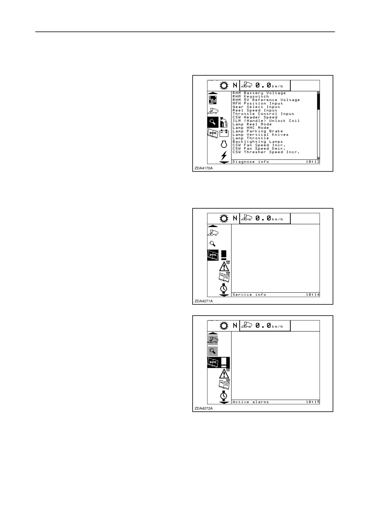
VIII DIAGNOSE INFO SCREEN
In the unlikely event a fault entered the
electric/electronic system, trouble-shooting routines
are incorporated to help to trace problems in the
electric or electronic system.
Several check routines can be selected which the
electronics will carry out.
300
IX SERVICE INFO SCREEN
Switch to the service menu as follows:
1. Select the service menu in the menu bar by using
the up and down navigation keys.
2. A sub-menu will appear next to the menu bar.
301
3. To enter that sub-menu, press the
”right”
navigation key.
4. Run through the sub-menu by using the up and
down navigation keys:
The ”up” key to select a screen ups the ladder.
The ”down” key to select a screen downs the
ladder.
Keeping the ”up” and ”down” navigation key
depressed will shift the menu quickly up or down.
The selected symbol always remains in the middle of
302
the menu bar and blinks to show the selected
position. When the navigation keys are not used for
a while, the selected symbol will stop blinking and will
be inverted until the navigation keys are used again.
2-161
SECTION 2 - CONTROLS, INSTRUMENTS AND OPERATION
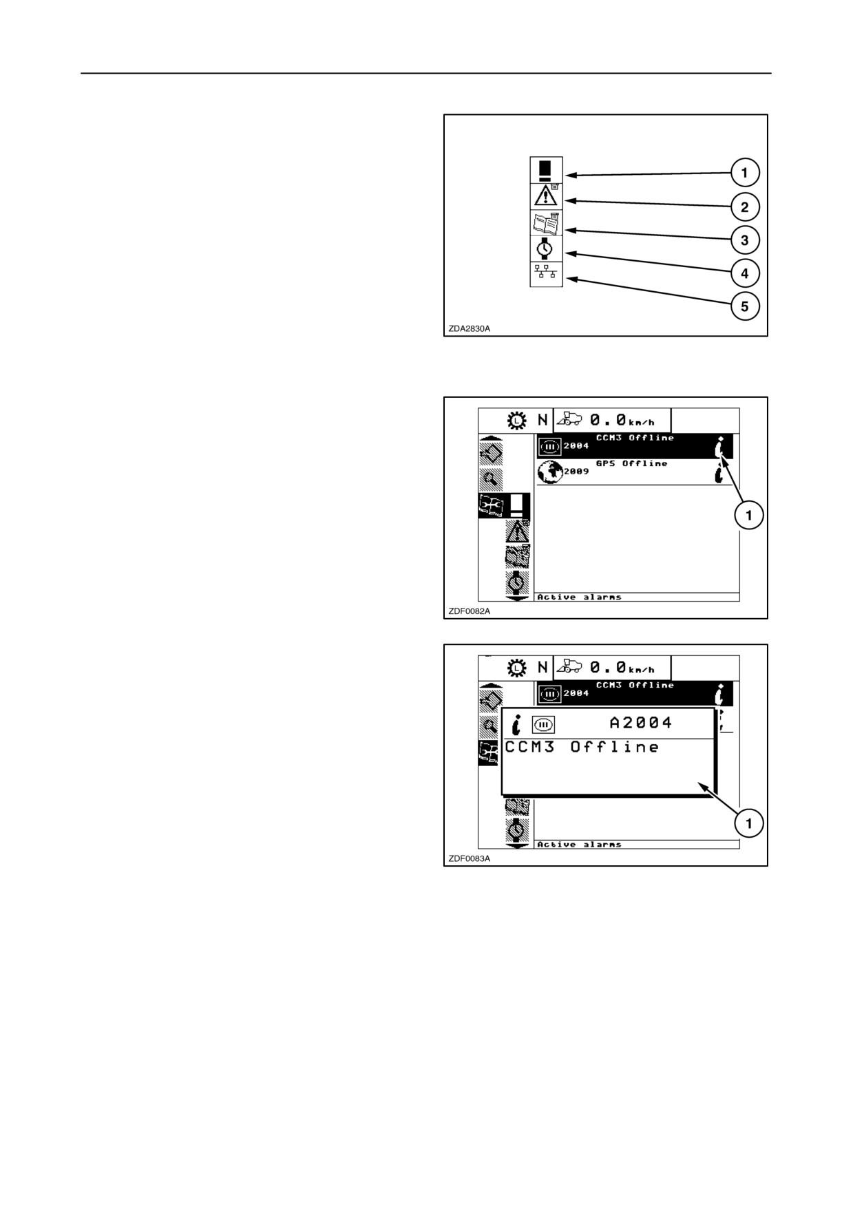
The different sub-menus in the service menu are
shown in figure 303 and will always appear in that
sequence.
1. Active alarms
2. Active errors
3. Error history
4. Service
5. Network
303
1. Active alarms
In this sub-menu you can find a list with the active
alarms.
NOTE: When there are active alarms (low, medium
or high), icon 1 appears at the right-hand side of the
alarm(s).
To view alarms in a separate pop-up screen, select
the alarm and press “enter”.
304
A pop-up screen 1 appears with more information of
the selected alarm.
305
2-162
SECTION 2 - CONTROLS, INSTRUMENTS AND OPERATION
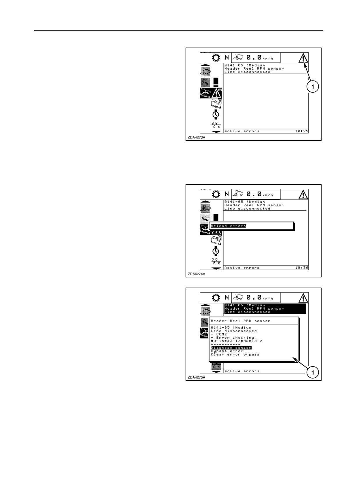
2. Active errors
In this sub-menu you can find a list with the active
errors.
NOTE: When there are active errors (low, medium or
high), icon 1 appears in the right upper corner of the
screen.
For each active error, the system provides the
following information:
• Error ID - fault code and priority
306
• Error description
• Fault code description
When pressing “enter” in these sub-menu a pop-up
screen appears: “Reload errors”.
Press “enter” to update this page.
307
To see some more information on a specific error,
enter the information box, select the specific error
and press enter.
Pop-up screen 1 will appear and provides following
information:
• Error description
• Error ID and fault code, Priority
• Fault code description
308
• Module
• Component + connector reference
2-163
SECTION 2 - CONTROLS, INSTRUMENTS AND OPERATION
3. Error history
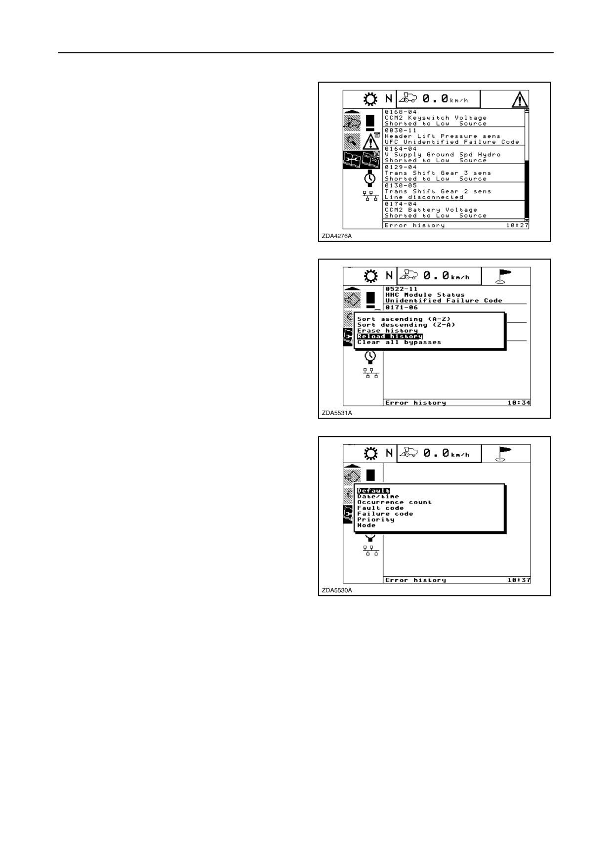
In this sub-menu you can find a list containing the
errors ever occurred on the combine since the error
(history) was last cleared.
309
If press “enter” in this sub menu, a pop-up screen
appears with the following items:
• Sort ascending (A-Z)
• Sort descending (Z-A)
• Erase history
• Clear all bypasses
Select in this list by using the
“up” and “down
navigation keys and press “enter”.
310
When select “Sort ascending (A-Z) or descending
(Z-A)”, a pop-up screen appears with the following
items:
• Default
• Date/time
• Occurrence count
• Fault code
• Failure code
311
• Priority
• Node
2-164
SECTION 2 - CONTROLS, INSTRUMENTS AND OPERATION
Select in this list by using the
“up” and “down
navigation keys and press “enter”.
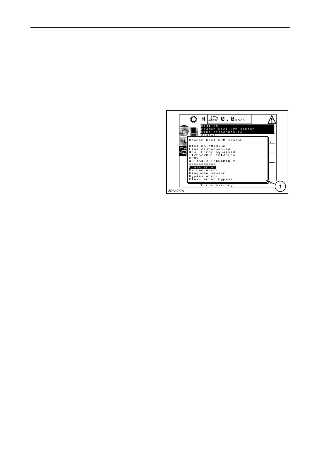
To see some more information on a specific error,
enter the information box, select the specific error
and press enter.
Pop-up screen 1 will appear and provides following
information:
• Error description
• Error ID - fault code # Priority
• Fault code description
• Frequency
• Date and time of last occurrence
• Module
• Component + connector reference
312
2-165
SECTION 2 - CONTROLS, INSTRUMENTS AND OPERATION
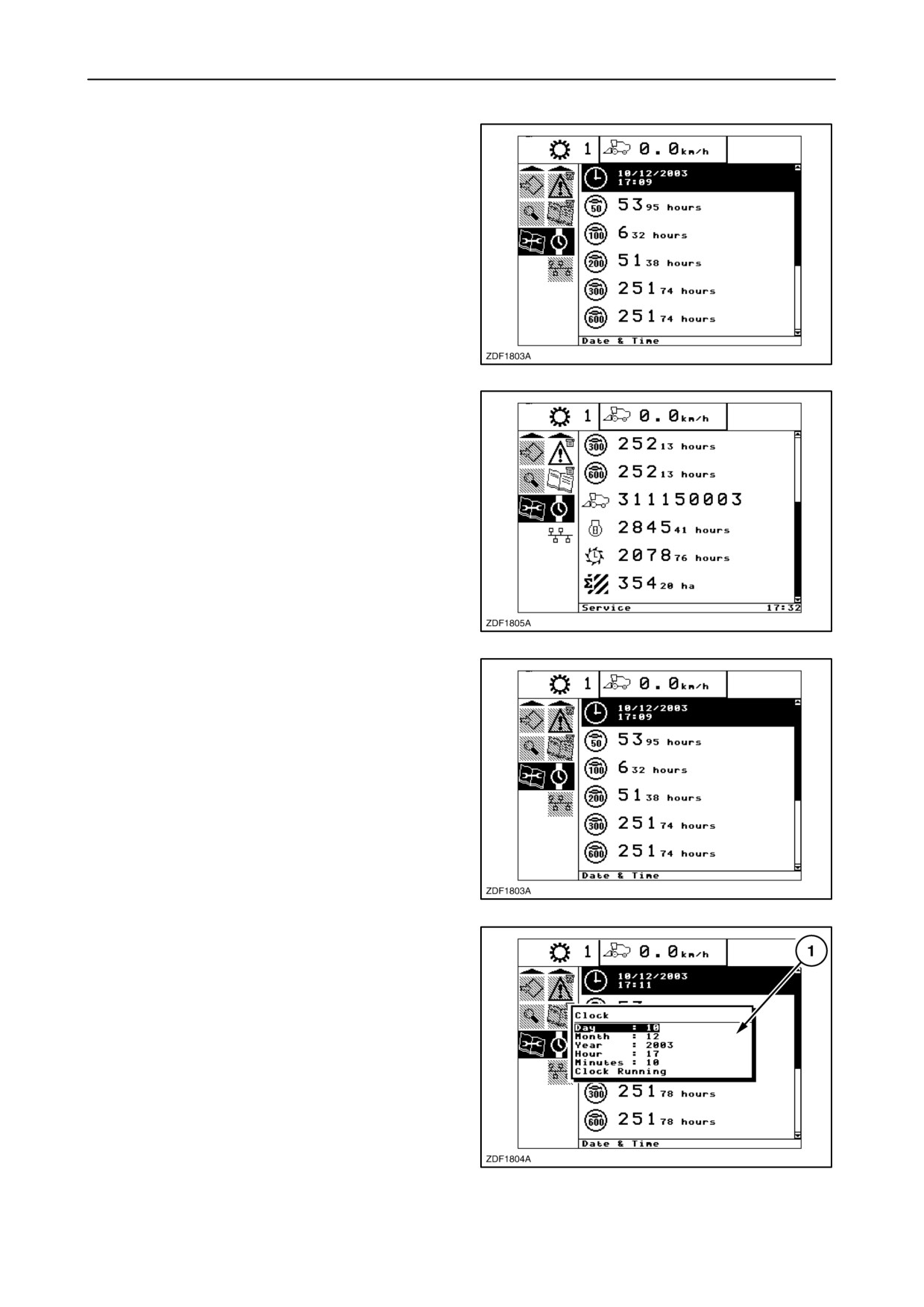
4. Service
In this sub-menu the following items are viewed:
• Date & Time
•
50 hours service interval
•
100 hours service interval
•
200 hours service interval
•
300 hours service interval
313
•
600 hours service interval
• Serial no.
• Total engine hours
• Total threshing hours
• Total hectares
314
• Date & Time
To change Date and Time settings, proceed as
follows:
1. Select the item ”Date & Time”.
2. Press ”enter”.
315
3. Pop-up screen 1 appears on the screen.
4. Use the ”up” and/or ”down” navigation keys to
select the item to change.
5. Use the ”+” and/or ”-” keys to change the setting.
6. Press ”enter” to confirm your choice. The next
item will become highlighted.
NOTE: If you change item ”Running” to “Idle”, then
the clock stops running.
NOTE: It is also possible to change the “Date & Time”
settings in the Road, Main or Custom info screen if
this item is selected for those screens.
316
2-166
SECTION 2 - CONTROLS, INSTRUMENTS AND OPERATION
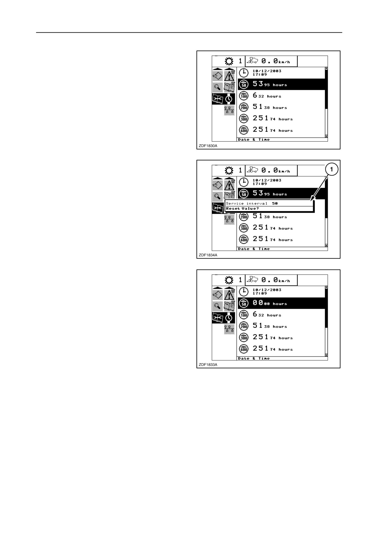
• XXX hours service interval
These hours are counted engine hours.
These values start blink if the service interval is
exceeded.
When set the ignition key in the contact position, and
one or more service intervals are exceeded, this page
is automatically shown.
317
After servicing the combine, the related service
interval has to be reset. Proceed as follows:
1. Enter to the information box and select
“XXX hours interval” (blinking) and press “enter”.
2. A pop-up screen (1) appears:
Message: ”Reset value“
318
3. To reset the value to zero, press “enter”.
319
2-167
SECTION 2 - CONTROLS, INSTRUMENTS AND OPERATION
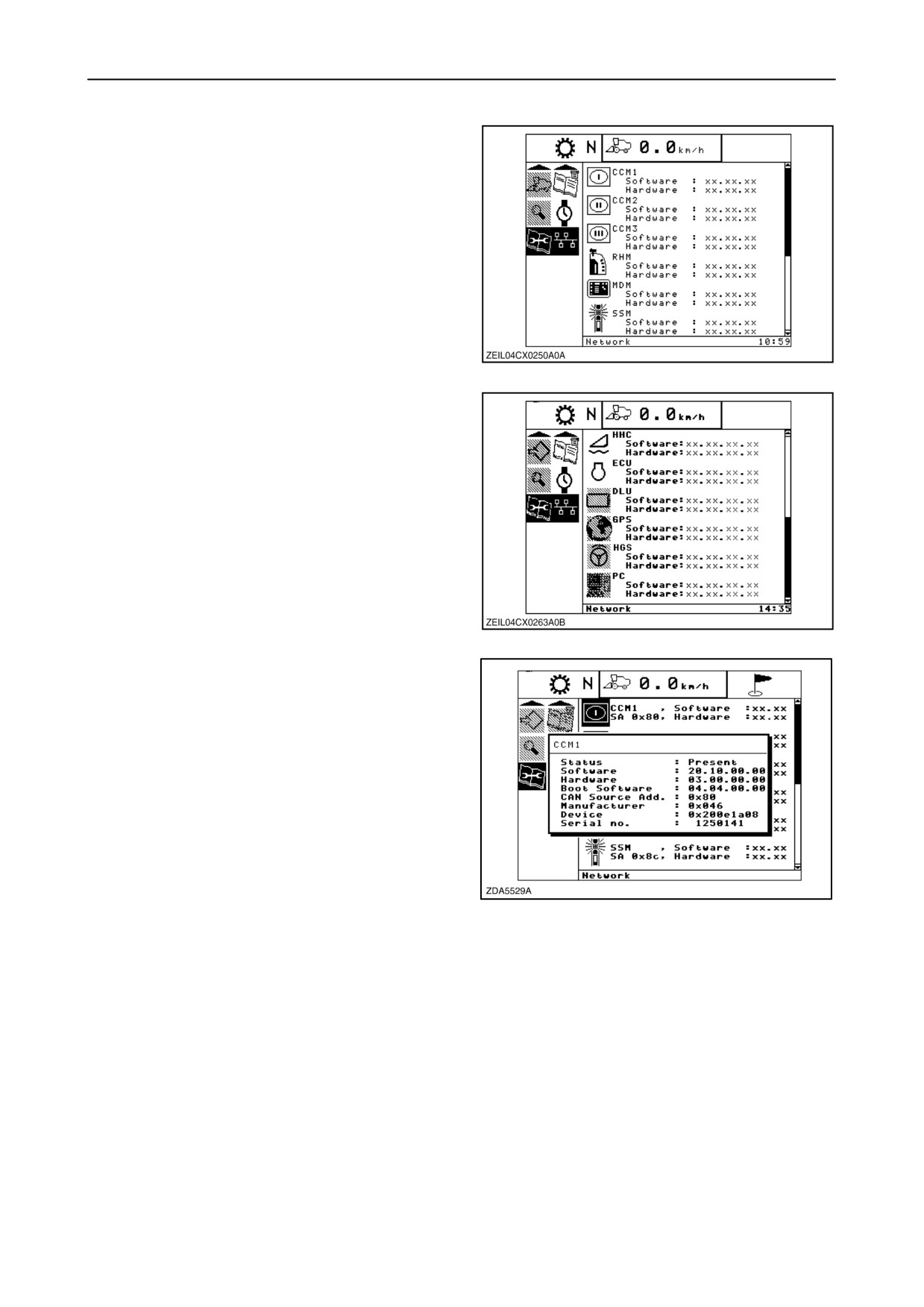
5. Network
In this sub-menu it is possible to check the software
version and the hardware version of the different
electronic components installed on the combine.
320
321
To see some more information on a specific electronic
component, enter the information box, select the
specific component and press enter.
A pop-up screen will appear and provides following
information:
• Status
• Software
• Hardware
322
• Boot software
• CAN Source Add.
• Manufacturer
• Device
• Serial no.
2-168
SECTION 2 - CONTROLS, INSTRUMENTS AND OPERATION
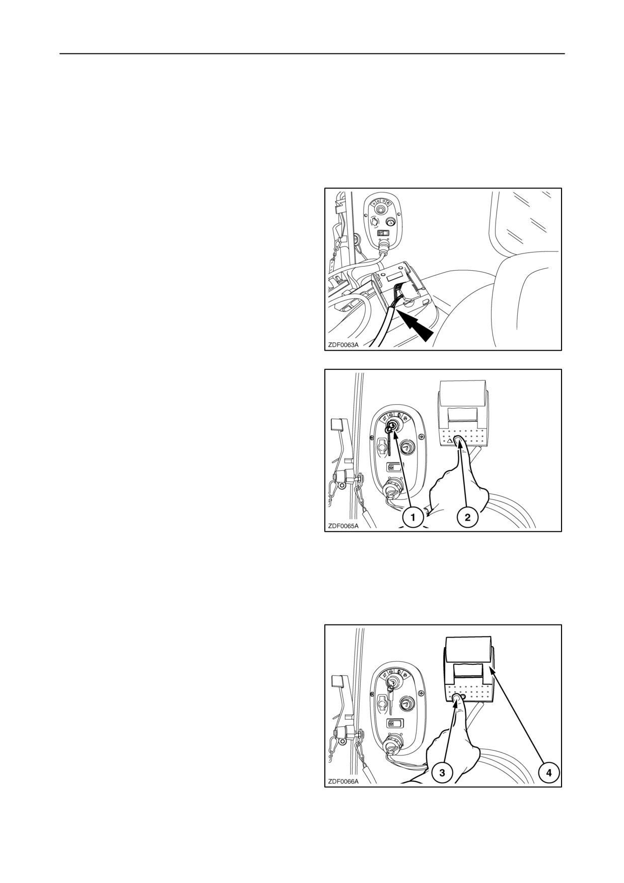
In cab printer (If installed)
With this printer is it possible to make a hard copy
print out of certain screens selected on the InfoViewt
monitor.
To use the printer, proceed as follows:
1. Connect the electric wires with the printer and the
diagnostics port as shown.
323
2. Hang up the printer near the start module as
shown (if foreseen).
3. Set the ignition key 1 in “contact” position.
4. Press button 2 to start-up the printer.
324
5. Using the navigation keys to select (sub-menu)
on the InfoViewt monitor the screen of which
you wish to have a hard copy print out.
6. Press the dot “.” button of the alphanumeric
keypad.
7. The printer starts printing now.
NOTE: Press the paper feed button 3 to scroll paper.
NOTE: To change paper, open the cover 4.
NOTE: Some screens can not be printed.
325
2-169